NOTE: These are actual working notes as well as project documentation. There is no shame in skipping to the acknowledgments and photos.
BACKGROUND:
USS Pampanito is a WW II submarine museum and memorial on Fisherman's Wharf in San Francisco. The boat is owned and operated by a non-profit and receives no government operating funds. Our goal is to make the submarine as complete and accurate to our summer 1945 restoration date as possible. This note is a description of the project to restore her 5" 25 cal wet mount deck gun, and a heartfelt thank you note to the individuals and corporations that helped make it possible.
During the summer of 1945 USS Pampanito had a major refit in preparation for the invasion of Imperial Japan. As part of this, her 4" 50 cal gun forward was replaced with a 5" 25 cal wet mount gun mounted aft. In this final configuration she also had two Bofors 40mm, a twin 20mm Oerlikon, four .50 cal. machine guns and other small arms. The boat was donated to our non-profit by the Navy in 1978 and opened as a museum in 1982 with no guns aboard.
Pampanito traded a 4" 50 cal gun for the long term loan of a stripped 5" 25 cal mark 40 wet mount with the US Navy a few years ago and has completed much of its restoration. These are rare weapons, they were introduced late in the war as targets worthy of expensive torpedoes became scarce and the inadequacy of the 4" guns became clear. They were difficult to build and production was shifted to the U.S. Naval Gun Factory at the Washington Navy Yard from Saint Louis when production lagged. Our gun was produced with components from Harris-Seybold-Potter Manufacturing Company of Cleveland, Ohio (they made printing presses before the war) and the Washington Naval Gun Factory during 1945. Only 270 were produced, we only know of 10 these guns, all in varying state of preservation surviving today.
Records and photos show that this gun was on USS Piranha (SS-389). At the end of the war she was laid up at NISMF Mare Island, CA (the same as Pampanito.) At some point Piranha with the gun was towed to US Naval Submarine Base, Groton, CT. This was probably just after being redesignated AGSS in 1962. She was struck from the Naval Register in 1967. There is a 1967 photo showing the gun still on Piranha in Groton, CT. Sometime before Piranha was scrapped in 1970 the gun was removed and became a display in front of the former submarine training building on the base.
Two 5" 25 cal guns sat in front of the training building with minimal maintenance or security until the building was demolished in the 1990s. Both guns were then sent to the Saint Louis Naval Gun Factory. One gun was restored to near operating status and is now a display at the Submarine Force Museum (USS Nautilus) in Groton, CT (they are a Navy installation and have legal authority to have firing weapons.) We received the other gun that was stripped for spare parts to restore the Submarine Force Museum gun. No records from the work in Saint Louis have been found. In addition to missing parts, this gun was rusty, vandalized, over painted, frozen, and improperly assembled.
The mark, mod and serial numbers for this gun are from the US Navy records (NHHC Number 72-336-A.) We can not read some of the data plates on the gun because of paint or thin etching:
Gun Mount 5"/25 Caliber, Submarine Mk 40 Mod 0.
Gun Mk 17-0 Serial 15719 (confirmed on barrel, Naval Gun Factory WNY 1945)
Housing Mk 19-1 Serial 11184 (confirmed on breech block)
Stand Mk 19 Serial 13063
Carriage Mk 33 Serial 13071
Slide Mk 29 Serial 14688
Sight Mechanism Mk 42-0 Serial 93129 (actually Mk 42 Mod 2 on data plate, also has H.S.P. Co.)
Elevation Gear Mk 16 Serial 10154 (confirmed on the gun, also has H.S.P. Co.).
Above listed as from USS Piranha (SS-389) by NISMF Mare Island 1946.
The training pinion bracket has a data plate: '5 Training Gear, 16, 428 10154, H.S.P. CO.' It is also stamped 1945 on the pinion backet casting.
A40 or 40 is stamped on many of the parts.
When Pampanito was prepared for use as a reserve trainer in 1960, the 5" gun foundation aft and the wood deck around it was removed and replaced with simple steel deck. The training simulator equipment was installed in this area.
Key to preservation was restoring elevating (movement up/down), training (movement left/right), breech block opening and closing, and sight elevation adjustment so we can gain access for painting, lubrication, and to avoid materials creep (deformation). Basic coatings need to be maintained to avoid corrosion in our salt water environment. Replacing the missing training circle gear cover, hand gear operating covers and sight covers was important to protect the gears. Replacing missing seats, foot rests, external firing assemblies, and sight binnoculars facilitated interpretation to the public. Preservation remains our top priority.
The topcoat paint scheme is a simplified version of Measure 32 (grey on sides and bottom, black from above, no countershading) scheme. The photos we have of the a 5" 25 cal on Pampanito from summer 1945 are not very good. Our best guess is she did not have the wavy black/grey transition lines on the barrel, but rather fogged or stippled mostly straight lines.
RESTORATION PLANS/METHODS:
* Initial Assessment. The gun came with an alarming number of large, important screws and bolts that were either missing, or where not even hand tight. It is amazing that nothing fell off during shipping across country or when rigging it on to the boat. It was also missing many other parts as detailed below. Most of the steel was free rusting. Pretty much everything was frozen with paint, rust, dirt, or bad gear mesh from missing shims. Most of the springs were missing, the couple left behind were mostly rust. The foot rests and sights had been bent with a lot of force. Most of the bearing lock nuts and lockwashers were missing. Almost all the laminated shims were missing. The elevating wormwheel gear had been bashed with a hammer, three handwheel gears were missing. The splines on the handwheel operating shafts and training pinion shafts were damaged with a hammer.
The elevating pinion shaft was frozen in the pinion bracket and wormwheel bracket. We found paint in bearings, hard old grease, dirt, bad gear mesh, corrosion, spalling, contaminated bushings, and material creep. We did not find any obvious purposeful attempts to prevent movement (i.e. a weldment or added lockbolt.) There were bits of weldment on the elevating pinion bracket that look like they might have been a bar across the elevating sector gear at some point, but it was cut and removed before we got the gun. Much of the training hand operating gear train was frozen with the same problems we found in elevating gear. When all the hand operating brackets were removed the training circle was still frozen with dirt and old grease.
The slide was kept in battery (forward in the slide, the ready to fire position) by non-historic centering pipes in the recoil spring case that replaced missing recoil springs and separators. These pipes were badly rusted.
The breech block was frozen in place with rust, paint and a mispositioned firing mechanism. It was partially closed and sitting on rotting wooden blocks that once held it up.
We tested and did not find lead in the coatings. It is interesting to note that most of the pieces we have taken to bare metal have had a hard green primer and a couple of softer grey topcoats. The training and elevation stop brackets had a soft black undercoat, some kind of tar mastic. The green primer was in a lot of the bearings and was the partly responsible for some of the frozen parts in the training and elevating gear brackets. A few pieces, for example the cover on the training pinion gear that was upside down had intact black camouflage paint from WW II.
* There is a stark contrast between the large size of the components, the large amounts of energy involved in firing, and how delicate the fit and finish required to operate the gun. Many components have +-.0005" tolerances in the drawings, some of the gears are setup with .002" or .003" tolerances for near zero backlash. Even a tiny burr or piece of grit can stop operation. With the elevating pinion gear removed we can raise and lower over 8,000 lbs. of carefully balanced parts with a single finger. We know that other museums have reported damage to the hand operating gears and bushings by operating the gun out of balance, with improper gear mesh, or without adequate lubrication.
We are still looking for copies of:
OD 1702 5" A.A. Sight Inspection Forms (at NARA College Park)
OD 0987 Fuze Setting Chart for 5" 25-cal (at NARA College Park)
OD 3326 A.A. Safety Data (at NARA College Park)
OD 0907 A.A. Sight Setting Tables (at NARA College Park)
OD 0906 A.A. Anti-Aircraft Tracking Sheet (at NARA College Park)
Kicking machine drawing or photo. S.A. 4968.
Mounting hole drill jig S.A. 48374.
Radio Antenna System General Arrgt. SS-309-S6700-126153
Antenna Details-Suspension Details M.I. RM 66F704
Antenna Lead-In Details for Subs M.I. RM 66F878A
Pelican hook RE 66F221
Submarine Antennae - Typical Details SS S6700 124133
Bridge Modification SS228-S2406-?
SK 120142, Portsmouth 57771, 5"/25 Cal. cartridge tank mark 3 mod 3 drawing.
We did not find many WW II parts for the gun itself other than a seat post, and some handwheel parts from one of the 5" 38 cal guns on ex-USS Nereus, a WW II submarine tender then in Susuin Bay Reserve Fleet. We got some small parts from the 5" 38 cal training gun on Treasure Island. Three of the handwheel/handle/handle bolt sets we have must have come from other guns as the parts do not match, but we do not have records to show where these parts came from (maybe a gun in SBRF, or the one previously on Treasure Island).
We recovered the following tools from ex-USS Nereus, (as shown on page 71 of the manual). Any extra 5" 38 cal parts and tools we had were donated to SS Red Oak Victory when they recovered the gun formerly on Treasure Island.: 8-Z-937 Cam tool assembly, missing handle 8-Z-956-A1 Breechblock support 8-Z-956-2 Extractor support 8-Z-911-13 Breech block dismounting tool 8-Z-909-7 Screw driver with insert 8-Z-909-F-15 .243" x 1.61" wide.
256032-1 and 256032-C-2 Case bracket and chain 8-Z-937(1-4) The part has no number on it, but it looks like the compressor bar assembly.
A 5 gallon bucket full of machinist open end hex wrenches
There were a couple of T-handle 1.91" hex wrenches.
8-Z-814D-2, bristle sponge. A bore brush and cover were donated Roderick Austin.
Mk 91 Sight Telescope, waterproof binoculars were donated by Doug Gist.
Mk 38 TBT, waterproof binoculars were donated by RSP and were swapped for the Mk 91 that was on the bridge forward TBT.
Three small cast shaft couplings came from the gun on Treasure Island.
We would really like to find or replicate a Breech Block Releasing Tool 8-Z-945-2.
We are missing some of the breech block tools 8-Z-939 sheet 1, 8-Z-939 sheet 2.
Recoil packing withdrawing tools 8-Z-942.
* New Tools:
Most of the bearing locknuts were missing from our gun, probably because the bronze nuts are easily damaged without the correct tools to remove and replace them. We were very fortunate to receive the donation of a set of N1-N13 bearing locknut sockets from King Tony America. SKF donated a set of locknut hook spanner wrenches as well. The gun uses N02, N03, N05, N06, N07, N11, N13 locknuts. We also found the need for air tools because there is no easy or safe access to adequate AC electrical power near the gun. We also needed more powerful tools to remove large, and frozen fastenings. Machining many of the small parts ourselves required new lathe and mill tooling we used at Techshop, and later we built our own small machine shop. We refreshed our rigging supplies to safely handle the large components.
* We collected photos of other original guns, mounts, foundations to guide the restoration. This included both WW II photos, and current photos.
Other 5" 25 cal wet mount guns we know about:
USS Cod, Cleveland, OH
Submarine Force Museum, Groton, CT
Naval Base Point Loma, San Diego, CA, has two on display.
National Museum of the US Navy, Washington, DC
USS Lionfish, Fall River, MA
USS Drum, Mobile, AL
USS Bowfin, Honolulu, HI
Submarine Base Pearl Harbor, Honolulu, HI
Museu Eduardo André Matarazzo, Bebedouro, SP, Brasil
There may be one at the Military Museum, Gölcük Naval Base, Gölcük, Turkey
In 2001 there was an unconfirmed report one was stored at the Naval Base Taranto, Italy.
* All parts are photographed for documentation before removal. We also take progress photos as parts are re-installed. All replica and replacement parts are documented. Photos are taken and reports provided to our Ship's Manager of all historic fabric that is removed from the shop, and when it is returned. Only one nut has been lost. It is amazing how no matter how many photos you take, you always need one more view. It amounts to over 2,500 images and 5 GB on disk.
* Coatings and Lubrication Plan:
We used two part epoxy primer on all parts that are taken to bare metal. We used a tannic acid based rust converter/primer on steel that we could not assure was totally rust free, then a a layer of epoxy primer. The top coat was two part polyurethane.
Cardinal Industrial Finishes 6401-05-U, 2x5 Carbide Black High Solids Polyurethane
Cardinal Industrial Finishes 6409-GRJ09682-U, 1x5 Gray High Solids Polyurethane
Cardinal Industrial Finishes 7760-08 High Solids Epoxy Flat Black Primer
Cardinal Industrial Finishes 7063-18 High Build Epoxy Gray Primer
Cardinal Industrial Finishes polyurethane powder coating was used on some of the small parts.
Corroseal rust converter acid/primer
Incralac, clear laquer for brass data plates
Lubricant, soft preservation coatings, and adhesives:
LPS Labs LST penetrating oil to free up frozen parts.
LPS 1 thin coat lubrication does not build up dirt.
LPS 2 general lubrication where we want a thin film left behind, like 20 weight non-detergent oil.
LPS 3 was used on machined parts for soft coat preservation.
Procyon was used for some fixed, unpainted parts preservation. It dries to a hard film coating a bit like type 2 preservative with a modern formula.
Thermaplex Aqua marine bearing grease was used for general purpose lubrication, and where we were worried about wash out.
Thermaplex Moly Grease. High pressure grease. For roller bearings, gears, and whenever there was a question what to use.
LPS ChainMate, Moly Lubricant. On the training roller bearings we could not reach and did not have grease fittings.
LPS Labs Nickel Anti-Seize. On absolutely every nut, bolt or screw. On any two mating metal surfaces we want to be able get apart.
Tapmatic #1 Gold, cutting and tapping.
Strong Steel Stick, epoxy composite repair.
LPS Cold Galvanize spray (zinc rich coating) for touch up of plated parts.
Permatex Ultra Black was used for gluing soft gaskets
Loctite Red was used as a thread locker
Cross reference:
Extra light mineral oil 1042 -> MIL-L-17672, ISO 32 non-detergent oil
Slush on lubricant OS 1385 -> MIL-G-23549 extreme pressure grease
Bearing grease OS 1350 -> MIL-G-7711 general purpose grease
Breechblock lubricant OS 1165 -> A-A-59137, MIL-L-16785
Rust preventative 52-C-18 (Gr. 1) -> MIL-C-16173 Grade 1
Gun slide lubricant OS 1384 -> MIL-L-3572, Grade C. Graphite grease.
* Plating Plan. The drawings frequently call for chrome plating that was prohibitively expensive for our project. We have substituted nickel plate where needed on exposed machined parts. Some of the rougher exposed parts were hot dip galvanized. There were a couple of parts that were hard chrome plated.
* Visitor proofing. We are using chain to lock the elevating handwheel. Same for the two sight adjustment handles. These could be more graceful with bent rod custom parts. In most cases we replaced thumb screws and thumb nuts with hex heads or cap screws. We need a plan for the breech hand operating gear and firing lever.
* Although parts generally were much easier to remove on this gun than the Bofors, when we had stuck or frozen bolts we followed similar methods to those used on the recent Bofors 40mm gun project. See Bofors 40mm Notes On Frozen/Welded Bolt Removal. The larger fastenings on this gun lead to the use of an impact wrench and air hammer more often than on the smaller gun.
* Preservation. The big picture is described above, you have to keep the gun capable of training and elevating, and the breech and sight limber. It is the only way to distribute grease on the bearings and gears. The grease is all that keeps water, dirt and corrosion out of the precision components. It is also the only way to reach all the surfaces exposed to the weather for coatings. The mount needs to be carefully masked before sand blasting, grinding or sanding nearby. This must include inside the carriage between the stand and the foundation to protect the training bearing in addition to the obvious exterior. Of course the coatings need to be maintained. If mounted on a moving ship as at Pampanito, a muzzle lock is needed to prevent wearing on the bearings as the ship works in wind and waves. The handwheel shafts and bushings have been screwed up on most of the guns by rough treatment by visitors and operation without grease.
We do not have a solution for the prevention of rust in the slide without recoil springs installed to allow kicking (moving with a chain hoist) the housing in the slide. Rust scale expansion will eventually destroy the slide. Elevating the gun after every rain would help.
SAFETY:
The elevating gear is exposed and presents a pinch hazard between the gear and bracket. The gun is adjacent to the narrow visitor path and un-monitored training and elevating could be a hazard to unsuspecting visitors.
There is a strong spring in the breech operating mechanism.
Although the gun did not have lead paint (we tested), we avoid breathing or spreading the removed paint dust.
The gun weighs 14,106 lbs. When lifting, pick in a way that the trunnions carry the weight of the carriage. Handwheels must be locked before lifting.
During assembly and disassembly the elevating mechanism could allow for rapid elevation or depression if it becomes unbalanced (8,388 lbs. oscillate.) Similarly, without the training mechanism in place the carriage could rotate unexpectedly during a roll of the boat (13,000 lbs rotate.) The recoil centering pipes hold 5,030 lbs. of gun, housing, etc. that might otherwise recoil.
Some additional weight estimates of assemblies that deserve care when moving:
321 lbs - elevation pinion and wormwheel bracket assembly 253432-1
89 lbs - elevation handwheel bracket assembly 253432-2
105 lbs - training intermediate gear assembly 254039-2 (70 lbs) with gear cover assembly (30 lbs)
75 lbs - training handwheel assembly 253039-1
155 lbs - training pinion bracket assembly 253462
134 lbs - breech block assembly 253489
91 lbs - sight cross tube assembly 253408-1
140 lbs - sight left hand bracket assembly 253407
105 lbs - sight right hand bracket assembly 253406
207 lbs - left hand sight counter weight
120 lbs - right hand sight counter weight
459 lbs - slide counterbalance weight
COMPLETED WORK LOG:
* REPLACED THE MISSING TRAINING CIRCLE GEAR COVER 263907-2.
We started with the cover to prevent more damage, and because its absence was conspicuous to even a naive visitor. We modeled the missing cover in Autodesk Inventor and cut the end flanges and both horizontal parts on the Techshop waterjet. Bay Ship & Yacht rolled the two vertical parts, and did the welding and drilling. Bay Ship & Yacht also blasted the three remaining covers, fixed their sliding doors, replaced broken lock screw studs, and damaged access covers.
The end flange and top flange (vertical plates) of the training circle gear on the gun were made of .25" instead of the .375" steel in the drawings. This left 1/8th of inch less clearance on the gear.
252727-4 the top flange (vertical plate) drawing has an outside radius of 16.75"+3/8"=17.125". However, the upper plate 252724-1 drawing has an an inside radius of 24.43"-7.3"=17.13" so one or the other needs to change.
The inside radius of 252727-4 top flange (vertical plate) is drawn 16.75", but machining drawing 253907-2 shows an inside radius of 16.875. The carriage base ring 252727-1 shows the cover bolts on a 16.875 radius. However, it is 16.75".
The 252727-4 also seems not to extend below the horizontal plate. I.e. it is 7/8" instead of 1".
253906-4 flange short width is 1.175" and the top 252724-3 bottom plate is 1.18" in the drawings. They should be the same.
253907-2 The chord distances only add up if you start 1/8" in from the side of the flange. I.e. without the extra flat shown on the side flanges.
For reference:
5 deg 37 min 30 sec = 5.625 deg, chord on 16.75 radius is 1.642
11 deg 15 min = 11.25 deg, chord on 16.75 radius is 3.284
The effective radius is a bit larger because of the extra 1/4 inch across the flanges.
Replaced degraded screws that attach covers to mount (see DSCN2324.JPG) 12-Z-51-344 5/16"-18, 7/8" long socket cap screws 12-Z-22-287 5/16" split lockwasher, the lock washers did not fit on all the screws because the covers had not been spotfaced.
Replaced degraded screws that attach covers to each other. 12-Z-51-324 1/4"-20 socket cap screw 7/8" long
12-Z-12-251 1/4" lock washer
12-Z-9-201, 1/4" nut
Replaced degraded screws that attach the cover to pinion bracket. We used socket cap screws instead of hex head as in the drawing.
5/16"-18 socket cap screw 1" long
12-Z-22-287 5/16" lockwasher
Fastenings for sliding doors on the covers where all damaged. They were replaced with stainless steel studs welded from inside. We used regular hex nuts and washers instead of thumb (wing) nuts as a visitor proofing measure. Note the drawing calls for brass screws to be soldered from behind, see 253907.
12-Z-15-3 1/4"-20 thumb nut, replaced with hex nut for visitor proofing
256950-4 1/4"-20, 7/8" long machine screw, replaced with stainless
12-Z-23-40 1/4"-20 castellated nut, regular nut for now.
x1, 12-Z-48-12 1/16" (.056) cotter pin 3/8" long for above, we did not drill the stud.
Follow Up:
- The flanges that hold the open the sliding doors were rusted out. At some point we should remove the covers, strip the paint, and hot dip galvanize these. Maybe add non-historic drain holes to the bottom flange of the doors. Maybe spotface mounting holes so the lockwashers will fit. Maybe switch to high collar lock washers instead of ordinary lockwashers.
* REPLACE MISSING HAND GEAR BOX COVERS.
Based on the drawings these were originally steel, then changed to phosphor bronze. We used Naval Brass that is not as hard as the phosphor bronze, but is more readily available and has reasonable corrosion and machinability properties. Sequoia Brass and Copper donated Naval Brass 464000 stock for the parts we replicated. Covers where redrawn in Autodesk Inventor and cut on waterjet at Techshop.
We used brass washers and bronze hex machine screws instead of thumb screws as a visitor proofing measure. Slightly less authentic, but less likely to break or be stolen. Almost all the thumb screws and wing nuts were gone when we got the gun. They are missing from most of the other display weapons in other museums.
Once we got the training handwheel bracket off the gun and the paint stripped, we discovered the hinge flange was bent and broken. Probably by someone trying to remove the hinge pin without removing the taper pin. Or trying to remove the stuck bronze shaft from the steel cover. Greg Gemin TIG brazed a repair to the flange.
Round side cover on training gear
253464-1 cover 8.5"d, 1.5"x1" latch
253464-7 pivot screw, 3/8"-16
12-Z-15-34 thumb screw 3/8"-16 1/2", replaced with hex nut
12-Z-22-33 3/8" flat washer
Missing elevating handwheel top cover hinge, and locking mechanism
253464-5 hinge pin, 3/8"d x 2.35" with 1/8" hole for cotter pin. Made 2.45" to match repaired bracket.
12-Z-48-39 cotter pin, 1/8", 1-1/4" long
253464-6 thumb screw hinge pin .5"d x 1.15"l with 1/4"-20 threaded hole
253456-8 thumb screw 1/4"-20, 1.4" long, .90" thread
12-Z-22-31 1/4" washer
Missing training handwheel top cover, and the hinge, and locking mechanism
253464-2 cover 5.6" with 1.5" x 1" latch, 3/4"d x 1.5" hinge
253464-5 hinge pin, 3/8"d x 2.35" with 1/8" hole for cotter pin.
12-Z-48-39 cotter pin, 1/8", 1-1/8" long
253464-6 thumb screw hinge pin .5"d x 1.15"l with 1/4"-20 threaded hole
253456-8 thumb screw 1/4"-20, 1.4" long, .90" thread
12-Z-22-31 1/4" washer
Rectangular top and side covers on elevating
x2, 253456-1 cover 5.5" x 4.45"
x2, 253456-2 thumb screw 5/16"-18, .55" thread, replaced with hex nut
x2, 253456-9 pivot pin 5/16"-18, 3/8"r x 1/8"l shoulder, 3/8" long thread
Follow Up:
Change from hex screws to socket cap screws.
* REPLACE MISSING AND BROKEN SCREWS & GREASE FITTINGS:
There were a lot of screws missing. Also a shocking number were just not tightened (including the 1-1/4" bolts that hold the elevating gear, yeesh.) At least a dozen grease fittings were missing, many others are rusted or painted shut and were replaced. This group was repaired as we got started. Other missing fastening and fittings are noted when replaced in other sections of this document.
Replaced grease fitting on left bearing block manual operating shaft.
Training gear round cover 253466-1 missing socket cap screws and grease fittings:
x6, 12-Z-51-405 1/2"-13, 1-1/4" socket cap screw
x6, 12-Z-22-290 1/2" lockwasher
x1, 12-Z-339-3 1/8"-27 NPT, 30 degree grease fitting for side
x1, Replaced broken grease fitting on side of intermediate gear bracket
Small rectangular side cover on training 253464-9 missing screw (see DSCN2325.JPG)
x1, 12-Z-15-22 1/4"-20 3/8" long thumb screw, replaced with socket head screw for visitor proofing
x1, 12-Z-22-31 1/4" lock washer
Screws missing from side of elevating hand gear to secure 253456-7 (round end cap)
x2, 12-Z-51-365 3/8"-16 1-1/4" socket cap screw
x2, 12-Z-22-288 3/8" flat washer
Replaced the grease fitting on top of housing hidden in the .75" counterbore. 1/8"-27. Note this is for slushing the interrupted threads, not grease.
Cleaned the grease fittings in the training and elevating gear train.
Slide. Even though this is not going to be recoiled, we cleaned the grease fittings, and loaded everything with grease to keep moisture out.
Follow Up:
- We replaced the missing grease fitting on right bearing breech bearing block. However we used a 30 degree fitting instead of a 90 degree fitting because there was not enough room to swing the 90. This should be replaced if the block is ever removed. More of the original grease fittings are rusting and should be replaced.
* MISSING COUNTER-RECOIL SPRING REPLACEMENT:
The springs and the spring separators where gone and where replaced by rusted pieces of pipe to keep the gun in battery position. The counter-recoil springs and spring separators represent a significant part of the weight to be balanced during elevation and depression. Other boats have ruined the bronze gears and bushings by operating the elevating mechanism without the weight of the spring, spring separators, and piston.
First we used the Techshop waterjet to cut a 5-1/4" hex wrench to remove recoil spring casing covers. We then removed the covers, pistons, and non-historic centering pipes. We checked dimensions and verified they match the drawings.
We could not replace the recoil springs and separators both because it might be interpreted as reactivation of the gun, and it would be expensive. FYI, the best price we could find for the six springs was $1,600+ship+tax. The four bronze spring separator castings with a 1/2 price discount would have been $500+tax if we created our own casting pattern and did the machining. USS Cod used single springs that are not heavy enough. They are better than nothing, but it is not balanced and has caused problems in the gears and bushings on the gun.
We created custom cast lead weights mounted on stainless steel centering pipes. This is less accurate than springs, but avoids the reactivation issue. We had enough lead in our warehouse, and had help casting the custom shape from Manson Construction and Carr's Machine Shop. We cut pipe that fits over the recoil rod to match the length in battery position. We bolted lead half donuts on the pipe that were cast to fit in the recoil spring cases.
We made no attempt to recoil the gun. The slide is rusting which is a long term preservation problem. We are filling the grease fittings, but this will only slow the ingress of water. Rust scale expansion is destroying the slide.
Outer springs are 33 lbs each (x3 per cylinder)
Inner springs are 14 lbs each (x3 per cylinder)
Separators 13 lbs each (x2 per cylinder)
So we were missing 167 lbs per cylinder, 334 lbs total
The centering pipe must fit over the 1.312+-.005 diameter counter recoil rod. We used 1-1/2" schedule 80 pipe stainless steel pipe that has 1.90 OD, and 1-1/2" I.D. We made the centering pipes 60-1/8" long. A little longer than the too short 59-7/8" left pipe, 1-1/4" less that the oversized right pipe 61-3/8" that fit on the flats for the outside springs (.75" on spring retaining sleeve + 1/2" on piston).
Note that the weight of recoiling parts that can be elevated 40° is 5,030 lbs. This is distributed on the two centering pipes. That is why we chose 1-1/2" schedule 80 instead of 1-1/4" schedule 40. The thicker wall is much stronger.
The lead weight size calculation:
Lead is 0.41 lb/in^3
Lead donuts must be <=5.95" diam. (<I.D. of the spring casing, the spring separator O.D. is 5.95") with >=1.9" center hole to fit over the 1-1/2" centering pipe.
6" NPS pipe is 6.625" OD, schedule 80 is 5.761 I.D., or radius 2.88"
1-1/2" NPS schedule 80 pipe is 1.90" OD, radius .95"
volume of a cylinder = pi r^2
volume per inch of donut = pi (2.88^2) - pi (0.95^2) = pi (8.29 - 0.90) = pi 7.38 = 23.21 in^3
weight = volume * density = 23.21 in^3 * .41 lb/in^3 = 9.51 lead lbs for one inch of donut
1.5" schedule 80 pipe is 3.65 lbs/foot * 5 foot = 18.25 lbs per pipe
167-18.25 = 148.75 lbs of lead needed per cylinder
148.75 / 9.51 ~= 15.64" of lead donut per cylinder
say 15.75" to account for shrinkage and the mounting holes, the exact weight is not critical.
Our idea for creating the mold came from Jake Roulstone. We split 6" schedule 80 pipe in half, 7.875" long. Figure 3/16" per foot shrinkage of the lead during casting. This provides roughly 3/32" (.0938") shrinkage if cast in a 6" ID pipe. We waterjet cut flat ends to seal the long half donuts, prevent rolling, and to hold a 1-1/2" piece of black pipe to act as a core. A piece of rod was welded on the core to minimize the drilling of the mounting bolt hole. Threaded studs were welded on the centering pipes to match the rod on the core. The 7-7/8" length produced half rounds that are approximately 37.18 lbs each. Relatively easy to cast and handle at the expense more casting time.
The left side weight went in without problem. The right side got stuck on excess paint drips in the spring casing during installation. It was removed, repaired including removing the damaged end, re-painted and re-installed. We added a 3/4" extension on the right side pipe to make up for the material removed when the end was damaged.
Follow Up:
- x2- 12-Z-5-210 1/4" x 1/2" long lock screws. Set screws on spring case covers were missing. There is half a screw stuck in the left side.
- Paint interior parts in lighter color for Measure 32 counter shading.
- Create a plan for preserving the slide. For now we are adding grease in an attempt to displace water. However, long term this will need to come apart. Without springs it will be impossible to kick the gun and properly distribute the grease.
* BREECH BLOCK MOVEMENT. RELATED PROBLEMS.
The Breech Block was initially frozen in place. Then after lots of penetrating oil and force we could move about .5". Eventually we released the rusty sear push rod and it then had the full range of motion. Note that it may not look like the breech is fully open because it does not ride flush with the top of the housing when open. When fully open the bottom of the block is flush with the housing.
Reference values we used a lot while figuring out the problems:
Block drops 7.375" from closed to fully open from drawing. (253487)
The sear hole is 6" from the top of the breech block from drawing. (253495)
Firing pin is 7" from top of breech block from drawing.
From the flat top of the housing to centerline is 12.8" from drawing (253502)
From face of barrel to sear center is 5.01" (253487)
The .5" deep ramp in the housing rail that the sear push rod rides on to cock the safety during recoil is 2" long. The locking screw holds the sear push rod .2" from the edge forming a .675" pocket for the .17" tab on the push rod, thus limiting motion of the rod to ~.50". The sear push rod hole is 5/8" D and 12.24" from the end of the rail. (253513, 259903)
1-1/8" of the outer plunger is exposed when inner and outer plunger are fully extended out.
The width of slide at the firing plunger is 1-1/4" without the extra .375" welded thickening plate. It is 11.4" from center to center of latch plunger hole. It is 12.75" from center line to the outside of the welded on face.
We started by soaking all the exposed seams with penetrating oil. We cleaned off all the paint that looked like it might interfere. We then used a potable hydraulic ram to try to close the block. We put a large round piece of pipe on top and hit it with a mallet to try to open it. The pipe kept us from adding to the collection of strike marks on the top of the block. We repeated the oil, hydraulic ram, and mallet until we could move it up and down about 1/2". After a lot of studying the drawings we eventually guessed that sear push rod might be misplaced.
We removed the external firing safety latch and safety latch plunger, mostly to get penetrating oil on the inner firing plunger. The plated steel spring was rusted, the pivot pin and cotter pin were missing. This also allowed us to verify the position of the inner firing plunger. The flat in the slide that the latch is mounted is 4.1" above trunnion center (253528). The firing mechanism is 1" above the center. So it is 3.1" from top to center of inner firing plunger. This means 2.54" (in firing position) or 2.79" deep (out, locked).
- Fixed the safety latch:
x1 spring 254025-7 for safety latch was free rusting. Lee Spring LC 063H 06 S was used as a stainless steel replacement.
x6 8-Z-1000-210 screws, 1/4"-20 1/2" long slotted flat head screw. To replace the Phillips head screws that were not used during WW II. We used stainless.
x1 254024-6 pivot pin was missing, we used a standard 3/4" stainless steel clevis pin.
x1 12-Z-22-271 1/4" flat washer, we used stainless
x1 12-Z-48-11 cotter pin, 1/16" diameter, 1/2" long cotter pin. We used plated steel.
x1 The forward, left 1/4"-20 mounting hole for the safety latch was stripped. We installed an EZ-lock threaded insert. 23/64" drill, 7/16"-14 tap.
259903-2 push rod was cleaned and hard chrome plated.
We calculated that the housing sear push rod (253903-2) was frozen partway into the cam surface in the breech block as shown in the modified block drawing (259903-4). The cam surface goes from flush with the block to .4" deep over about .7" long. Ordalt 2057 included a 1" cam surface in each direction in the side of the block that causes the safety latch to cock whenever the block is raised (or lowered). The rod was pushed in just a little and then frozen in position, so it prevented the block from opening more than a small amount. When later we removed the sear push rod we found the outside end was free rusting and deeply pitted. We plated this end without repair to preserve as much historic fabric as possible since we have no plans to recoil the gun.
The external spring that pulls the inner and outer plungers out was missing. The outer plunger was frozen about 3/8"-1/2" into the bushing. (~.75" sticking out instead of ~1.125"). We cleaned off all the exterior paint, and applied lots penetrating oil through the gap in slide, the removed safety latch, and from the outside of the outer plunger. We then used a 5C collet block to grab the outer plunger, and a gear puller on the collet block to pull on the outer plunger, and a hammer to tap on it. Note the outer plunger was full of crude tool marks before we started. We kept at this until it would move ~1.12 out, .79"-.73" in, but not easily. We kept at the penetrating oil and moving it as much as we could. Penetrating oil and rust were pumping out as we moved the shaft in and out. We kept applying penetrating oil on all the breech block seams as well. After a few days we started gently working the breech block up and down until it finally lowered. Once lowered we were able to tap on the sear push rod with a brass drift from inside and were able to move from flush to ~1/16" in the breech block guide. It was still too tight, however it no longer effected the movement of the block. The bushing, inner and outer plunger, and sear push rod were all still in place, but we could now work the outer plunger and sear push rod back and forth a bit with lots of penetrating oil. Clean oil went in, rusty oil out.
- There seem to be Extractor Plungers and Springs installed. (Plate 8, pg. 14) We can feel light spring action on the extractors. We do not know if they are generating the correct spring force. The breech block will have to be removed to remove the springs.
- The sear safety latch in the breech was frozen. (Fig 7, pg. 15) After we got the breech block down, we cleaned the now accessible bottom of the sear safety latch. We sprayed it with penetrating oil, and tapped with a brass drift on its bottom. It now moves and has some spring action. I cannot tell if if is fully extending so it gets pressed when the block is fully closed. There should be an air hole 2.3" above center of firing pin on the rear of the block, 1.15" to left of centerline. If it exists, it is hidden under the shelf. The breech block would have to come out to remove/evaluate the sear safety latch and its spring.
- Once we removed the bushing, outer and inner plungers, sear push rod (see notes on firing mechanism and slide), we used a brass drift to move the sear about 1/16" to the right and observed some spring return. We do not know the condition of the spring. We put oil in through the vent hole in block for preservation, but the block would have to come out to evaluate the sear and sear spring.
Follow Up:
- We should remove the breech block shelf and try to get oil on the top of the safety latch spring through the air hole. We removed the set screws and cleared the paint on the shelf, but did not get the screws to move on first attempt. We replaced one of the 10-32 x 1/2" set screws. We also need to calculate the normal amount of movement of the safety latch.
- The extractors are rusting. We can put LPS-3 on these, but the breech block will have to come out to remove and plate these.
- The screw heads that hold the bearing surfaces on the block inserts, and block guides are rusting. We can clean, Corroseal, and spot paint in place.
- The breech face of the barrel is rusting. We cleaned, Corroseal and painted the exposed parts, but with the breech block installed we cannot reach the bottom 1/3rd of the rusty face.
- The retracting lever shaft on the bottom of the breech block is not centered, its cotter pin is missing.
* AUTOMATIC BREECH LOWERING MECHANISM
The cam spring and spring retainer where missing, and no retaining bolt installed. We replicated the missing spring, but then decided to leave it out and we inserted a hold back bolt. The bolt also fills the windward hole.
Inserted a 1/2"-13, 2 inch stock bolt to retract slide cam plate.
x1 - 253573-4 spring retainer on left of slide. We made and installed a replica of c36000 brass.
x1 - 253573-3 spring, Lee Spring part number LC 049H 05 S stainless
x3 - 12-Z-8-301, 10-24 1/2" flat head machine screw. We used stainless steel.
Follow Up:
- We should discuss the preservation trade offs involved with installing the cam spring or leaving it out.
* SEATS:
The seat pans, seat mounting brackets, lever screws, and seat posts were all missing. One seat bracket was missing, the other was severely degraded. Pacific Galvanizing hot dipped the seat mounting brackets, mounting brackets, and seat pans before we coated.
x2 33745-3 Seat pans. We bought a pair of replica seat pans from e-Bay with remarkably close dimensions to the originals.
x2 - 253435-3 Seat mounting bracket. Both were missing. Ralph Waller replicated these from the drawings. We matched the hole pattern on the replica seat pans we bought.
253435-1, 253436-1. Seat brackets. There was one on the gun in bad shape that Ralph Waller repaired, he replicated the other in mild steel. Note the bracket that did come on the gun was rotted out on the peripheral end, 253436-3 the horizontal tube was too short and is looks like 253436-5 (3.5", offset hole) was replaced with part of 2533435-3 (2.5", center hole). Our replica matched the drawing 253435-3.
x8- 12-Z-24-323, 5/8"-11 NC, 2" Hex Machine Bolt
x8- 12-Z-22-256, 5/8" lock washers (.036 hole)
x8- 12-Z-9-207, 5/8"-11 NC nut
x2- 235435-2 Seat Posts. Both were missing. We had one 14" version recovered from a 5"-38 cal gun in SBRF (it has the detent slots). The other is a replica we made to match the drawing (it has detent holes).
x4- 253435-4 Lever screw, 3/4"-10 with .495" diam. point. All were missing. We bought steel to replicate these, but then decided to modify and use stainless steel socket hex cap screws as a visitor proofing measure.
* REPLACE PARTS MISSING IN FOOT PEDAL AND REST
We fixed the degraded firing pedal and replaced the missing lock, spring, etc. The stationary pedal (foot rest) was missing, although the a bronze bearing block was on the gun. The cross shaft for the pedal was a bad replica in rusty steel and missing the taper holes needed to mount the the stationary foot rest. It also had only one taper pin holding it to the support.
x1- 253439-1 stationary pedal was missing, the bronze bearing block 253439-4 was on the gun, but no pedal. We waterjet cut the blank for the pedal on the Techshop waterjet. Nor-Cal Metal Fabrication did the difficult brake (bending). The 1/2" jog in the middle is not your average die brake tool, they got it right. Greg Gemin TIG brazed the original bearing block to the pedal.
x1 - 253447-7 shaft. 1" phosphor bronze rod 13.02" long. We substituted c360000 brass. We drilled the taper pin holes through the centerline of the shaft as shown in the drawings. We did not realize until too late that the bearing block for the static pedal had offset holes.
x2- 253439-8 No. 4, 1.75" taper pins. We used standard stainless steel pins (not split).
x2- 253439-9 No. 5, 2.25" taper pins. We used standard stainless steel pins (not split.)
- Removed and cleaned firing pedal. Straightened the firing screw extension, and flattened other signs of abuse on the pedal. The bronze bearing block center hole is damaged (oblong). This is probably from years of people playing with it while on display at submarine base Groton. It should be drilled and a round bushing inserted, but it is working for now.
Firing pedal lock parts:
x1 - 253447-6 unlocking foot lever 4 x 2, 3/16" mild steel.
x1 - 253447-9 spring, 2.5" free length, .66" OD, .0571 wire, bronze.
We used Lee Springs LC 049HJ 10S in stainless.
x1 - 253447-5 plunger bronze shaft 3/4" bronze rod, 6.2" long (we used c36000 brass). It needs the hole drilled at assembly, we double nutted. We nickel plated the brass.
x1 - 253447-4 adjusting bolt 1.75", 3/8"-16nc, .75" head, 2" long bronze (we used 36000 brass). We double nutted to protect the threads.
x1 - 12-Z-9-203 3/8" nut
x2 - 12-Z-334-4 right angle grease fittings (lock and shaft)
x1 - 12-Z-9-205 1/2" hex nut
x1- 12-Z-9-224 1/2" castellated hex nut
x1- 12-Z-48-52 5/32" cotter pin 1" long (We put a second locking nut until we drill the adjusting bolt for a cotter pin.)
- Foot support was cleaned to bare metal prepped and painted. The hex cap screws on the foot support were no longer plated and rusting. Same on the screws for the lock 253447-1.
Parts:
x4 12-Z-24-322 5/8-11 1-1/2", hex cap screw was installed, but drawing shows a normal hex head. We used hex cap screw.
x4 12-Z-22-256 5/8 split lock washer
Replace mounting screws and lock washer for the foot lock bracket 253447-1
x2 12-Z-51-362, 3/8"-16, 3/4", hex cap screw
x2 12-Z-22-288 3/8" split lock washer
Follow Up:
- Repair firing pedal bearing block with bushing insert.
- Drill and install cotter pins instead of double nuts.
* FIRING MECHANISM ON CARRIAGE AND SLIDE.
The gun is and will remain demilled, but we want to be able to interpret the foot pedal firing mechanism. The carriage firing hydraulics and slide hand activator were missing. The upper bellows was in place, but damaged.
The descriptions of the safety latch mechanism repair are in the breech block movement section.
We worked the slide firing and latch mechanisms so they would not interfere with the breech block movement. We needed inner and outer firing plunger to move so that the sear push rod would be able to move out of the way of the breech block. Once we got the block down, we could moving the sear push rod about 1/16" by taping with brass drift on the outer plunger and sear push rod.
Before the inner plunger released, the firing plunger assembly 256909-4 started to move. Eventually we got the bushing out and with it the inner and outer plungers. As expected, the inner plunger was frozen and its spring rusted. The retaining screw on the sear push rod was bent so when rotated it was possible to push the sear push rod out through the plunger assembly hole. The end of the push rod had no plating left, was free rusting, and deeply pitted. There was also paint and rust that probably came in through the slide. The rusting spring on the safety lock probably also contributed to freezing this up.
We chose not to fix the pitting on the sear push rod, we just stabilized it with replacement of the hard chrome plating (thank you Electro-Coatings Inc.). We replaced the inner plunger spring (stainless steel) and polished all the parts until they move freely.
You can see how the screw holes in bushing 254023-8, and exposed part of the outer plunger were butchered up, probably trying to removing it in the past. There is also an extra tapped hole not in the drawings that we think was probably added to use with a jack screw to remove the bushing. We filled this with a short hex cap screw to slow the ingress of water behind the bushing.
We cleaned out the firing mechanism hole in the breech. It appears there is a sear in place. We also cleaned out the sear air hole in face of block that is .75" above and 1.67" to right of center. There is no plan to operate this, but there is a spring in there that should be protected. After a couple of rounds of penetrating oil we put in some LPS 3.
The end of the sear that is visible with the sear push removed is rusted. Unfortunately nothing other than coating with LPS-3 and/or packing with water pump grease is possible without removing the breech block.
Firing plunger assembly was frozen and missing parts:
x3 screws 12-Z-41-204, slotted flat head machine screw. To replace the phillips head screws on the firing plunger assembly. 1/4"-20 5/8".
x1 spring 254025-5 for external firing plunger, Lee Spring part number LC 049H 05 S worked in stainless.
x2 spring retainer 254025-8 for external firing, bronze. This is also called a cup washer. HK Metalcraft donated two cup-2000-4800 in stainless steel that were a perfect fit.
x1 12-Z-48-22, 3/32" cotter pin 5/8" for external firing.
x1 spring 254025-6 for internal firing, Lee Spring LC 072F 02 S worked in stainless.
x1 #12-24 screw, fillister, to fill the extra, tapped hole in 254023-8.
256909-2 hand trigger (upper) hydraulic bellows assembly was on the housing, but it had problems. 256907-1 collar is not drilled for the taper pin, and 256907-9 shaft has the No. 36 hole, but it is not tapered so a 256907-10 taper pin has never been installed. The shaft was never soldered to the end disk. We will leave it un-drilled and unsoldered to preserve historic fabric. The internal spring and bellows had material problems and were no longer flexible, so they were replaced and the originals saved in collection. The pipe fitting nipple had badly damaged threads. The fill and drain plugs were deeply rusted. One of the copper washers was missing. The cover screws, and mounting screws were damaged beyond salvage. There was no gasket on the cover.
Parts:
x2- 254023-5, 254023-6 Vent and Drain bolts, they are severely degraded, but original. We nickel plated them.
x1- 253539-3 copper bellows. The original was very stiff. The soldering to the top cover failed. A replacement was donated by Fulton Bellows, the same company that produced these in WW II. The new bellows has inside dimensions on the ends 2.25" and 2.18". We turned the end disk down .01" to fit the 2.18" end.
x1- 256907-3 bellows internal spring, 3.25 free length, .85" id, 14 coils, 11 lbs to compress to 2.25", 15 lbs to compress to 1.875". The bronze one in place has metal fatigue to 2.3" free length. Phosphor bronze wire 22-W-5 is close to C51000. It work hardens, but does not have a hardening heat treatment. We used a Century Spring Corp. 72546S in stainless. The original will be stored in collection.
x1- 254023-7 copper washer under the vent .375" ID, .625" OD, .06" thick (We turned down a 3/8" I.D. 3/4" OD copper washer. McMaster 93490A018.)
x1- 12-Z-339-2 replaced the broken zerk fitting with stock item.
x1- 254023-9 gasket. There was none installed. We cut a replica on the Techshop laser cutter.
x1- 254023-11 push rod end, bronze. 3/8"-16 thread. We bought a stainless high crown acorn nut from Fastenal 0174985 that is remarkably close to the drawing.
x4- 12-Z-41-227 1/4" fillister head screw 1/2" long, we used stainless
x4- 12-Z-22-286 1/4" split lock washer, we used stainless
x4 - 12-Z-24-212 1/4-20", 5/8" long machine bolt to mount assembly, hex cap screw
x4 - 12-Z-22-251 1/4" lock washer
256910-1 hydraulic bellows assembly for the foot pedal was missing. Note the hand trigger bellows assembly (256909-2, upper) is not the same as this foot trigger housing. The fill and drains are located differently for vertical vs horizontal filling and venting, the covers are different for shaft diameter, grease fitting, and external spring. We modeled this in Autodesk Inventor. B2 Machining replicated the lower bellows housing and cover.
Parts:
x1 - 254027-1 housing casting. B2 used CNC on stainless steel.
x1 - 256908-1 cover casting. Diameter adjusted to fit ID of bellows. Stainless.
x1 - 256908-3 push rod phosphor bronze qq-b-746 comp. (c51000), .625" diam. rod, 4.375" long
x1 - 256908-4 collar alum. bronze rolled grade B (46-b-17), 1.125" diam. rod x .312 thick.
x1 - 256908-6 end disc naval brass, 2.25" rod, .375" long. Adjusted for the 2.18" end of the bellows.
x1 - 256908-5 taper pin, No.0, 1.25" long, .156"-.13"
x1 - 256908-7 external spring, bronze. Century Spring Corp. 72508S in stainless. We are still looking for a bronze spring.
x1 - 253539-3 bellows. Fulton Bellows donated. ID on the flanges of 2.25, 2.18.
x1 - 254028-5 vent plug, 3/8-16 3/8" (standard bronze bolt)
x1 - 254023-6 drain plug, 3/8-16 3/8" (standard bronze bolt)
x2 - 254023-7 washer copper 3/8" ID, .625" OD (turned down from stock)
x1 - 254023-9 gasket - Cut on Techshop laser
x4 - 12-Z-41-227 1/4" fillister machine screw 1/2" long for cover
x4 - 12-Z-22-286 1/4" lock washer for cover
x1 - 12-Z-339-2 1/8"-27 straight zerk grease fitting
x4 - 12-Z-24-212 1/4"-20, 1/2" long machine bolt to mount assembly, hex cap screw
x4 - 12-Z-22-251 1/4" lock washer
46-S-14 Solder is 50-50 tin lead solder
256910-2 hydraulic line and mounting clip assembly was totally missing. Five of the mounting screws for the clamps were broken off in the holes. The four on the wormwheel bracket and one on the carriage were extracted and the 10-24 threads repaired. The others were cleaned out. The union fittings we found are brass, not bronze so we decided to cover the end in Denso tape for preservation.
Parts:
x1 - 256908-8 high pressure hose assembly 3/8" I.D., .875" O.D., 1/4"-18NPT male both ends, 4,000 psi, rubber cover. The modern hose we are using is .68" (11/16") O.D. created and donated by Hydraulic Hose Service. We painted it, so for the record: Parker Tough Cover 471TC-6 WP 35,0 MPa (5000 PSI) MSHA IC-40/26 ISO11237-1/EN857/2SC/10 2-1Q15
x7 - 256908-2 mounting clips for hose 11/16"(.68"), 1.5" hole spacing, 7/16" holes (.219"). We found stainless steel clamps that fit the hose well, with center to center mount holes of 1-7/16" so we adjusted the holes in the clips with a file (8874T15 McMaster).
x2 - 12-Z-328-79 1/4"-18 NPT-close male-male nipple, brass or bronze (aka fully threaded)
x2 - 256908-9 1/4"-18 NPT female-female union, brass or bronze
x14 - 12-Z-8-281 #10-24 machine screws, 3/8" length for mounting clips.
x14 - 12-Z-22-285 #10 lock washer
256909-3 trigger sub-assembly. We modeled this in Autodesk Inventor. B2 Machining replicated the lever and bracket CNC in stainless steel.
Parts:
x1 - 256907-4 trigger lever bronze casting.
x2 - 256907-5 3/8"-16 plug, 5/8" long, aluminum bronze
x1 - 254025-4 trigger bracket bronze casting.
x1 - 254025-9 trigger handle pivot clevis pin. bought SS .25" x 1.135"
x1- 12-Z-22-271 1/4" flat washer
x1- 12-Z-48-11 1/16" 1/2" long cotter pin
x3 - 8-Z-1000-210 1/4"-20 1/2" flat head mounting screws
* TRAINING AND ELEVATING HANDWHEEL BRACKETS
There were serious problems with abused splines on the handwheel shafts 253446-1 where they fit with the gears, and three of the four handwheel gears were missing. All of the shims were missing. The shafts and bushings were worn out of round. Note the gears must be replaced in pairs for correct fit. We had a lot of help with the hand fitting, scraping, and repairs from Oakland Machine Works, and from Jake Roulstone. We could not have gotten this working without the donation of the missing gears by Gear Technology Inc. and the laminated shims from TKI.
On the elevation side, the handwheel shaft 253446-1 bearing surface on the bushing 253446-4 was .010 out of round and tapered. Jake R. turned the shaft just enough to bring it true.
253446-4 bushing on the handwheel shaft was missing one of the grease grooves, the inside diameter was .070 oversize and out of round. The outside diameter was too small for the casting so it was loosely held in with paint. Jake Roulstone removed the bushing, bored it true and added an 1/8" thick bushing ("a donut" in the bushing). He also knurled the O.D. so it press fit in the casting.
The handwheel shaft 253446-1 has the taper hole drilled on one of the major diameter splines, the gear was also drilled on its major diameter spline, i.e. they are offset by one spline. After fitting the shims and noting that the forces push the gears apart and into the shoulder on the shaft we just left the taper pin out.
On the training side, handwheel bracket bushing 253446-4 was not seated on the handwheel bracket casting. It had similar inside diameter size and concentricity problems as elevating handwheel bracket. The handwheel shaft 253446-1 also was out of round on the bearing side, it was turned true. It had never been drilled for the taper pin so we left it without the hole and pin. The bushing was removed, bored out, and an internal bushing added with an I.D. to match the shaft.
We have not found bronze bearing locknuts and lockwashers so we are using commercial stainless. Note the few bearing locknuts found in the gun were plated steel and rusting.
We tapped four of the eight mounting holes of the elevating handwheel bracket to use with jacking screws during setup. 9/16"-18 NF. This does not interfere with the normal 1/2" mounting bolts in these holes, but will facilitate removal without damaging the shim in the future.
Training handwheel gears were missing:
253445-1 vertical gear
253445-2 horizontal gear
x2 253449-3 shim, common brass laminate. We used stainless steel replicas created by TKI.
253449-8 spacer, we made replica and then found and used the original under the gunk in the bracket when we finally got the shaft out.
353466-6 #2 taper pin (.193" top), 2" long. We did not use it.
12-Z-335-236 - .969", or 1" Lock washer (key washer, WS05), substituted stainless steel
12-Z-335-206 - .969"-32 Lock Nut (31/32"-32, NS-05), substituted stainless steel
Elevating handwheel gears were missing:
253455-3 vertical gear
253455-1 horizontal gear
253455-4 shim, common brass laminate. We used stainless steel.
253455-2 spacer, we made a replica and then found and used the original under the gunk in the bracket when we finally got the shaft out.
353457-6 #2 taper pin (.193" top), 2" long. We did not use it.
x1 12-Z-335-236 - .969" or 1" Lock washer (key washer, WS-05), stainless steel
x1 12-Z-335-206 - .969"-32 Lock Nut (31/32"-32, NS-05), stainless steel
Handwheels and Handles:
- Three of the four handles had the wrong mounting bolts. Two of the mounting bolts were steel and too long, the third bronze and too short. Two of the handwheels do not have the holes drilled for the handle bolt cotter pins (no part number), the third only the 1/4" countersink without the 1/8" hole drilled through (283469-1 stamped). The depth of the countersink for the top of the bolt was the same on two handles, and shallow on the third. Only one of the four handweel/handles appears to have been a complete and original installation matching the manual (marked 253469-A-1). When installing our three replica bolts based on the drawings we discovered the threaded holes on the handwheel were not concentric with the countersink. Also the depth of the countersink varied. We ground down the replica bolts to fit. It was not elegant, but did not require modifying the handwheels and can be properly turned later. We decided not to modify the handwheels with holes for the cotter pins as in the drawings, but used thread locker instead. Paint color, layering, and thickness varied indicating the handwheels came from at least two different guns. They were all cleaned to bare metal and painted.
Two of the handwheels had a taper in the splines and did not fit on the shafts. Both horizontal shafts 253446-1 have a lot of damage in both of their handwheel splines, and one in the gear splines as well. Oakland Machine Works fit the handwheels and shafts.
We used one solid brass washer instead of laminated shim on one side of the elevating gear handwheel.
Note: As is true with almost every piece on the gun, the handwheels and gears are fit to one installation orientation and marked with, "witness marks", punch marks to match the splines (a.k.a. bench marks or timing marks). None of the shims are interchangeable. It is important to find the marks, or re-mark all the parts during disassembly so they can be put back together with the same fit.
x3 - 253469-3 - Shoulder bolt. Aluminum Bronze 46-B-17 (c954 bronze). Not the most elegant replicas, but they work.
x3 - 12-Z-48-39- 1/8", 1-1/8" long cotter pin. We are not modifying the handwheels at this time so these are not installed.
x1 - 253449-4 shim for handwheel bevel gear 2.25" dia, 1.30" hole, .062" laminate
x2 - 253449-5 shim, 1.75" diam., .062" thick, comm. brass laminate, inboard. We used stainless steel.
x2 - 253449-6 shim, 1.75" diam., .125" thick, comm.. We created one .063 solid, one .063 laminate, outboard. We used stainless steel.
Follow Up:
- Remove the replica handle bolts and turn to better fit the handles/handwheels.
- The splines on the outboard elevating handwheel and handwheel shaft are loose enough to feel backlash. Really all the splines on the handwheels/shafts are in pretty bad shape.
* TRAINING AND ELEVATING.
All the shafts on sleeve bearings were frozen. The problems included paint in the bearings, hard old grease, corrosion, material creep, dirt and missing shims and spacers (thrust bearings) needed for proper gear mesh.
For each of the assemblies: We removed paint on machined surfaces and around fastenings, soaked with penetrating oil, replaced missing or damaged grease zerk fittings, and lubricated. Removed all the covers, honed and/or scrapped bushings and shafts as needed, cleaned the gears, checked all the couplings are tight, checked for binding and minimal backlash. Replaced missing or damaged fastenings (most of them), and checked that they are all tight. Stripped and replaced the coatings on anything that came off the mount. Replicated the missing spacers and shims.
Most of the bearing locknuts, bearing locknut washers washers, and laminated shims were missing and were replaced with stainless versions of the traditional design.
We sprayed the trunnion bearings with penetrating oil every time we worked on the gun for months. When we got the elevating pinion bracket off we amazed, and delighted, that the trunnion bearings moved smoothly. With the overhauled pinion, wormwheel and handwheel brackets reinstalled the gun elevates much more smoothly than we had ever hoped when we started. Most of the backlash is coming from the damage handwheel shaft. We did not replace it because it works and our priority is preservation of historic fabric, not near zero backlash.
Four of the bolts on the elevating pinion bracket were trapped by the pinion bracket mounting screws. It was impossible to get to the hex cap as they were installed. We flipped two of them on the training intermediate gear during re-installation so the nuts are on the inside where they can be reached with an open end wrench. We left the elevating side as shown in the drawings because it is unrealistic that anyone is going to pull the pinion gear on the carriage.
We created a temporary muzzle support out of 4"x4" wood to control movement of the gun. The barrel was ~44" from the deck when mounted on the wrong foundation forward. This length may need to change when mounted aft.
The elevating sector gear had a lot of paint on the machined gear faces that was cleaned in place.
With the training pinion gear bracket removed, the training roller path initially remained frozen. After cleaning out the accessible top of the bearing spacer, degreasing, and repeatedly oiling it slowly loosened up. This gun does not have grease fittings through the stand to lubricate the roller bearings that were were added with an ordalt in 1948 on other guns. This left a problems of how to get grease to the lower bearings with difficult access from below on foundation. We used LPS ChainMate from above. It is a spray moly grease that goes in liquid and then the propellent evaporates off leaving a lubricating coating. We are discussing a documented change to add the grease fittings from the drawings, but have not added them.
The training pinion bracket was missing both spacers (thrust washers) and the shafts were both frozen in place. It is strange that these two gears do not have a means of adjustment with shims, we had to trim one of the replica spacers.
Note the arrow on the training circle gear is to match with arrow on the stand, it is not a timing mark for the pinion gear. See drawings 253434 and 253477. These are supposed to be pointing towards the gun muzzle when the gun is in the stowed position. The stand was pointing in the wrong direction when located on the 4" foundation forward.
- The training intermediate gear bracket 253440-1 had about a pound of leaf mulch and grease in it. Most of the screws were missing from the cover 253466-1. Removed the coupling 253461-3 that was frozen on the shaft, replaced the missing taper pin. Removed the shaft (253465-3) that was stuck in the bushings (253466-5) in the cover (253466-1), cleaned, honed, scraped and reassembled with replica shim 253449-1.
x1- 253449-1 shim on training intermediate cover 253466-1, 11" diam. .062" laminate. The gears meshed at full width .062" of stainless replica.
Training handwheel bracket to intermediate gear bracket
x1 - 253449-2 shim, .0625" lam, 8.5" diam. The original split laminated shim was in place and the gears meshed without changes.
x6 - 12-Z-51-405 - 1/2"-13, 1-1/4", socket cap screw, mounting screw
x6 - 12-Z-22-290 - 1/2" split lockwasher
Training intermediate bracket end of training connecting coupling 253461-3 and shaft 253465-3 taper pin
x1 - 253466-7 No. 4 taper pin, 1/4" thick end, 2.5" long
- Training Pinion Bracket. The lock nut and lock washer on the training pinion shaft 253444-1 were missing. Worse the threads were bashed from above as was the top of the gear. We gently filed the thread to the outside radius in order to remove the gear from the shaft, then pressed the shaft out of the pinion bracket. Once out we discovered the bronze spacer was missing. Oakland Machine works re-centered and single point re-threaded the interrupted thread that had been bashed.
It is strange that there are not shims or other means designed in to adjust the gear mesh in the training pinion bracket. We thinned our replica 253444-3 to .090" using a step collet on the lathe.
The hollow triangular flange on the carriage that mounts the training pinion bracket was full of rust. It is open on top, but not accessible with the pinion bracket installed. The drain hole must have gotten blocked and this repeatedly filled with water.
x1- 253444-3 spacer on pinion gear was missing, replicated in manganese bronze thanks to Atlas Bronze
x2- 253460-2 spacer on horizontal gear, manganese bronze
x1 - 12-Z-335-212 - 2.157"-18 bearing lock nut (NS-11), substituted stainless steel
x1 - 12-Z-335-242 - 2.157" bearing lock washer (WS-11), stainless steel
x4 - 12-Z-51-265 - 3/4"-10, 1-3/4" socket cap screw on training pinion bracket mounting to carriage
x4 - 12-Z-22-293 - 3/4" split lock washer
x2 - 253444-2 training pinion bracket shims, .0625" lam, 6.75" x 1.75"
Training pinion bracket lock nut and lock washer on shaft 253460-1 that comes from the handwheels were missing.
x1 - 12-Z-335-208 - 1.376"-18 Lock nut (NS07), substitute stainless steel
x1 - 12-Z-335-238 - 1.376" Lock washer (WS07), stainless steel
The small cover 253464-3 on top of big cover 253460-4 on the training pinion bracket was missing. The big cover was mounted upside down and the mounting hardware was broken off in both the threaded holes. The mounting screws were rusted. Cleaned to bare metal and powder coated.
x1 - 253464-4 - 1/4"-20 Pivot shoulder screw (phos. bronze 46-B-14, .606 rod, .75 long)
x1 - 253464-3 - Small round cover (phos. bronze 46-B-14, substituted c36000 brass)
x1 - 12-Z-15-22 - 1/4"-20, 3/8" long Thumb screw. Substituted a 1/2" long plated steel cap screw for visiting proofing.
x6 - 12-Z-41-228 - 1/4"-20 cap screws 5/8" long.
x6 - 12-Z-22-251 - 1/4" lock washer
- Elevating hand operating gear.
We replaced the really messed up screws on the elevating gear pinion bracket 253433, and 253432-1 sub-assembly.
The pinion bracket has two rods welded on either side of the opening for the pinion gear in the pinion bracket that are not in the drawings. It looks like there might have been a bar welded across the hole locking the pinion gear at some time in the past. See img_4665.jpg. After discussion, the weldment and remains of the rod was removed.
We drilled out the broken foot pedal firing hose mounting screws (x4) and re-tapped the #10-24 holes on the wormwheel bracket.
The worm gear spacers 253454-3 (.25" thick, forward, bottom), 253454-4 (.31" thick, aft, top) were in elevating handwheel bracket. I note this here to make sure they are not swapped in position on re-installation. There was .006" of shim 253457-2 on the end bushing 253456-3, but it needed .024". We left the original .030 shim 253455-4 on the bevel gear 253455-1.
The worm 253454-2 had two spacers 253454-5 (.25") instead of one 253454-5 and one 253454-6 (.31") as drawn. It fits well so we replaced them as found.
The worm 253454-4 had been bashed with a hammer. We scraped the high spots off until it ran without binding.
We set shim 253457-2 on the wormwheel bushing to .027".
Shim 253457-4 on the pinion gear shaft was good at .030".
The elevation sector gear and the elevation pinion gear have "O" timing marks that must be aligned during re-assembly.
x2 - 253457-3 - 1/2"-13 five inch long, jacking screws for handwheel worm wheel bracket. Note these should have the thread end turned down a bit so that as the end expands the screw does not get stuck in the hole.
x2 - 253457-5 - 3/8"-16 4" long jacking screw for the bushing on the end of the wormwheel bracket.
x1 - 253457-1 - shim for elevating worm gear cover, .062" brass laminate
x1 - 253457-2 elevating worm front bearing shim, .0625" laminated, 4" diameter
x1 - 253457-4 elevating end bearing shim, .0625" laminated, 5.625" diameter
x4 - 12-Z-51-405 - 1/2"-13, 1-1/4" long cap screw on forward bushing of handwheel bracket
x4 - 12-Z-22-290 - 1/2" split lock washer
Screws between the elevating pinion bracket and the worm wheel bracket.
x5 - 12-Z-22-256 - 5/8" split lock washer
x5 - 12-Z-9-207 - 5/8"-11 hex nut
x5 - 12-Z-51-249 - 5/8"-11 2-1/2" cap screw
Screws holding bushing 253456-6, and end cap 253456-7 on elevation wormwheel bracket
x7 - 12-Z-51-365 - 3/8"-16, 1-1/4" cap screw
x7 - 12-Z-22-288 - 3/8" split lock washer
Screws on fwd, bottom, bushing 253456-3 on elevation handwheel bracket
x4 - 12-Z-51-405 1/2-13, 1-1/4" socket cap screws
x4 - 12-Z-22-290 split lock washers
Screws holding the elevation pinion bracket
x4 - 12-Z-22-296 - 1-1/4" split lock washer
x4 - 12-Z-51-504 - 1-1/4"-7, 2.5" long cap screw, we could not buy plated or stainless so we bought black oxide and had them nickel plated by ECI.
x4 - 253438-4 shims, drawing shows .125" brass laminate. The gun had damaged .8 solid+.006" brass laminate, but the pinion bracket was not tight on the carriage.
Screws mounting the elevating handwheel bracket 253453-1. 3 where missing, 5 were rusty and too short. Two of the holes had 7/16" screws loose in the holes. There were no lockwashers.
x8 - 12-Z-51-406 - 1/2"-13, 1-1/2"
x8 - 12-Z-22-290 - split lockwashers
Follow Up:
- x4 - 8-Z-1000-230 3/8"-16, 3/4" flat head screws in elevation indicator arc 253543-2 on slide are rusted.
- Grease or oil on the elevating pinion/sector gears? Grease works best, but collects dirt.
- The holes for the four grease fittings on the training roller path, #70 on lube chart 253528 are missing. See stand-general-arrangement_253475_scan113.jpg. These are in and ORDALT dated 1948 so it is not surprising that they were not added to this gun. We considered adding these, but once the gun was moved aft on a foundation with a bigger hole in the bed it is possible grease the bottom bearing rollers from below so we will not do this.
- Short term we are holding the gun in place with the temporary wooden barrel support. This needs to be replaced with a replica of the muzzle support from the drawings.
- If we need to take the training pinion bracket off again, we should make a custom short 5/8" hex key to make it easier.
* TRAINING AND DEPRESSION STOP ASSEMBLY
This was low priority until it needed to come off so we could remove the training pinion and wormwheel brackets as a single assembly. It was missing the spring 253939-2, and both grease fittings were broken off. The entire shaft was covered with paint, there was paint in the bushings holding it frozen in place. Note that after we cleaned the paint, we found the stop rod 253939-1 has two holes drilled and taper reamed by the collar. One lines up with the painted-in-place collar, the other is offset by 1". We do not know why so we installed the taper pin in the found position (we do not have drawings 253939 or 253941.) The taper pin was missing. The stop rod was installed upside down in the two brackets. The collar and taper hole for the collar, and flatter end of the stop rod were mounted upside down. They need to be on top (up) to work correctly and match the drawings and photos from other boats. The mounting bolts were rusted and improperly installed.
x1 - 253939-2 training and depression stop spring, we do not have the drawing.
We observe: 31 coils (29 active), squared and ground ends, round rod, magnetic spring (music wire 47-S-4?), plated (chrome?). Sits around the stop rod 253939-1 which is 2" O.D., ~44-1/4" long. The spring is 18-1/2" long when the gun is raised enough to clear the stop rod, and compresses as much as 4.625" on the cam, but we do not know the free length. The weight of the stop rod and collar is ~43 lbs. We need to extend the free length so the normal load will allow for a bit for friction in the bracket bushings and some material creep over time (5-10 lbs?). Note that Drum has an added set screw on the top bracket. Our stop rod has an extra hole, but not our top bracket.
The measurements below were done by curators. They did not remove excess paint, and we do not know what tools they used. We can not be sure the springs installed are original to the guns. USS Drum's crew reported 3/8" wire, 2-7/8" O.D. spring. The Washington Navy Yard museum reported 3/4" circumference (.24" diameter) wire and 8-9/16" circumference (2.73" diameter) spring, Sub. Force Museum reported 1/4" wire and 2-1/2" diameter spring.
3/8" wire, 2-7/8" OD, ~33 lbs/in, 19.875" free length, ~50 lbs at 18.5". 183 lbs at 14.5" seems high, it would make it hard to depress on to the stop.
1/4" wire, 2-5/8" OD, ~14.4 lbs/in, 22" free length, ~50.5 lbs at 18.5", ~108 lbs at 14.5"
.243" wire, 2.73" OD, ~11.2 lbs/in, 23" free length, ~50.5 lbs at 18.5", ~95 lbs at 14.5"
We created a replica that is .225" wire, 2.73" OD, ~8.1 lbs/in, 24.75" free length, ~50.5 lbs at 18.5", ~ 83 lbs at 14.5". After plating and powder coat it is pretty close to the Navy Yard measurements.
For the collar 253939-3.
x1 - 253939-4 taper pin. We cut down a #7 (.409 top).
For lower bracket 253942-1, inboard bolts were missing, outboard screws rusty. The grease fitting was broken off flush. Both the lower and the upper bracket were coated with some kind of black mastic under the paint that was soft and difficult to remove. I.e. their coatings were different than the other parts of the mount.
x2 - 12-Z-51-299 1"-8, 4" socket cap screw
x2 - 12-Z-22-259 1" lock washer
x2 - 12-Z-9-210 1"-8nc nut
x2 - 12-Z-51-294 - 1"-8, 1-3/4" socket cap screw
x2 - 12-Z-22-259 - 1" lock washer
x1 - 12-Z-339-2 straight grease fitting
For upper bracket 253941-1. Bolts where missing and damaged. Grease fitting was broken off.
x4 - 12-Z-51-245 5/8"-11 socket cap screw 1-1/2"
x4 - 12-Z-22-292 5/8" lock washer
x1 - 253939-8 upper bracket laminated shim, we reverse engineered a drawing.
x1 - 12-Z-339-2 straight grease fitting
For depression stop bracket (top) 253938, scan192.jpg
x2- 253938-2 is a 1"-8, 2-5" long shoulder socket cap screw (used standard screw instead of shoulder screw)
x4 - 12-Z-22-295 1" lock washer
* BREECH HAND OPERATING PARTS
The hand lever assembly, connecting pieces, and latch assembly assemblies were all missing. We want to get rid of the ugly wooden pieces supporting the breech block and be able to operate the breech for maintenance access and interpretation. The crank assembly 254026-2 was on the gun, but the spring is not effective.
We substituted 316 stainless for the aluminum bronze on the lever because we had trouble finding stock material. We changed the pin from Nickel-Copper Alloy to Aluminum bronze to avoid gauling. (FYI, mild steel was about $1.25 lb, 316 SS $5.00 lb, naval brass $8-10 lb, specified special bronze $15-20 lb) Sequoia Brass and Copper has donated the C360 brass. Midwest Steel and Aluminum donated the piece of c954 aluminum bronze for the link. We bought bronze for the smaller pieces from web suppliers.
Luke Stevens replicated the hand lever assembly 254026-1, Thermo Fusion silver brazed it together. It consist of:
Entire hand lever assembly 253570
x2- 253570-5 1/8" dowel pin
x1- 253570-4 cam on handle shaft
x1- 253570-3 handle
x1- 253570-2 shaft (still needs to be drilled for the lock screw)
x1- 253570-1 hand lever
x1- 253571-4 connecting link, (al. bronze 16"x1.5"x.8")
x1- 253571-5 lock screw for cam on handle 3/8"-16 x .75" al. bronze
x2- 253572-6 connecting pin, .748" rod, .8" long. Our replicas are c954 aluminum bronze to avoid galling our stainless 253571-2 lever.
x1- 253571-2 lever (we used stainless steel instead of bronze)
x1 12-Z-339-2 1/8"-27 NPT, straight grease fitting
x2 12-Z-48-41 1/8" cotter pin, 1-3/4" length
The bushing and bearing blocks are on the gun.
Hand operating latch 245026-3 consists of:
x1- 253900-6 3/4"-10 cap screw (substituted stainless steel)
x1- 253900-5 latch spring cup
x1- 253900-4 spring (substituted stainless steel)
x1- 253900-3 1/2"-13 stud (substituted stainless steel)
x1- 253900-2 Handle latch (substituted stainless steel)
x1- 253900-1 Bracket al. bronze (substituting naval brass).
x2- 12-Z-8-241 10-24 lock screws (substituted stainless steel filister head screws)
The 1/2"-13 hole for the latch hinge in the slide had a broken bronze screw in it that we drilled and retapped. This thread is a bit looser than if it had not been repaired. Note there is a 1/2"-13 hole in the center of the large spotface the latch sits in that is not on the drawings.
The counterbore in the latch bracket on the upper lockscrew was accidentaly bored a bit deep. We used a longer screw and some washers to fit tightly. Care is needed when painting not to fill the air/oil hole.
- Slotted hex head mounting screws were missing from chain wheel bracket. We used hex head screws. If we use these, we should cut the screwdriver slots and replate.
x1 - 253515-6, 5/8"-11, 1-5/8" long hex head screw
x1 - split lock washer
- Replaced the rusty 7/8" shoulder bolts that hold the bearing block.
x2 - 253506-4 7/8-14 NF, 3.1" hex shoulder screw. We used regular hex screw instead of turning a shoulder screw.
Replaced missing grease fittings.
Follow Up:
x1 - 12-Z-49-54 Taper pin #1, 1.25" min. is missing in 253572-7 collar in 254026 crank sub-assembly. The collar is not lined up so this will require disassembly. If we do this, it would be a good time to check for the spring in the sub-assembly.
- Create a visitor proofing to lock the handle in place. Note we can modify the bracket and handle as they are not historic fabric if needed.
* BREECH CLOSING
The entire chain spring assembly (253488-2) except the flat head screw was missing. The housing was intact on the gun, but was missing its mounting screws.
To install the spring we screwed the connection rod only 4 turns into the nut. Then attached the chain, and threaded it through the spring. The chain, connection, spring, and nut were lowered into the housing. The chain connection then attached to the cam with the flat head screw. With the breech blocked up we could attach the chain by pressing down just a bit on the top of the spring nut. We then used the handle to lower the block and installed the keeper in the lowest hole. We raised the handle until the nut was touching the keeper, then raise the block with a lever from below. This released the pressure on the chain so we could disconnect it at the chain connection. We then rotated the chain to rotate the connection rod into the spring nut. With the connection rod screwed in flush with the top of the spring nut the breech we re-connected the chain. We then removed the wooden blocks holding the breech up, and used the handle to lower the block to relieve pressuring on the keeper. The keeper was moved to the top position out of the way. With the rod screwed in flush with top of the nut the breech gently rises, probably a bit slower than when properly adjusted. It should not be a hard or fast snap up, see the manual.
x1 - 253516-1 spring. We bought a replica un-plated spring, and then nickel plated it. We are going to have to monitor how well the brittle nickel works on the spring.
x4 - 253516-4, modified 12-Z-24-522, 5/8"-11 machine bolts without the slot.
Chain spring assembly 253488-2:
x1 - 253512-6 spring connecting rod, nickel-copper-aluminum alloy 46-N-5. We used 303 SS
x1 - 253516-3 operating spring nut, copper-nickel alloy 46-M-7. We used 316 stainless.
x1 - 253512-5 chain connection, to the existing cam, the original screw is in the cam. copper-nickel alloy 46-M-7. We used 304 SS
x1 - 253512-7 keeper (through housing, on top of spring operating nut) phosphor bronze 46-B-14. We used aluminum bronze
x2 - 253512-1 chain connecting pin. We modified the design to fit .200 shaft of the replica chain. nickel-copper alloy Cl.B (46-M-7). We used 304 SS
x1 Chain assembly:
x176- 253512-2 chain link inside & end (19x4=76 20x5=100) .5" (12.7mm) tall, 7/32" (.2188") holes, .55" (13.97mm) pitch, .0625" width (cupper-nickel).
x38- 253512-3 chain link outside (19x2=38) .5" tall, 3/16" (.187") hole, .55" pitch, .0625" width (cupper-nickel).
x38- 253512-4 chain pin (2 per link minus the ends) .81" long, .218" dia, .12" shoulders of .187" diam. for riveting (cupper-nickel).
The chain is not a standard size leaf chain. The links and pins were non-standard size. The assembled chain is 22 inches long between end pins (pitch of .55" each link * 38 pins + two ends). Creating custom chain links is possible, but outside the resource scope of this project. The overall width of the chain needed to be close to the original because the of the chain wheel width and shoulders (253515-2), it is 3" diameter, .85" wide, .25" tall sides. It also needed to be pretty close in height to avoid clearance problems at the connector. We substituted standard size chain, BL444.
Allied-Locke Industries first, then Donghua USA each donated BL444 chain. We received the Armor Coat (plated steel) piece first, and about six months later a stainless steel piece was donated and installed. BL444 chain:
.500" pitch, 4x4 lacing (||||||||), .750" pin length, .475" plate height, .079" thick, .200" pin. Pretty close except for the shorter pitch, different lacing, and pin diameter.
The clevis slots in both the chain connection (253512-5) and the spring connecting rod (253512-6) were redrawn to match the lacing and thickness of the BL444 chain (two .162" slots). The pitch is .50" not .55" so the length of the clevis fitting in the chain and number of links also needed to be modified. The hole in the chain connection and spring connecting rod also needed to be changed for the .200" pin size.
* SIGHT
Getting the sight to adjust elevation is more important than we first thought. The counterweights block access for protective coatings needed on the carriage, inside counterweight, and sight (even with the gun elevated and depressed) for long term preservation. They also blocked access needed to properly mount the foot firing hydraulic hose.
General arrangement drawing is 259904. The sight was missing many parts and had others that have been bent with high force. Every shaft was frozen in place. Almost all the grease fittings were missing or broken and the holes filled with paint. In two cases the castings were damaged at the grease fittings. In some cases the bushings under the grease fitting had rotated blocking the hole. Every shim we could assess before disassembly was missing (except damaged ones on the counterweights). Most of the bearing locknuts were missing. Many fasteners were missing. The threaded shafts on the ends of the sight binoculars bracket assemblies were bashed in and mushroomed. Both were frozen on the brackets. Dowel position pins were missing. Left side drum cover was missing. Drum cover mounting screws were broken off in casting. Sight telescope binoculars were missing. Bronze adjustment handles were missing leaving just broken off stems to be extracted, the handwheels did not fit properly on the shafts. The entire deflection shaft assembly was missing. The elevation cross shaft coupling springs were rusted. Elevation cross shaft adjustable coupling was frozen. We found the remains of a wasp nest in left hand bracket. The right deflection arc was bent beyond use. The ring and stick in the open sights on the right hand side were broken.
After removing all the hand operating gear, drums, etc. in the left bracket the elevation (range) pinion shaft from cross tube 253420-4 was still frozen (not surprising, it goes through 5 bushings in two castings with no grease for 70 years.) With the middle shaft inside the cross tube (253418-6) removed, the pinion from the right (253420-2) could be rotated after moderate heating. We drilled out the pin 165965-8, then unscrewed the nut 165965-7 on the adjustable coupling. The worm could then be unscrewed and the coupling removed, leaving the sleeve on the pinion shaft. The right pinion was then easily removed. After cleaning up the ends of the binoculars bracket shafts 253416-3, and lots of work the shafts and binoculars brackets removed. Note there are no grease fittings on the bushings 299905-1, -2 so it is no surprise they froze on the shaft. We then separated the left bracket and the cross tube using banana wedges. The end bushing stayed frozen on the pinion shaft instead of staying with the cross tube. With the cross tube out we could remove the sector gear in the left bracket providing better access. Finally we got the left pinion shaft out.
Bushing 253418-4 in the left bracket on the left pinon shaft is fed by the grease fitting center, bottom, near the flange on the left bracket. It was rotated so that its grease hole did not line up with the hole from the Zerk. We drilled through the bushing from the Zerk, but the grooves are not lined up in the bushing. Be sure to rotate the shaft while applying grease.
The small indicators on the left and right sight assemblies 253406-1, 253407-1 above the sector bracket 253416-4 are not in the drawings. There are also three tapped holes in triangle formation in each assemblies that are not in the drawings. They are on the bottom and rear of the castings. We are not sure what was mounted here.
When we removed the sight we found the counterweights on the trunions were limber so they were not be removed. Note that without the binoculars installed the sight is not balanced on the trunions. Ratchet straps work well to hold the counterweights when removing or installing the sight without the binoculars installed. Ratchet straps also work well to hold the binoculars on the bracket when installing or removing the bolts. The binoculars need to be installed for the sight to be balanced and the backlash adjusted in the elevation pinion.
Note that it is easy to miss the two grease fittings inside the cross tube during regular maintenance.
The gun sight uses two Sight Telescope Mk 91 waterproof binoculars. Mk 38, Mk 47, or Mk 90 can be adapted for use on the gun with extra hardware, but they fit TBTs (Target Bearing Transmitters) on the bridge without adapters. The dimensions, mounting, magnification, reticle patterns, and objective shields are different between the two types of waterproof binoculars. Both binoculars were missing from the gun, and we had a Mk 91 (gun type) on the forward TBT.
- Mk 91, Mod 0, Serial #905 donated by Doug Gist. This was missing only the reticle light assembly (it had half a hinge for the reticle light.) The rubber eye cups were damaged, some striped screws, and the paint rough. It came with one of the custom bronze mounting bolts with a bronze castle nut.
- Mk 91 Mod 0, Serial #658 with no light. This was mounted on the forward (bridge) TBT. The mounting hardware adapter was improvised and the bolts were welded and rusting. It had no eyecups, the paint was rough, some stripped screws, and it was missing an outlet cover screw. This was moved to the gun.
- Mk 38 Serial #110 was in the grey wooden box in storage was donated by RSP. It had the only complete reticle light assembly we own, and it had an original telescope support band (Mk 8 TBT type) attached. The rubber eye cups were intact. It had similar paint, stripped screws as the others. These replaced the Mk 91's that were on the forward bridge TBT Mk 9. These fogged the first season out in the weather. Suddarth Optical Repair was paid to clean internal optics, remove corrosion on internal surfaces, colimate, seal, charge with nitrogen. Many of the external slotted screws were replaced with socket head cap screws. The Mk 9 TBT (forward) support band needs to be the sheet metal type.
- Mk 38, Serial #91. Were mounted on the aft bridge TBT Mk 8. This pair has no red filters on the front covers. It was welded on the TBT with an improvised plate. It had a reticle lamp housing with a broken shaft, no shutter, no handle. It has no parts of the stuffing box, etc. of the light. It was missing the telescope support band which is why it was sitting on an odd angle in the TBT. It also had stripped screws, bad paint and no eye cups. This is now mounted on the aft TBT Mk 8.
Notes on power for the reticle lights on the sight telescope binoculars:
The drawings call for use of Mazda 44 bulbs, these are 6.3 volt bulbs. Page 61 of O.P. 1029 indicates that the power comes from a wet type storage battery, and that a switch is provided to control the lighting circuit. There may also have been red lights on elevation angle and azimuth scale described on pages 25 and 41 of the manual. The gun in Brazil has cables and lights for elevation scale, training scale, and sight drum, and wires for the two reticle lights. The gun at Submarine Force Museum has threaded studs on the cross tube and down the counterweight that were probably to route the power for the reticle lights. The gun in Brazil has all the wiring and lights. There are no signs of the wiring or lights on the Pirahna gun we are restoring. Based on the 1949 outstanding recommended upgrades we believe Pampanito's gun did not have any of these lights.
The photos and post war documents of Pampanito show the monoscope style sight telescope instead of binoculars so she would not have had reticle lights. The Piranha gun we are restoring had binoculars. We are restoring the gun with binocular sights to minimize changes in historic fabric. We will not implement a power source or wiring for the lights because based on the 1949 outstanding recommended modifications we do not think Pampanito had any o of lights. We are making replicas to complete the sight binoculars for the gun and TBTs, but will probably only wire up the TBTs.
When mounting the binoculars, the inter-ocular distance should be minimized before installation to make it easier to start the nuts (or screws on the TBTs). A ratchet strap is helpful to hold them in place on the gun while installing the fastenings.
2000 minutes, 0 yards elevation adjustment is zero elevation
500 mills is deflection center
The screws on deflection drum clamp can be reached through the holes in the elevation drum without removing the drum.
For Mark 91 Binoculars:
x2 sets, replica eye cups in UV safe material. The model makers/machinists/artists at A+J Product Solutions created replicas. They also created replicas of our degraded periscope eye cups. Some of the 8-36 brass fillister screws broke during disassembly and were replaced with stainless steel cap screws. Existing stripped screws were replaced.
x7 - 259907-3 3/8"-24, 1-1/2" long shoulder bolt, binoculars mounting bolt, naval brass (McMaster 94622A234 cadmium plated steel). We had one original bronze screw and nut.
x7 - 12-Z-23-82 3/8"-24 castellated nut
x8 - 12-Z-48-37 1/8" cotter pin, 3/4" (We used 3/32" to match the commercial pre-drilled bolt.)
x2 - 259908-8 5/16"-18, 1.35"L, full thread, brass or bronze. Machine bolt for binoculars position adjustment. On the left side one bolt was broken in the hole, the other full of paint. We used 1.5" sil. bronze hardware.
x2 - 12-Z-23-22 5/16"-18 nut, adjustment lock nut
Three reticle light assembly replicas and repair one original (2 each for gun and TBTs). Ansonia Manufacturing made most of the small parts, California Castings created the housing castings that we still need to machine. We have most of the drawings, but no assembly drawing or gasket drawings. Page 14 of OP1398 has an exploded view. We have one complete Mk 38 example, one empty stuffing box lamp housing with hinge for Mk 38, and the half of the hinge for MK 91. Note the light mounts differently on the Mk 38s and Mk 91s and there are references to an adapter in the manuals. There is also a change in the drawings to weld the mounting pieces instead of screwing them on as found in our one example. It looks like housing side of the hinge is shortened and welded to the housing for the Mk 91 in the telescope manual. We should weld them like the drawings to avoid the through holes. Note there are some good photos in the TBT Mk 9 manual.
I broke one of the screws that attach the housing and stuffing box during disassembling. It has been drilled, easy-out removed, and tapped. The 8-36 threads near the top are OK, but short.
There is a broken shutter shaft in the housing from the MK 38 that was on the boat. The broken screws were extracted. The two original hinges were frozen.
The new stainless parts that would have been dyed black were blackened with Presto-Black SSB.
x3 - 415267-1 housing, shutter and window holder. Bronze casting. We need to get the broken shaft and screws out of partial we have to see if it can be salvaged or just stored in collection.
x3 - 415267-2 stuffing box, lamp holder. Bronze casting with a core, or two pieces that are then brazed.
x3 - 415268-2 shutter handle. These were laser sintered (3D printed) by Concept Laser, a GE Additive company.
x4 - 415268-3 shutter handle pin. .1257" x .437". We used stainless.
x2 - alignment dowel pins for the hinge 415269-8 on the Mk 91 binoculars body. Fit in #30, .1285" hole. We are not sure we are going to replace these.
x7 - 415268-6 shutter handle nut with split slot. The one original was lost so we need to make another. The lost one was drilled and tapped for two each 415269-17 #2-64 .281" set screws. See IMG_4425.JPG. Our set of drawings do not show the holes in the nut.
x2 - Wire small gauge 1/2" outer diameter, 2.5" foot long, SJO wire between TBT and reticle lamp assembly. We will more of this for the gun, but cannot estimate length until we determine the supply location.
x4 - stuffing tube packing. Note the packing in our one example was rubber instead of the 1/8" flax packing in the drawings. The manual refers to rubber. We will use flax.
x6 - 415268-7 shutter washer.
x12 - 415269-13 #8-36 NF .406" long fillister screw, attaches stuffing box with housing (We made 12, need four more or check for commercial.)
x4 - 415267-BOM, AN6227-10 window gasket, 1/2" I.D., 11/16" O.D. 3/32" tall O-ring, for window (sub MS28775-112). Fits on 12.52mm window.
x4 - 415267-BOM, AN6227-20 stuffing box gasket, 1-1/16" I.D., 1-5/16" O.D., 1/8" tall O-ring, for stuffing box (sub MS28775-215)
x3 - 415268-1 shutter axle. Fixed threads on the original.
x2 - 415275-11 Borosilicate glass windows were replicated by Pacific Coast Optics. 15mm = .590" diam. and tall, 12.52mm = .493" turn on top. Fits in 415268-11.
x3 - 415268-8 lamp socket insulator, bakelite rod. Size to fit lamp socket 415271-9.
x3 - 415268-9 lamp socket insulator retainer. Brass rod.
x3 - 415268-10 shutter
x3 - 415268-11 window retainer
x3 - 415269-2 gland packing nut. 9-S-5100-L-2 for size B terminal tube.
x3 - 415269-3 gland packing washer. 9-S-5235-L-3.
x2 - 415269-8 hinge that goes on the binoculars body. Note that the examples we have from Mk 38/90 are different than the example we have for Mk 91. The Mk 91 version has countersinks and pins. See photo img_4440.jpg and img_4441.jpg. The hole in the hinge outside part on 415267-1 is .1890", on 415269-8 it is .1875", i.e. push fit. Ansonia made three complete hinges. We need to cut down the housing side for welding to the shutter housing to fit the MK 91s. Drawing 415267-1 shows the change to welded hinge.
x2 - 415269-10 hinge pin. .1882" diameter x 2.046". To fit in 415269-8. Ansonia built three complete hinges.
x8 - 415269-11 #8-36 NF .312" long fillister screw, secures the light window 415268-11
x3 - 415269-12 #2-64 NF .125" set screw for 415268-8 lamp socket. We used 2-56.
x8 - 415269-15 1/4"-28, .625" for hinge on binocular (6 replica, two original)
x4 - 415271-8 Lamp, Mazda #44 miniature bulb, 1/4" bayonet (T-3, Ba9s base)
x3 - 415271-9 No 2173 miniature bayonet socket H.A. Douglas, Bronson, Mich. for #44 lamp (BA9s, T-3.25 bulb) fits in 415268-8 insulator, .4375" hole. 10.5mm=.413, two wire. I have some that fit, but they are in steel. We are still looking for brass. We need to fix the insulation on the one original, or save it to collection and put the replica out. Using the replica would also preserve the example of friction tape and lacing for splice and strain relief.
x0 - 415265-3, 6.5" two conductor #18 POSJ-Rip Cord Wire. Not needed if the lamp socket has pigtails. Same with the 415268-5 terminal.
x4 - 5/16"-18, 5/8" hex cap screws. To replace wing nut 415252-6 and wing nut screw 415265-4 that lock closed the lamp housing.
x3 - 415252-21, spring washer for 415267-1 shutter housing. Ours are flat.
x1 - 415252-28, 1/4-28 cover for binocular outlet cover. We used stainless hex set screw.
Full restoration of the Target Bearing Transmitters (TBT), and its binoculars (Mk 38) is outside the scope of the gun project. But since we removed both binoculars for this project, the cleanup, some binoculars repair, replica eyecups, and remounting will be documented here.
x2 each, left and right eyecup replicas in UV-safe rubber. By A+J Product Solutions.
x8 - 422271-6, 5/16"-18, 1-3/4" for binoculars mount. Mounting bolts for Mk 38 (Mk 90) binoculars on the TBTs. We used stainless socket cap screw instead of bronze hex head
x8 - 5/16" lock split washer. One was not installed because the bracket was a bit stripped.
x1 - 375525-3 binoculars mount slide is missing from fwd TBT, we copied the one aft which was marked 259908. Our replica is stainless steel.
x1- Telescope support band for MK 38 on TBT. We copied the rod style that was included with the Mk 38s donated in the box. .1875" rod, #8-32 end, approximately 11-3/4" overall. This did not fit on the Mk 9 TBT. So we need to replicate the sheet metal type.
x2 - 505919-3, #8-32 nuts for the support band, photo in manual shows a fiber locknut, we used a nylon locknut
x2 - washer for locknut above.
x1 - #10-24, 1-1/8" screw for clevis for support band. Note the two binoculars had different lengths of the mounting piece so this needed to be longer than the one that came in the box.
x1 - #10 split lockwasher
x1 - #10 nut
x8 - 415269-11 - #8-36, .312" for window retainer, filister. We we used stainless socket cap screws.
x8 - 415269-14 - #8-36, .625" for rubber eye covers, filister. We used stainless socket cap screw.
Cross tube was missing bolts on both sides 253408-1, Scan055.jpg. The couple in place were rusty.
x18 - 12-Z-24-323 5/8"-11, 1-3/4" hex machine bolt
x18 - 12-Z-22-256 5/8" lock washer
x18 - 12-Z-9-207 5/8"-11 nut
x2 - 5/8"-11 1-1/3" hex bolt for the two on top that go into slide
x2 - 253413-6 alignment dowel pins between the cross tube and right and left brackets are missing, 1/2"D x 1.35"L naval brass.
- Deflection shaft sub-assembly 253409-1 was missing. The adjustable coupling is similar to this coupling sketch. Note that the deflection cross shaft uses couplings with 2.1" hole spacing, the elevation pinion 2.5".
For reality check, the gap between shafts is 31-7/8", shafts 3/4"D, taper pin hole 5/8 from end of each shaft.
x2 - 253416-7 2.85" dia., .0312" thick, flexible disc. phos. bronze. We used .032 C510 spring temper bronze.
x3 - 253417-6, -7 couplings. E2E replicated these using CNC and EDM.
x1 - 253419-1 deflection shaft made from three pieces brazed together.
x6 - 253417-10 3/8"-16, 1.18" machine shoulder bolt phos. bronze. We used sil. bronze 1.25".
x6 - 12-Z-23-42 3/8"-16 castellated nut. We used stainless.
x6 - 12-Z-48-37 1/8" cotter pin, 3/4"
x2 - 253421-4 #2 (.193") x 1.5" long, split, taper pin, phos. bronze (we have stainless)
253419-7 collar was missing from deflection worm shaft 253419-3. Shaft was bent. The old taper pin was sheared off flush with the shaft and was extracted. It must have taken a lot of force.
x1 - 253419-7 collar, 1-1/4"x1/2" phos. bronze.
x1 - 253421-4 taper pin, #3, 1-1/2". We used stainless.
x5 - 12-Z-339-2 1/8"-27 NPT, straight grease fittings on the outside of the cross tube, right and left brackets were missing and full of paint. #12 and #26 on the lubrication chart 253589.
Cover on top of drum on left sight bracket.
x1 - 253579-3 - 5/16"-18 pivot screw. We do not have a copy of this drawing. For our 1/4" thick replica cover, we used: .25" long x .60 dia. head, 9/32" long x 9/32" shoulder for cover slot, .06" long x .23" dia. runout, 5/16"-18, 7/8" long thread. Aluminum bronze.
x1 - 12-Z-22-32 5/16" flat washer
x1 - 12-Z-23-41 5/16"-18 castellated nut we used stainless
x1 - 12-Z-48-12 1/16", 3/4" long, cotter pin, stainless, if we drill the screw. Not installed now.
x1 - 12-Z-15-28 5/16"-18 thumb screw (guess 3/4" long), replaced with 7/8" cap screw and 5/16" washer for visitor proofing.
x1 - 253423-2 drum cover, bronze casting. We waterjet cut a flat one from c260000 brass to serve until a proper replica of the casting is possible. Ours is 1/4" thick at the fastenings instead of 3/8". ThermoFusion low temperature silver soldered the pieces.
Most of the screws for the drum 253579-1 were broken off in the left sight casting. They have been extracted.
x7 - 12-Z-51-344 5/16"-18, 7/8" long cap screw.
x7 - 12-Z-22-287, 5/16" socket caps screw lock washer.
Missing or damaged in left sight bracket.
x1 - 253454-12 bearing lock nut (N-06) on 253420-3 deflection shaft. We used stainless.
x1 - 253424-8 bearing lock nut washer (W-06) on 253420-3 deflection. We used stainless.
x1 - 253424-3 clamping disk. 3" diam x 1.25". We used C360 brass.
x8 - 12-Z-20-63, #10-32 machine screw, 1/2" long, brass 253424-3 and 253424-4
x4 - 12-Z-22-249, #10 lock washer, bronze
x1 - 253424-4 clamping disk. 4.75 diam x .125". We used C360 brass.
x1 - 253423-4 shim, sight wormwheel retainer, .0625", 6" diam. We used stainless laminated shims.
x6 - 12-Z-43-30 1/4"-20, 7/8" screw for sight wormwheel retainer
x6 - 12-Z-22-251 1/4" lockwasher
x1 - 253422-6 baffle, 1.75" diam., .1" thick, bronze. Our replica is two .05" thick pieces.
x1 - 253424-5 bearing lock washer (WS-02 .606") on vertical shaft 253422-5. We used stainless steel.
x1 - 253424-9 bearing lock nut (NS-02 .586"-32) on vertical shaft 253422-5. We used stainless steel.
Missing or damaged in right sight bracket. In addition to the missing parts there was a lot of shaft straightening and deburring.
- Drive bracket 253416-4 right is badly bent. The screws were rusting or missing.
x1 - 253416-4, California Casting cast a copy of the left drive bracket that we machined. They used the right drive bracket as a pattern built up on the ends with clay.
x8 - 12-Z-51-345 5/16"-18, 1" socket cap screws to hold drive bracket.
x8 - 12-Z-22-287 5/16" split cap screw lockwasher
253416-3 shaft had the threads butchered on top on right hand bracket. There was a sheared off cotter pin in the hole. We extracted the cotter pin and repaired the threads. The bottom end was bent. Bottom flange feature is bent and cracked. We considered a replica so the nut can be properly pinned, but stayed with the partially repaired original.
x1 - 12-Z-48-69 3/16" cotter pin 1-3/4". Only if we replicate the nut with the correct lead.
x1 - 253416-6 nut 1"-14, we bought a stainless nut. When installed its flats do not line up with the cotter pin hole so we cannot drill it to line up and be reasonably tight (the lead is different than the original). We could make a custom nut (bore, thread, install, mark hole, drill, then mill hex flats). For now we are not going to pin it.
For right bracket bearing retainer (on top).
x6 12-Z-31-324 1/4-20 7/8" hex cap screws
x6 12-Z-22-286 split lock nuts.
x1 - 253423-4 shim, sight wormwheel retainer, .0625", 6" diam. We used stainless laminated shim.
x1 - 253418-7 shim, right bracket sight under wormwheel, .062" lam, 2" diam, 1.65" hole. Ours are in stainless and landed up .042.
x6 12-Z-339-Z 1/8"-27 NPT grease fittings
x1 12-Z-48-98 1/4" x 2" cotter pin for binocular bracket. We used 2-1/2" stainless.
- Drive bracket 253416-4 left had a broken screw that we extracted.
253416-3 Shaft for left side, the threads on the shaft were bashed, bottom flange is damaged and bent. The hole for the cotter pin is collapsed. It is short after collapse of the cotter pin hole, rounding, and chasing threads. We fixed the thread. We considering doing a replica because of the short length, but decided to preserve the original, but without a cotter pin.
x1 - 253416-6 nut 1"-14, we bought stainless. It is not drilled because of collapsed hold in 253416-3 shaft.
x1 - 12-Z-48-69 cotter pin 1-3/4". Will only be needed if we drill the nut.
x8 - 12-Z-51-345 5/16"-18, 1" socket cap screws, mounting screw on deflection arc.
x8 - 12-Z-22-287 5/16" split cap screw lockwasher
x1 - 12-Z-339-2 1/2"-27 straight grease fitting the end that greases the 253416-3 shaft, top one.
x1 - 12-Z-339-2 1/8"-27 straight grease fitting the end that greases the 253416-3 shaft, bottom one. When we removed the paint we could see that a big hunk of the metal in the bracket that holds this was missing. Luke S. bronze tig welded it, then it was spot faced, drilled, and tapped.
Bearing lock nuts and washers in the left bracket on elevation (range) pinion shaft from cross tube 253420-4 were missing. We substituted stainless steel.
x1 - 253424-7 bearing locknut washer (WS-05) on 253420-4
x1 - 253424-11 bearing locknut (NS-05)
x1 - 253424-6 bearing lock washer (WS-03, .684") on 253420-4
x1 - 253424-10 bearing lock nut (NS-03, .664"-32) on 253420-4
x1 - 12-Z-339-2 1/8"-27 straight grease fitting for wormwheel.
x1 - 12-Z-339-2 1/8"-27 straight grease fitting on 253426-1 end that greases the 253416-3 shaft, bottom one.
x1 - 12-Z-339-2 1/8"-27 straight grease fitting on 253426-1 end that greases the 253416-3 shaft, top one. The threads were stripped. The hole has bronze TIG welded, spotfaced, drilled and tapped.
x2 - 8-Z-1118-4 Adjustment handles were missing. The handles fit on 8-Z-1118-3 handwheels that were in place, the screws were broken off in the handwheels. The taper pins on the handwheel shafts were rusted steel. California Casting Inc. cast replica handles that we machined. Thank you Tank Land for lending us an original handle. We removed the remains of the old broken screws and retapped. Note our replicas are solid, not hollow like the original.
x2- 253421-13 3/8" shoulder screw, with 5/16-18 thread
x2 - 253421-6 pin 1/16" .70" long pin, phos. bronze.
x2, 253421-3 #2 (.193") x 1.25" split taper pins to replace the rusted ones on the hand wheel type-z 8-Z-1118-3. We will use standard stainless
- The handwheels where loose on their shafts, we added shims.
x1 - 12-Z-339-2 1/8"-27 NPT, straight zerk grease fitting missing on the deflection shaft closest to handwheel on left.
Parts missing on the end of the sight elevation handwheel shaft 253421-1. Sub-assembly is 253407-1 section Y-Y. See img_3704.jpg.
The shaft 253421-1 was blossomed (butchered) on the end, it has been turned true. It was also full of paint.
The hole on the sight bracket was also bent in and prevented the bushing retainer from fitting until it was trued.
The mounting screw holes for the bushing retainer were full of paint, they were cleaned out and threads chased.
The last problem was that the roughly .13"-.14" countersink measured plus the .062" shim were too shallow to fit the bushing retainer depth of .25". From the drawings, the bushing and worm gear are each be 2" long (253421-8, 253418-2) and fit into a 4.312 space (see 253429-Y-Y, 253428-1) leaving .25" + .062". We reduced the replica bushing retainer depth by approximately .050" so it fit flush on the bracket. This mistake was made because it was before we understood the side note about laminated material on the shims. The .050" should have come out of a laminated shim without modifying the replica bushing retainer.
x1, 253421-2, 1-1/4" x 1/2" collar with 11/16" hole. Phos. Bronze
x1, 253422-2, 2-1/4" bushing retainer, 2.25" dia. x .75" Phos. Bronze
x1, 253422-4, 2-1/4" shim, 2.25" x .062" brass. We used solid, it should have been laminate.
x1, 253421-4, #2 (.193") x 1.25" taper pin, split. Should be Phos. Bronze, we substituted stainless.
x4, 12-Z-22-250 .221 inch lock washer
x4, 12-Z-20-124 #12-24, 5/8" long
Nut for 253421-7 stop on left hand bracket see photo img_3706.jpg.
x1, 12-Z-23-66, 5/8"-18 nut.
Bushing 253421-10 came out with deflection shaft 253419-3 in left bracket. It was reinstalled with red thread locker.
Screws holding sight lock 253410-3 on left hand counterweight bracket. This needed to be straightened and the paint cleared out before we were able to put screws in.
x4, 12-Z-20-124, #12-24, 5/8" long
x4, 12-Z-22-250, .221 lock washer
x1 each, Open sight 259906-3 on right the rear sight 259910-2 (ring) and front 259910-3 are broken. California Casting used the originals from the left as patterns to cast replicas we then machined.
x1 - 12-Z-48-38 cotter pin 1/8" x 1" was missing from the adjustment bolt on the upper binoculars bracket 256103-1 left side.
- screws to mount open sight
x4 12-Z-43-32 1/4"-29, 1-1/4" fillister machine screw, bronze (we used brass)
x4 12-Z-22-251, 1/4" lockwasher bronze
- screw to mount the ring and stick on the open sight
x2 12-Z-20-4 #8-32, 5/8" machine screw, bronze
Elevation arc mounting on the housing 253408-2. The fastenings were damaged. The holes for the alignment pins in the housing were rusty and full of crud. The alignment pins were missing. The laminated shims on top of the counter-weights were damaged, and the ones under the elevation arc gears were missing. These together adjust the same mesh (backlash) of the gears between the elevation pinion and the elevation arc on the housing. The closest they can be is max shim under the sector arc with nothing over the counter-weights. The farthest would be nothing under the sector arc, max over the counter-weights. This is the only mesh in the gun that appears to allow for such a wide variation.
x4 - 253413-6 1/2" x 1.35" alignment dowel, naval brass
x2 - 253413-3 shim, .062" laminated brass. Ours are stainless. Both adjusted to .032".
x4 - 12-Z-51-245 5/8"-11 1-1/2" socket cap screw replaced with stainless
x4 - 12-Z-22-292, high collar, cap screw, split lock nut, replaced with stainless
Sight counter-weight
x4 - 253413-5 1/2" x 1.1" alignment dowel, naval brass
x12 - 12-Z-51-405 1/2"-13, 1-1/4" socket cap screw
x12 - 12-Z-22-290 1/2" split lock washer
x2 - 253413-4 left and right bracket shims, .062 laminated shims, 6.625" x 3.625. The originals were damaged, TKI Shims made new ones in stainless.
Cross tube, elevation right pinion shaft
x1 - 253417-11 - bronze pin on the adjustable coupling was drilled during removal. We used 3/32" bronze TIG welding rod
x1- 166965-6, 3/8-16, 1.5", 7/8" thread, shoulder bolt, stainless
x4 -253417-2, 3-1/4" d x .0312", 2-1/2" d hole diameter, spring disc, phosphor bronze. The steel ones that were installed were badly rusted.
x5 - 12-Z-48-37 1/8" x 3/4" split cotter pin, we used stainless
x1 - 12-Z-48-28 3/32" x 2" split cotter pin, we used stainless
253420-4 Left pinion shaft threads on the end repaired.
- Bushing 253413-9 came out with left pinion shaft 253420-4, it was pressed from the shaft and re-installed in the cross tube.
Follow Up:
- Adjustable coupling for deflection shaft is mising:
x1 - 253417-8 sleeve/gear, 1.25" dia., 1.25" long, aluminum bronze
x2 - 253417-9 3/8"-16, .55" machine shoulder bolt phos. bronze
x1 - 253417-11 .093 force fit, .63" long, pin phos. bronze
x1 - 253417-12 .1251 force fit, 1.125" long, pin phos. bronze
done x2 - 12-Z-48-28 3/32" x 2" cotter pin (we have stainless)
x1 - 165965-6 3/8"-16, 1.5" shoulder, slotted, machine bolt, stainless
x1 - 165965-7 collar, .625 dia., .6 long, alum. bronze gr b QQ-B-686
x1 - 180433-1 coupling, 3"x1.4"x1.25" alum. bronze. casting
x1 - 180433-3 worm gear,.625" dia. x 2.1" alum. bronze
We temporarily installed the deflection shaft with a fixed, cast iron, half coupling that came from a 5" 38 cal gun. We also are waiting before trimming the taper pins on the other couplings.
- We are not finished machining and assembling the reticle lamp housings (the many small parts are done, see above.)
- Non-waterproof binoculars sub-assemblies 259906-1, 259906-2 are missing. The brackets and binoculars were only used in case of damage to the waterproof Mk 91 binoculars, but the mounts were on all the time. The gun at the Washington Navy Yard has examples of these installed without the binoculars if someone gets inspired to replicate these.
TBT telescope support band assembly for the Fwd (Mk 9) TBT should probably completed even before full restoration of the TBTs. See Figure 68 of the Mk 9 TBT manual.
- Telescope support band assembly adapted to the 37552-2 cradle cap we have that is the TBT Mk 8 type with 1/4" width for a 422264-1 telescope strap. Check to see if the cradle cap aft is the narrow (Mk 8 TBT 375525-2) or wider (Mk 9 TBT 505934-1) if so they can be swapped.
x2 12-Z-48-421 3/32" x 1/2" stainless steel cotter pin
x1 505934-6 lower band support pin
x1 505934-3 telescope support band
x1 505934-5 upper band support pin
x1 505934-4 band support bolt
x1 505919-3 lock nut
x1 505919-5 screw
x1 505919-4 nut
- We removed the right sight binocular because visitors were playing with the covers. We need to create visitor proofing to protect the covers so the binoculars can be reinstalled.
* REPLACE MISSING GUN FOUNDATION AFT, MOVE GUN, MOVE BROW.
brow-platform-1089-001.pdf Design for non-historic brow landing platform. Caution, the materials specified in the drawing turned out to be too thin and not well enough supported. We added structure to stiffen this up once we got back to Pier 45.
This was a big project. It required the creation of a new, non-historic landing platform for the brow aft of the original gun sponson to free up the sponson for the gun foundation. Movement of all utilities (air, water, electrical) that run over the brow. Replication of the missing gun foundation, restoration of deck around the foundation on the sponson, replica safety lines at modern safety standard heights (rails and stanchions). Then moving the 14,100 lb gun. Post-move, the boat details that have been modified since 1945 will need replication include the missing muzzle support, antennas leading forward (including the missing single mast forward on port), removal of the antenna mast aft, and maybe replacing a wood deck on the sponson.
The new non-historic brow landing platform had to be far enough aft to make sure the gun does not hit or interfere with the brow in any condition (>108" clearance circle of the gun plus a safety factor.) Yet not interfere with the deck cleats. We choose four 30" frames, or 10 foot aft. The two guide rails on the platform are roughly the same width as before, 70". The four frames under the brow were repaired, and the diagonals and verticals missing restored to be sure the deck is well supported under the new brow location. Long term we might modify the deck plates aft with hatches to allow easier access for maintenance under the deck around the engine mufflers. Engineers designed the non-historic brow landing, but even so we stiffened up the platform once we got back to Pier 45.
We moved the the boat's utilities clear of the new brow location during the 2019 electrical upgrades.
We asked POSF to check the structure of the pier under new brow landing location on pier apron before move.
The wood specified for the bed of the foundation aft was teak, 3" thick, roughly 10" wide, clear, tight grain and now unaffordable. Bay Ship and Yacht had some really nice douglas fir hidden away that they donated.
We had not removed the plywood and diamond plate under the brow since 2007. So there was considerable repair needed on the steel deck and frames on the sponson. This plywood should be removed and steel coated during every drydocking.
TASK LISTS (to be done):
* COATINGS FOR PRESERVATION/CAMOUFLAGE
- Stand needs to be prepped and coated.
- We painted the recoil spring weight replacements in black. This was a mistake, if they are ever removed, they should be gray or even white (countershading) to reduce contrast.
- Note that most of the data plates were cleaned of paint after the gun arrived at Pampanito, but they where accidentally painted over again. These normally are varnished (clear coat), not painted. Because the etching/stamping was already pretty thin, we are going to leave them covered with paint. We have photos of them partially exposed before the accidental painting and they were hard to read even then. We also have the numbers from the Navy accession records. Note that Incralac is a good clear coat for the brass/bronze/plated data plates.
* MUZZLE SUPPORT/LOCK
This is more important than it might casually seem. Without a lock, the training gears are constantly wearing as the boat moves in the wind and waves. The drawing shows "Check from work on ship". So its height, and therefore the angle between the legs will vary based on its location. It is shown with 0 deg elevation when mounted aft.
When the gun is mounted aft, the muzzle support will lay flat on deck forward (towards the gun) when not in use. It will not be able to lay aft because of the non-historic brow. The correct position near the muzzle of the gun currently has a steel deck hatch added in the 1960s. This location had wood deck when the gun was mounted aft in 1945. There was a galvanized safety ring on the wood. We are considering making this infrequently used hatch into a bolted portable plate so it can securely hold the muzzle support.
x1 286292-A3 Gun crotch, 1/2" thick, 3" wide, 3-15/16" ID rolled steel half round, and two 1-1/2" x 3" long steel rods
x1 286292-B3 Clamping piece, 1/2" thick, 3" wide, 3-15/16" ID rolled steel half round and 1-1/2" x 1-7/16" long steel rod, and 1-5/8" x 5/8" x 3" steel
x3 286292-C3 1/8" x 1-3/4"long split cotter pin, brass
x2 286292-D3 Male hinge fitting, 1-5/8" x 2" long steel rod
x1 286292-E3 Drop bolt for gun crotch A3, 3/4"-10
x1 286292-F3 Stop ring for drop bolt E3
x1 286292-G3 Wing nut for drop bolt E3, 3/4"-10
x4 286292-H3 Hinge clip, 1/2" steel
x2 286292-J3 Hinge pins for A3
x2 286292-K3 1-1/4" IPS Pipe 4'-8"
x2 286292-L3 3/4" Hex head shoulder bolt with washer and castle nut. 4"+ min long (3-1/16" + 3/4" castle nut)? min 1" thread?
3/16" (7.65 lb) plate for 4" wide, 2" flange in deck
* MISSING TRAINING SCALE AND DEPRESSION STOP CAM
The bronze depression stop cam, and bronze training indicator scale are missing. The threaded holes are present in the Piranha gun. The post war list of recommended alterations includes adding the training scale and pointer so this might not have been on the Pampanito gun. At minimum, we should fill the threaded holes that held the cam with screws so water does not continue to rust the empty holes. The training scale support holes are partially filled with marine glue. We need to remove this and check the condition of the 1/2" threaded holes. The the training scale and depression stop cam are both large bronze castings that will need custom patterns, or replicas that are welded or brazed fabrications. We will probably CNC engrave the scale. The pointer, and scale zero are mounted on the right (training) side when the gun is pointed forward (69.5 deg. from forward, see training circle cover assembly pointer mounting holes.) The scale support holes are offset 7-1/2 deg. from forward (see the stand detail drawing). The joints of the depression cam (double mounting holes) are 30 deg. offset from forward, see stand detail drawing. The depression cam should be cut for gun mounted aft.
FYI, USS Drum and USS Lionfish have the cam. The Washington Navy Yard has the bronze training scale. See photos of the missing parts.
Parts for the training scale (our gun has the original pointer):
The quantities from the drawing below will change if we make four quarters instead of splitting one big casting.
x1 259795-1 Training scale. 51" O.D., .375" thick, 1.25" wide. Bronze. Two semi-circles.
x12 259795-2 Training scale support. 4.6" long, 1" diam stud, 1/2"-13. Brass.
x14 259795-3 .75", 3/8"-16 Flat head screw.
x4 259795-4 1", 3/8"-16 Flat head screw. (more if we use 4 quarters instead fo two semi-circles.)
x2 259795-5 Shim. .0312" brass, solid (if produced as a full circle and cut)
Parts for the cam. Most of the cam is flat and low so building up from flat quarters in the 60 degrees blocking the conning tower, 35 degrees aft makes sense. See after 5" gun clearance drawing remembering that the gun depresses a maximum of 10 degrees, and you need to clear the conning tower:
x1, 253940-1 Forward cam. Large bronze casting.
x1, 253940-2 Aft cam. Large bronze casting.
x2, 253940-3 Training stop.
x4, 253940-4 Hex head bolts 3.125", 1"-8 for training stop.
x4, 12-Z-22-259 1" lockwasher
x4, 12-Z-9-210 1"-8 nut
x14, 12-Z-51-405 1/2"-13, 1-1/4" cap screw
x14, 12-Z-22-290 1/2" lockwasher
* GUN CAPTAIN SOUND POWERED PHONE PLUG
There was a 1JP sound powered phone plug for the mount captain. This should be the same as the ones installed on the bridge. We have a photo showing a pressure proof plug on USS Haddock's gun. The plug looks similar to those on the bridge of Pampanito used for 1JP Battle Telephone. The guns at USS Lionfish, in Brazil, at the Submarine Force Museum, and USS Cod also have mounting hardware in this position. If we replicate these we should make one for the 20mm mount forward and fix the damaged one on the bridge.
The 1JP cable exits the conning tower on starboard and is coiled up below deck. It was probably pulled back when the foundation was removed. There is a bar welded under the deck frames on port that runs from near the conning tower to the gun mount position aft. This holds mounting clips for a single cable. So it is a good guess that this was added for the 1JP cable.
1JP waterproof plug has the pins are 1" apart, 3/32" dia. Through an insulator window 1" x 2". Box is 4-1/4" round. The spring clips are 3/8" wide, .05 thick, 1-3/8" tall, 3/8" tab.
x1 Type "T" plug. Portsmouth S-8972. A modified pressure proof terminal box Portsmouth 6287-400. (from ss381-s71-600_5400-01-0113 Battle Telephone drawing)
x1 Bridge connection box WT type "E" (or x2 Stuffing tubes into the modified box.)
* INSTRUCTION PLATES
We need to identify all the missing plates before we experiment with electro-etching. Existing plates should be gently cleaned, documented, and coated with Incralac, or left covered with paint.
-Figure out where this was, and then check to see if it exist.
"LIQUID
-: TO FILL RECOIL CYLINDER :-
WITH GUN AT 0° ELEVATION REMOVE FILLING AND VENT PLUGS AND FILL UNTIL LIQUID FLOWS FROM VENT. REPLACE FILLING AND VENT. REPLACE FILLING AND VENT PLUGS. THE CYLINDER WILL BE COMPLETELY FULL MINUS 2 PINTS."
5"x4", .1" thick, was bronze casting, maybe replace with etched brass.
x4 mounting screws
* BORESIGHT.
Boresight Mk. 25. This would be great for research and interpretation, but would not normally sit on the gun. We bought a boresight telescope on eBay without a data plate. Based on the details in OP 1449 it is most likely a telescope Mk. 75. Either telescope Mk. 75 or Mk. 8 are acceptable with the Mk. 25 Boresight.
Various details on the boat were changed during and after the removal of the 5" gun foundation aft in preparation for reservist training. Now that the foundation has been restored, the follow projects remain; replicate the hard safety rails and stanchions around sponson, gun muzzle support, restoration of the antennas leading forward (including the missing single mast forward on port), removal of the antenna mast aft, boat hook mounts on conning tower, and extend the wood deck around the gun and aft of the sponson.
Stanchions around the edges of the gun sponson. The firing clearance and deck rail drawings show fold down soft rails to allow maximum depression of the gun. The boats in the 1944 training video, and 1945 battle firing also have fold down soft rails. The photo we have of Pampanito from Mar 1946 in Mare Island shows low fixed rails with curved pipe on top, as does this 1945 video of another boat. Our current fixed stanchions are modified from the originals to reduce the gap in the wires for visitor safety. For now we are using wire, but eventually we should replicate the fixed, curved rail around the sponson, but taller to match the height of our current soft rails for safety.
- The long wire antennas must be restored leading forward with the missing extra single mast with forward leading stay to a missing cleat on deck port. The stay on the center mast with its cleat on deck are also missing. There are also pipe type spreaders sticking out from the side of the conning tower port and starboard just aft of the insulation bowls that are missing ("horn" spreader). Both forward spreaders are currently higher up than war time. The port spreader made of pipe was replaced with a flate plate style during the museum era.
The antenna project became complex enough to deserve it own page of Antenna Work Notes.
- Unrelated to the gun move we also noticed that the ladder to the aft gun on port side of conning tower had its wire rungs removed sometime during the early museum period, and the manhole in the rails blocked. Boat hook mounts on the side of the conning tower are gone.
- Extend the wood deck back to aft of the gun sponson to frame 78. This probably was changed to steel when the gun foundation was removed in 1960. The Pappas photo also shows the safety ring on top of the wood. In 1945 after the installation of the 5" foundation aft it may have looked like: https://maritime.org/tech/drawings/superstructure-sides-maindeck-fr66-125_ss398-s1101-68973alt5_5400-12-0131.jpg
On the other hand, we have a photo of USS Batfish that shows the low rails on the sponson, but also a steel deck around the gun mount.
Consider restoring the deck gear storage details below deck when restoring the wooden deck with its hatches. This area was cleared out during the 1960s to fit more of the simulator equipment.
- Restore and install the twin 20mm gun mount on the gun foundation forward.
- Replica bottom holder for T-handle aft, port of conning tower is missing the locking screw handle and taping pad. This was hastily replaced during the gun foundation project in shipyard and they left the locking screw out.
*MISCELLANEOUS:
- We need to discuss filling all the empty threaded holes with cork stoppers (painted over), or silicon, or short screws covered with anti-seize. For example the mounting holes for the bore sight on the rear of the housing, training & depression stop cam, training circle scale mounts, jacking bolts on elevation pinion and wormwheel brackets, tops of hex cap screws on training circle gear, etc. Some of the horizontal ones look like they had pitch pour in them at one point.
- We do not have any photos or drawings of the "kicking machine" used to recoil the gun for testing and maintenance (forcing 20" out of battery, then releasing to permit return by the recoil springs.) Even if we had to remove the spring replacements, kicking the gun may be the only way to lubricate and thereby prevent the destruction of the slide.
- We have one wooden dummy (loading shape) service round. We want to find more of these, but in the mean time we created replica fixed service rounds for interpretation. We assembled x3 5" 54 cal cartridges that have been cut down, x2 5" 38 cal AP shells, and one 5" 38 cal illumination shell, with x3 fuse adapters and inert fuses. Since these were for separate cartridge case and round in the bigger guns the shell casing was resized at the shell end. The shells have a thread on top for fuse protectors that are not on the real 5" 25 cal fixed round. These still have their original markings, but will probably be repainted depending on how they get used.
Find a Service Round Tank Mk. 3, Mod. 3 (case that protects the service round during transport), or replicate one. We have two 5" 38 dummy cartridge tanks that might be cut and then welded together to be the proper length. It would be great to find a bunch of the right length ones to populate the magazine and show how they stack alternating end positions.
- https://maritime.org/tech/drawings/five-inch-ready-service-locker_ss295-s7803-69600alt3_5400-12-0039.jpg
Replicate the storage racks inside one of the ready service storage lockers on deck. We have a discussion of the deck stowage of ammunition in the 20mm notes on pressure proof lockers. This and the modification of 4" foundation forward to 5" foundation are described in summer 1945 gun and ammunition change documents. (6 MB PDF)
- https://maritime.org/tech/drawings/ammunition-ordnance-magazine_ss295-s7803-69623alt3_5400-11-0041.jpg
Replicate details inside magazine below crew's mess. Populate for photos.
- https://maritime.org/tech/drawings/five-inch-ammo-scuttle_ss395-s7802-69934_5400-12-0096.jpg
Test the function of 5" ammo scuttle after we replicate a good service round storage tank.
- 253490 A firing pin for interpretation. We have a 5" 38 cal. firing pin (159354-EE-5) that was donated. It is very close to the 5" 25 cal. pin.
NOTES ON BUDGET:
The project has been made possible by a lot of very generous donations. The Direct column are items mostly bought and donated by the restoration volunteers. The In-Kind column show the incredibly generous donations from others. This does not attempt to capture the many hours of skilled volunteer and professional labor that was donated and would easily have doubled or more the budge. There have been only small expenses from the ship's budget.
Direct
In-Kind
Description
$0
$12,000
handwheel gear and shim replicas, plus extras that will go to other museums
$0
$6,700
machined sight reticle lamp parts and laser sintered handles
$0
$3,450
foot pedal firing bellows housing and cover, trigger lever and bracket, sight coupling replicas
$2,348
$0
misc. hardware, cap screws, nuts, locknuts, bearing locknuts, cotter pins, taper pins, etc.
$1,500
$2,500
two Mk 91 binoculars
$750
$0
Repair of Mk 38 (Mk 90) binoculars
$0
$4,000
replica eyecups with custom tooling for Mk 91, Mk 90 and two types of periscope eyecups
tools, there were a lot of locknut, bearing press, pin wrenches, large size wrenches, etc. we did not have. Special sizes of machinist cutters.
$0
$400
small springs, chain, hose, copper bellows, washers
$0
$519
brass for covers, firing pedal parts, screws, shims, etc.
$0
$1,000
centering rods, lead, casting, welding
$0
$450
manganese bronze for shims and spacers
$250
$350
silicon bronze for shafts
$150
$500
abrasives
$0
$400
bronze castings of handles, ring site, sector arc
$302
$0
waterjet time for hand gear, handle parts, footrest, sector cover, coupling discs, etc.
$500
$150
breech operating and elevating stop springs, with donated in-kind plated.
$640
$1,000
misc. hardware, abrasives, metal prep. materials, etc.
$520
$0
materials for breech operating handle, seat post, sector cover, etc. mostly various types of steel
$120
$0
seat pans
$350
$0
silicon and aluminum bronze for for various screws, shims, discs, etc.
$50
$0
boresight telescope
$130
$0
truck rental
$0
???
professional machinist replicas.
$25,000
$50,000
replicate gun foundation aft, x2 crane to move gun, non-historic brow landing platform, move of utilities, deck steel repair. Partially grant funded.
~33.7K
~100.1K
Approximate Totals.
ACKNOWLEDGMENTS - THANK YOU!
We appreciate the advice, help, donations and discounted products and services from individuals and companies along the way. We had the help of an very talented team. We could not have succeeded without the incredible generosity of these people and companies:
ADVICE AND HELP:
American Military Museum, http://tankland.com
Barry Cox
Charlie Butcher
Curator Branch, US Navy, Naval History and Heritage Command
E. Jordan Brookes Engineered Metals, http://www.ejbmetals.com
Gregg Gemin
Jake Roulstone
Luke Stevens, http://omnitaskerdesign.blogspot.com/
Ralph Waller
Tom Horsfall
Techshop and TheShop.build staff and instructors
Volunteers and staff of USS Pampanito
Rich Pekelney, Pampanito Volunteer was the project manager.
We have only distant photos of a 5" gun on Pampanito in Aug 1945.
Another view of Pampanito from Aug 1945
Another view of Pampanito from Aug 1945
Another view of Pampanito from Aug 1945
Ship's Characteristics Card, Aug 1945.
Nov 1945, Pampanito during decommissioning and preparation for storage in one of the Mare Island graving docks.
Mar 1946, The stanchions and handrails can be seen in this photo of Pampanito while in storage at Mare Island. It appears that the normal muzzle support is down on deck, but something else is holding the barrel in place.
Late 1970s, This photos was probably taken at Mare Island while being moved to Stockton. This shows the short rails and removed gun foundation aft.
Late 1970s, Another crop from the same photo shows the now missing single antenna mast on port forward, the longer and lower piple weldment antenna yard on the conning tower, and the shell catching screen for the 40mm shells.
1945, Antenna details after installation of 5 inch gun. Pappas photo, probably Aug 1945.
Mar 1946, Antenna details on port that were removed.
Late 1970s, Antenna detail on port that was removed.
Late 1970s, Antenna details on port that have been removed.
USS Balao with Admiral Lockwood aboard early 1945. Note the Measure 32 paint scheme on the gun. NARA 80-G-325532
USS Sea Dog in shipyard showing rigging pick points with elevation counterweight removed, and how carriage separates from the base ring NARA 80-G-468138. See also the installation instructions.
USS Sea Dog with Measure 32 camouflage paint scheme NARA 80-G-468129.
USS Plaice with a different interpretation of Measure 32 camouflage.
USS Haddock December 1945 with an electrical plug shown. Probably for a sound powered phone headset for the gun captain.
Drawing of ammunition from OP 4, 1943 similar to the service round for Pampanito's gun.
Sailors removing service round from cartridge tank. Note the open scuttle from crew's mess.
Handling a service round after removal from the cartridge tank.
Oct 2006, USS Piranha gun mounted on USS Pampanito showing its received condition. Many missing covers, bolts, seats, gears, handles, fittings, sights. Lots of rust, everything frozen in place, ... Mounted on the wrong gun foundation forward.
Dec 2009, Missing seats, seat bracket, training gear covers, handles, firing lower bellows assembly and hose, screws and bolts, replacement (unpainted) handwheel...
Dec 2009, Frozen firing mechanism, missing firing handle, missing spring cover, missing parts, damaged parts, rust, phillips screws, ...
Dec 2009, Frozen, damaged training circle gear cover.
The wood holding up the breach was rotting, breach is not fully closed, screws holding shaft block missing, hand operating shaft and cam missing, spring raising chain & connector & connection rod missing.
Feb 2019. Rust scale expansion between the slide and housing. Without permission to install recoils springs and then kick (pull back like recoil) to distribute grease easily we do not have a plan to stop this.
Dec 2009, It must have taken a lot of force to bend the deflection arc on the sight. More missing or broken screws.
Oct 2015, We started to disassemble the left sight bracket and found an old wasp nest with all the other crud, bashed threads, missing parts...
Mar 2010, Missing and damaged sector covers, missing wormwheel cover, missing foot rest, damaged firing pedal, missing pedal lock, missing grease fittings, missing training and elevation stop spring, stop rod upside down.
Mar 2010, Bashed threads on end of pinion shaft, missing bearing locknuts and lock washers. We later discovered the spacer (thrust washer) underneath was missing.
Aug 2013, A bearing locknut installed on the repaired threads. Oakland Machine Works centered, then picked up the original threads with a single point tool to fix the threads. Note the single dot in the foreground. Most of the shafts and gears are marked this way so they can be re-assembled on the same splines.
Custom hex wrench, donated barrel brush, and the rest are tools recovered from USS Nereus.
Jul 2013, Replica handwheel covers ready to install.
May 2015, Replica sight drum cover, and replica training pinion gear case cover gear access cover with replica pivot screws.
Oct 2014, Custom wrench with removed recoil cylinder cover and piston.
Oct 2013, Recoil cylinder open, centering pipe standing on right. Lots of missing screws and bolts have been replaced.
Oct 2013, Lead weight casting form.
Oct 2013, Weighing completed lead weights and centering pipes. They need to be close to the weight of the missing springs and spring spacers.
Oct 2013, Stainless steel centering pipe and counterweights ready for paint and installation. They are hidden in the spring casings once installed.
Dec 2009, Seat bracket, note the serious rot on the right. Ralph Waller saved most of this bracket.
Feb 2014, Replica right seat, seat post from Nereus, and repaired mounting bracket. Replica handwheel training gear cover on the right. The three original circle gear covers are removed for repair and a tarp is covering the gear.
Feb 2014, Replica, left seat, seat post, and bracket. Replaced screws and grease fitting on the gear cover on the left.
May 2014, Repaired right, front training gear sector cover. Replica left, front training gear sector cover.
May 2014, Repaired rear training gear sector covers.
Nov 2014, Breech block fully raised first time. The hydraulic ram was only part of the solution. There was lots of cleaning and penetrating oil.
Nov 2014, Breech block fully raised first time.
Dec 2014, Breech block fully lowered first time.
Dec 2014, Breech block fully lowered first time.
Dec 2014, Here we are using a collet block and puller to release the frozen firing outer plunger. Once we got the block lowered we were able to push back and forth on the firing plunger and sear push rod to loosen the frozen parts.
Dec 2014, Firing plungers out. Note the sludge of rust and penetrating oil coming out.
Dec 2014, The spring inside was rusty. The exterior spring and spring washers were missing. Note the outboard end of the sear push rod is rusted and pitted.
Jan 2015, Ready to install. The tool marks and extra threaded hole for a jacking screw are probably from previous attempts to remove this.
Apr 2015, Sear push rod hard chrome plated.
Jan 2015, Replica breech lowering cam spring retainer ready to install.
Feb 2015, Thread insert repair for firing safety lever. The other screws and plug were to protect the threads from sloppy paint while we worked on the safety latch.
Feb 2015, Safety latch repaired, ready for paint.
Jan 2015, The upper firing bellows. The bronze spring free length is about an inch short, the bellows is stiff. All the screws were rusted beyond salvage. There was no gasket, and the push rod was missing.
Feb 2015. New Fulton Bellows soldered on the original cover and end disk. Inside the bellows is a new stainless steel spring. Outside new grease fitting, copper washer for fill port (and one original for drain port), cover screws, and push rod end in stainless steel.
Feb 2015. Fully assembled, ready for leak test, paint and installation.
May 2015. Plated sear push rod installed, overhauled firing plunger installed, overhauled upper bellows installed (a short screw added to fill the jacking hole and protect its thread), safety latch installed, automatic breech lowering cam hold back bolt installed, replica breech lowering cam spring retainer installed without the spring.
Oct 2015. Replica parts for the lower bellows assembly at the foot pedal end, hose assembly, and the hand firing lever. The finish on the CNC replicas of the castings from B2 Machining are too perfect. We had to rough them up before paint.
Feb 2015, Replica static foot pedal is on the left. Repaired original firing pedal is on the right. Replica shaft is above the pedals.
May 2015, Repaired firing pedal with replica lock parts, replica shaft and replica foot rest.
Dec 2017, Foot pedal firing mechanism lower bellows completed and working. Yeah we know the paint is a mess.
Dec 2017, Foot pedal and handle firing mechanism completed and working.
Mar 2015, Replica training hand wheel gears created by Gear Technology Inc.
Mar 2015, Replica elevating hand wheel gears created by Gear Technology Inc.
May 2015, Offset hole. Note the very rough condition of the splines.
May 2015, Handwheels with replica bolts installed. Three of the four handwheels center splines were a mess. Three of the four screw holes for the handles were a mess. Three of the handle screws (and probably the handles) did not match the handwheels.
June 2015, Elevation handwheel test fit after spline repaired. Note these are fit components and not interchangeable.
June 2015, Training handwheel test fit after spline repair.
July 2015, Training handwheel vertical shaft with replica gear 253445-2, replica shim 253449-3, replica bearing locknut and lockwasher fitted on the orignal shaft, shim, etc.
May 2015, Intermediate gear disassembled, the shaft was hard frozen in the bushing.
Apr 2015, Near completed replica breech hand operating lever, handle, and shaft by Luke Stevens, before silver brazing by Thermo Fusion.
May 2015, Completed replica breech hand operating lever, and repaired pinion gear cover with replica small gear access cover and pivot screw on top.
June 2015, Completed breech hand operating link pins. Made with Aluminum Bronze.
Mar 2017, Replica breech hand operating link installed. The handle can now be used to lower and raise the breech.
Apr 2017, When we removed the paint on the slide where the hand operating handle latch mounts we found a broken bronze screw. It was drill and retapped. The large round spotface and center 1/2"-13 hole are not in the version of the drawings we have.
Apr 2017, Replica breech hand operating handle latch created by Luke Stevens before fitted to the slide details.
May 2017, Replica breech hand operating latch installed. Note the small hole is to oil the hinge. This just has a holding primer and still need prep and paint.
Nov 2017, Replica breech spring operating nut, spring connection rod, chain connector, keeper, connecting pins, chain. The only original part is the 3/8" flat head screw.
Nov 2017, All the parts above and the replica spring installed. The wooden blocks are no longer needed to hold the breech up/closed.
Nov 2017, Looking down a the top of the breech spring operating nut and the bronze keeper. Note the breech is fully closed and being held up by the spring.
July 2015, Temporary barrel support. We did not want pressure on the elevation pinion during removal, and wanted to control the elevation while we worked on it. The training handwheel bracket and intermediate gear are removed. The elevation handwheel bracket has been removed.
July 2015, Removed the training and elevation stop mechanism to allow better access to pinion and wormwheel brackets. The alignment pins were removed from the flange between the pinion and wormwheel brackets.
July 2015, Removed the pinion bracket and wormwheel bracket together. Together they weigh 320 lbs.
July 2015, With the pinion bracket and wormwheel bracket removed the gun, slide, housing are close to balanced. We were elated that the trunnions are smooth. It elevates and depresses by hand with little force. The frozen bushings on the pinion shaft and mesh of the gears were the problem.
July 2015, Once off the gun the pinion bracket was finally separated from the wormwheel bracket. All 5 inches of the jacking screws, plenty of penetrating oil, and lot of tapping with a hammer worked.
July 2015, The bearings had corrosion. Once it broke free the wormwheel slid off the shaft without problem.
Aug 2015, The pitting on the end of the elevating pinion gear is typical of the bearings that have not been rotated and greased for years. The bushings have similar damage.
July 2015, The wormwheel. There is no damage to the worm. A barbarian must have tried moving the frozen shaft by hammering on this gear. Unbelievable.
July 2015, The plating has failed on the mounting surfaces of the elevation pinion bracket. Probably 80% of the interior, and 20% surface plating is gone.
Aug 2015, After discussion, we removed the two non-historic weldments shown boxed in red. They appear to have been a rod welded across the pinion gear to lock the elevation gear sometime postwar. They are not in the drawings or other existing guns, and the workmanship was not consistent with the rest of the gun.
July 2015, We found aluminum oxide 240 grit Flex-Hones really effective on the glazed, corroded, and lightly scored bushings. Note we used the ones designed for brass/bronze. We needed to clean out all the grease first, then after clean every bit of grit.
July 2015, The hinge for the training handwheel bracket cover was broken. We did not see how bad this was until the paint was removed. The steel cover is on a bronze hinge pin, the dissimilar metals corroded to a frozen mess. The pin had to be drilled out. Gregg Gemin TIG brazed a repair to the hinge. We created a new hinge pin.
Aug 2015, There were a lot of hours just removing old paint, and preparing for epoxy primer and polyurethane top coats.
Aug 2015, The steel components were treated with Corroseal acid/primer before primer and top coats.
Aug 2015, We were not familiar with laminated shims before this project. Sheets of thin material (.003 shown) are laminated (glued) together. You peel off the number of layers needed for a near perfect fit without modifying the attached parts. Peeling fewer layers at a time turns out to be faster and safer than many together.
Aug 2015, There were a lot of laminated shims missing from the gun. TKI, Inc. created the laminated material and cut it on a waterjet from our CAD drawings.
Sep 2015, The end of the wormwheel bracket after assembly. The pinion shaft and bushings have been repaired, the high spots were scraped flush on the battered wormwheel, shims adjusted for fit. Coatings, new fastenings, etc.
Sep 2015, The handwheel bushing was repaired with knurling on the outside. The bushing in a bushing ("donut") insert can faintly be seen. Note the groove and holes to allow grease to flow in four places on the shaft.
Sep 2015, Replica gears installed on the repaired shaft and bushing in the elevation handwheel bracket. Shims have been adjusted for minimum backlash.
Sep 2015, Elevation gear assembled with the missing gears replaced, damaged gears and shafts repaired, gear mesh adjusted with shims, etc. The handwheels can turn the pinion gear for the first time in many (70?) years.
Sep 2015, Training hand gear assembled and almost ready for installation. Like the elevation gear it runs smoother than we expected given the poor condition, and mismatch of parts we started with. We were able to save virtually all the historic fabric (not including rusty bolts.)
Sep 2015, Training pinion bracket ready for installation. The threads and splines on the end of the shaft have been repaired, missing thrust washers and bearing locknuts/washers replaced, the shaft scraped and bushings honed.
Sep 2015, The triangular flange that mounts the training pinion bracket on the carriage was full of rust (the pile on the left.) The hole in the bottom was blocked and this filled with water unseen behind the bracket. We prepped and painted, but it is a trouble spot to watch in the future.
Sep 2015, Timing mark on side of elevation sector gear, there is a matching mark on the elevating pinion gear. Almost all the gears are made in pairs and have to installed on the correct teeth. Sometimes it is just a punch mark, or double punch mark, sometimes an O as shown here. We often dabbed the marks with a white paint pen to make them more visible during fitting and assembly.
Sep 2015, Elevating pinion bracket, wormwheel bracket and handwheel bracket operational. Training handwheel bracket and intermediate bracket operational. The connecting links and pinion bracket were ready, but could not be installed until the training bearings were repaired. Coatings (paint) repairs will come later.
Oct 2015, Training circle gear arrow mark. This should align with an arrow on stand and the two should point to the normal resting place of the muzzle of the gun.
May 2021, Stand arrow mark. This should point aft when mounted on the foundation.
Oct 2015, Training circle roller path from above after the initial cleaning (it was full of dirt, feathers, grease.) You can see the upper set of stainless steel bearing rollers and the bronze bearing separator. There is a small slot that leads to the lower set of bearings. On the left you can see one of the jacking screw holes.
Oct 2015, After lots of oil and gentle rocking back and fourth over a couple of weeks the carriage can be fully trained.
Oct 2015, Training pinion gear bracket, couplings and shaft reinstalled. The gun trains under the control of the handwheels for the first time.
Oct 2015, Elevation and training stop re-installed right side up, with replica spring, grease fittings. The training circle gear covers remained off for a few weeks while we continued to clean the training roller bearings.
July 2015, Boresight telescope we bought on eBay. It is missing its data plate, but otherwise is in good condition.
May 2015, Replica sight drum cover installed. We later created a proper replica pivot shoulder screw to replace the temporary cap screw in the photo.
June 2015, Shim, bushing retainer, and collar replicated for sight elevation handwheel shaft. The shaft these fit on, and the shaft hole were badly damaged. We modified the replica bushing retainer to fit the countersink/bushing because we did not recognize laminated shim material at the time. We later replaced this with a laminated shim.
July 2015, Shim, bushing retainer and collar on sight elevation handwheel shaft.
June 2015, The holes for the grease fittings on the left and right sight brackets were filled with paint. Once cleaned out we found the lower left bracket has a big chunk of metal missing, the grease fitting would not seal. On the right top there was not enough metal in the threads to hold tight.
July 2017, Repaired right sight bracket grease fitting hole. It was cleaned, TIG bronze welded, spot faced, drilled, and tapped. Left had the same repair.
June 2015, Mk 91 Binoculars donated by Doug Gist.
Jan 2016, Replica eyecups shown below the originals. The left ones are for Mk. 38 (Mk. 90) binoculars, next are for the Mk. 91s. The two on the right are for the periscope eye cups. The replication required both artistic sculpting in addition to skilled molding because the originals were so degraded.
July 2017, Mk 38 (Mk 90) binoculars with replica eye cups, one replica binoculars mount slide, one replica telescope support band. These go on the Target Bearing Transmitters.
July 2017, Mk 91 binoculars with replica eye cups. Note one of the binoculars had an original bronze mounting bolt (not drilled) and locking nut.
Jan 2016, Replica glass window for the Mk 91 binoculars reticle lights replicated by Pacific Coast Optics.
Nov 2017, The middle reticle light handle is an original, cast then machined. The top and bottom are 3D printed, laser sintered parts from Concept Laser, GE Additive
Nov 2017, Parts of the reticle lamp assemblies replicated by Ansonia. One complete original, half a housing, and lots of replica parts. We still need to make three housings.
June 2015, Cast and rough machined replicas of 8-Z-1118-4 sight adjustment handles and screws on left, borrowed originals on right. Note the replicas are solid, the originals hollow.
June 2015, Rear sight stop bolt before and after installing replacement locknut.
Oct 2015, Replicas of missing sight drum clamping disks.
Sep 2017, Replicas of sight coupling spring discs, and casting alignment pins
Jun 2017, Sight removed.
Jun 2017, Sight removed.
Jul 2017, Right side sight elevation pinion gear/shaft/adjustable coupling removed. The pin in the worm gear nut was drilled out.
Jul 2017, Left sight casting after the cross tube and the left binoculars bracket were removed.
Jul 2017, Left side sight elevation pinion. Threads on end are damaged, one of the bushings that should be in the cross tube casting came out with the shaft. One pinion gear tooth is damaged, but cleaned up with a file. Spring disc is badly rusted. Wormwheel and bevel gear had damaged teeth.
Jul 2017, Sight castings disassembled.
Aug 2017, We found three tapped holes in a triangular pattern on the bottom of both the left and right sight castings. They are not in the drawings we have or the photos from other guns so we can only guess what was mounted here.
Aug 2017, The shafts on the left were the same length when made before being mushroomed. They had to be rounded, centered and the threads chased. On the right is an aluminum bronze flange that was cracked by massive force. The leads of the replacement nuts do not match these threads so they cannot be drilled for the cotter pin without drilling new holes in the original shafts.
Aug 2017, These shafts all had smashed threads. The ends were no longer straight, all were somewhat oval, bent, and the threads were damaged. Jake R. performed the delicate repairs that saved all the original parts. We were considering replicating the binocular bracket shaft that is short, collapsed hole, broken flange, but then reinstalled it. The stainless bearing locknuts and washers in the photo are replicas.
Aug 2017, Test fitting of the original sight indicator drums, shafts, and gears. Replica bearing lock nuts, locknut washers, laminated shim, baffle, clamping disks, screws and washers.
Aug 2017, Test fitting of sight elevation pinion from left bracket. All original is except the stainless locknut and locknut washer on the end.
Sep 2017, Replica deflection shaft 253419-1.
Sep 2017, Original sight deflection handwheel shaft, handwheel, and worm gear. Replica handle and screw, collar, taper pins. The handwheel fit was loose and probably did not come from the same gun as the shaft.
Sep 2017, Original sight elevation handwheel shaft, handwheel, and worm gear. Replica handle and screw, bushing, collar, laminated shim, taper pins, screws, lockwashers. The handwheel fit was loose and probably did not come from the same gun as the shaft.
Sep 2017, With the sight off the gun, and the elevation gear working, the crew is able to prep and coat areas on the gun that have been inaccessible for many, many years.
Sep 2017, Replica bronze grease baffle fitted on the original shaft.
Sep 2017, Coupling replicas created by E2E for the sight deflection shaft. These just slid in place without fitting, this pretty much never happened during this project. Two of the shaft ends had already been repaired to fit worm gears, and the other was a new replica.
Sep 2017, Sight cross tube casting with adjustable coupling repaired, and right pinion elevation pinion installed. Replica spring disk is installed with original screws, there is a replica locking bolt in the adjustable coupling. All the bushings in the cross tube have been reamed, grease fittings repaired, old coatings removed. The elevation pinion center shaft (not shown) did not require any repair other than replacing the coupling spring disks and cotter pins.
Sep 2017, Sight left bracket test assembly. We have more fitting to do, but almost all the original and replica parts are in place.
Dec 2017, Replica sight deflection arc casting (by California Casting) on the bottom, with an original on top. The geometry of the part and nature of castings made this an interesting part to measure. We mounted the original above the replica casting for easy comparison during the setup and milling.
Jan 2018, Sight right bracket assembled. It works reasonably well, but is binding more than we would like. The open sight was test fit, but not in this photo. The binoculars were test fit without problem later.
Jan 2018, Sight left bracket assembled. It works really well. The open sight and binoculars have been test fit, but are not in this photo.
Jan 2018, Right open sight with replica castings of ring and stick created by California Casting.
Jan 2019, Repaired sight reinstalled. Even before setup of the gear lash it elevated well. Note, a ratchet strap works well to hold the counterweights parallel to the barrel at zero elevation. This is necessary, not optional, when bolting the sight to the counterweights. The binoculars should be off until the sight is bolted to the counterweights. Set to 2000 minutes, 0 yds. with gun at zero elevation before install.
Feb 2019. Sight deflection shaft and fixed couplings installed. The adjustable coupling was not yet replicated so a fixed coupling was temporarily installed in its place. The deflection shaft is installed with deflection set a 500 mils center.
Feb 2019. We created a shorter than normal slide hammer for removing the brass alignment pins used on the gun. The fitting on the end is a "dent puller" from our gear puller set. It holds a 1/4"-20 bolt. The standard thread for the puller is 5/8"-18. It could be shortened another 3/4" to work better if we ever need to remove the sight elevating arc pins on the slide.
Feb 2019. Sight binocular and open sights installed. Caution is needed to avoid interference between the binoculars and the handwheel brackets when adjusting elevation with the binoculars mounted. There is a safety latch that needs to be pulled out for larger values elevation adjustments that is designed to prevent damage to the binoculars.
Feb 2019. Shims under sight elevating arc on slide and alignment pins installed aft end.
Feb 2019. Shims under sight elevating arc on slide and alignment pins installed forward end.
Feb 2019. Sight installed. Complete except for deviation shaft coupling and binocular reticle lights.
Mar 2019. The Measure 32 camouflage paint is black from above, grey from the side avoiding straight lines between the two. We simulated rough shipboard coating instead of spray fogged shipyard work.
May 2021. Gun being lifted off of Pampanito in drydock. Note the elevating handwheel is tied, and the load is picked on the barrel and slide.
May 2021. Foundation parts after being cut on CNC plasma cutter.
May 2021. The conical parts had the outline cut normally, and the break (bend) lines lightly etched.
May 2021. Breaking the conical section
May 2021. Replica foundation tack welded.
May 2021. Flammable cork insulation is removed in crew's berthing underneath where the gun foundation will welded to the hull.
May 2021. Replica foundation being lowered onto Pampanito
May 2021. The tricky part is getting it parallel with the ship's baseline, centered on the sponson, hole pattern properly oriented aft, and the correct height. The photo shows the BS&Y crew spiling the bottom of the foundation in preparation to cut it for the final fit.
Jun 2021. Foundation below deck before coatings.
Jun 2021. Foundation below deck before coatings.
Jun 2021. Completed foundation is ready for the gun.
Jun 2021. Completed foundation.
Jun 2021. Overhead in after battery after replacement of natural cork insulation removed during welding the gun foundation.
Jun 2021. Loading aft.
Jun 2021. Gun is mounted aft on the replica foundation. The photo is taken in drydock before all the rails around the sponson were completed.
Jun 2021. The non-historic brow landing platform after re-enforcement from original design. This cleared the space on the gun sponson for the gun.
Jun 2021. Gun on foundation with non-historic brow landing platform
Sep 2022. Three dummy rounds built from 5" 38 cal and 5" 54 cal components. Colors/markings are wrong, shells have thread for fuse covers, and the joint between shell and cartridge case is not as secure as we would like. They are lighter than they should be (no explosives or propellent). A work in progress. One proper wooden dummy round in black.
Mar 2024. Firing pin for 5" 38 cal. gun. 159354-EE-5. This is similar, but not identical to the firing pin used in our 5" 25 cal. gun.
Mar 2024. Another view of the 5" 38 cal. firing pin.

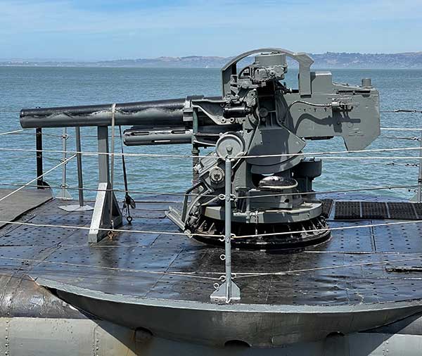
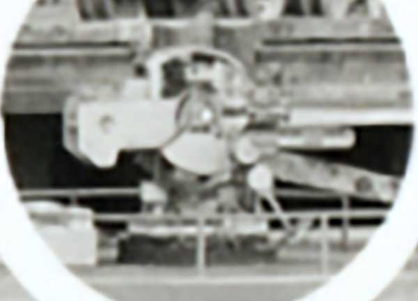
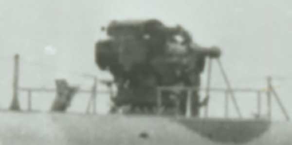
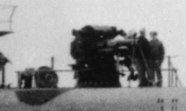
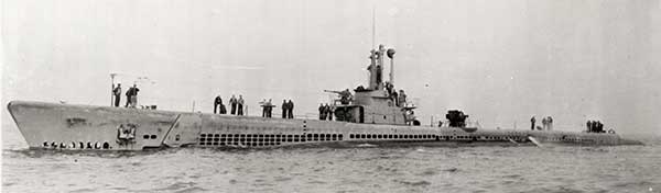
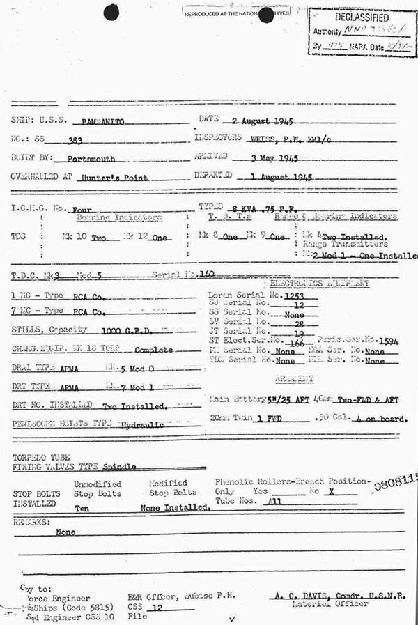
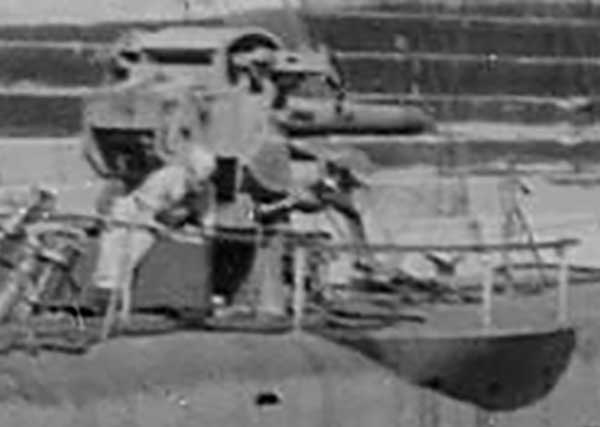
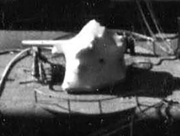
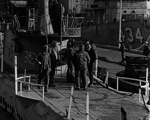
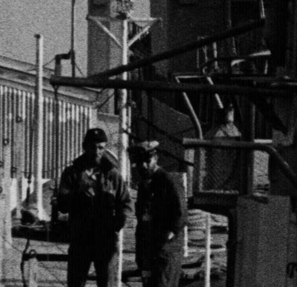
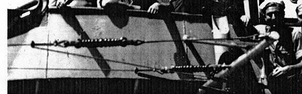
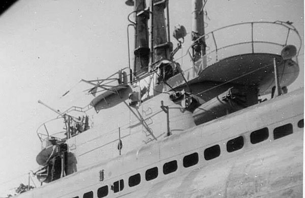
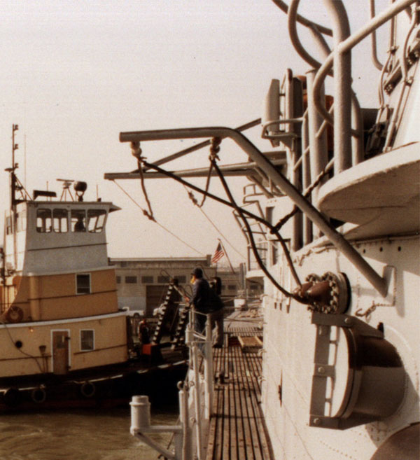
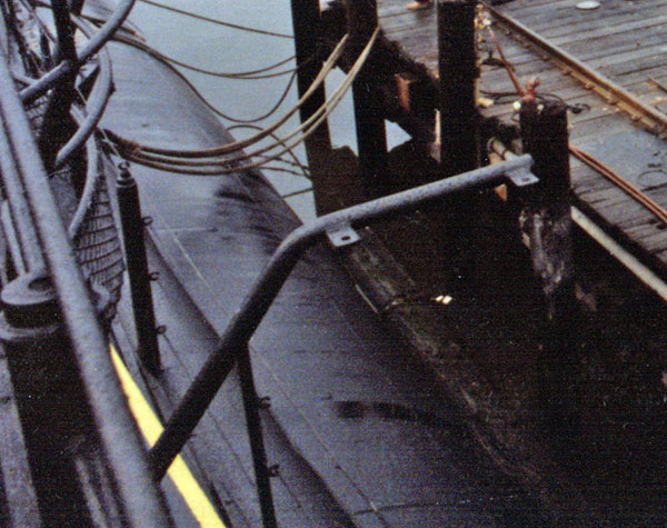
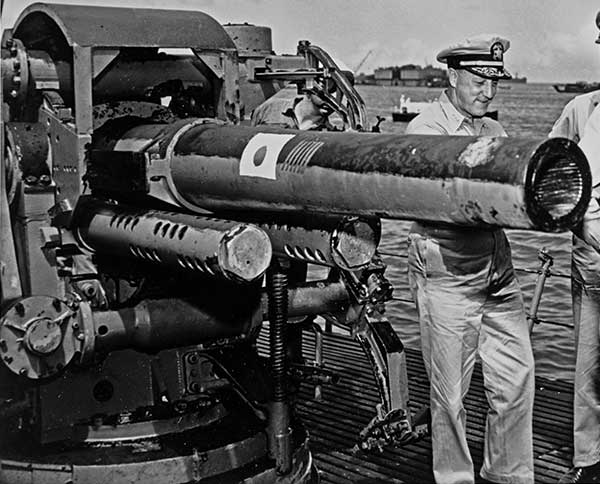
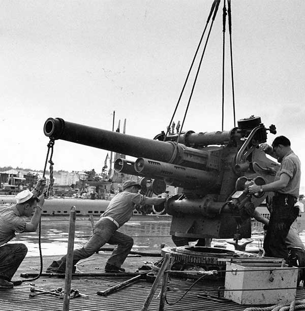
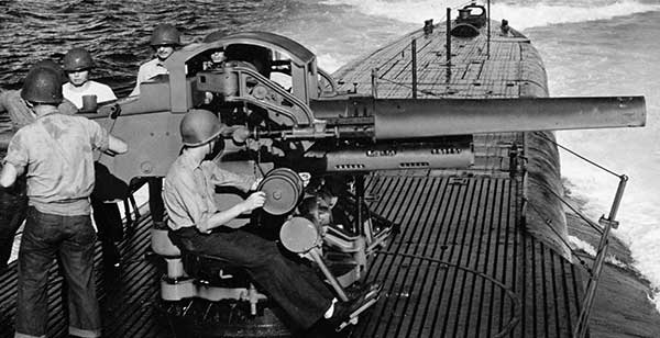
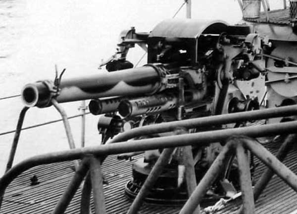
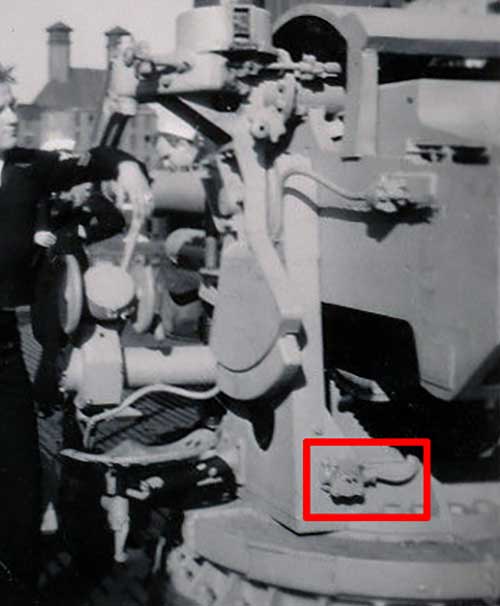
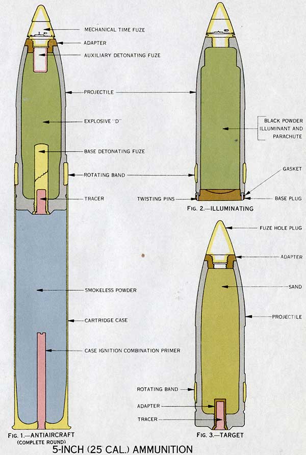
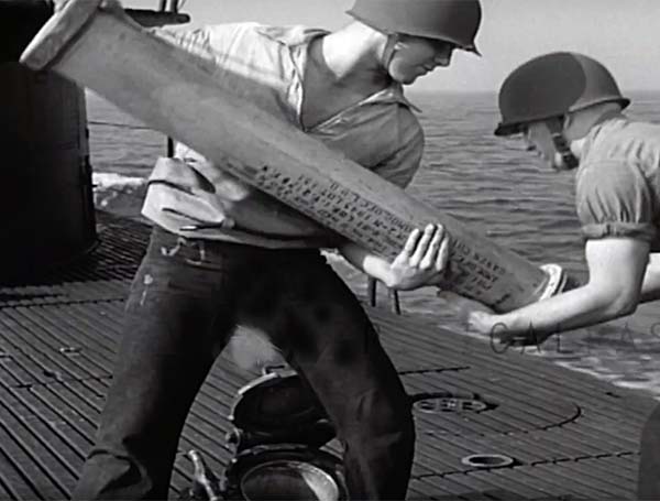
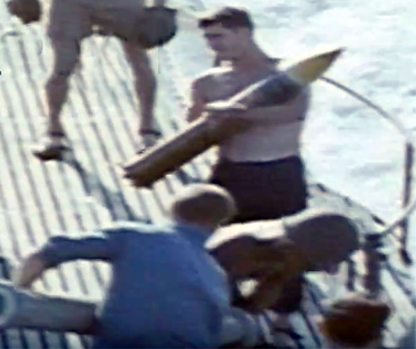
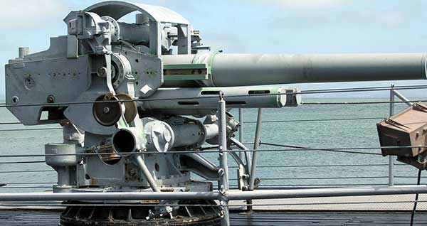
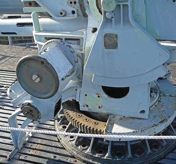
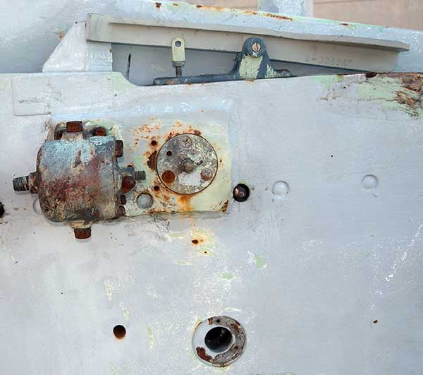
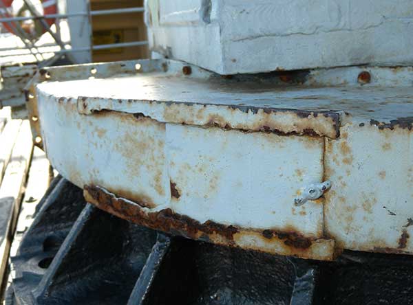
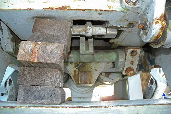
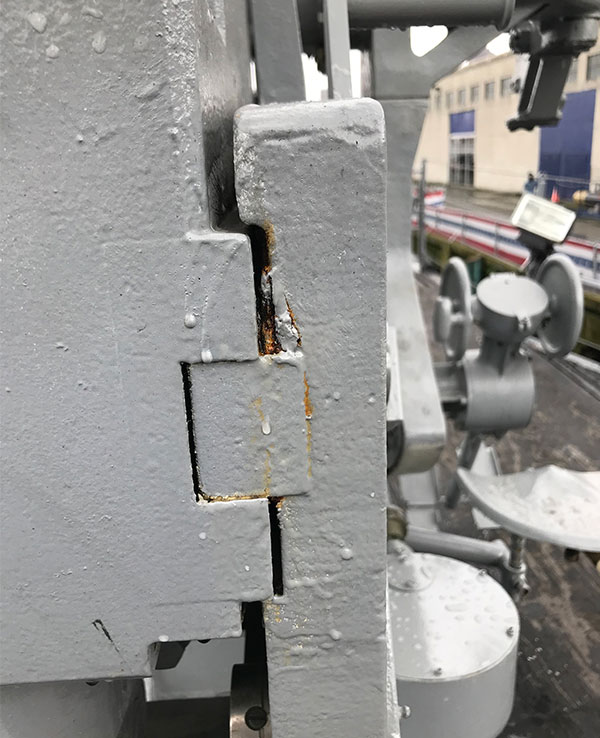
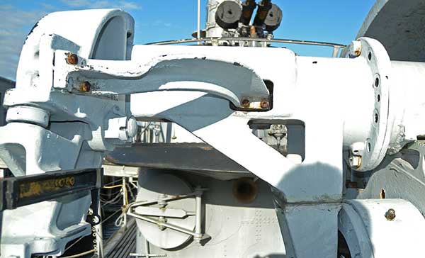
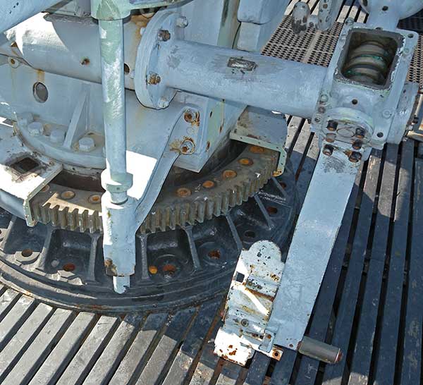
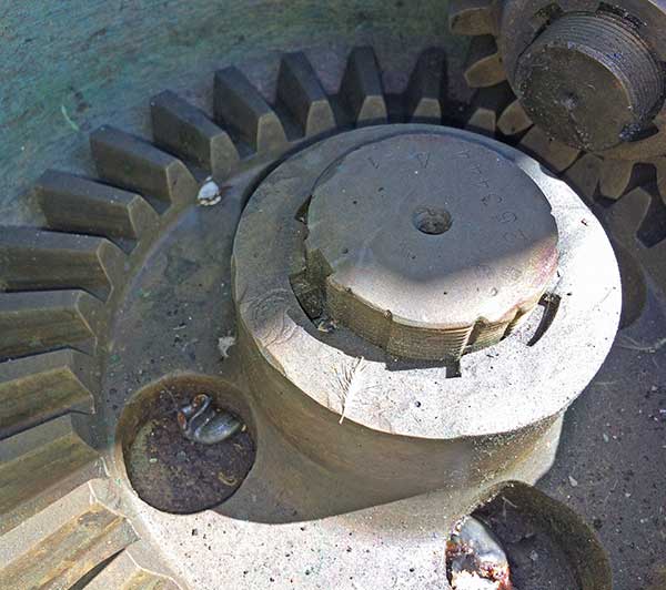
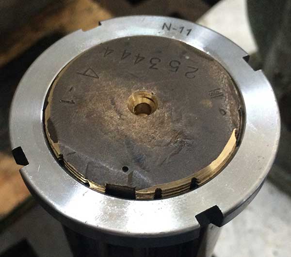
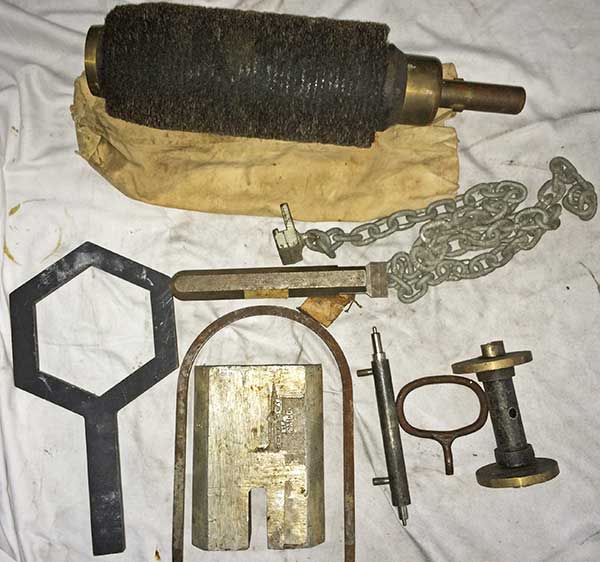
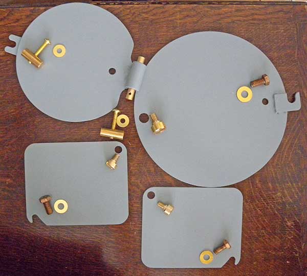
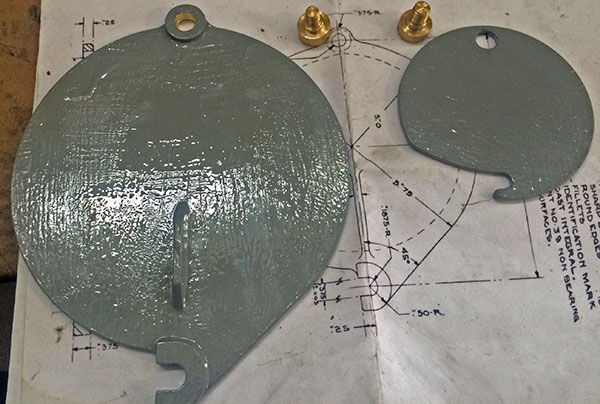
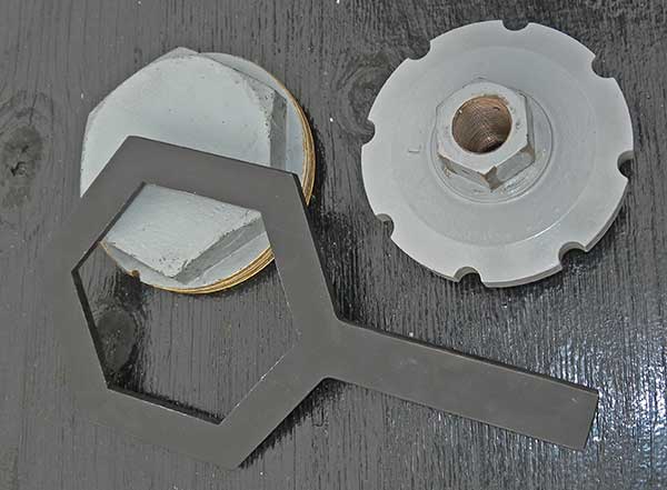
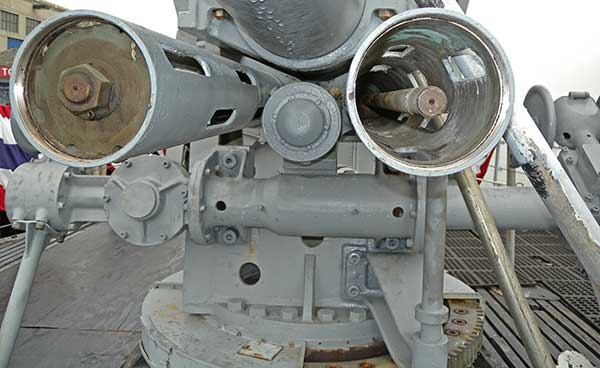
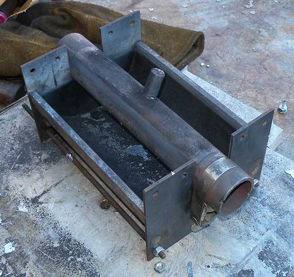
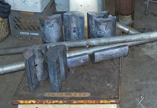
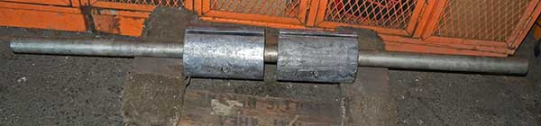
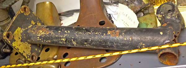
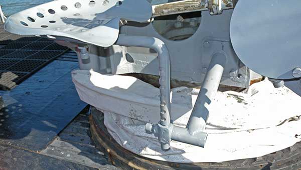
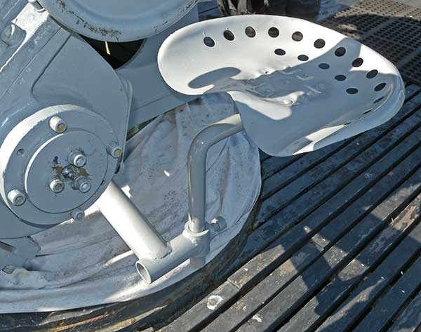
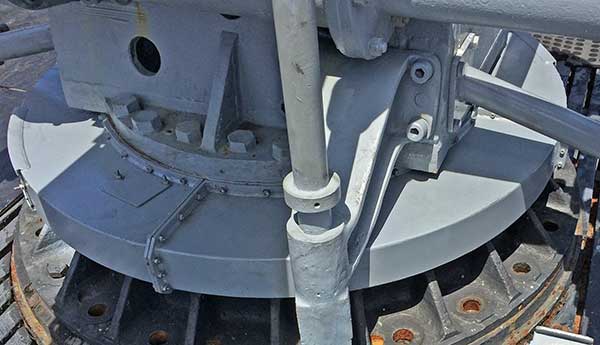
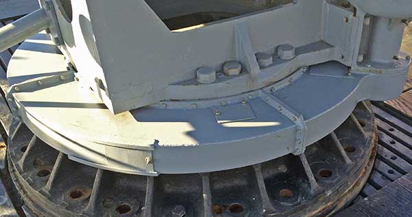
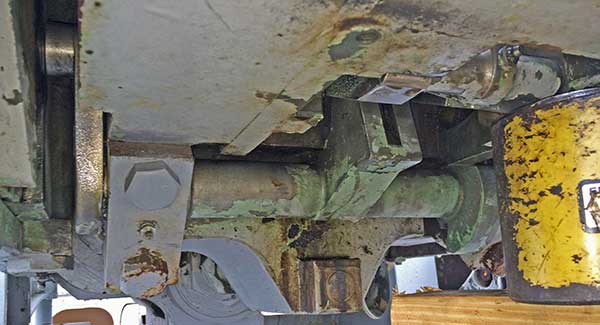
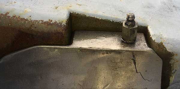
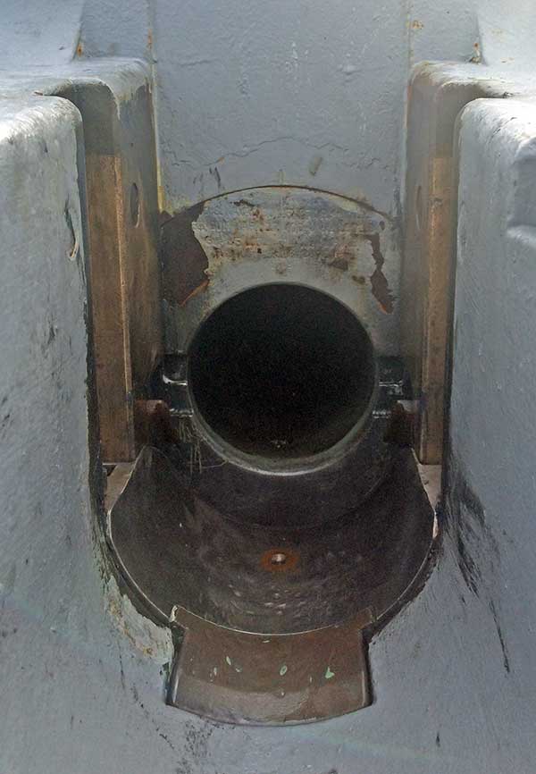
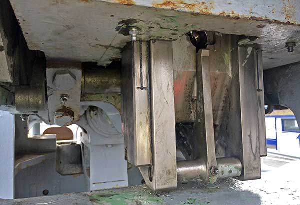
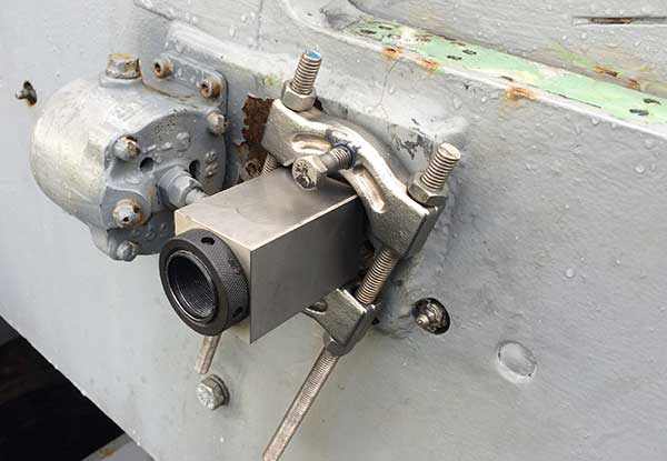
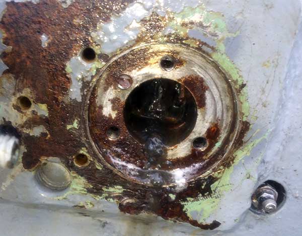
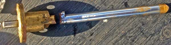
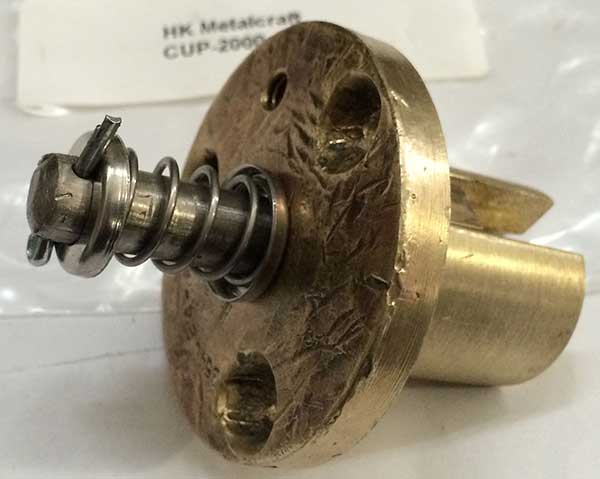
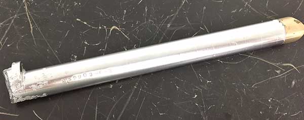
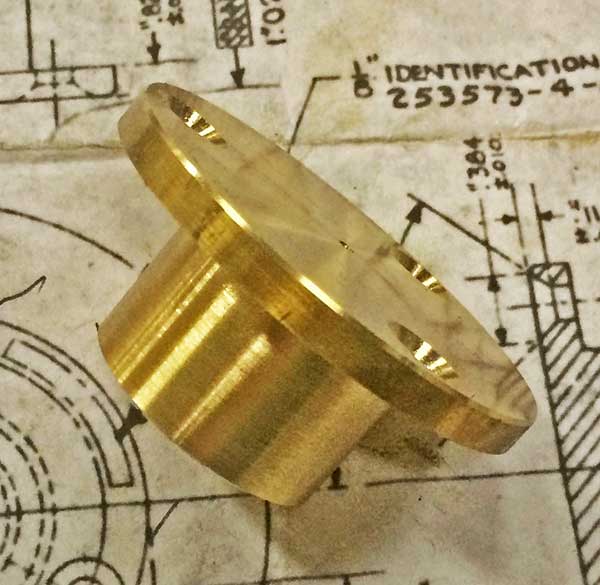
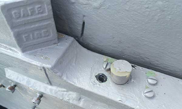
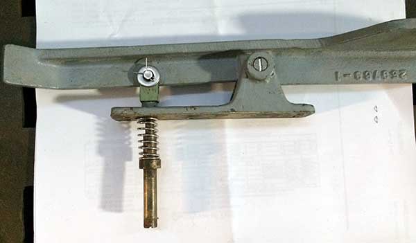
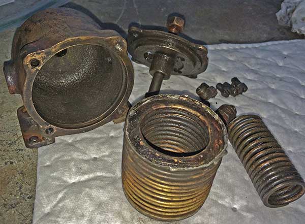
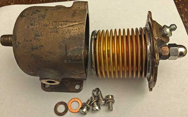
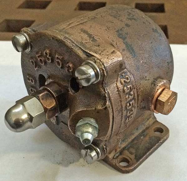
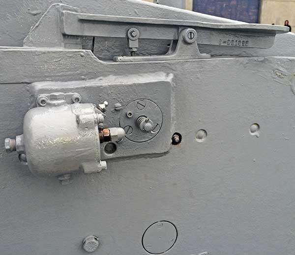
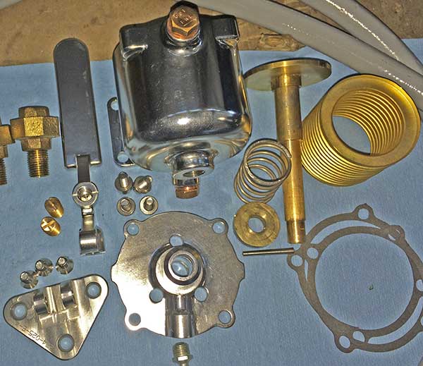
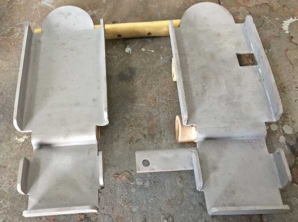
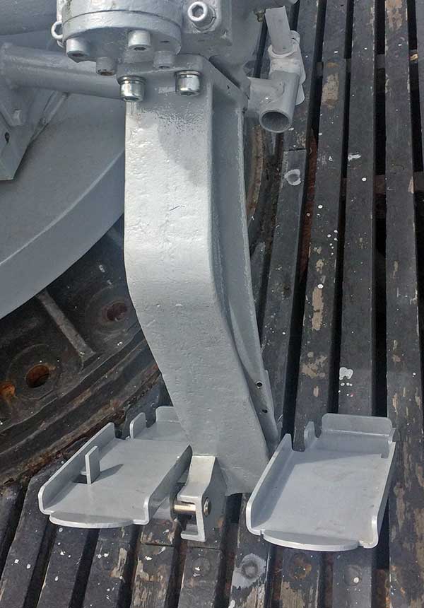
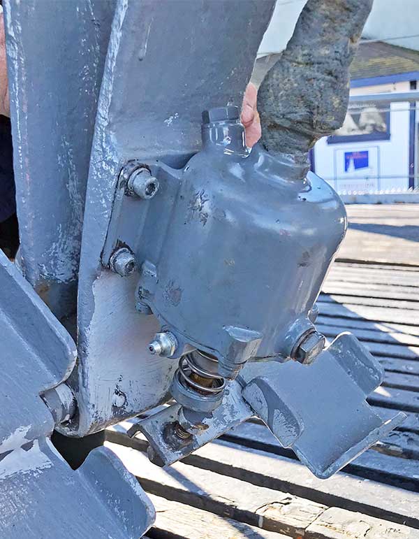
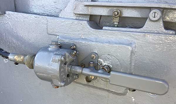
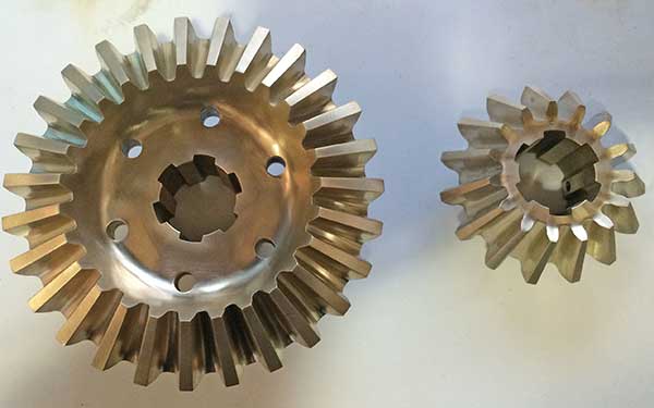
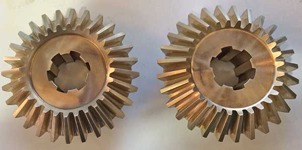
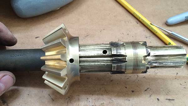
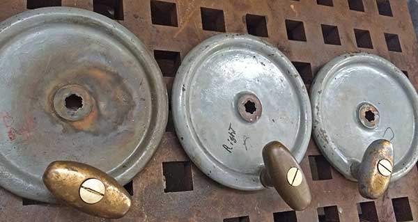
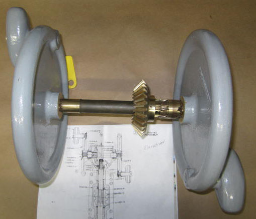
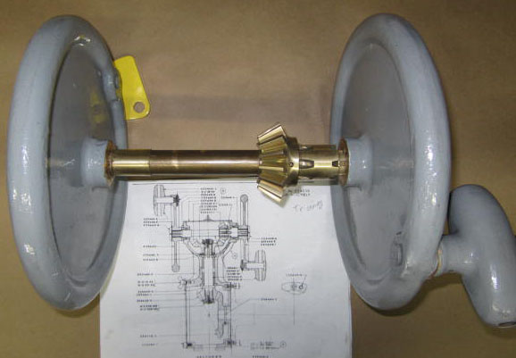
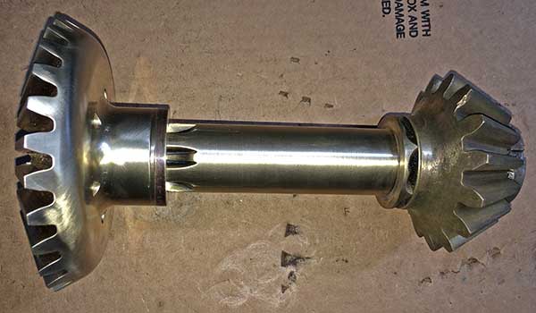
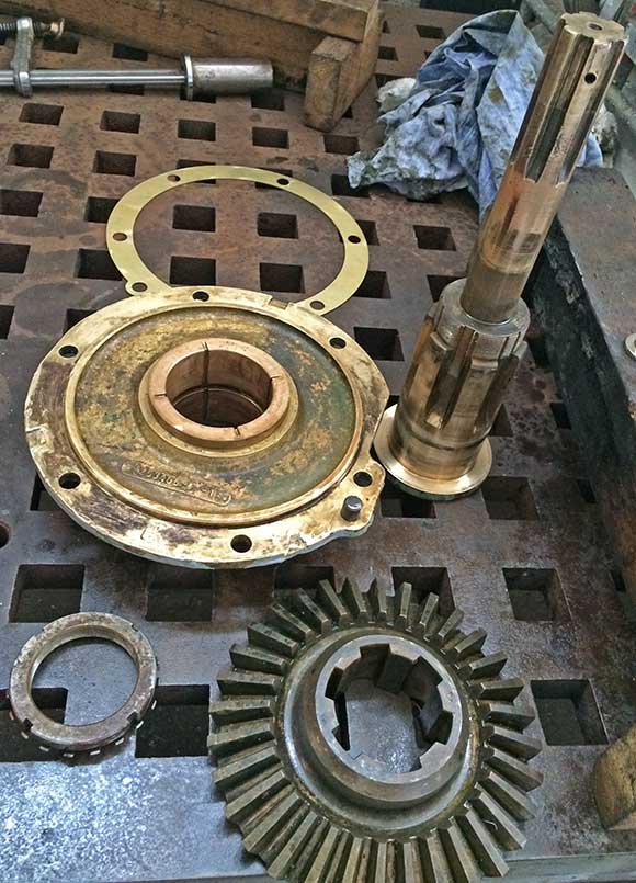
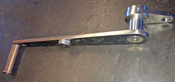
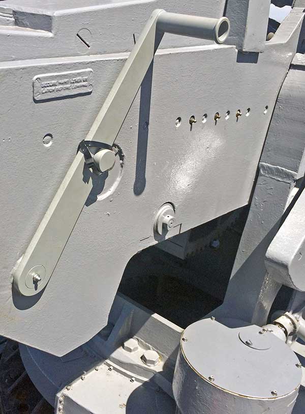
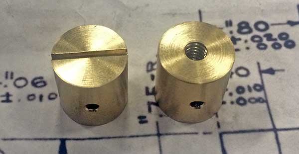
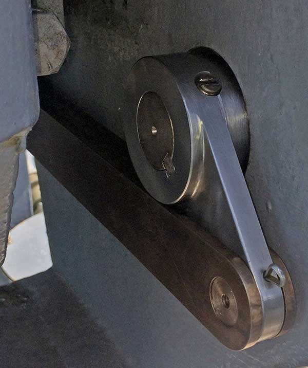
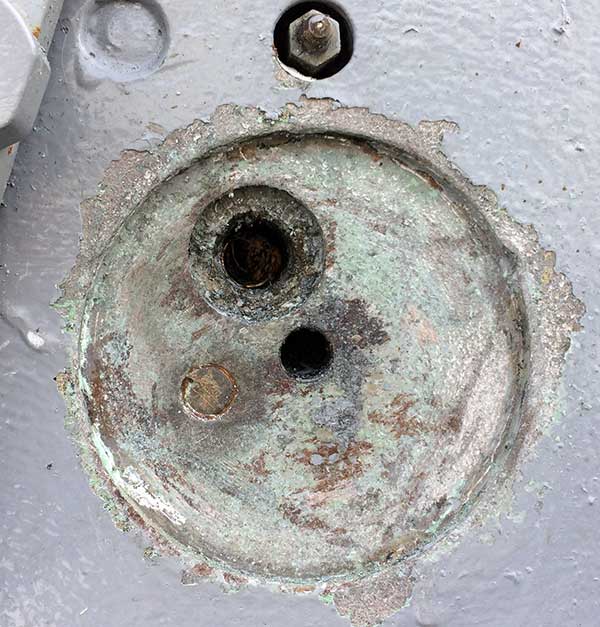
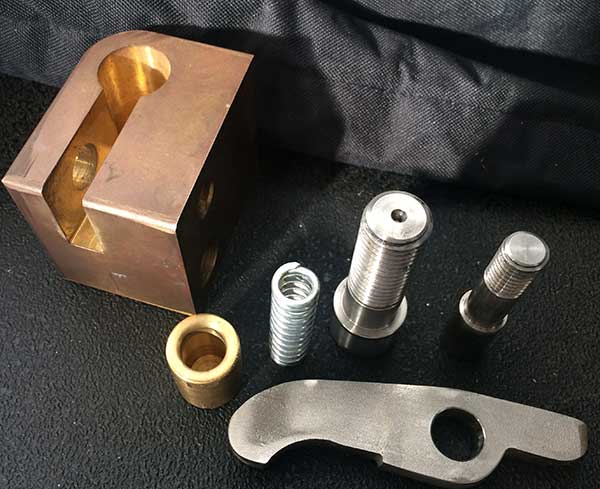
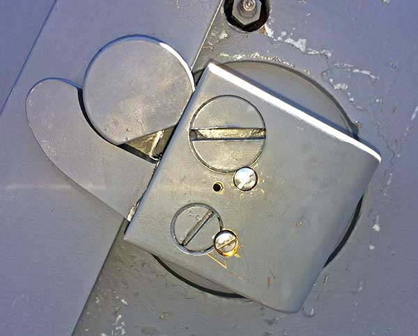
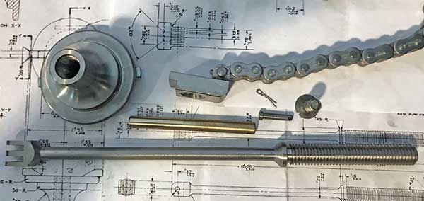
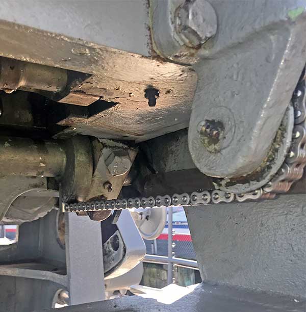
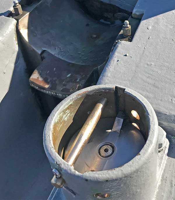
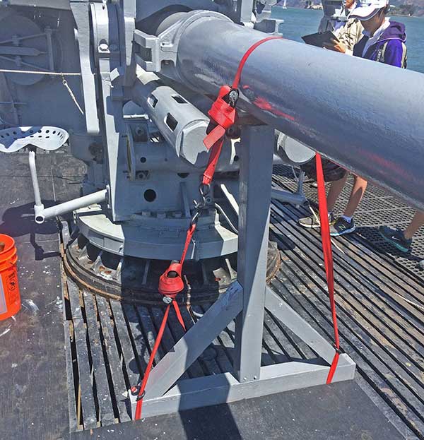
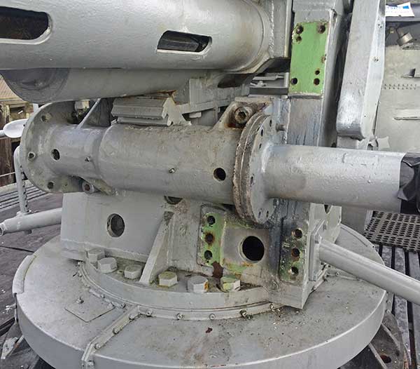
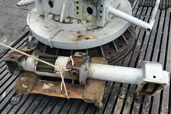
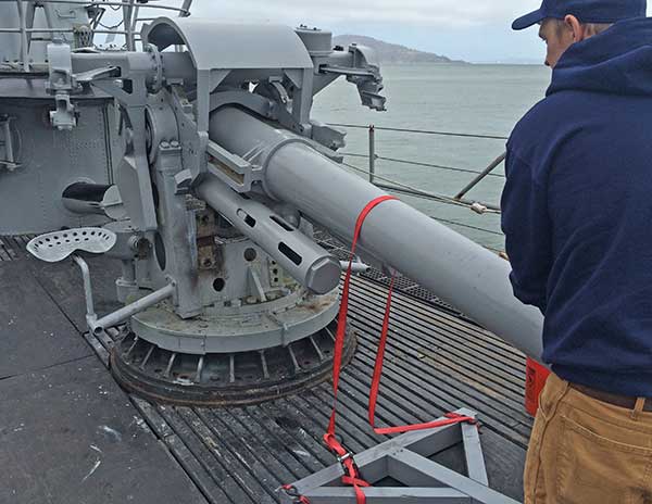
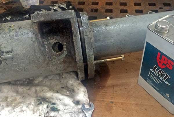
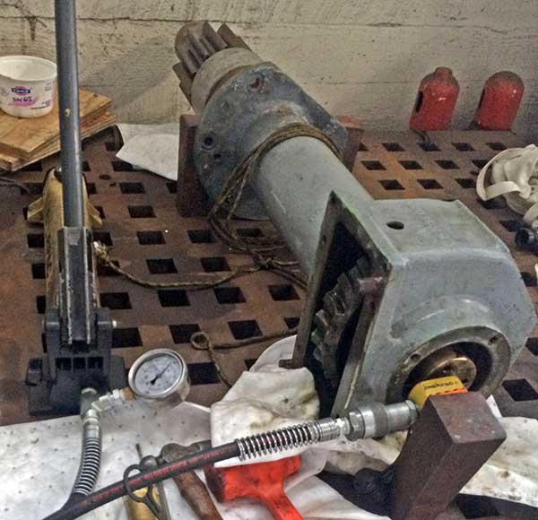
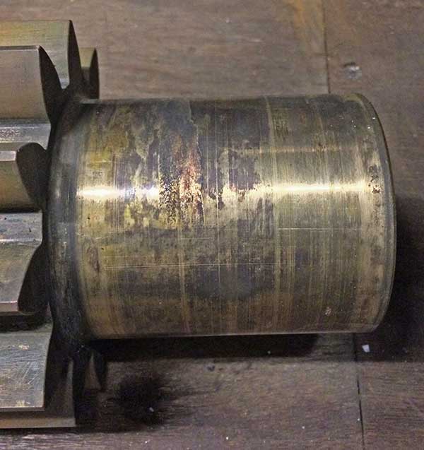
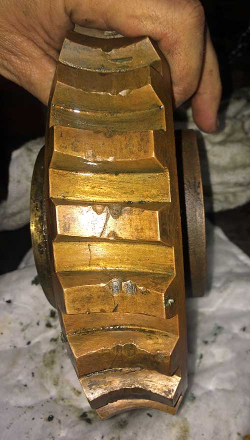
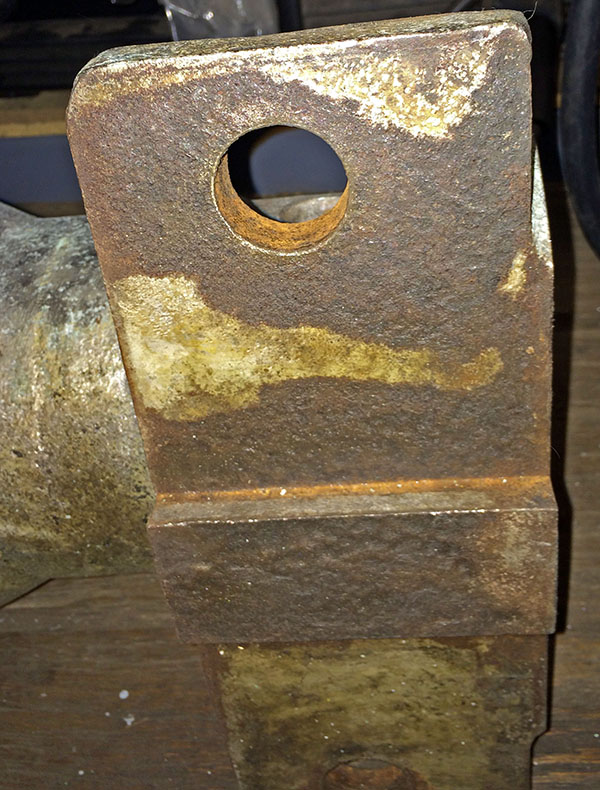
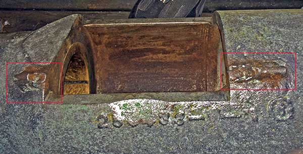
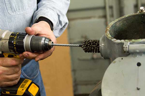
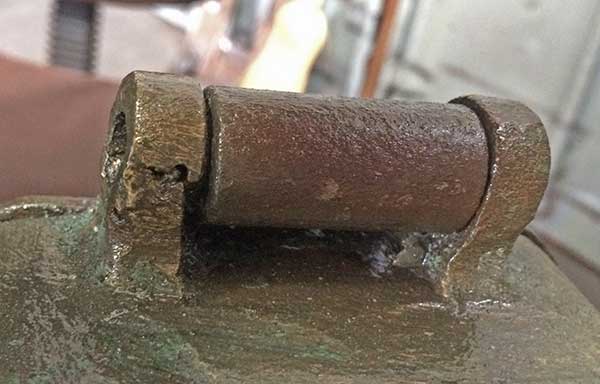
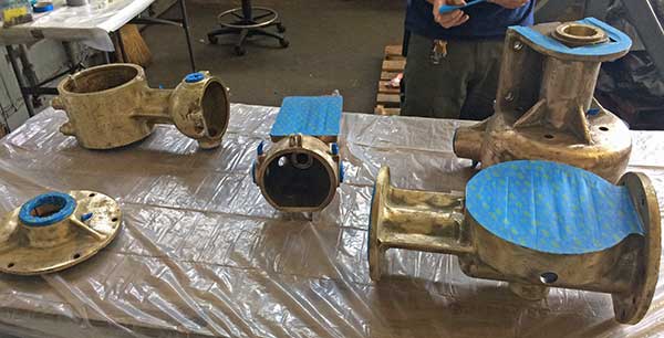
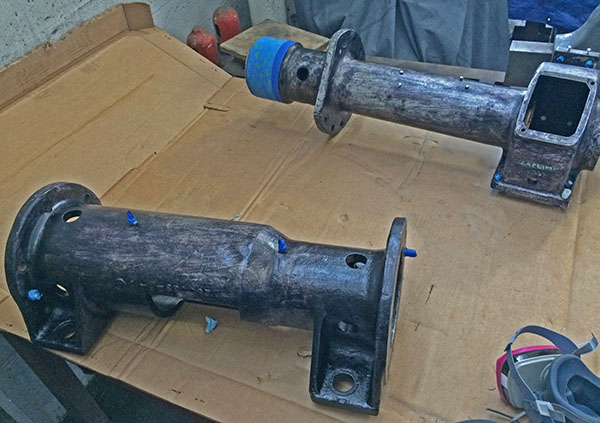
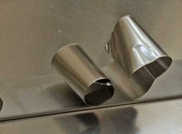
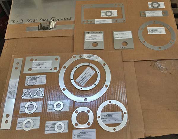
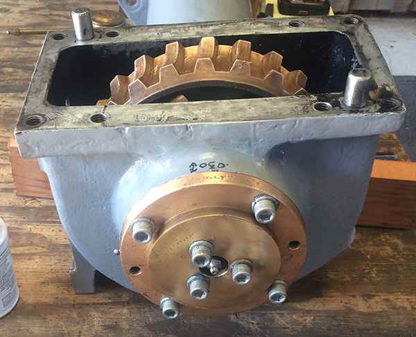
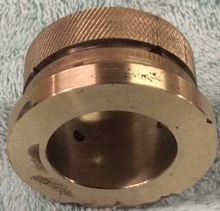
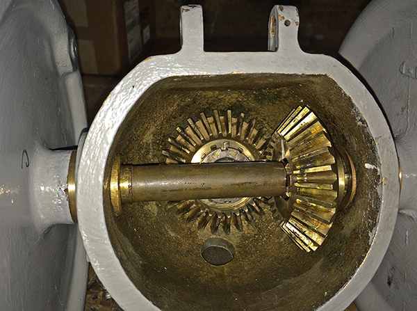
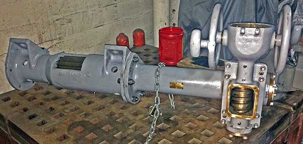
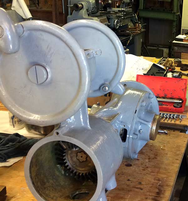
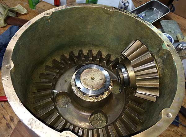
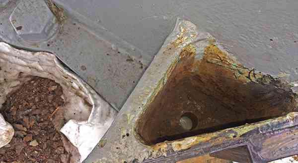
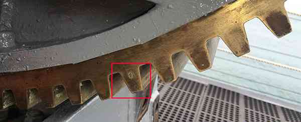
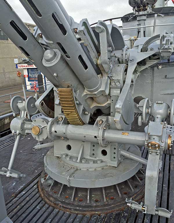
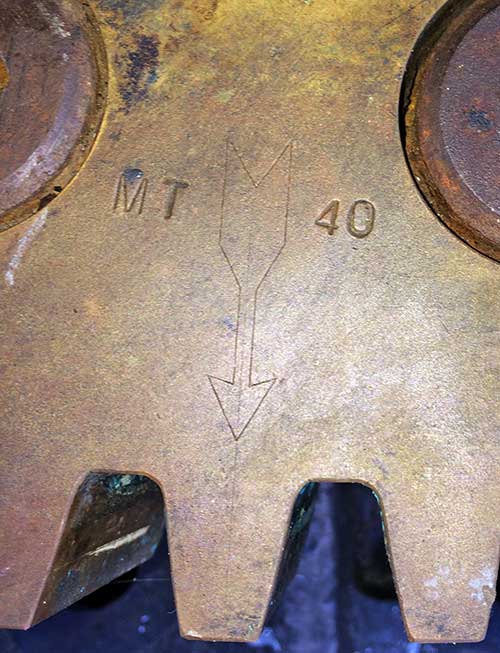
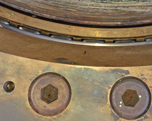
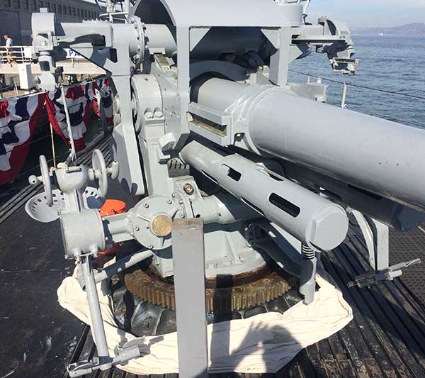
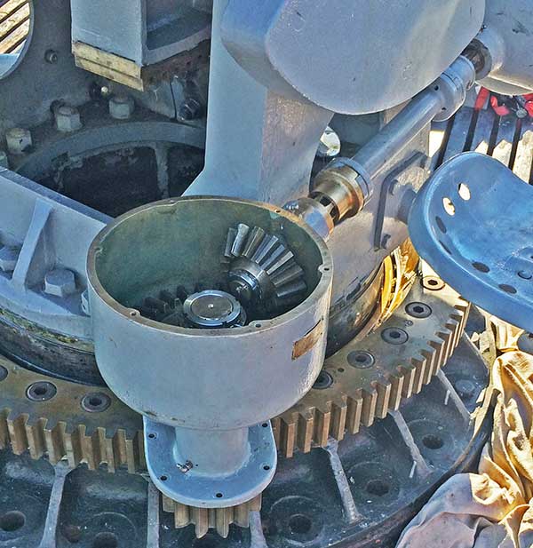
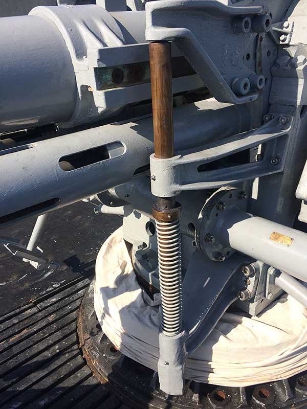
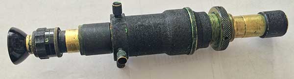
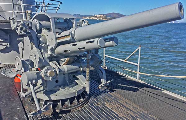
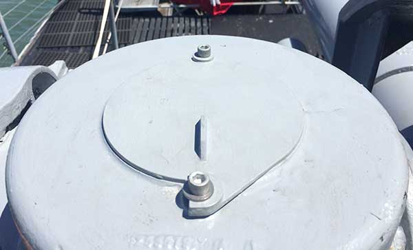
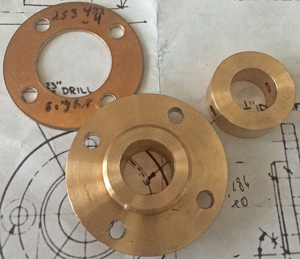
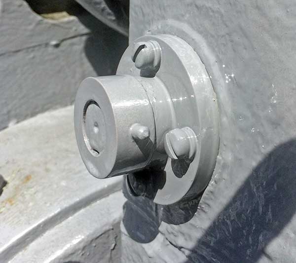
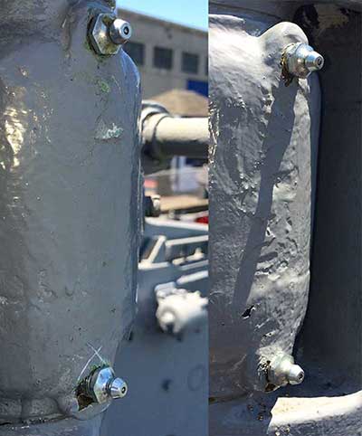
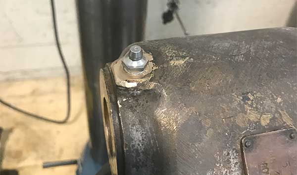
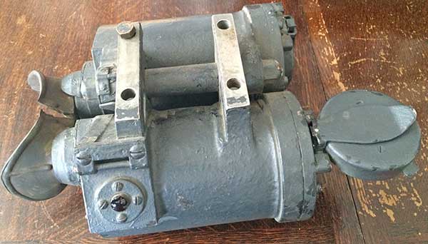
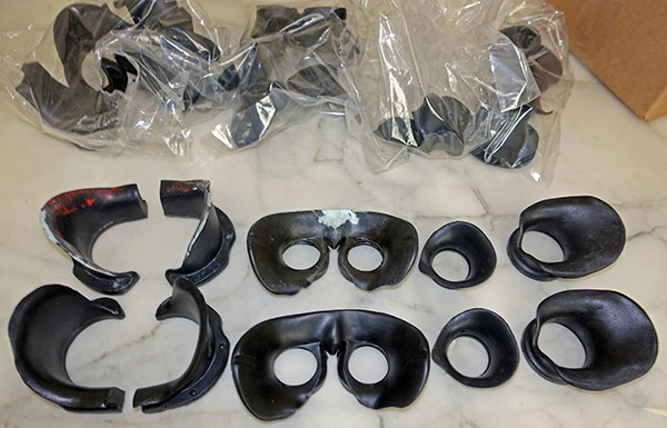
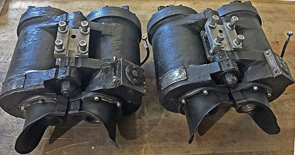
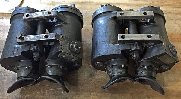
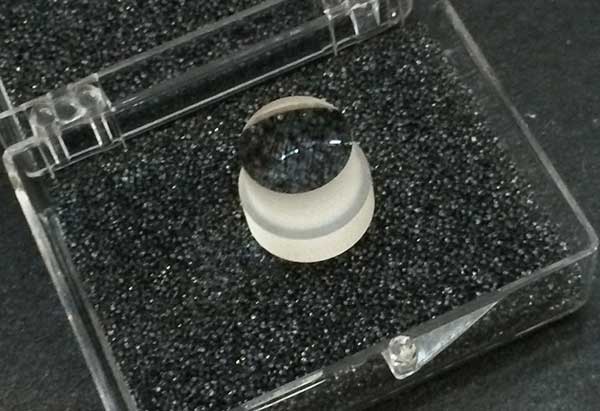
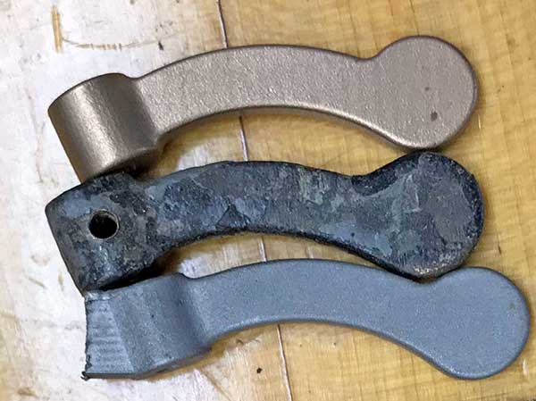
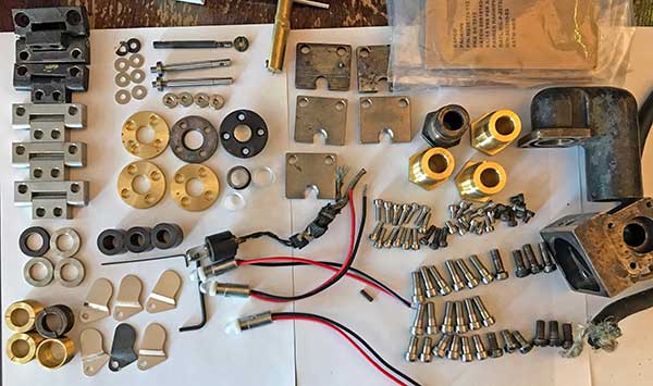
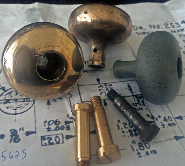
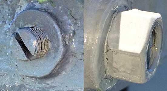
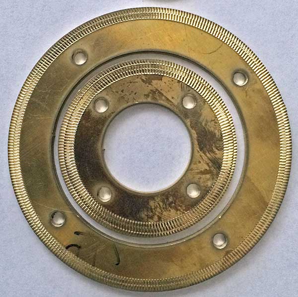
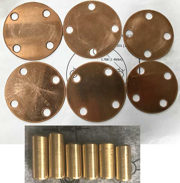
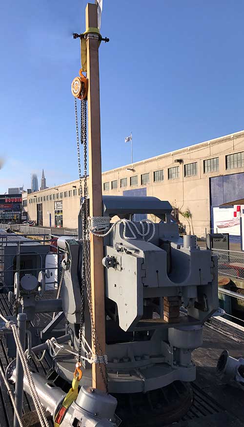
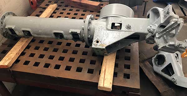
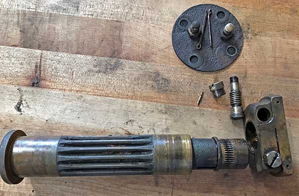
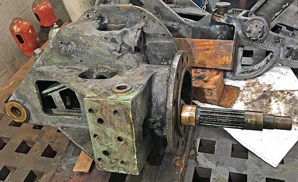
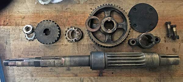
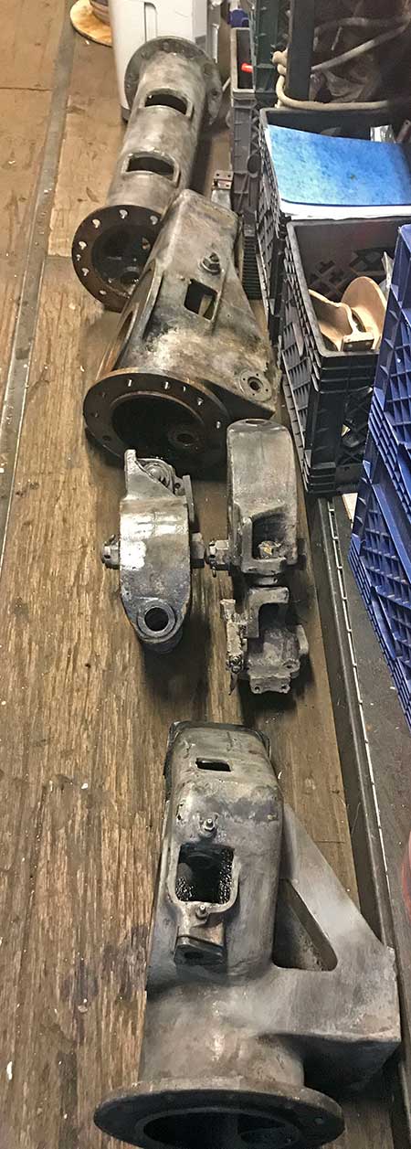
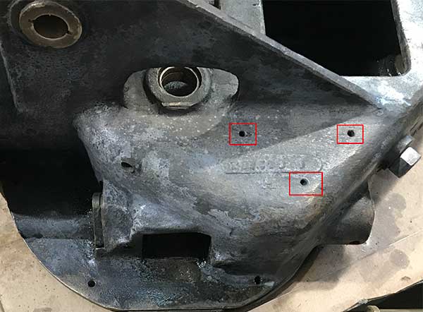
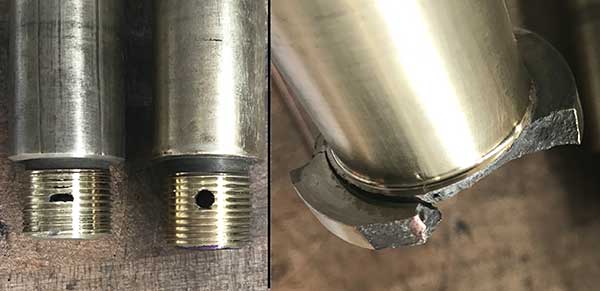
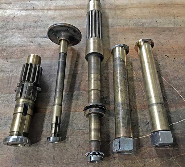
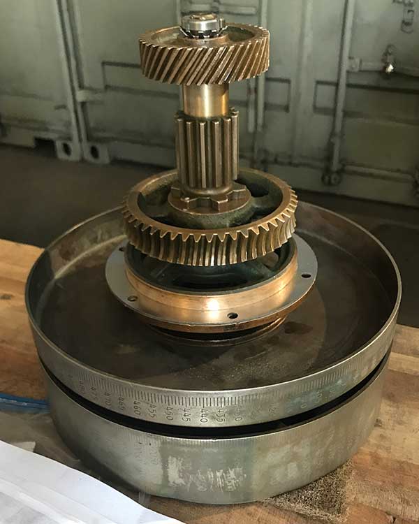
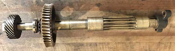
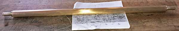
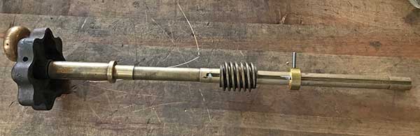
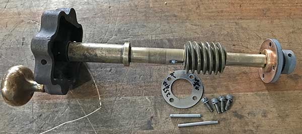
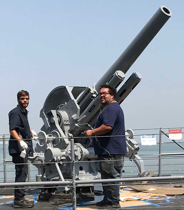
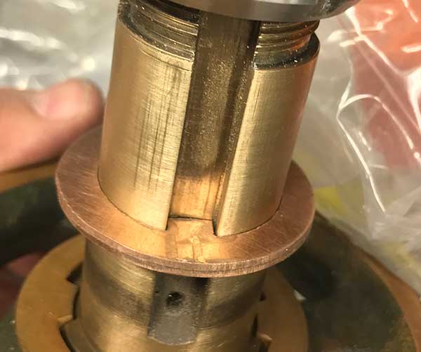
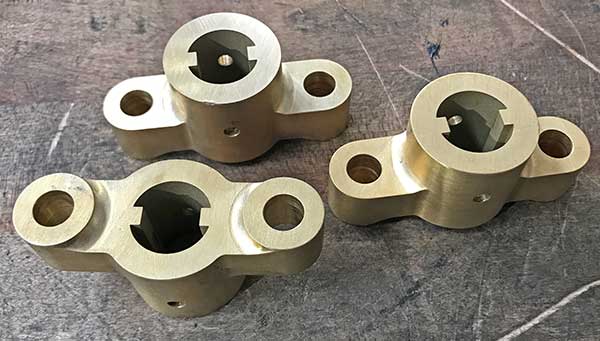
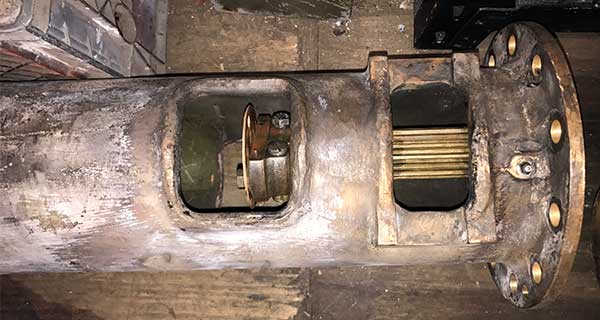
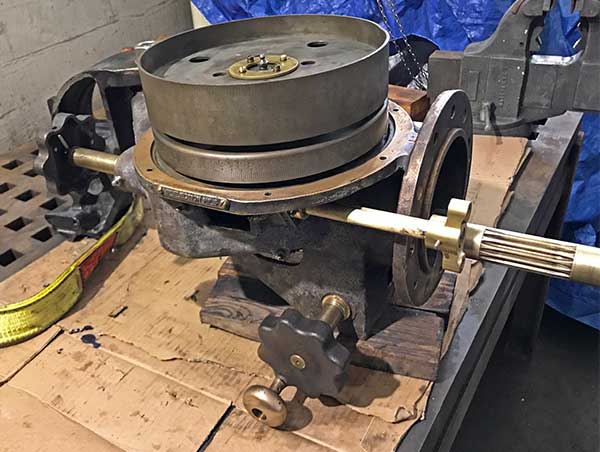
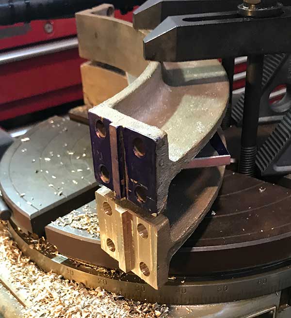
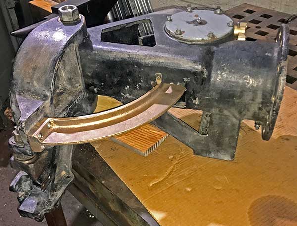
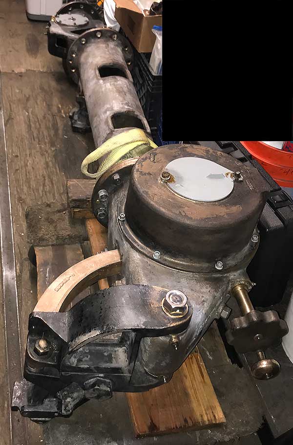
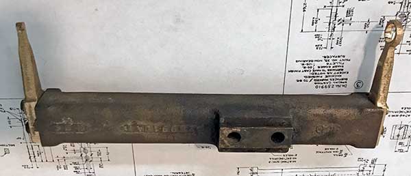
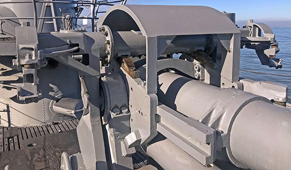
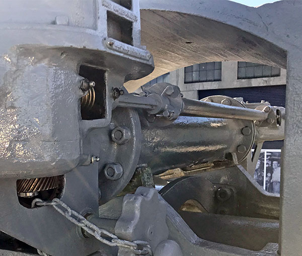
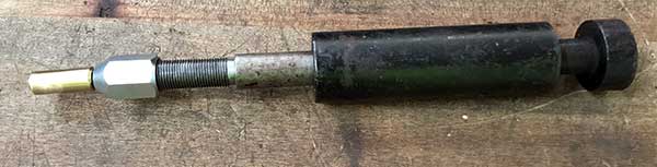
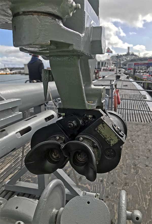
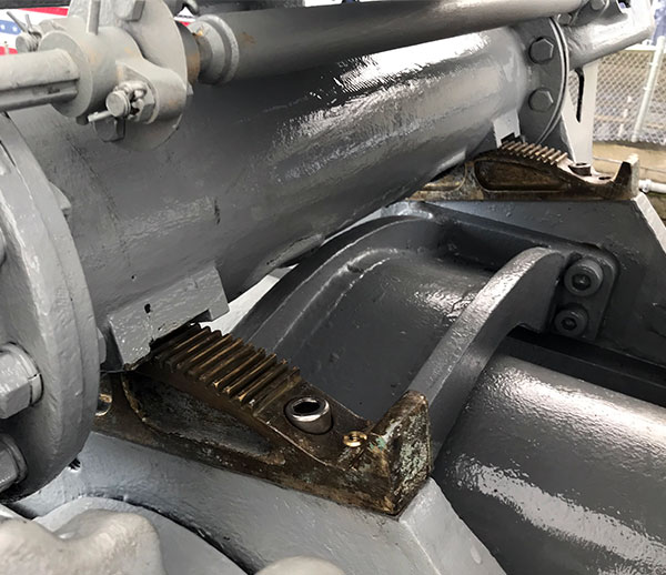
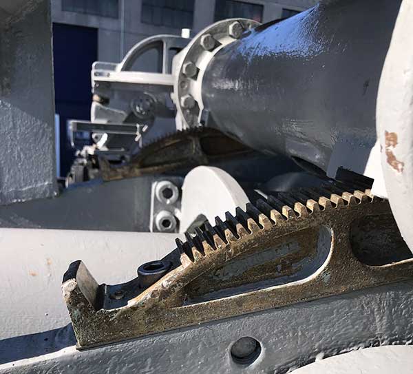
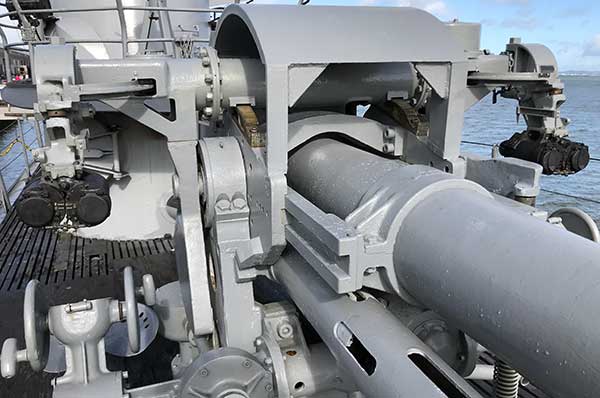
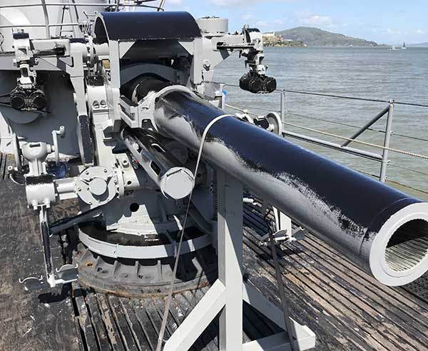
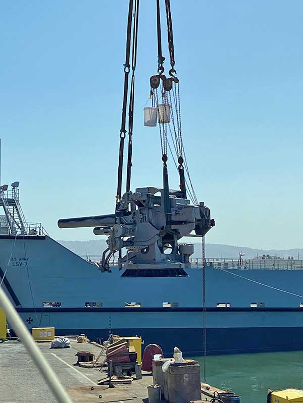
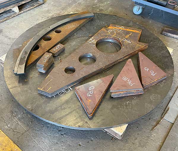
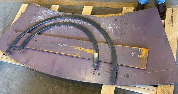
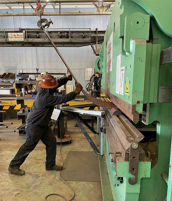
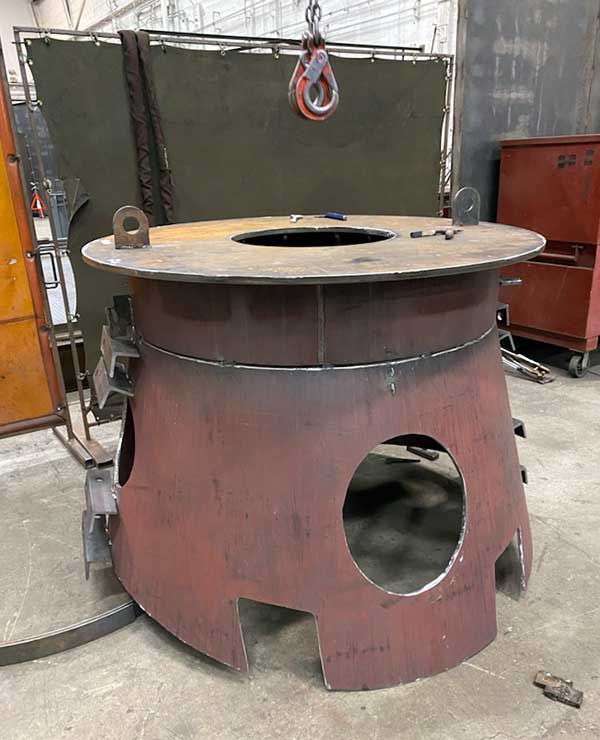
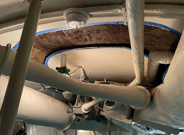
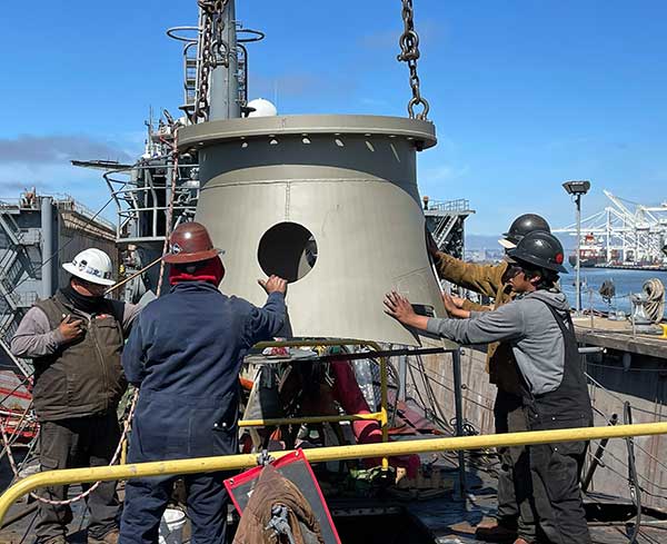
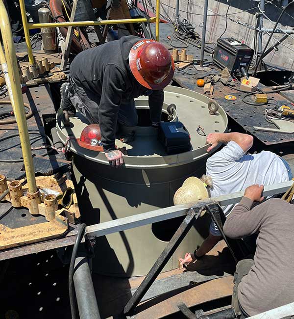
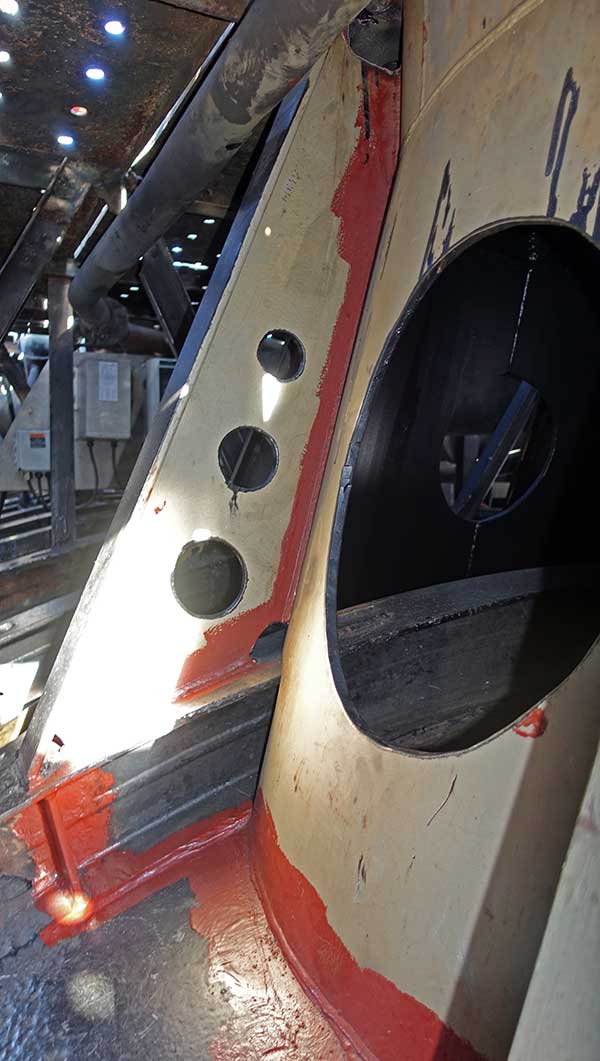
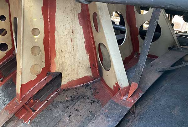
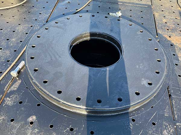
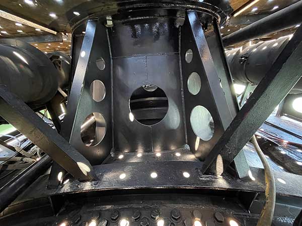
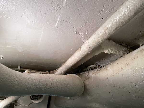
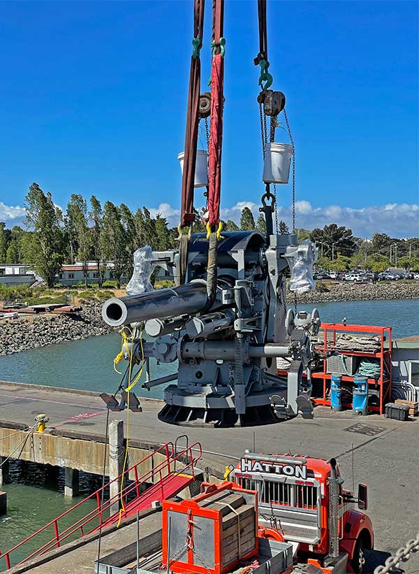
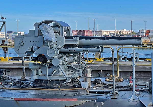
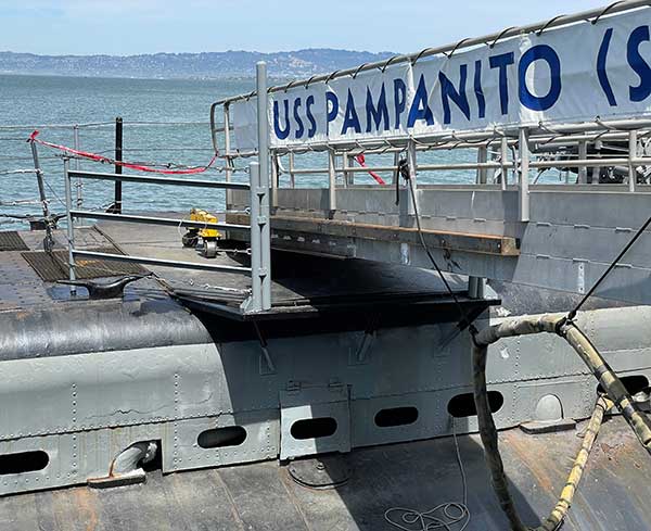
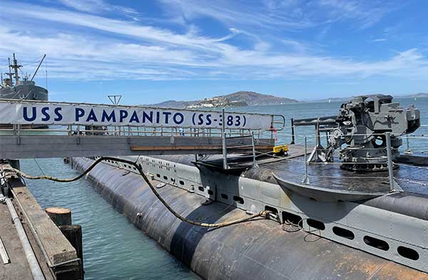
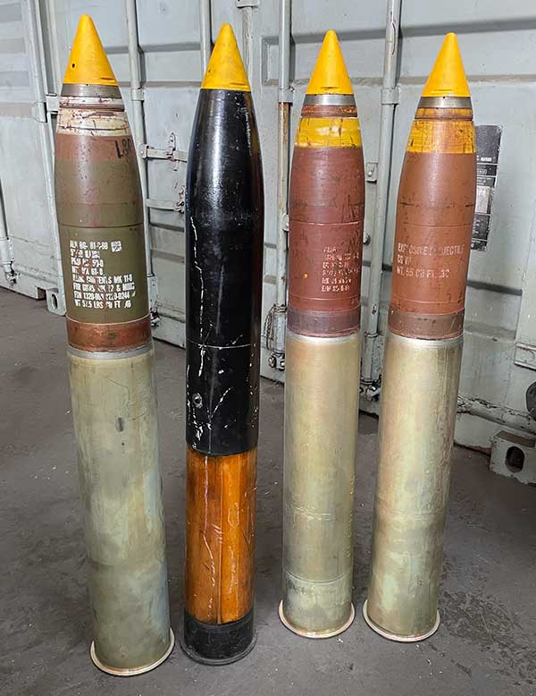
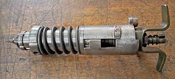
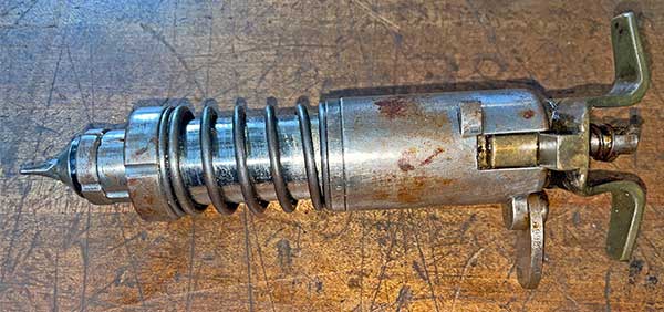
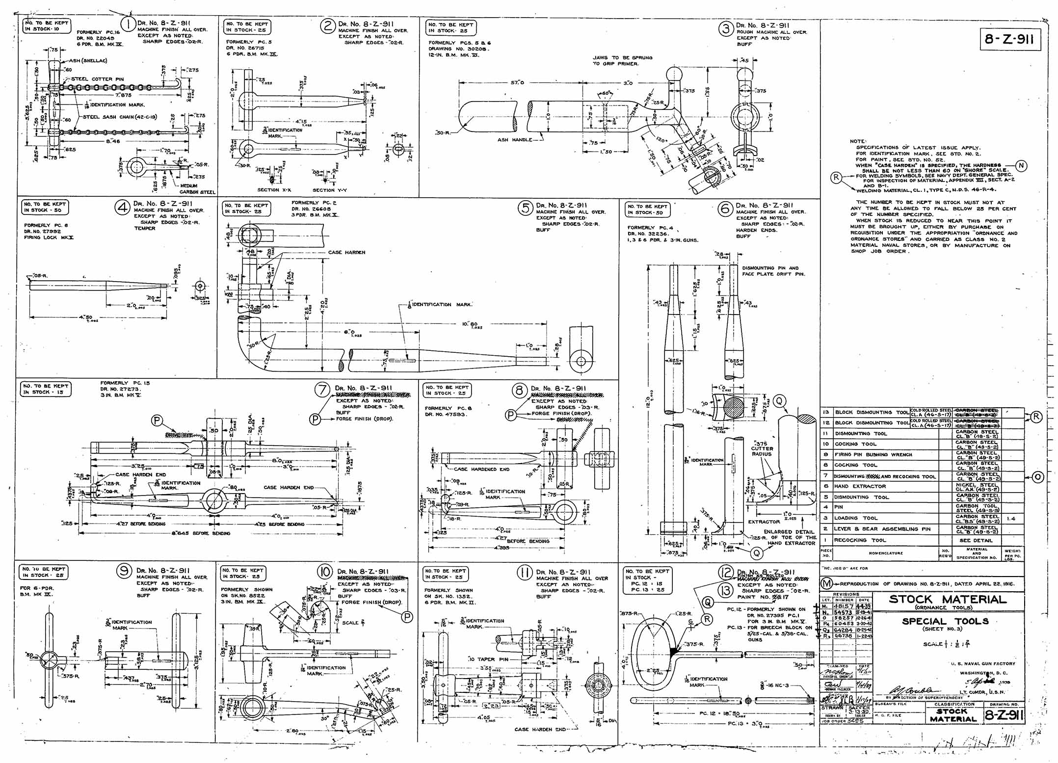
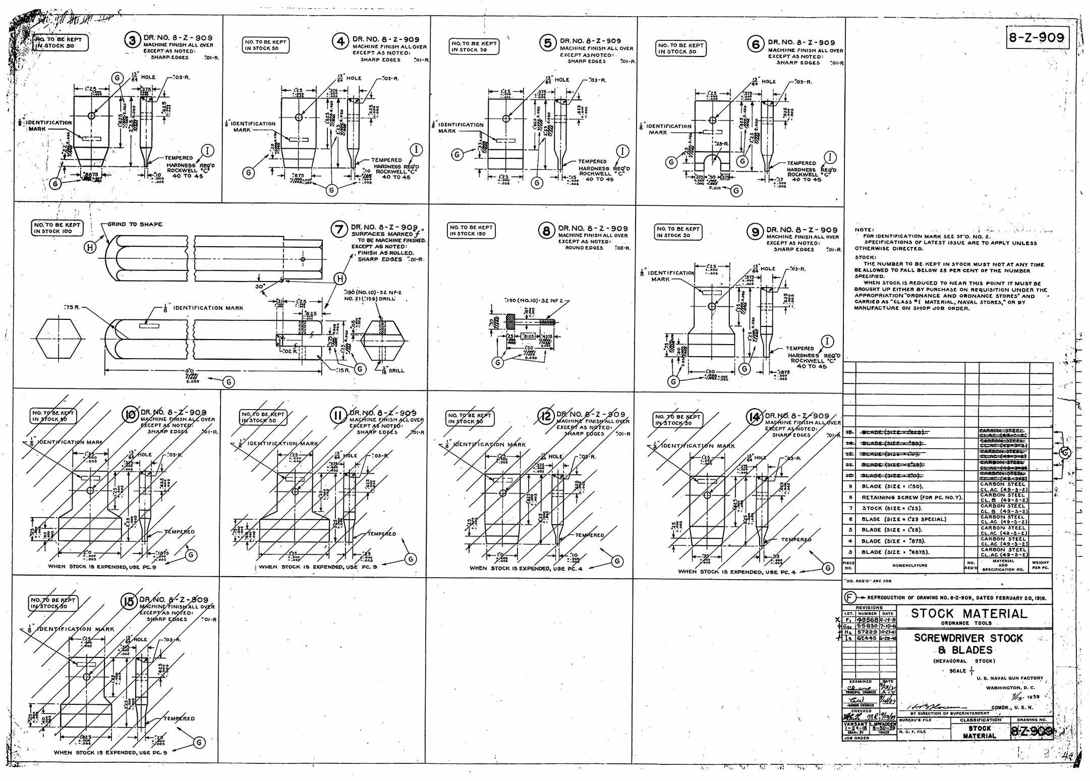
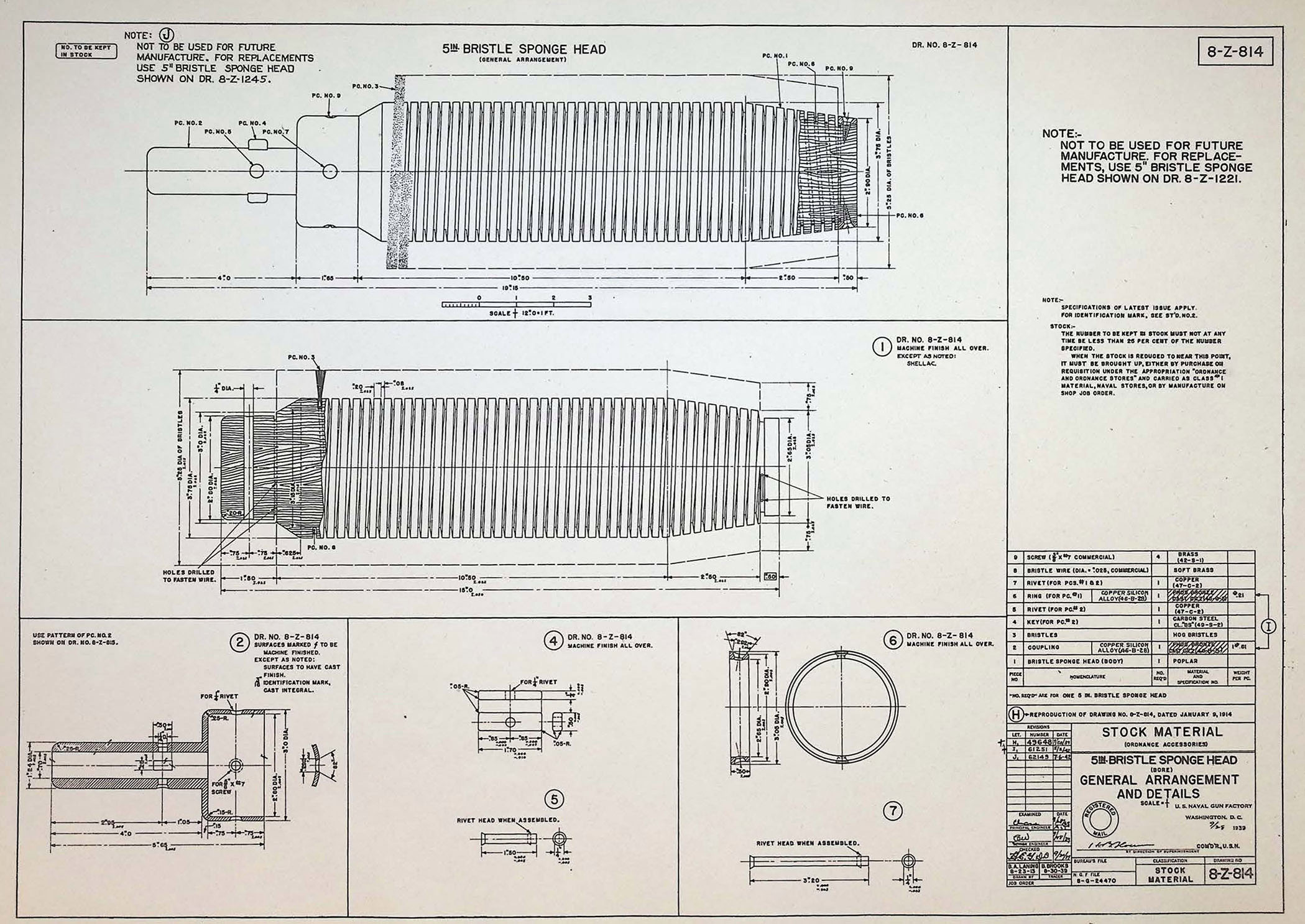
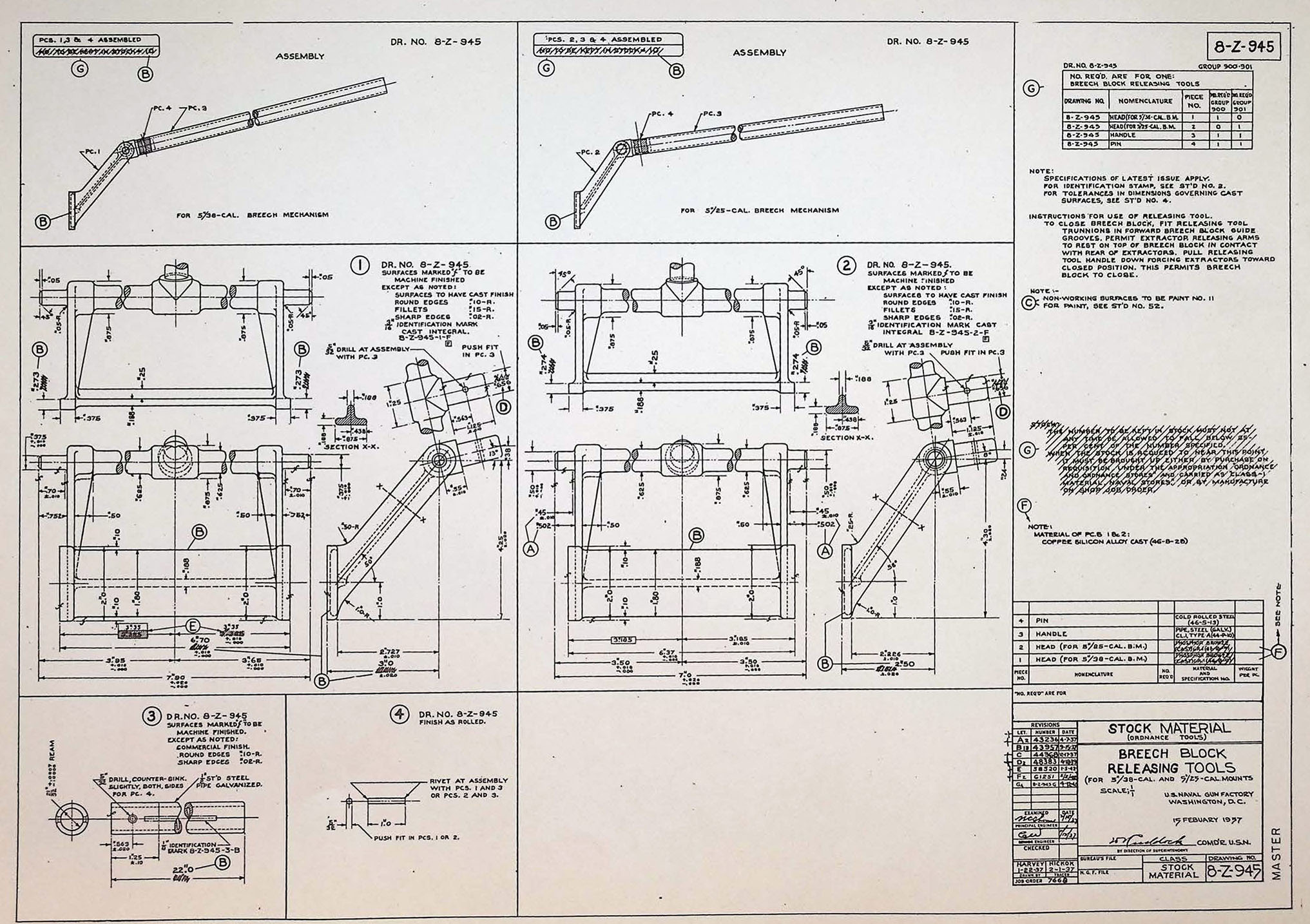
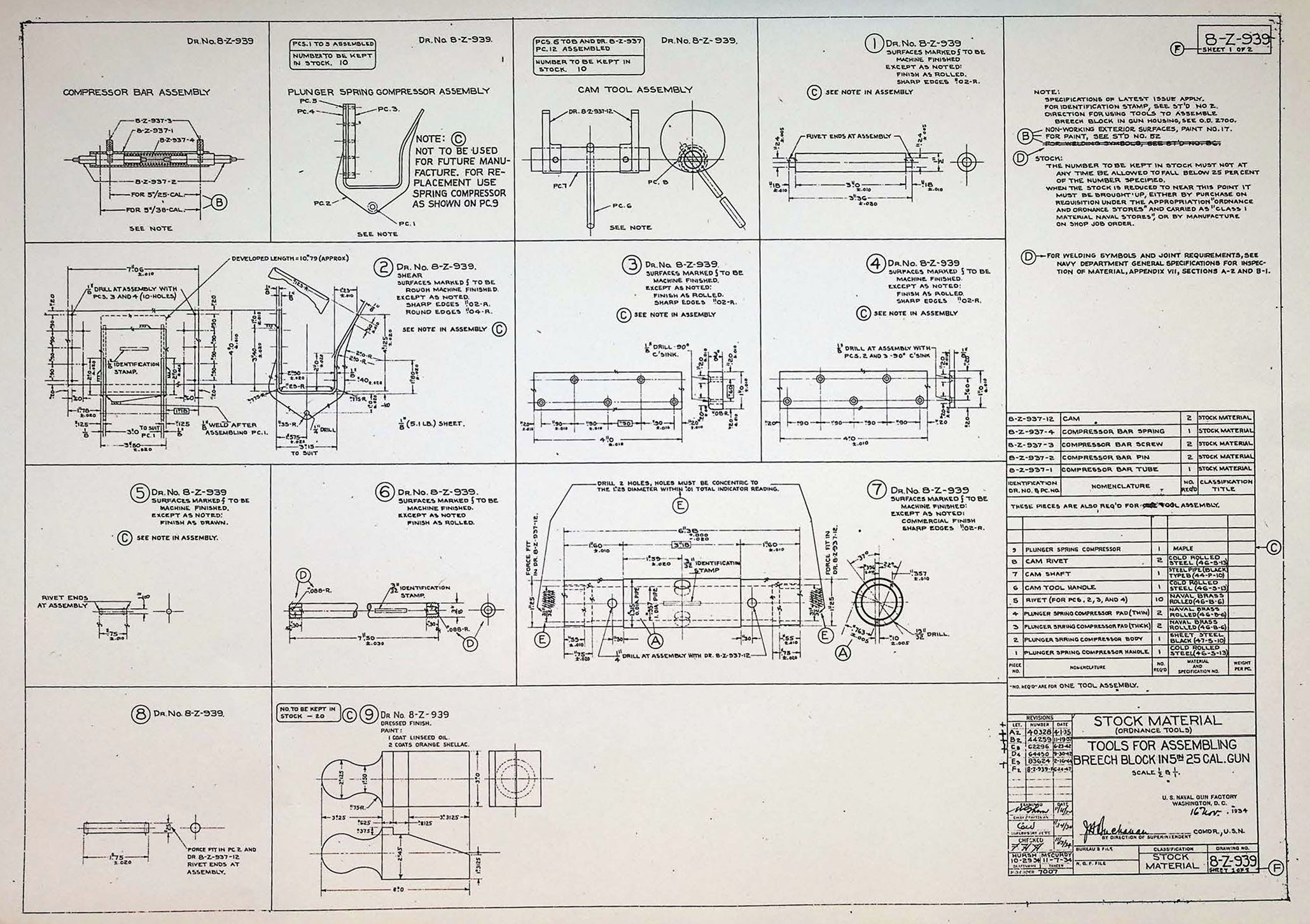
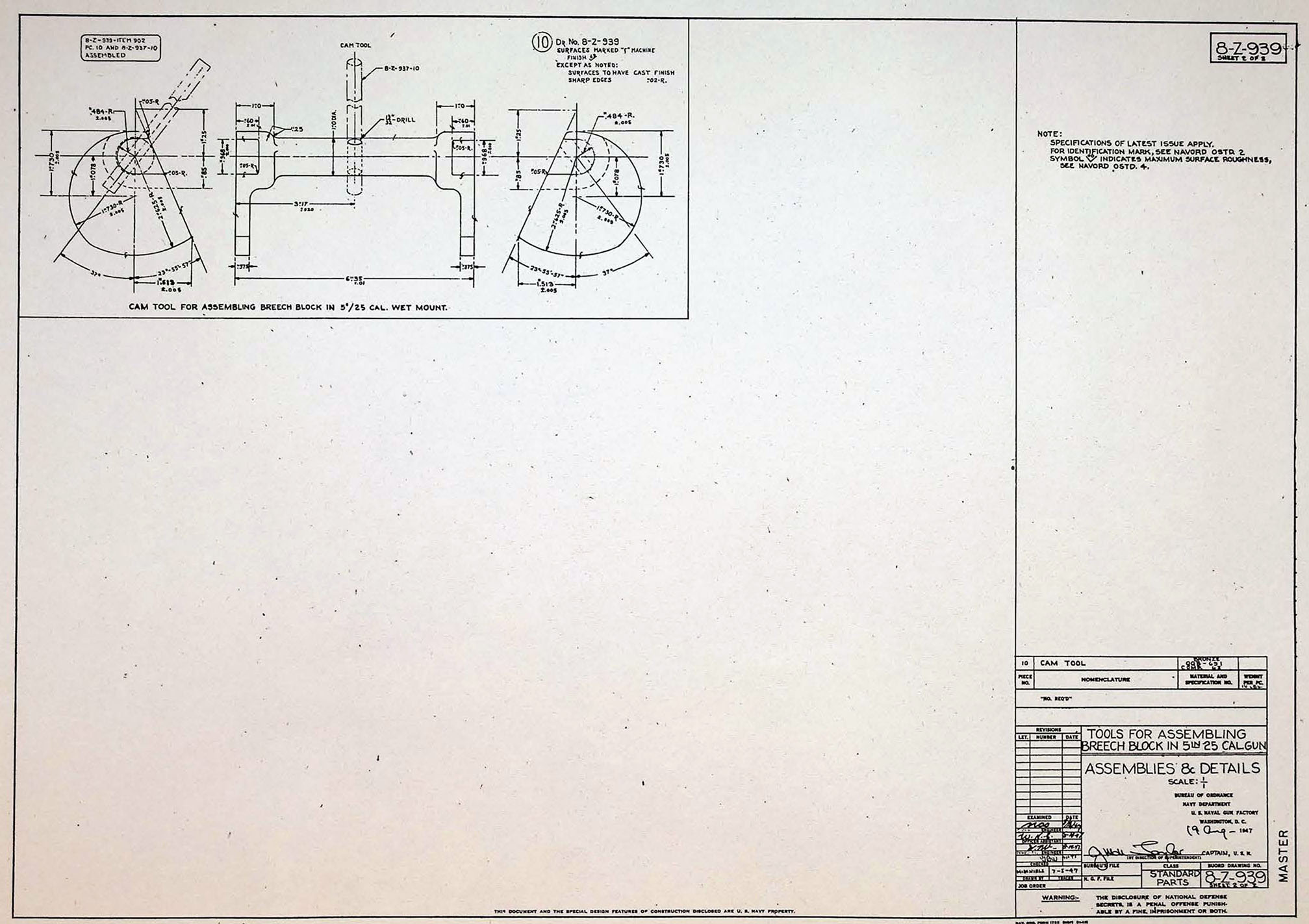
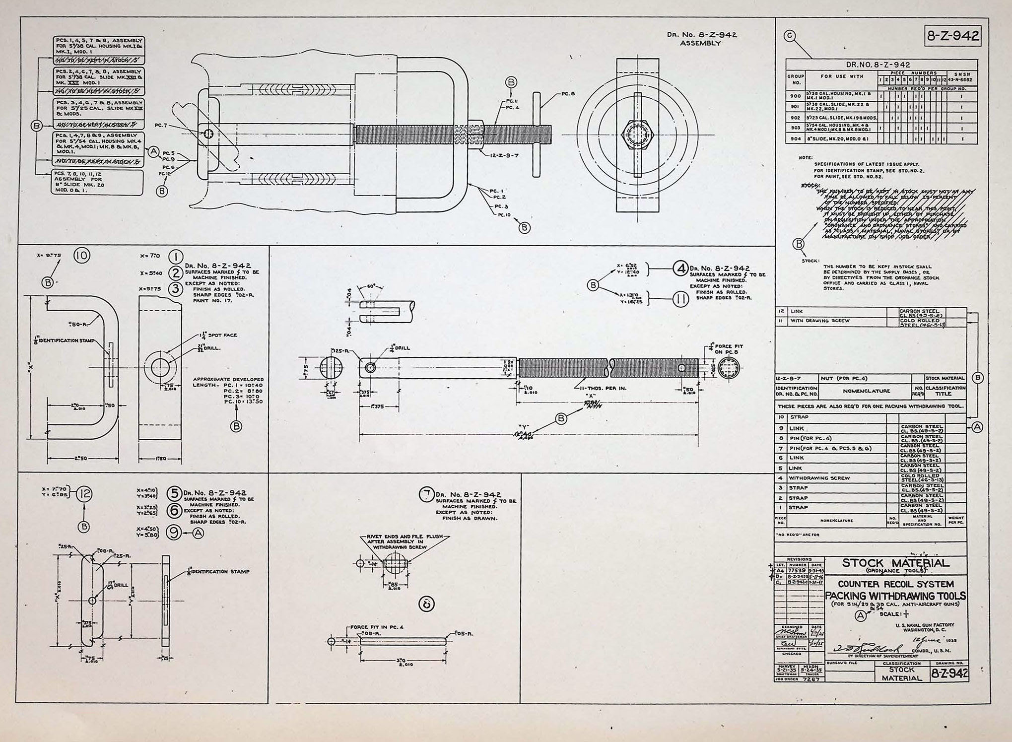
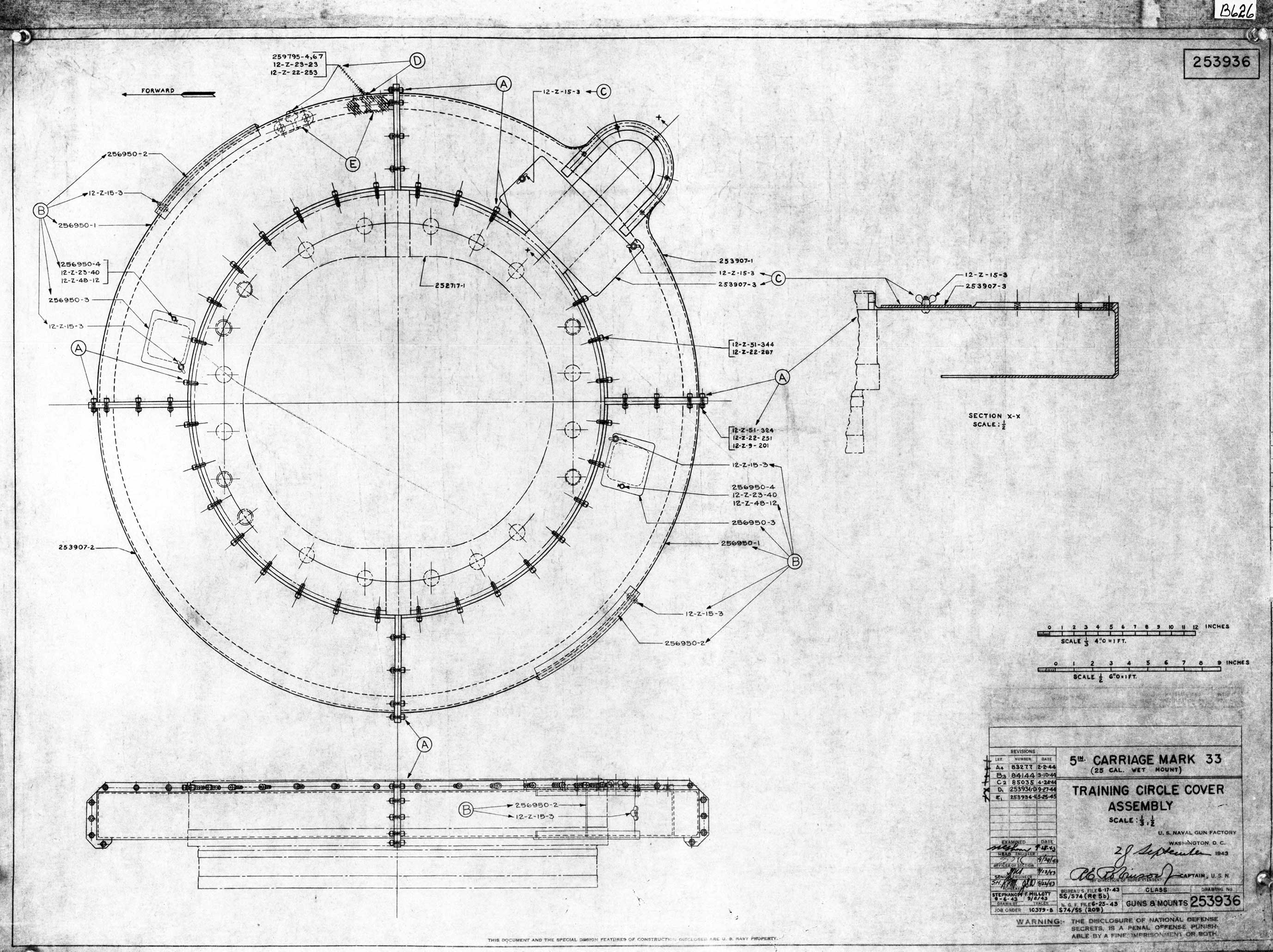
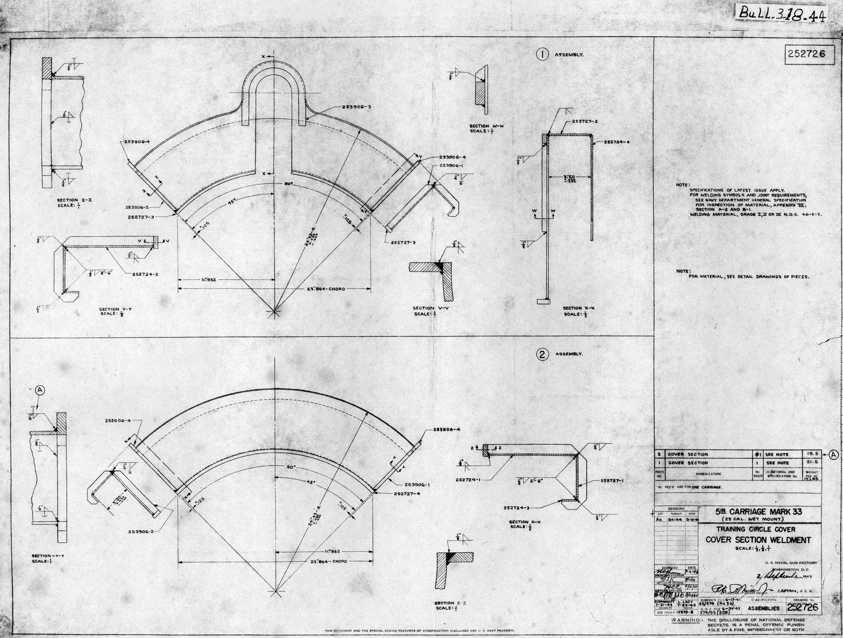
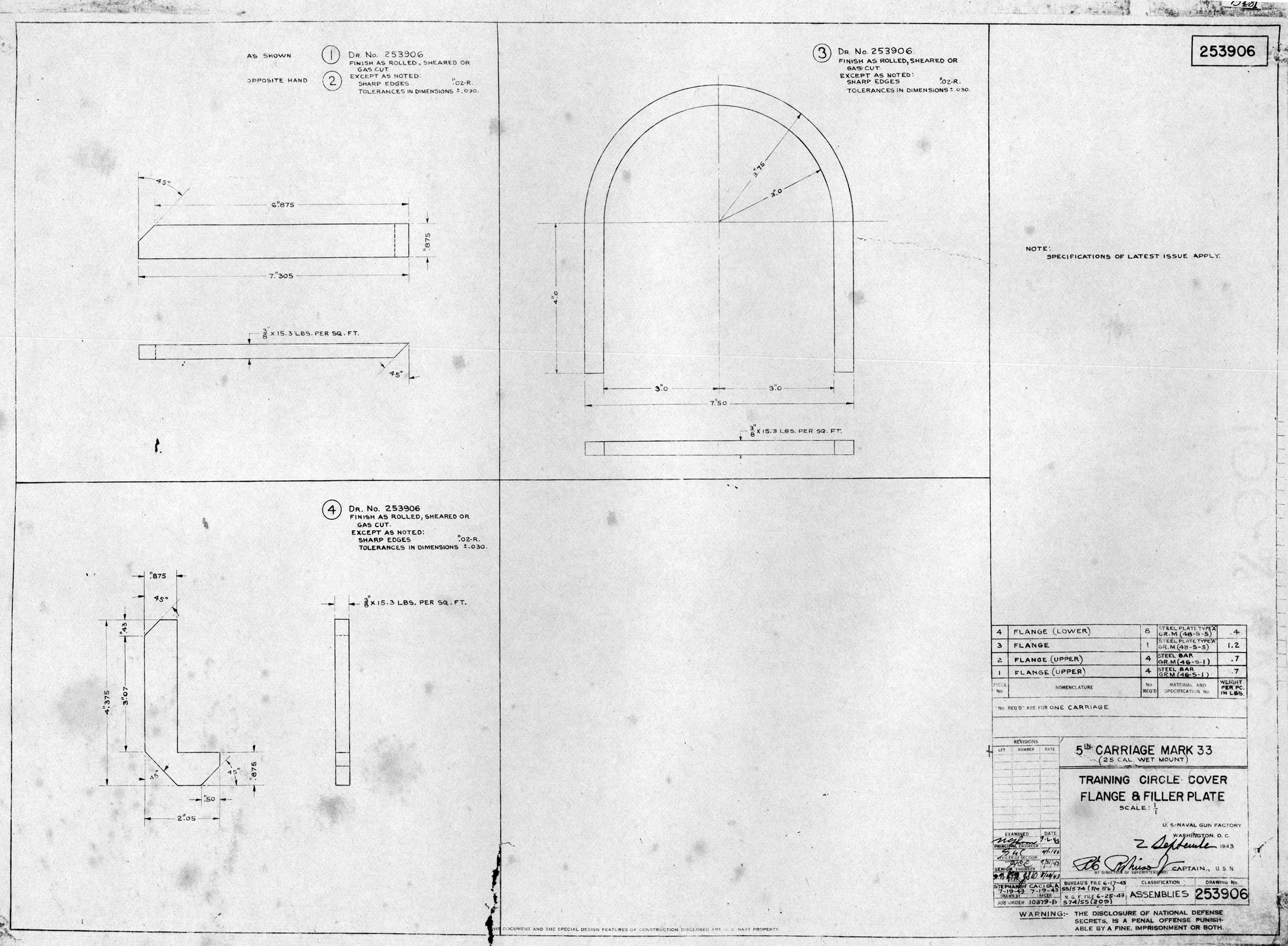
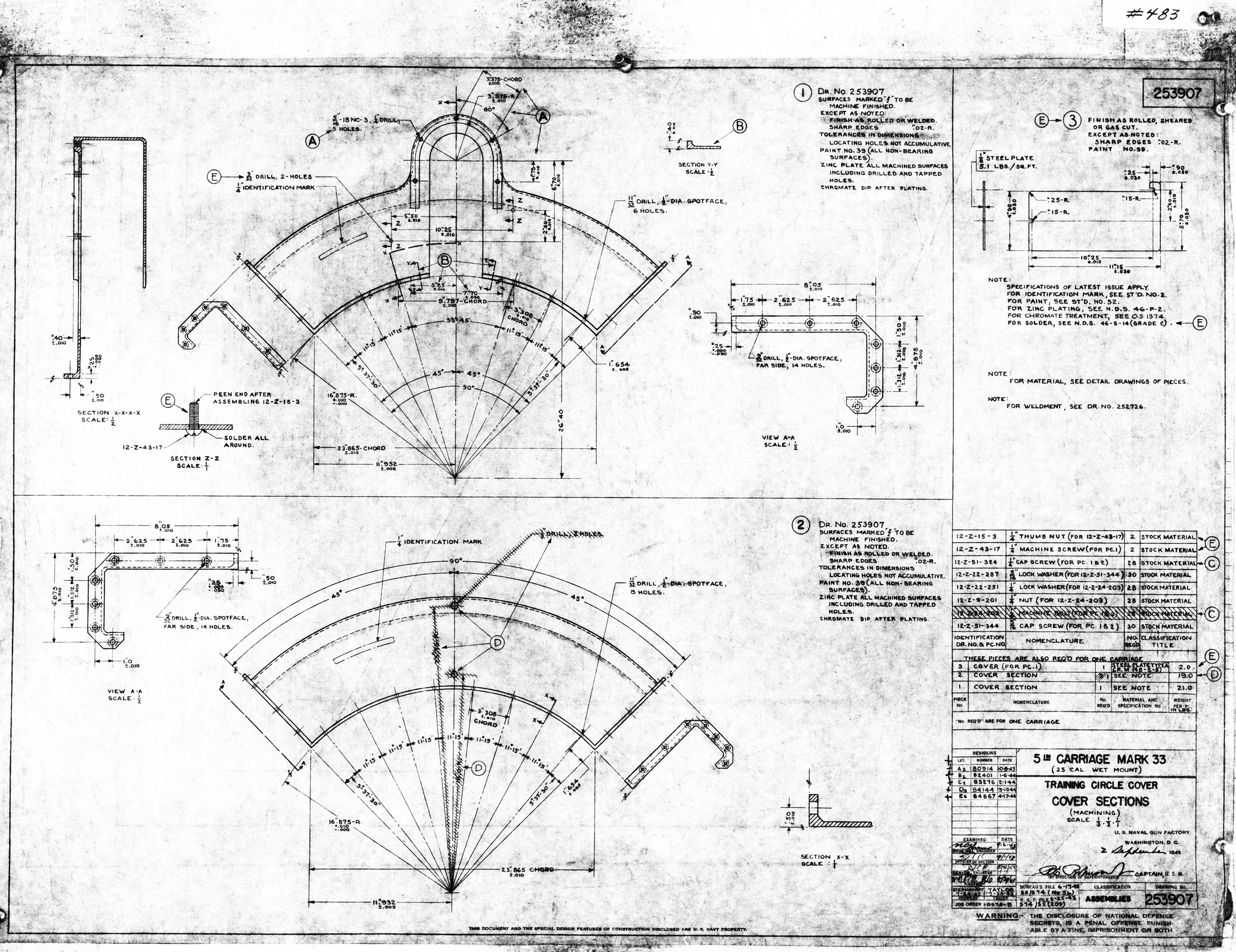
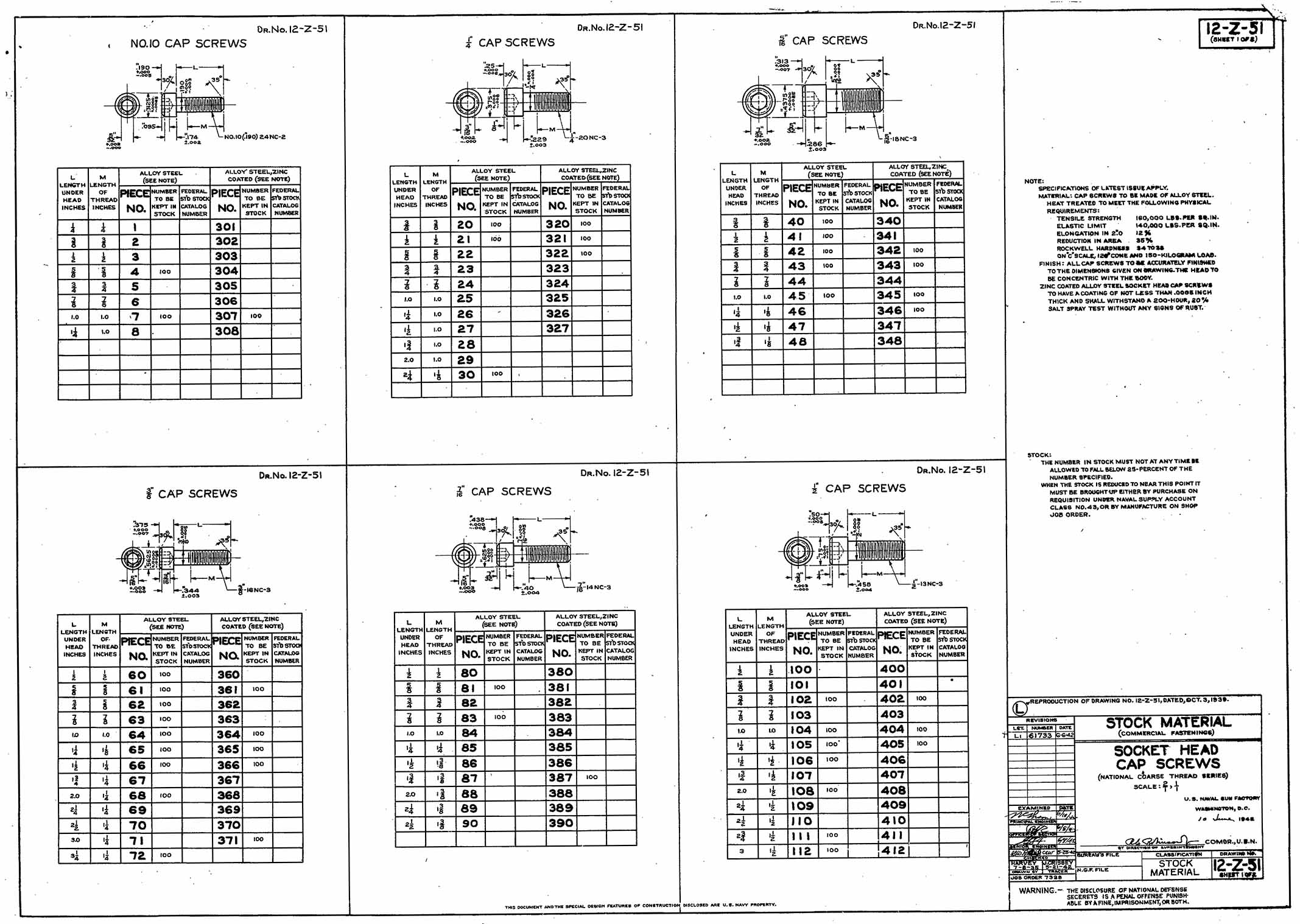
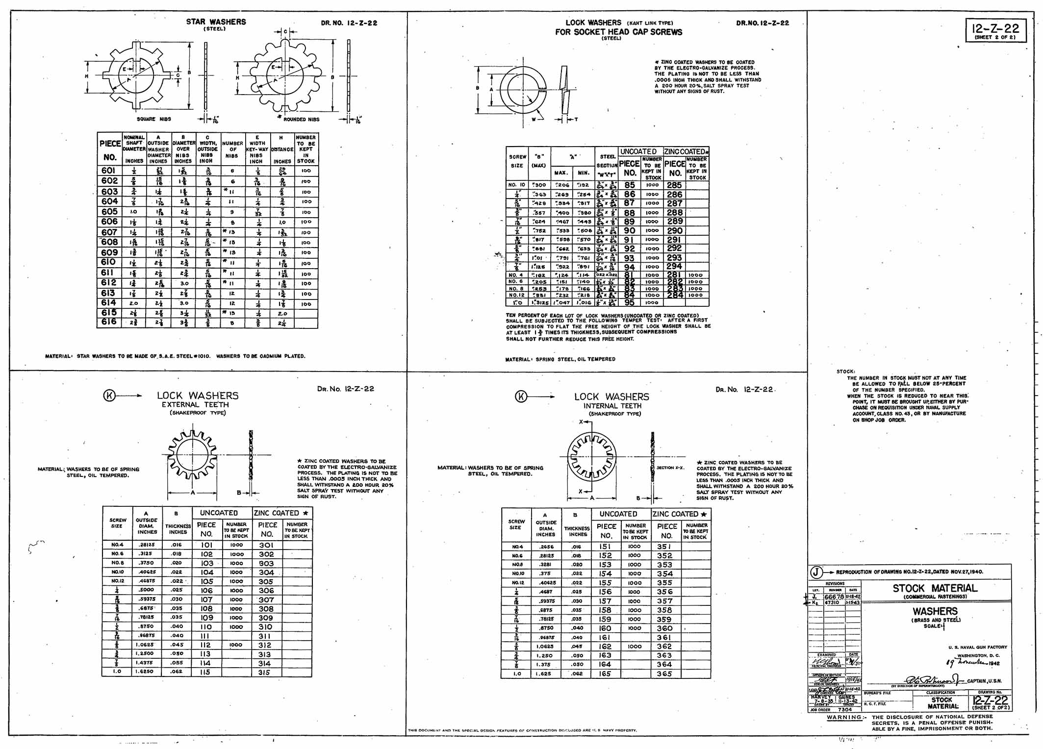
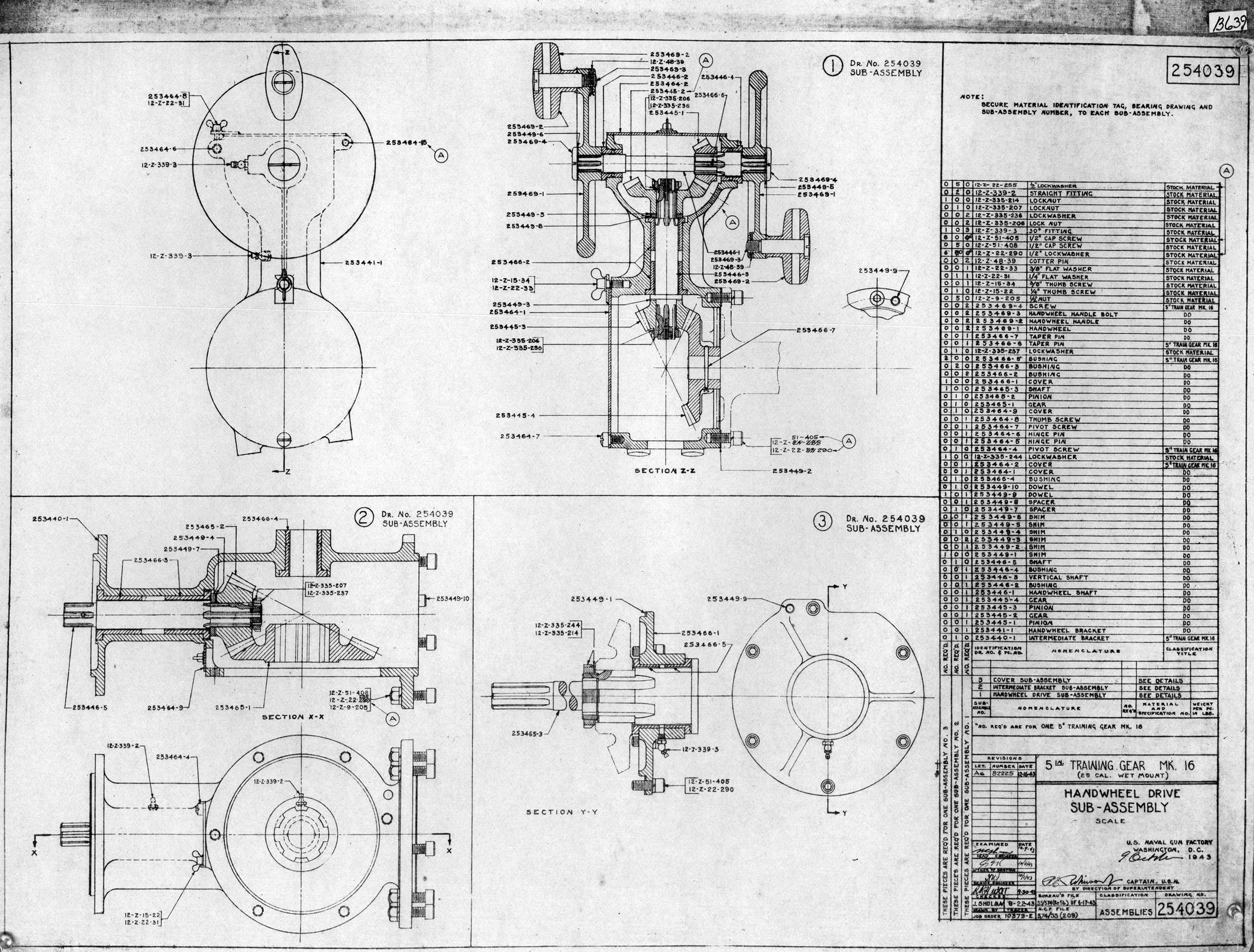
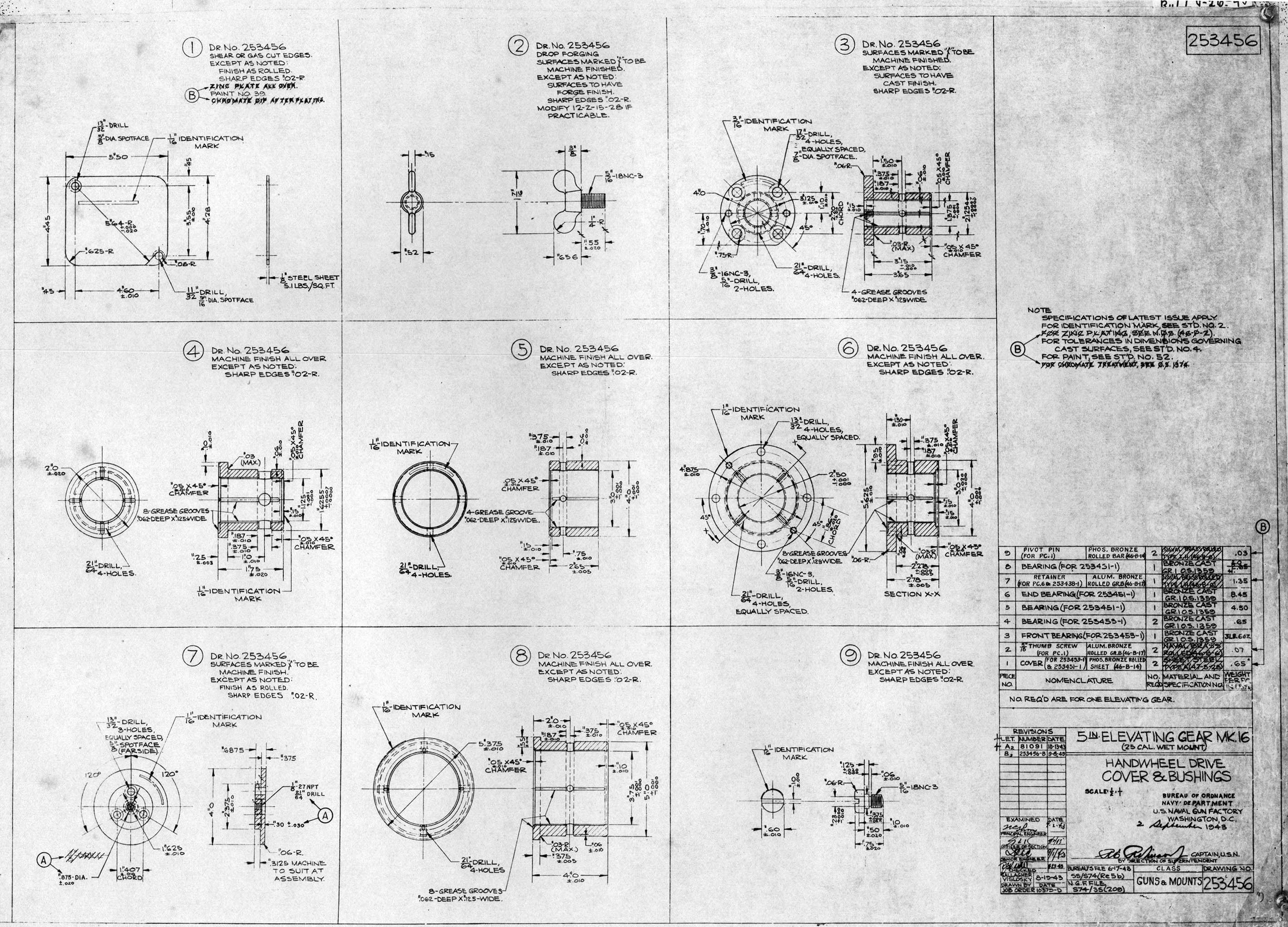
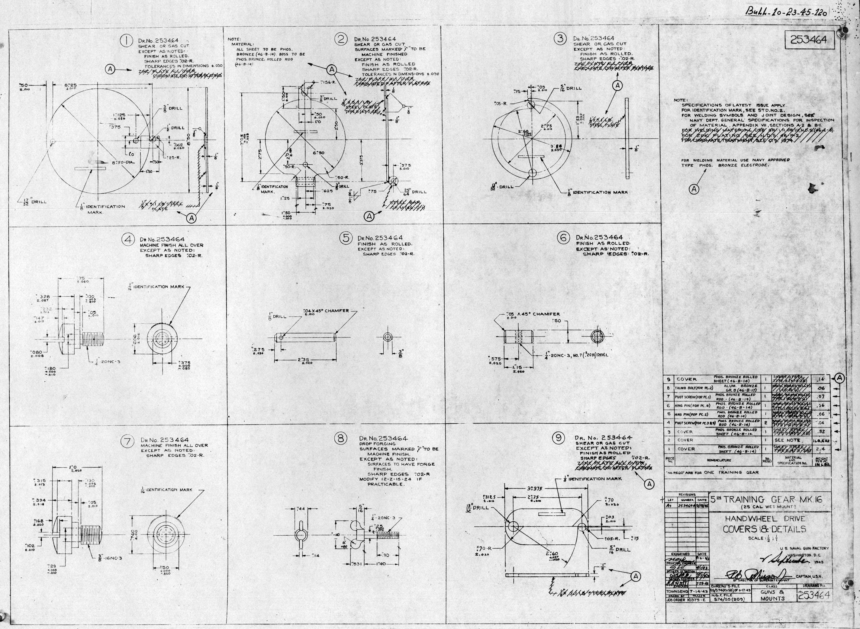
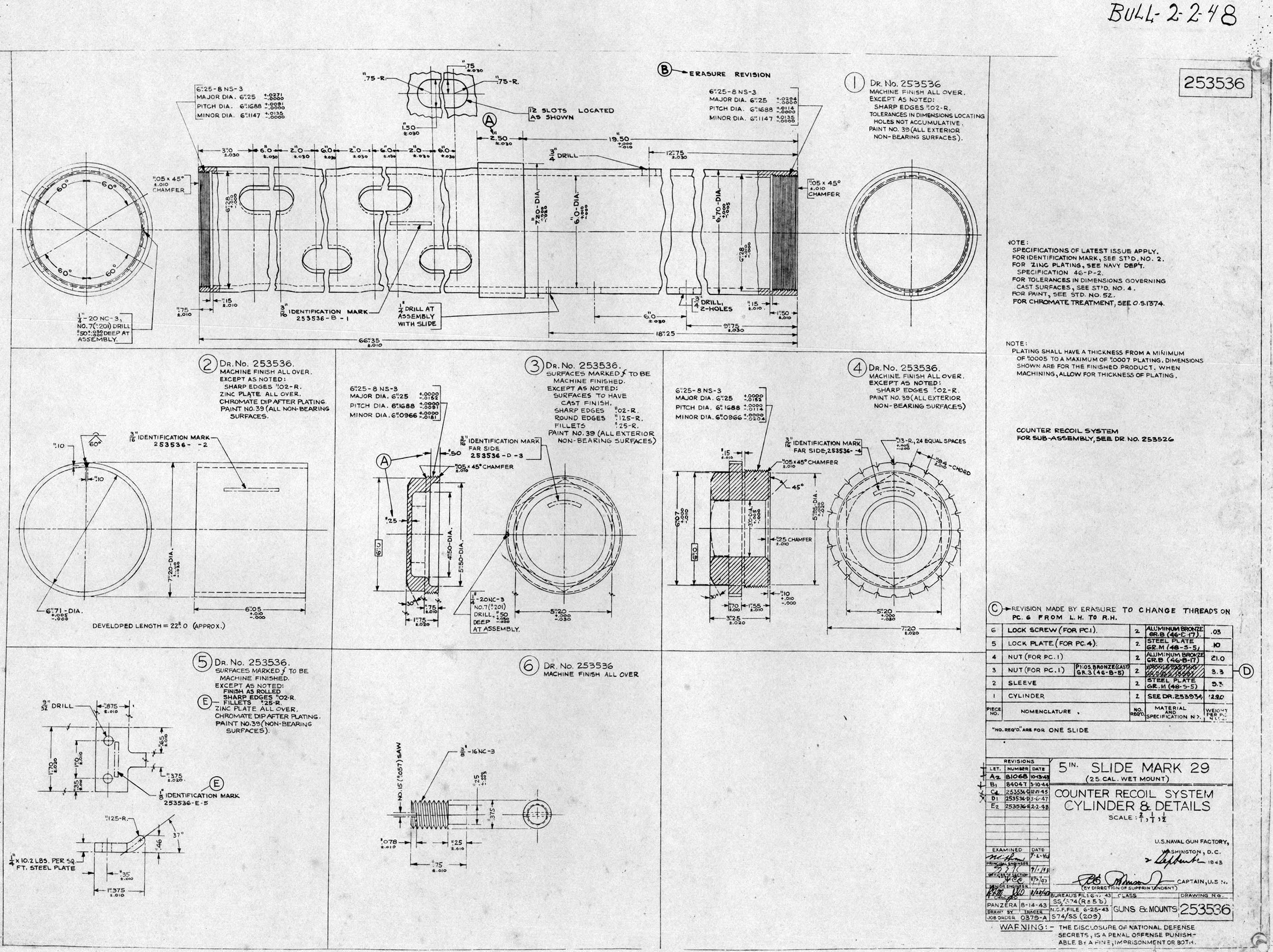
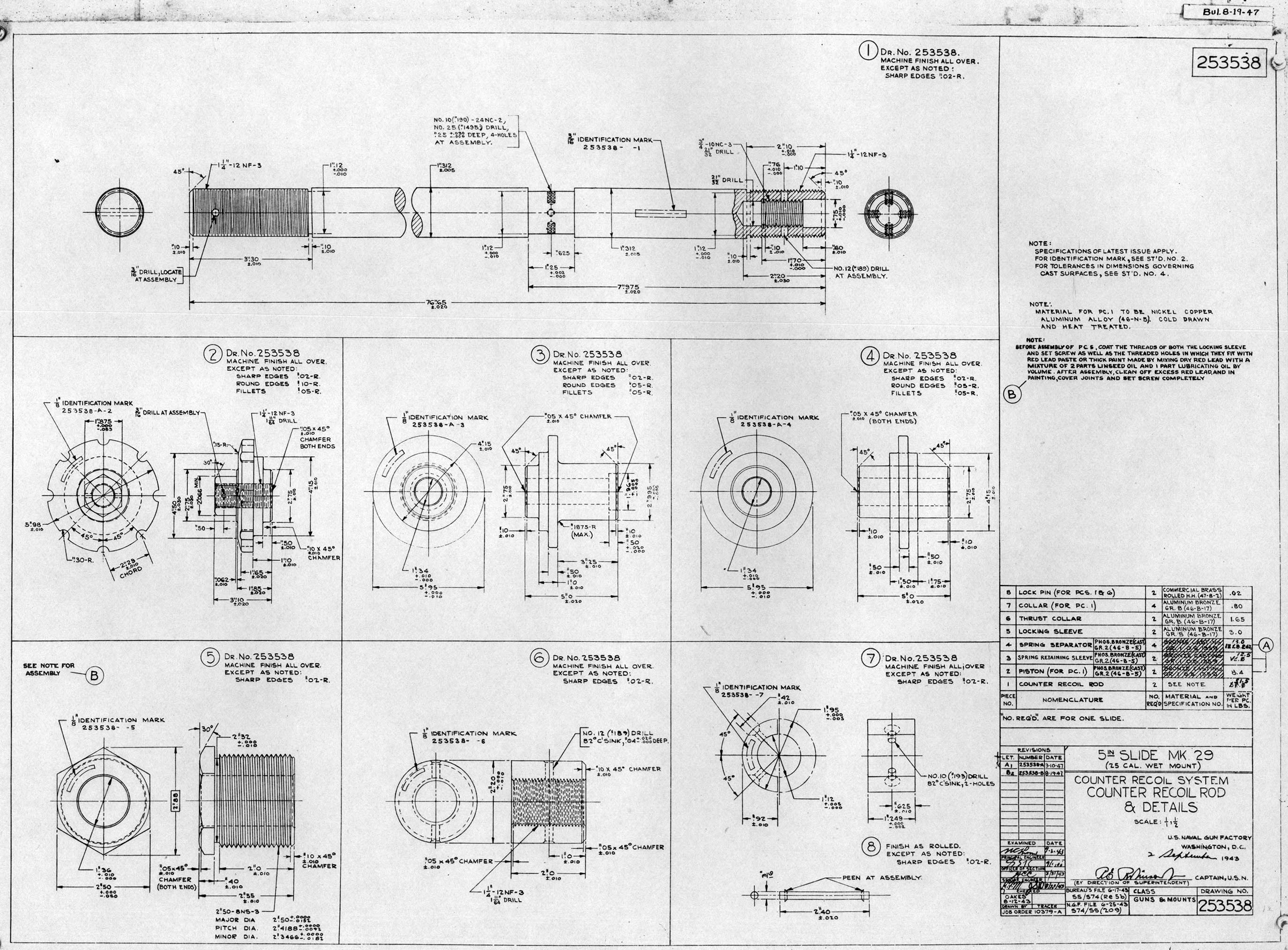
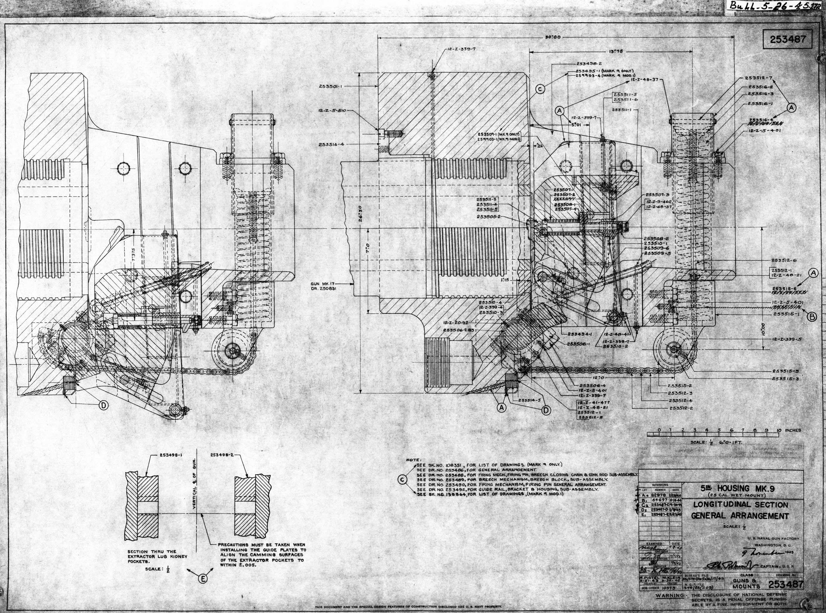
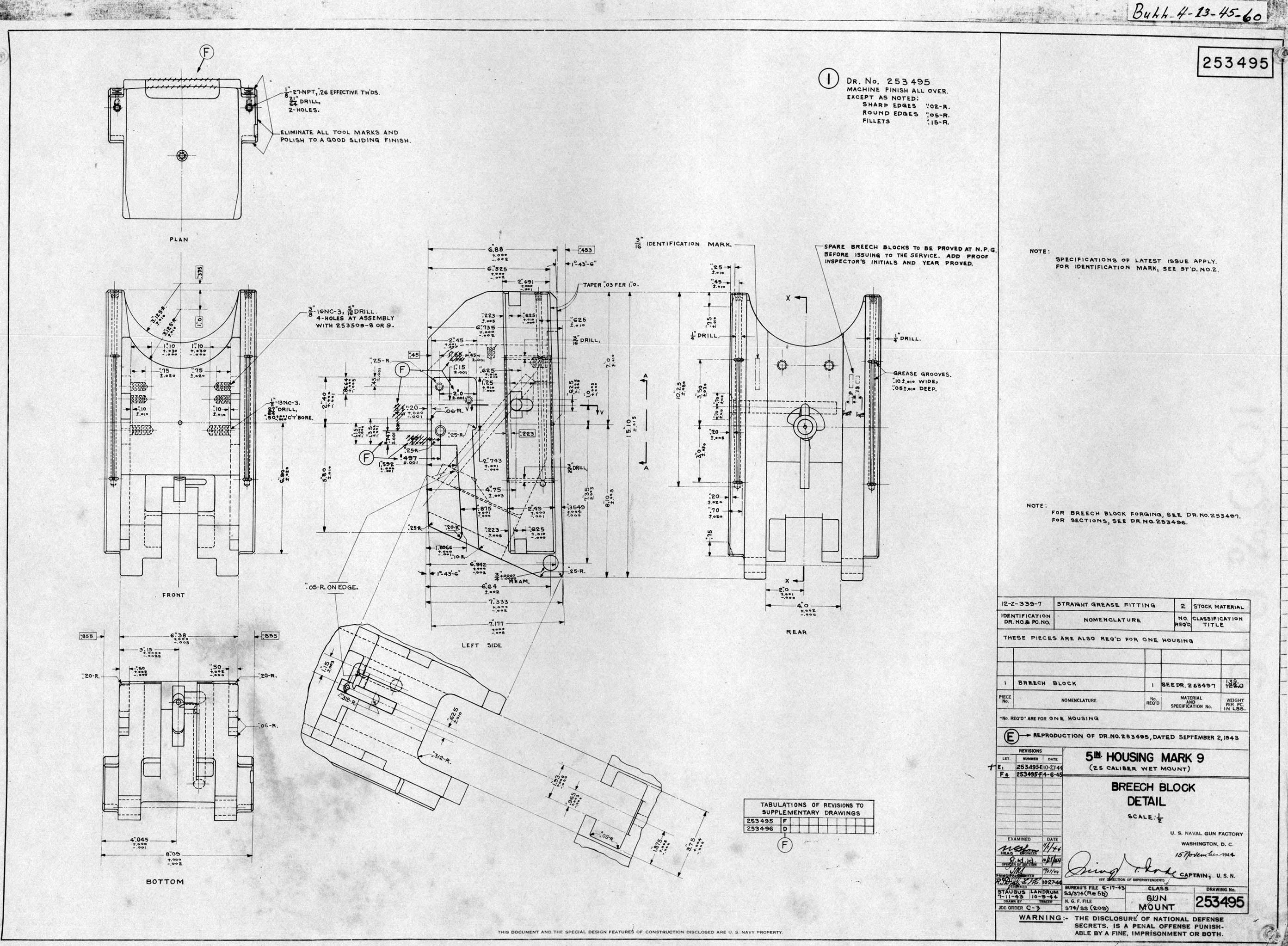
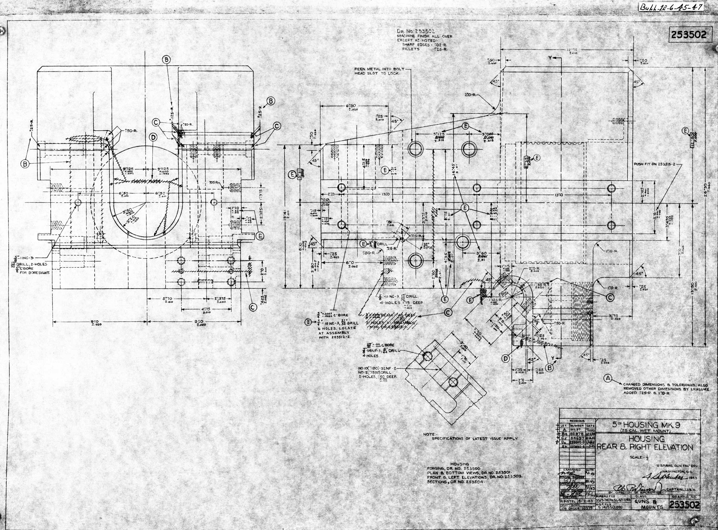
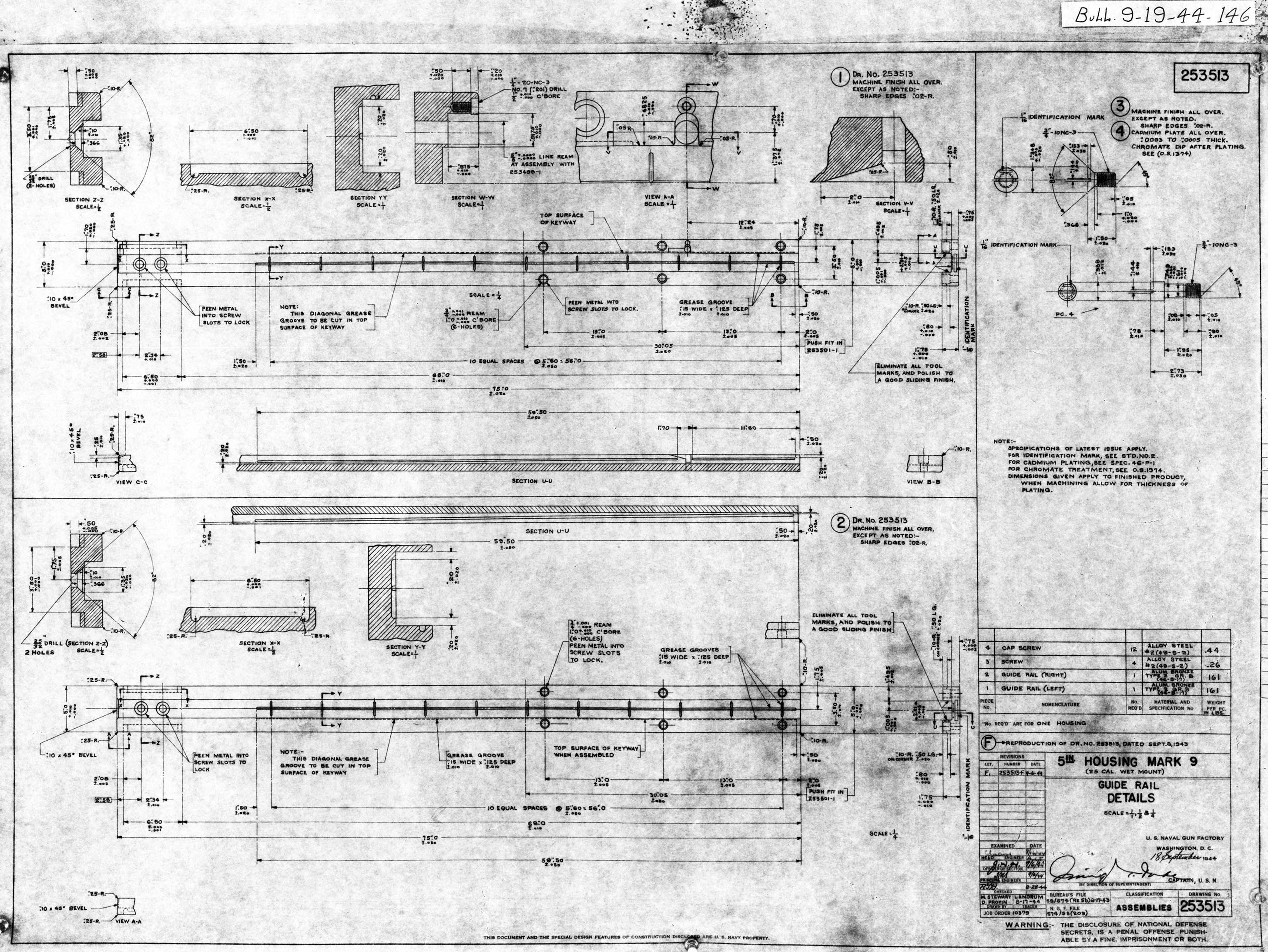
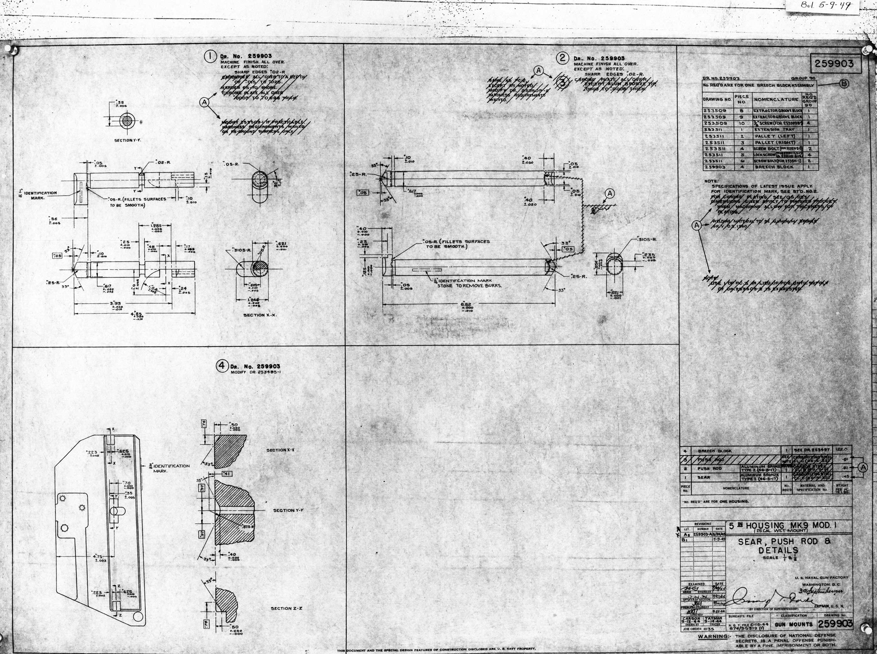
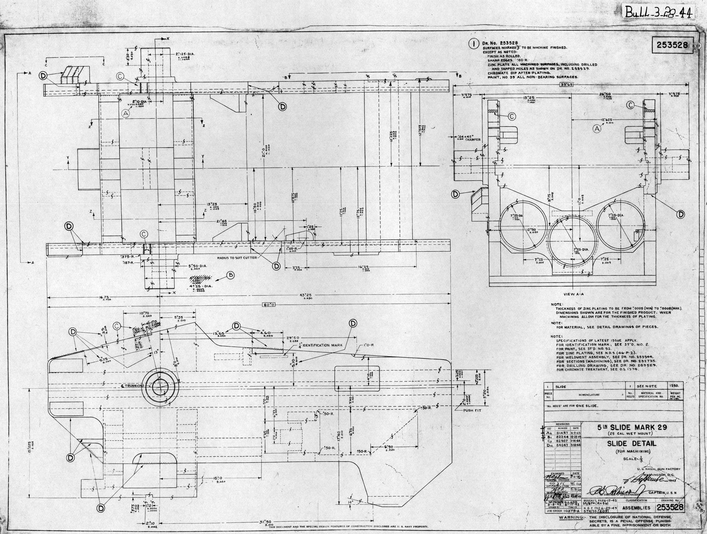
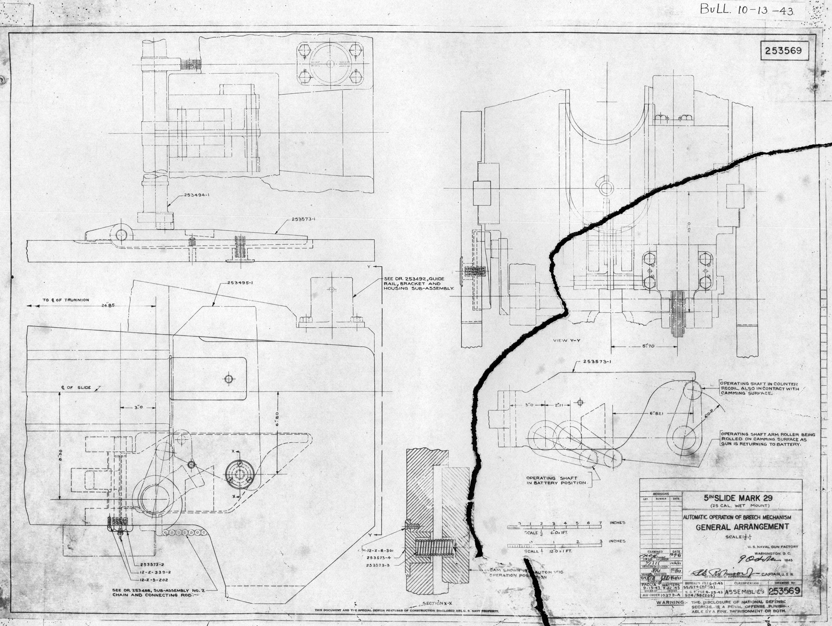
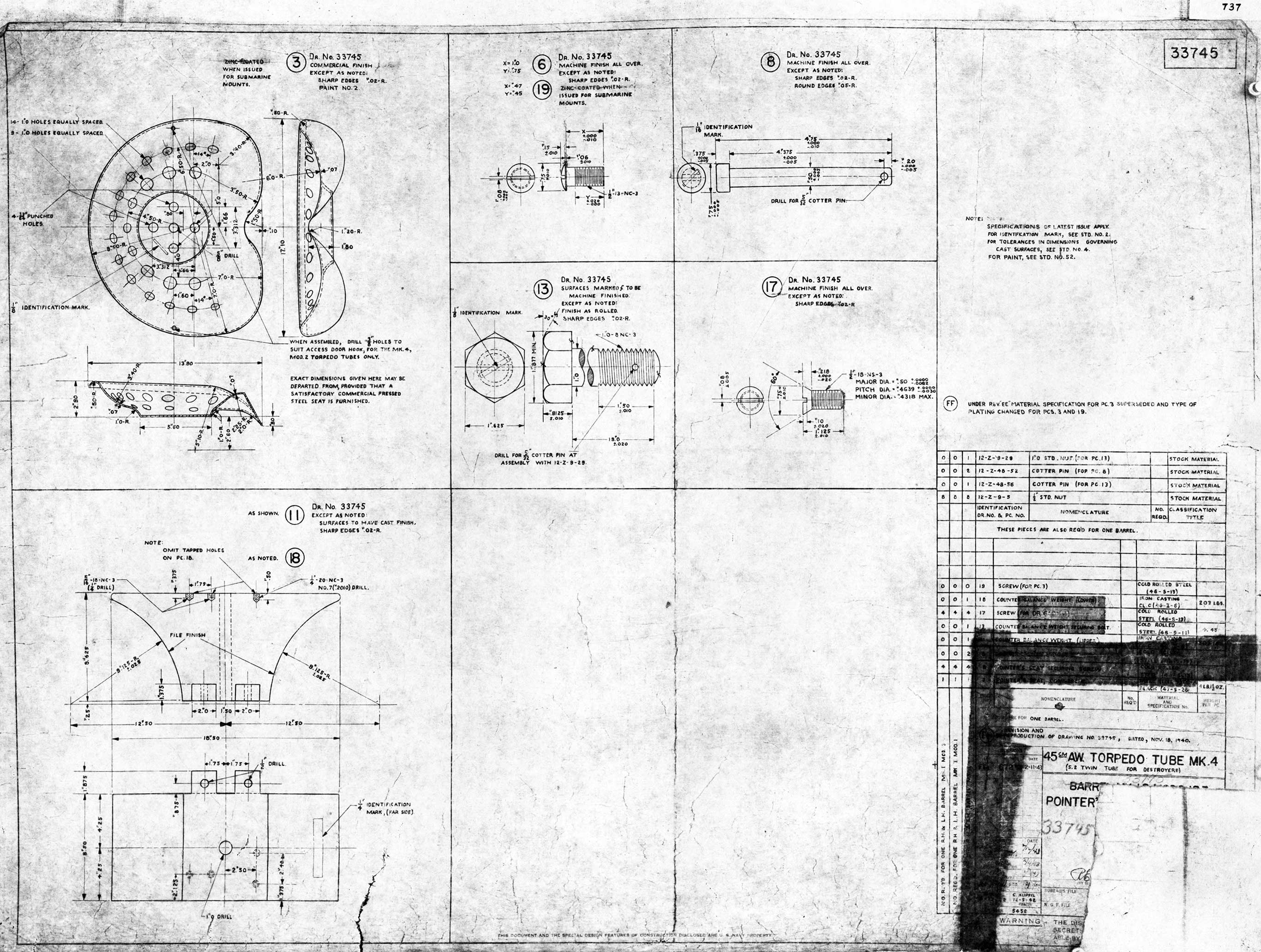
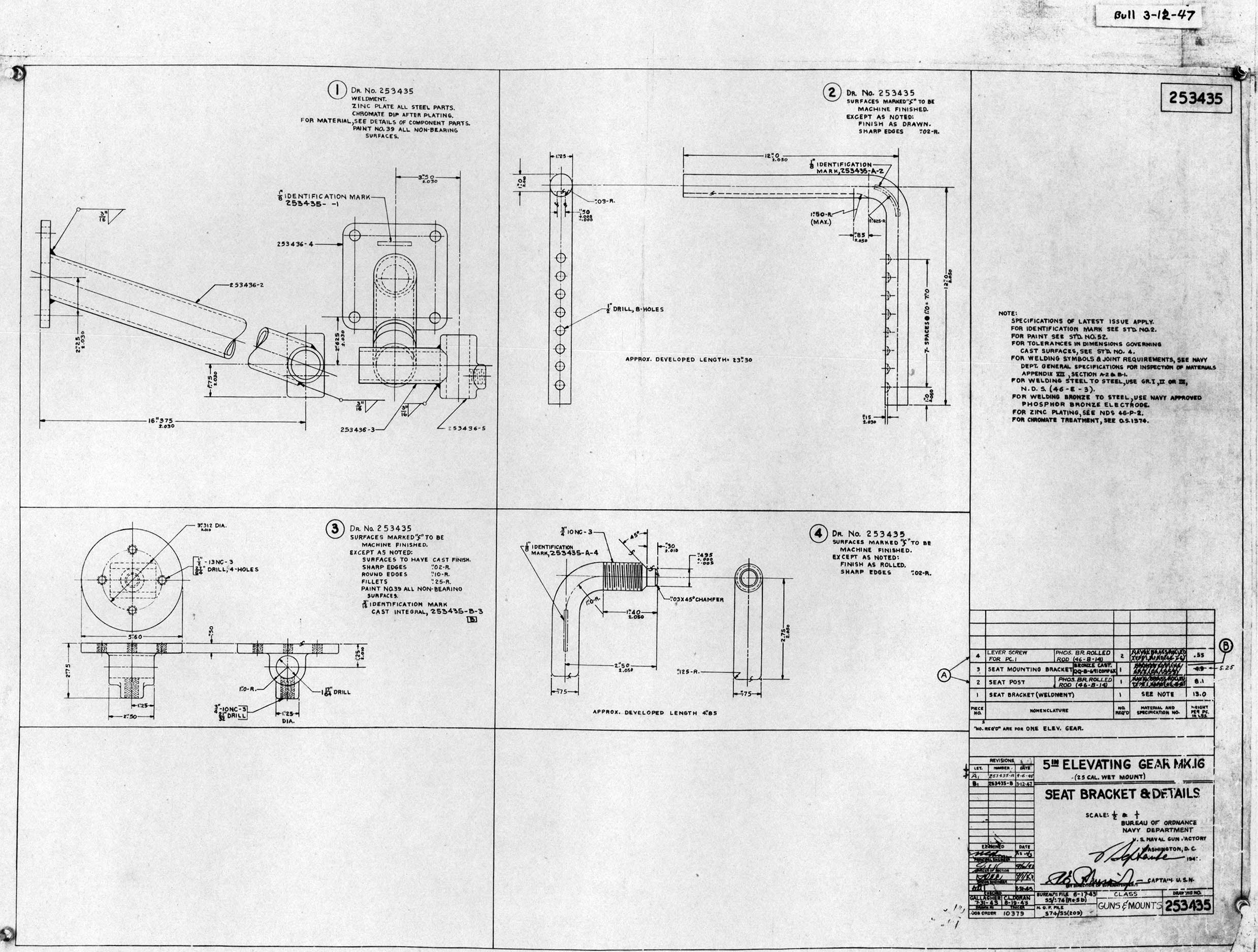
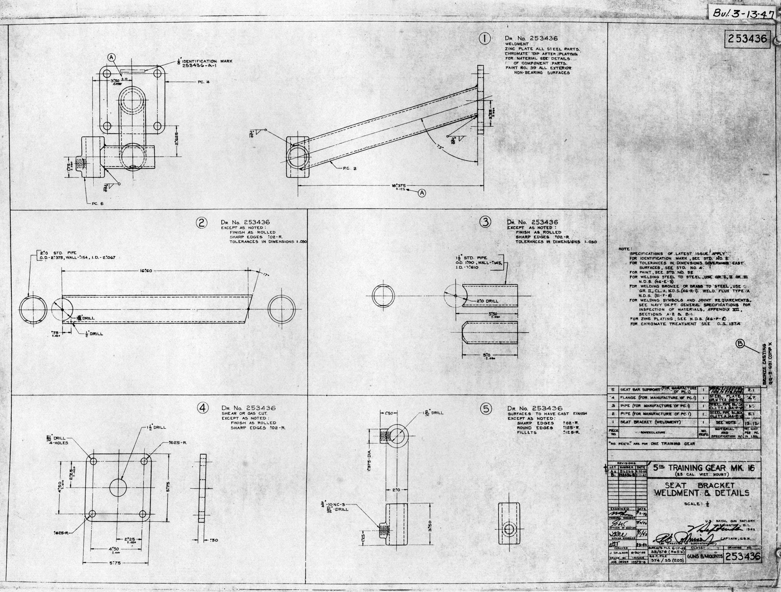
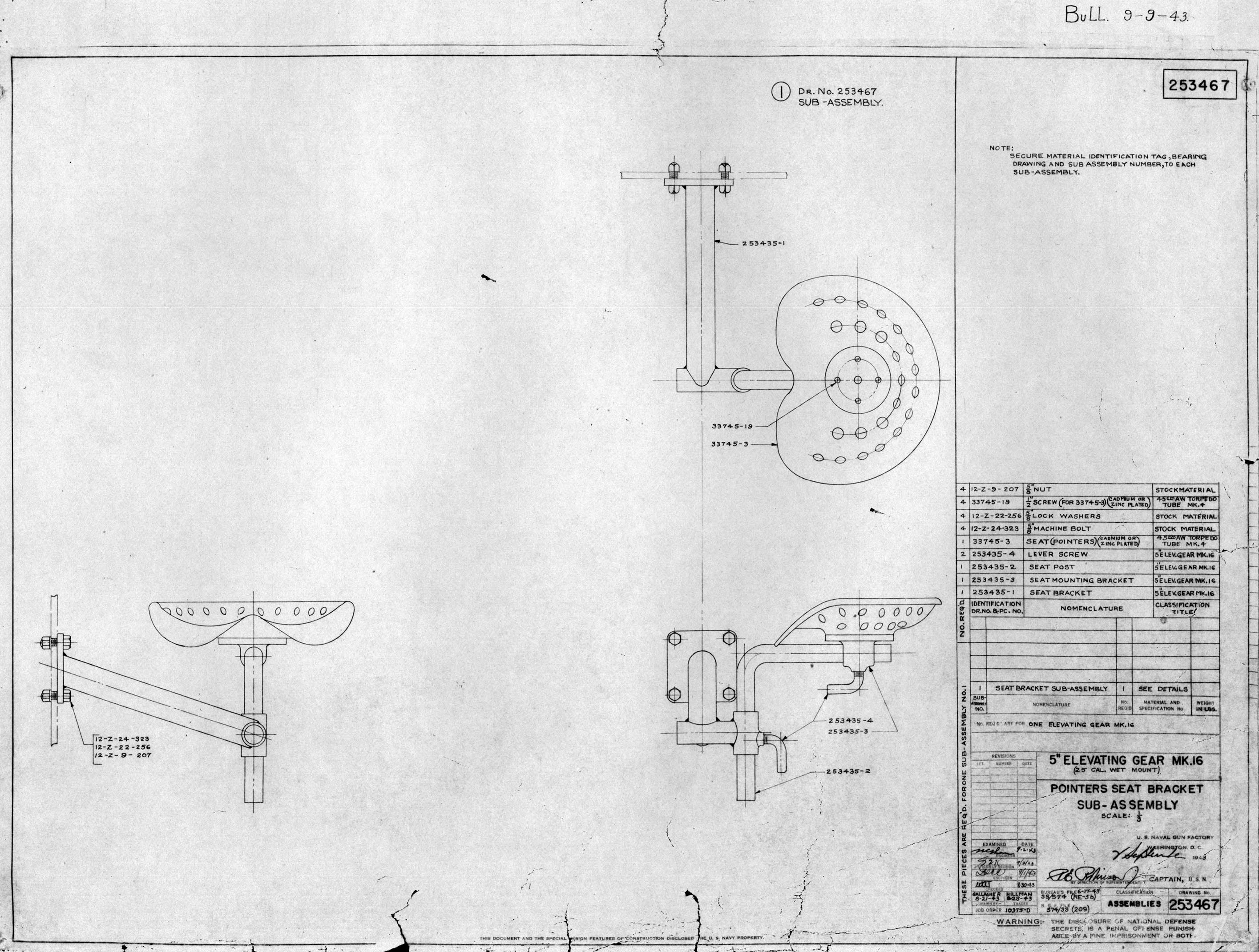
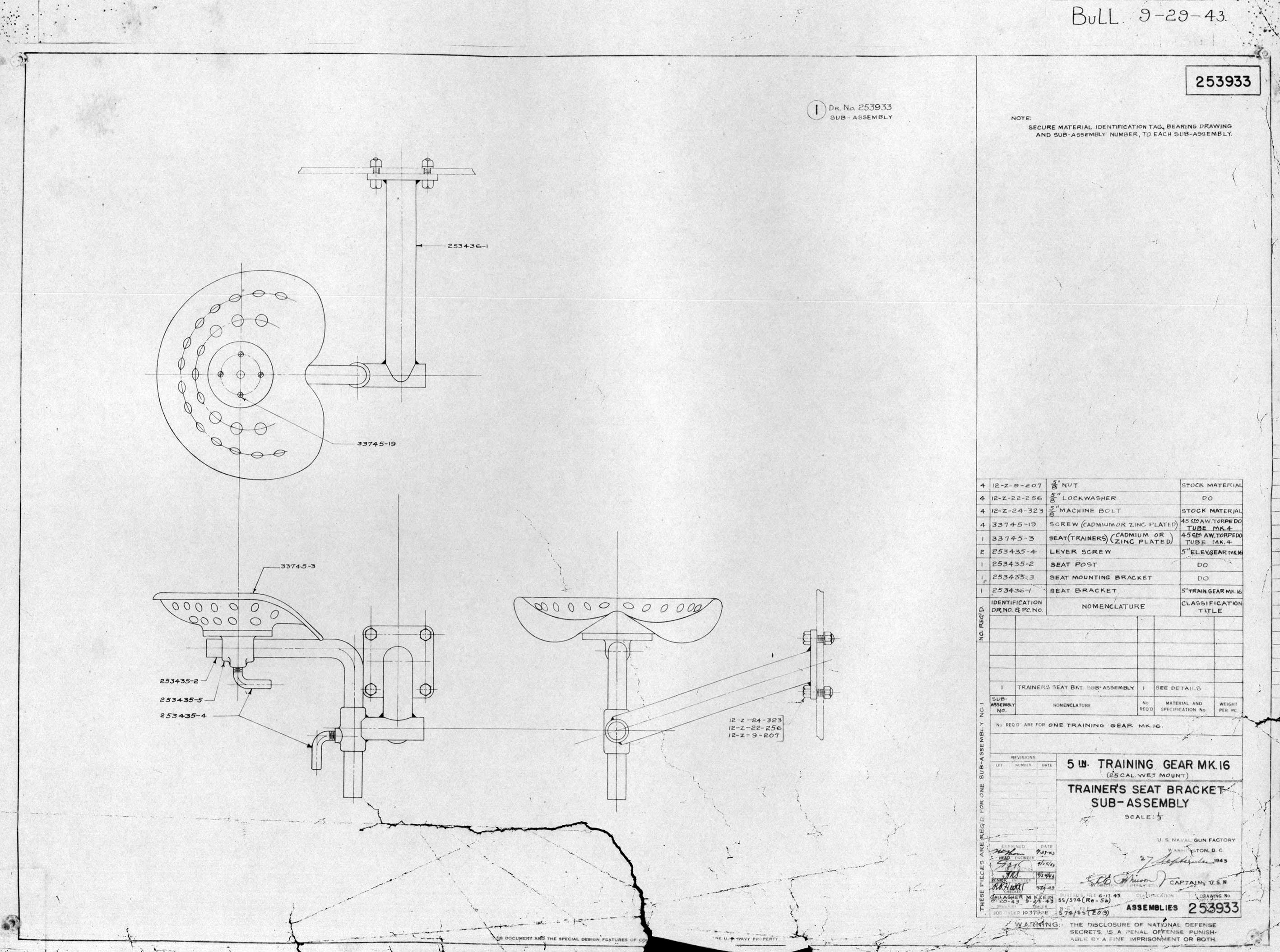
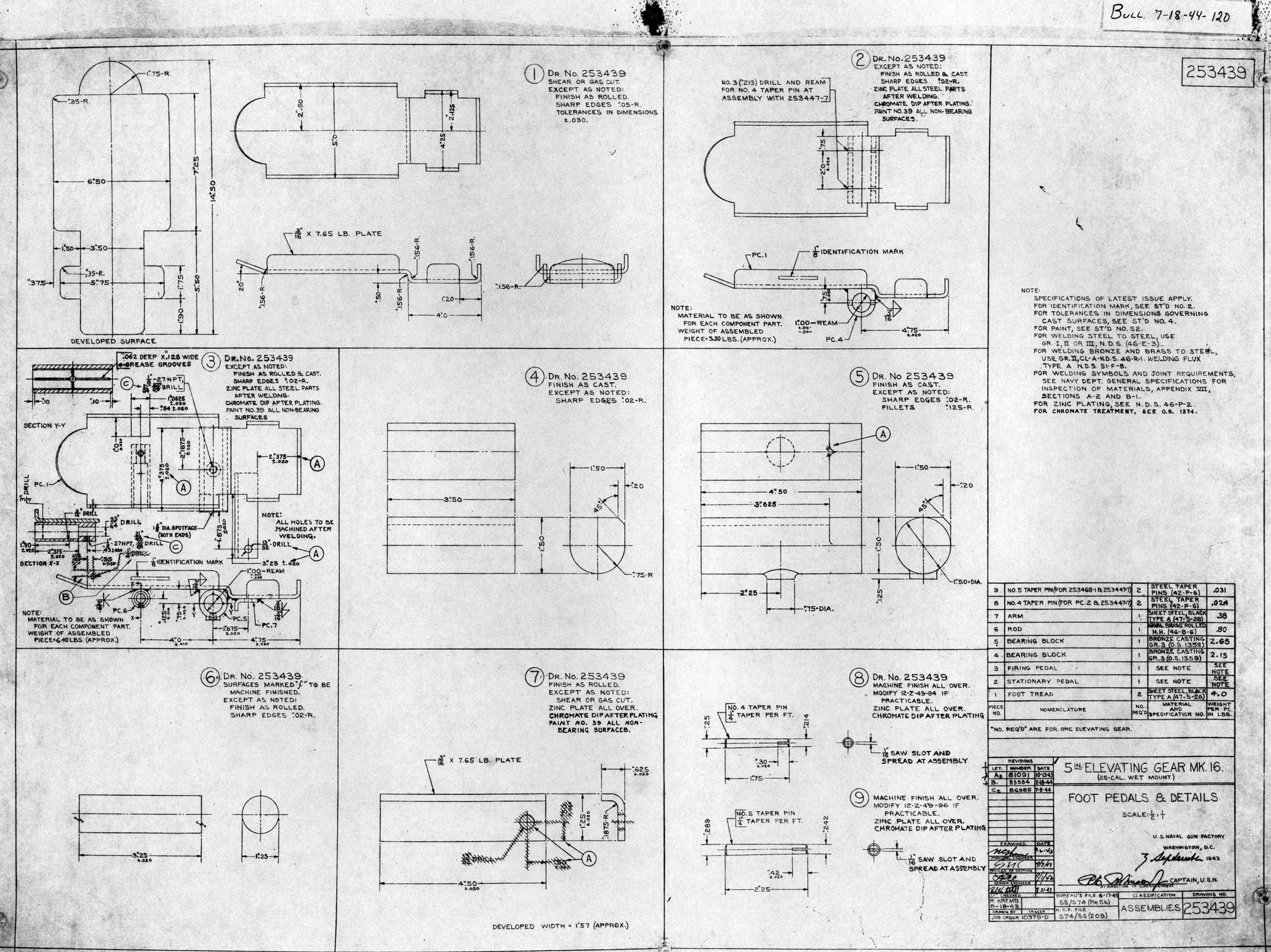
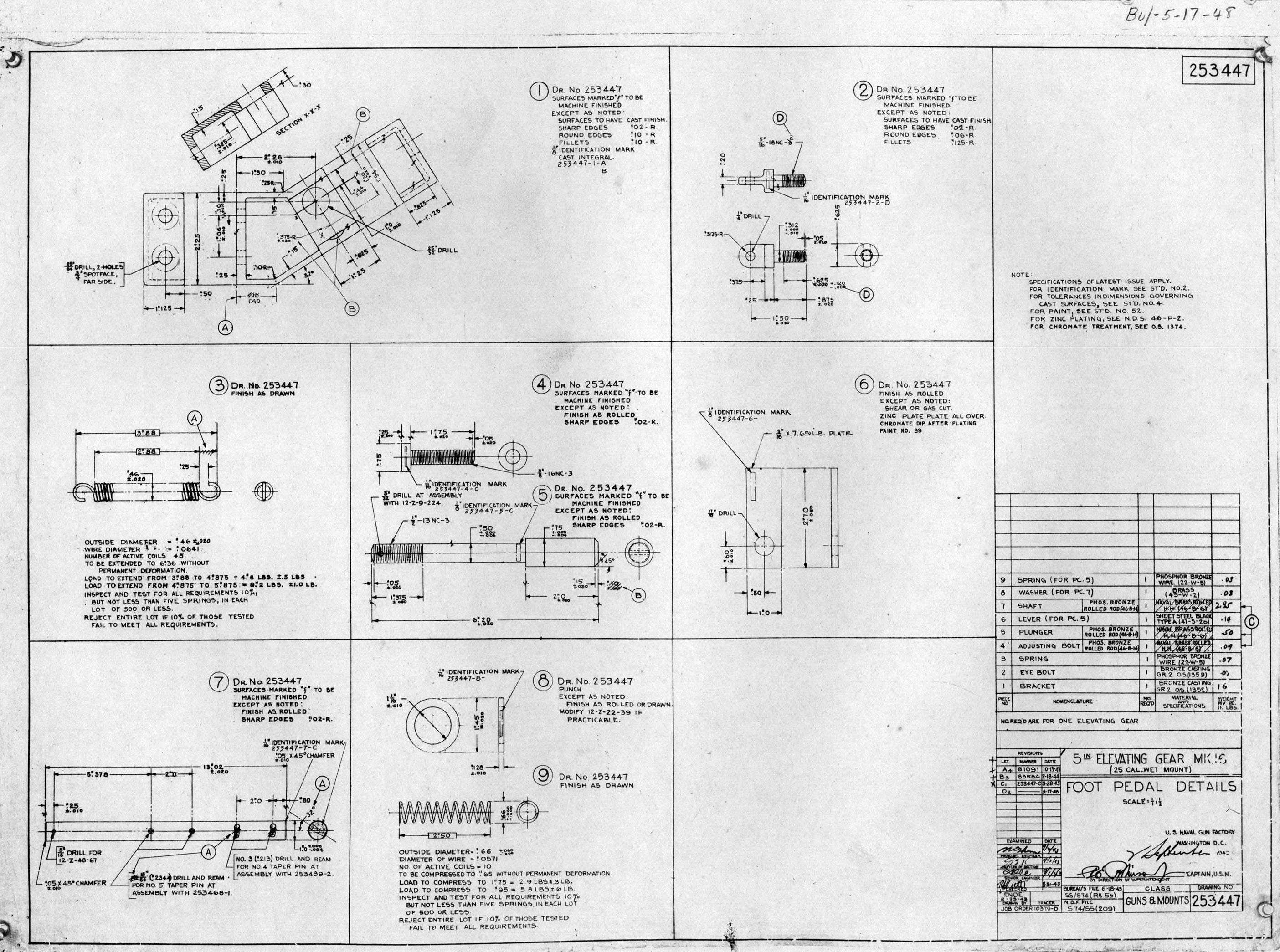
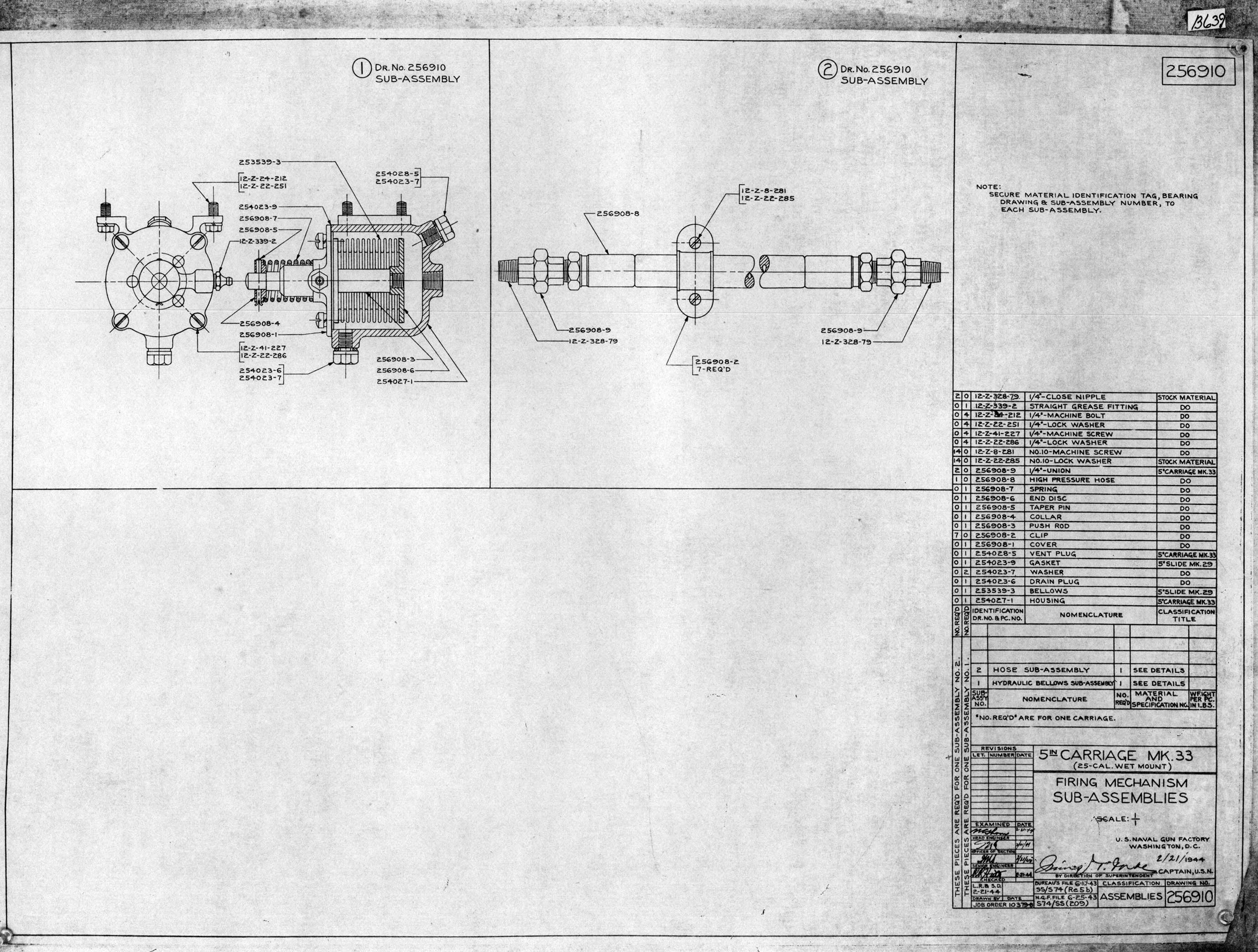
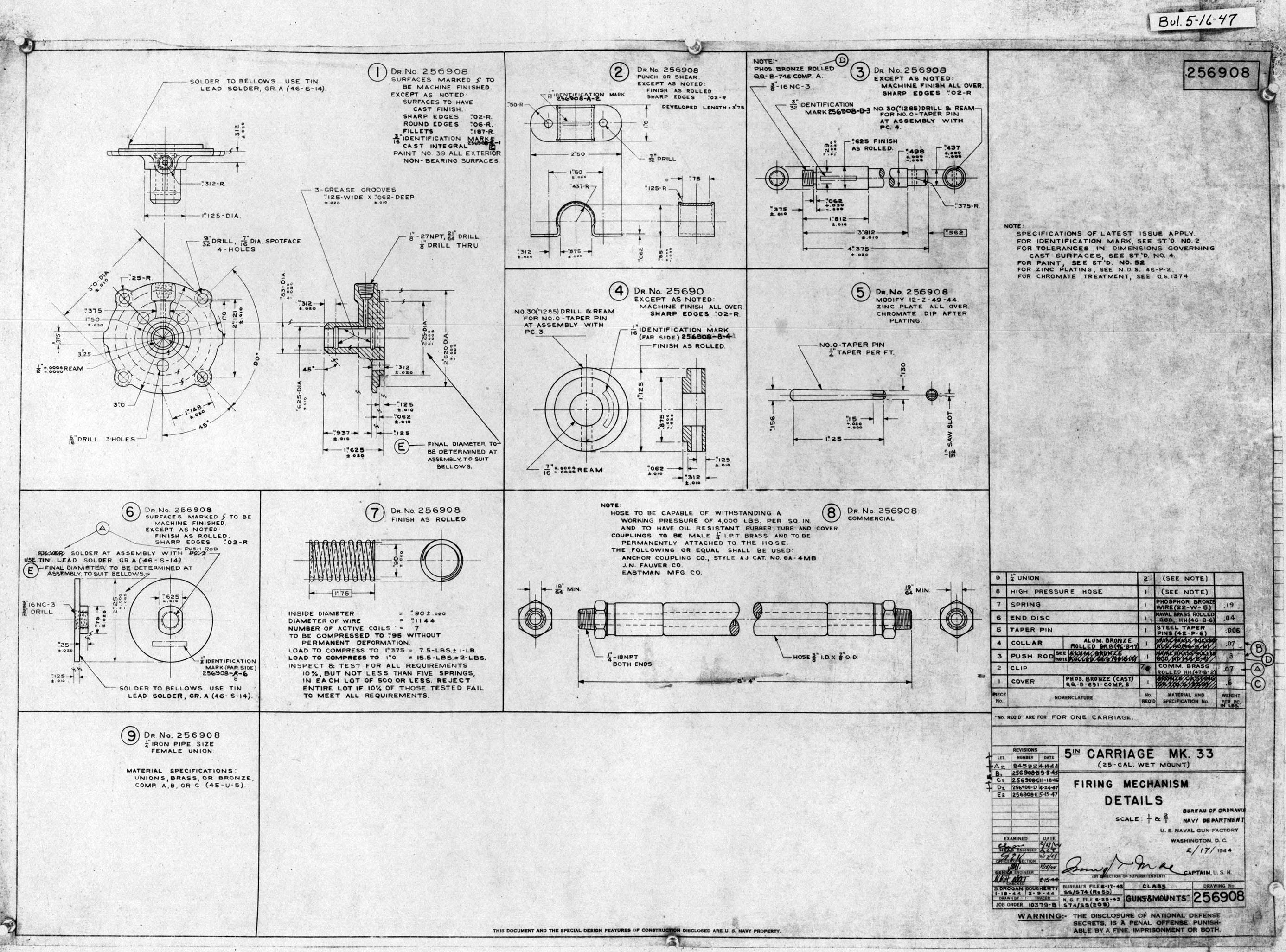
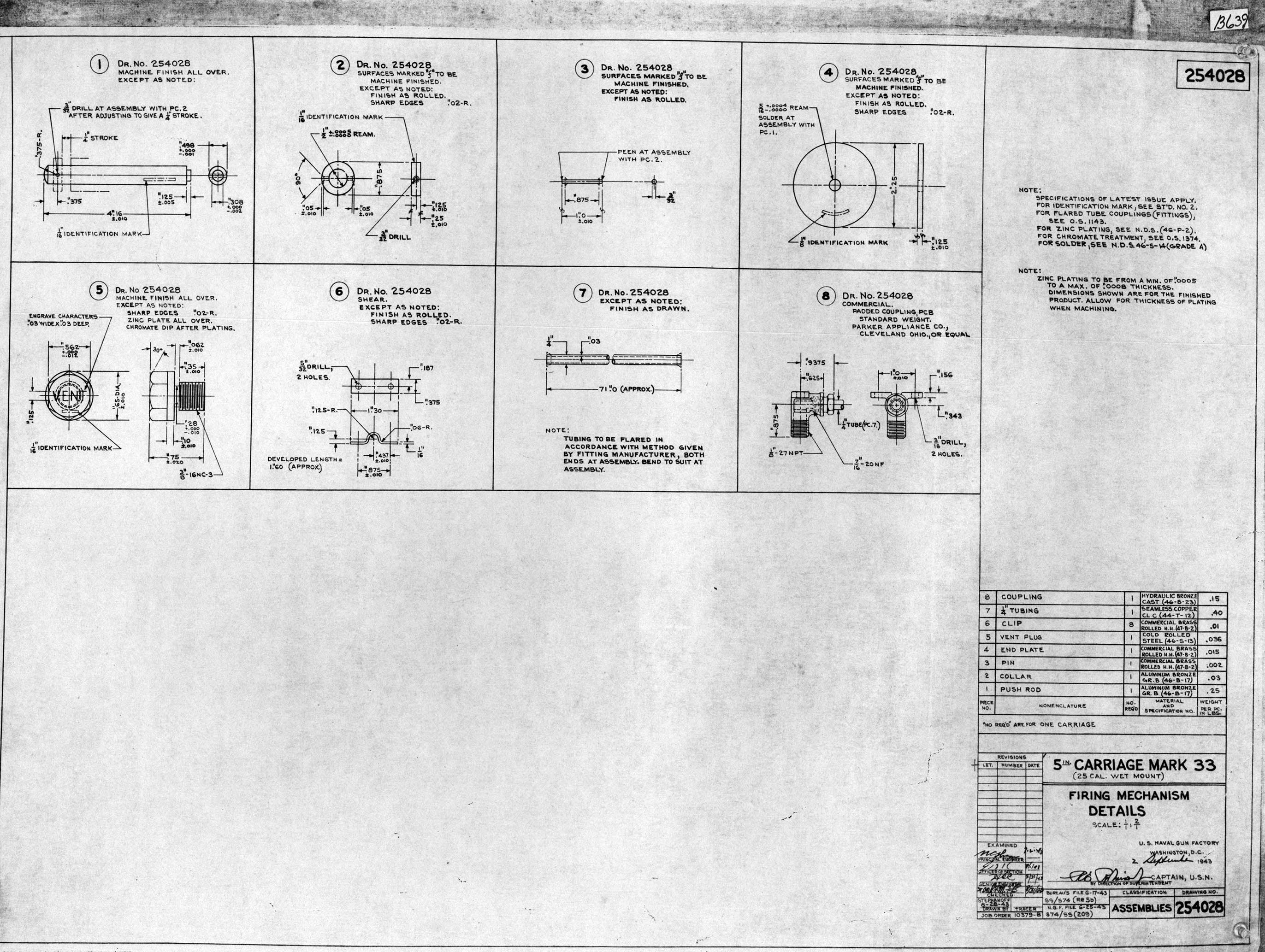
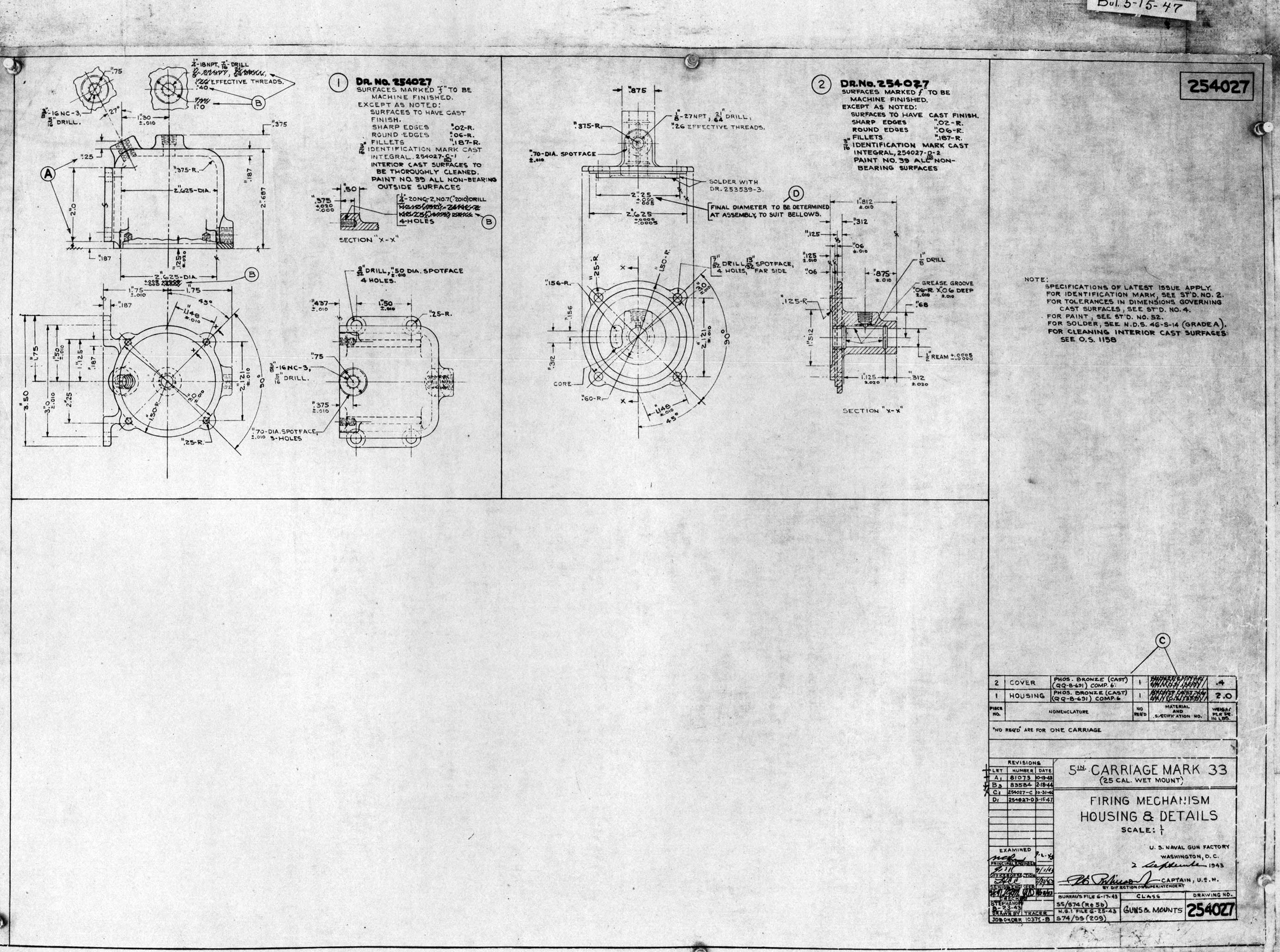
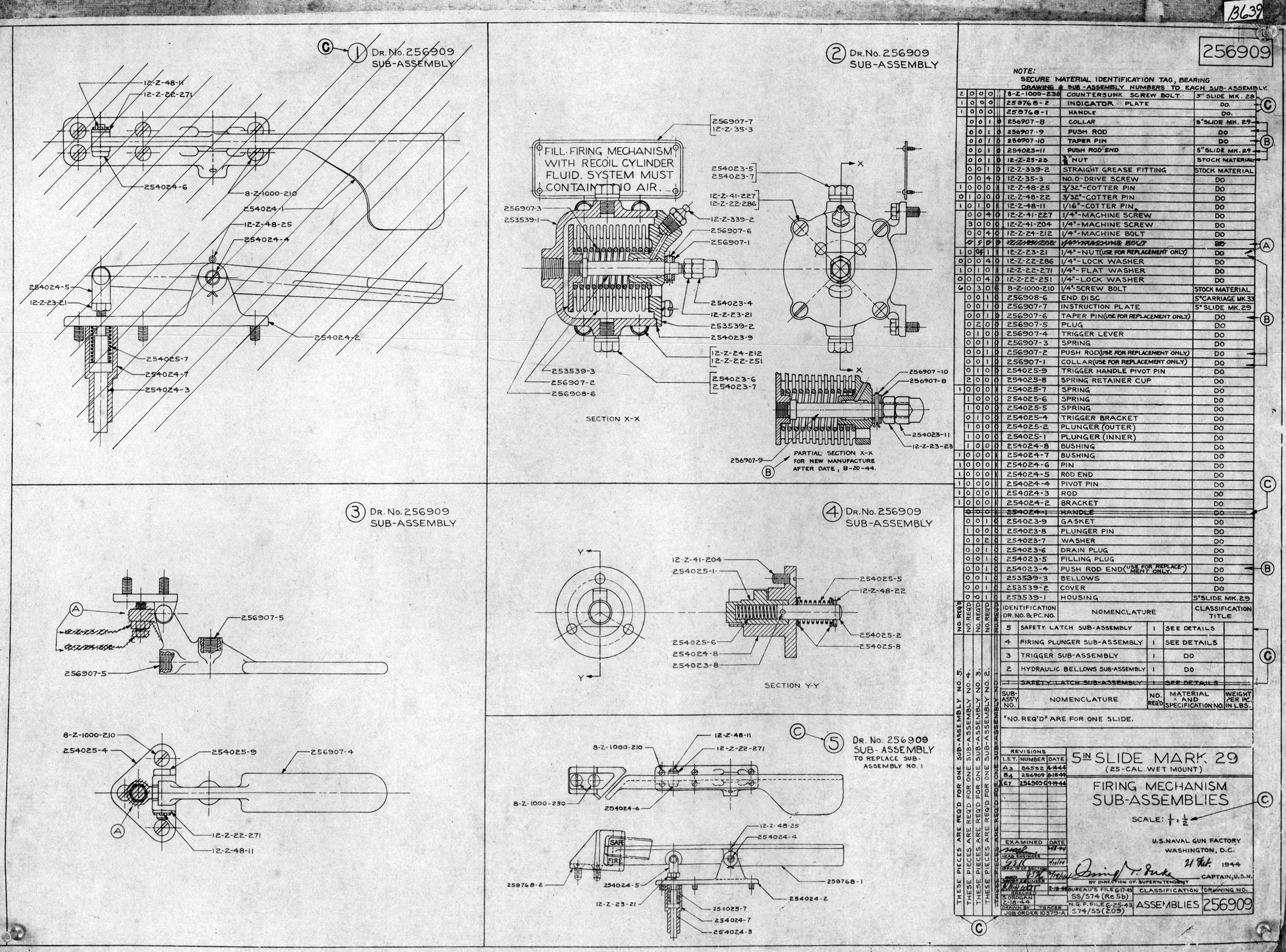
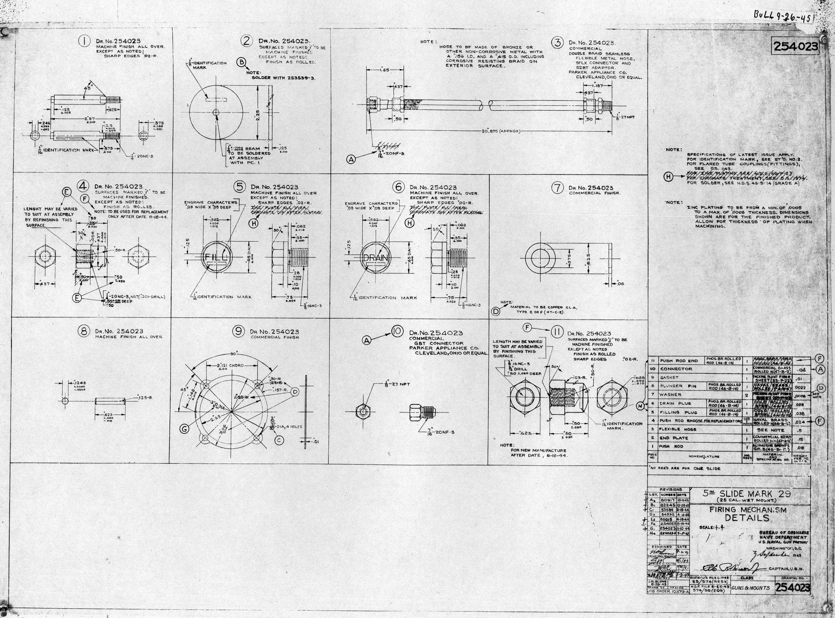
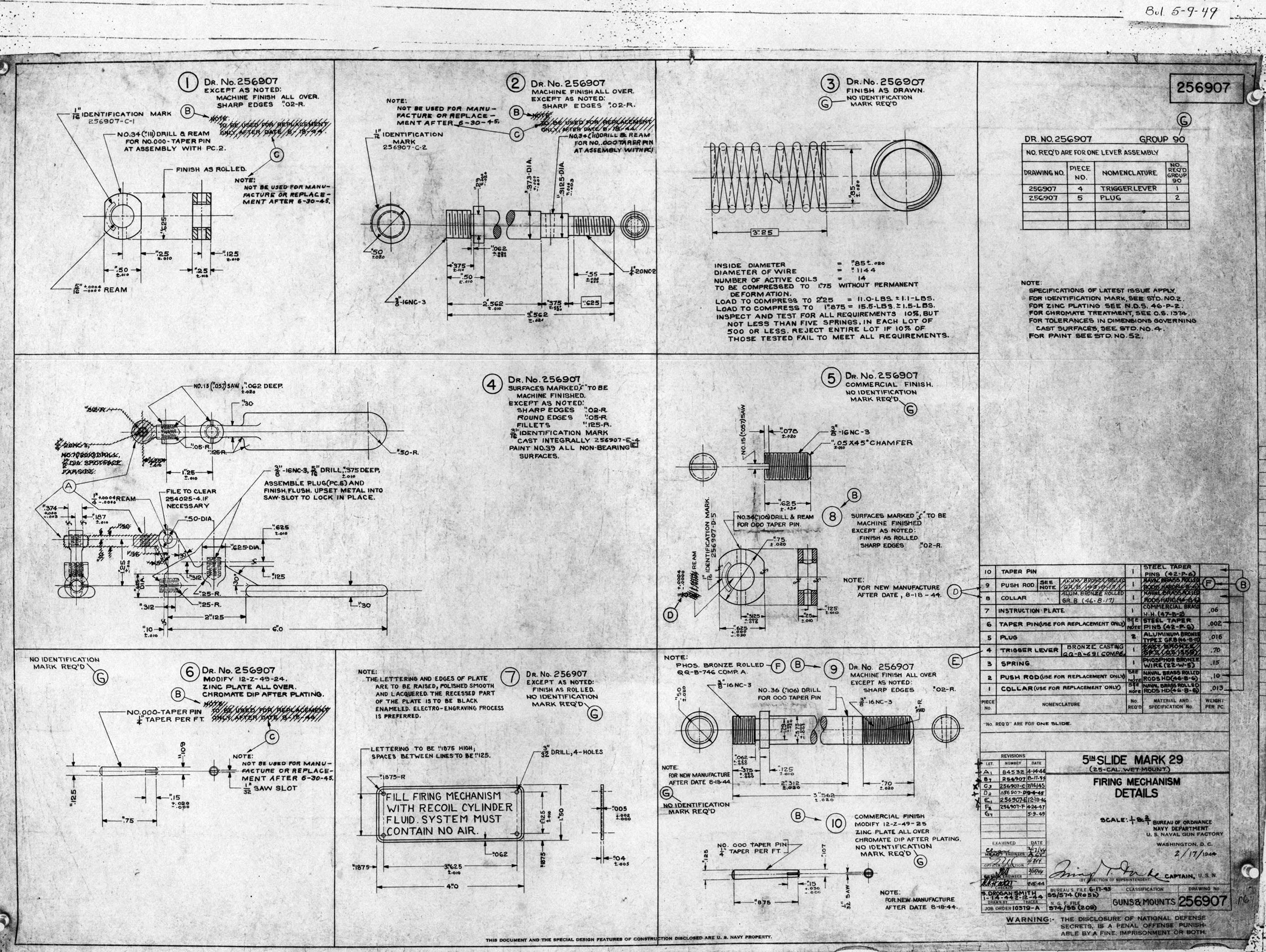
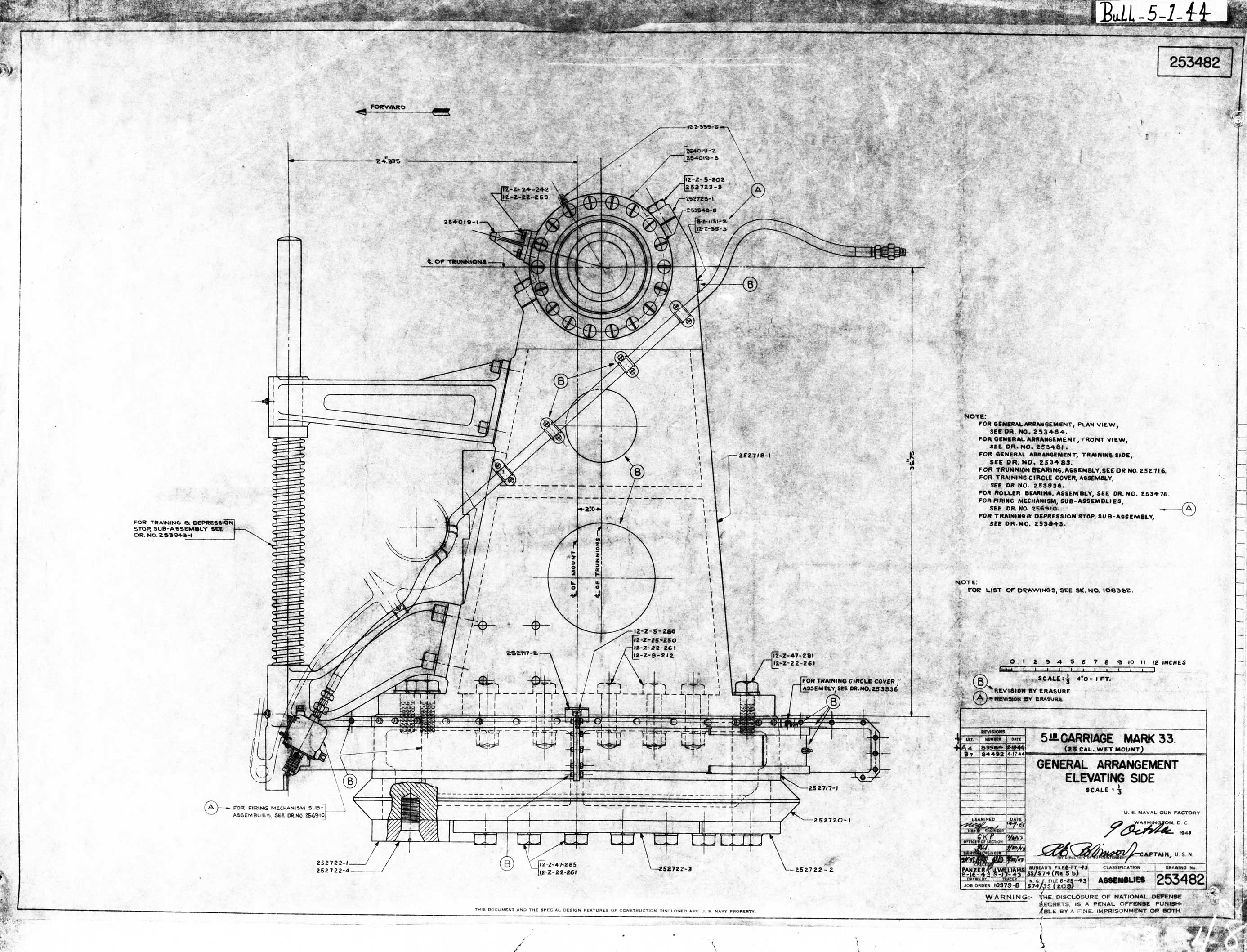
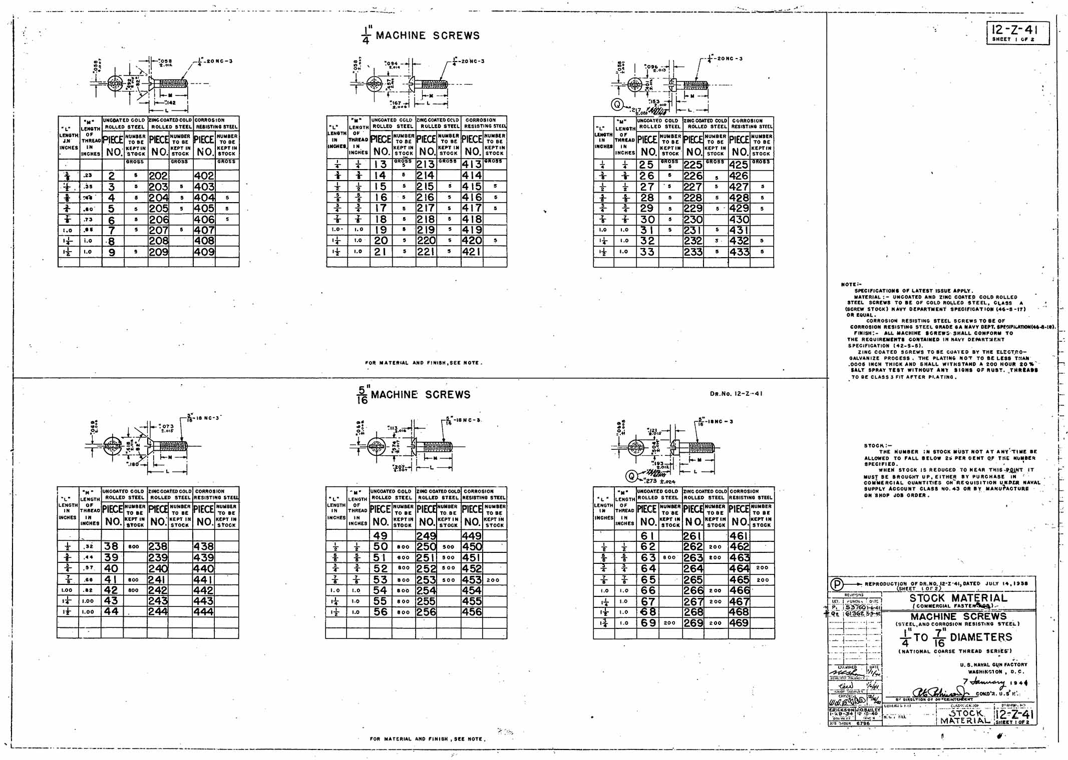
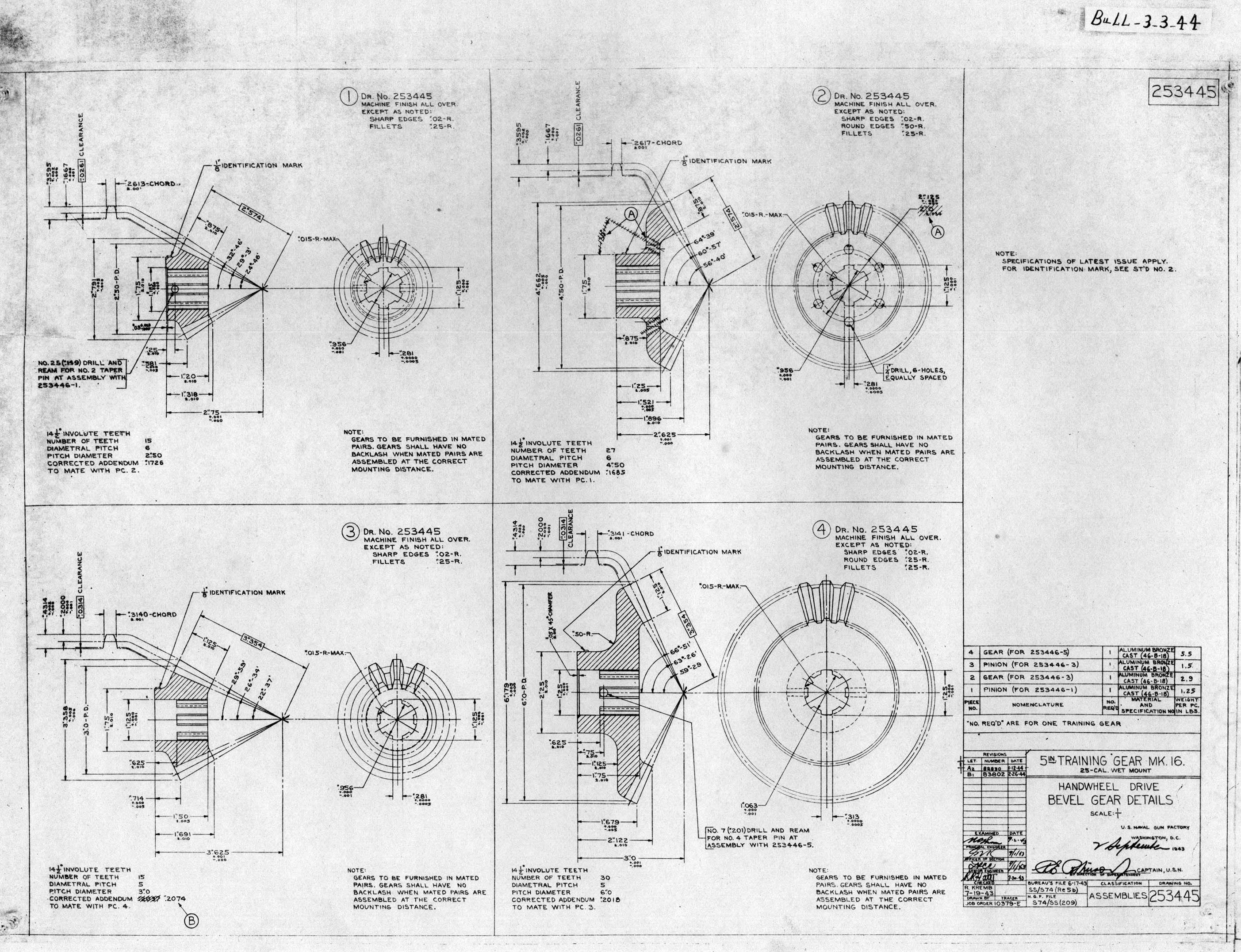
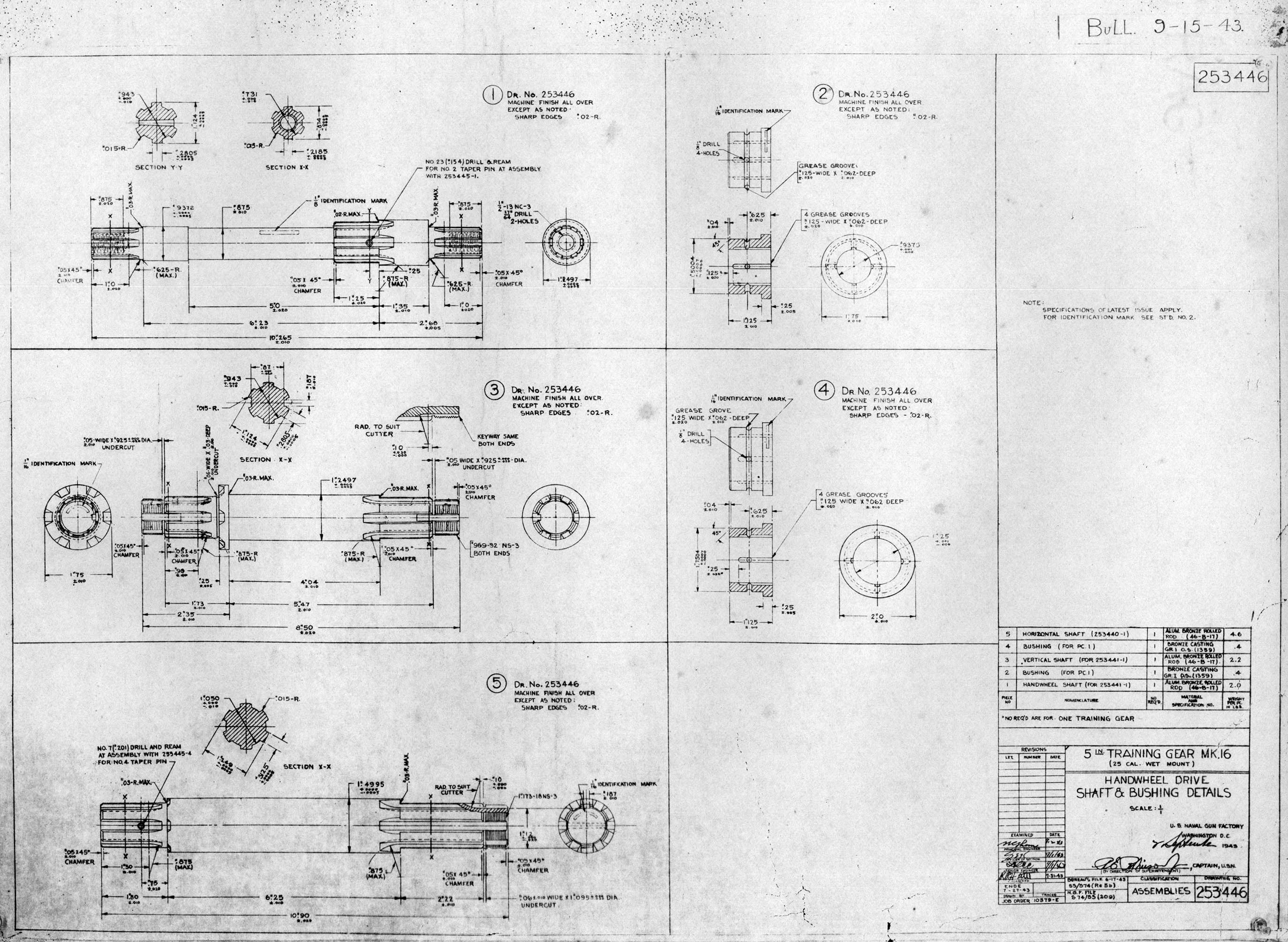
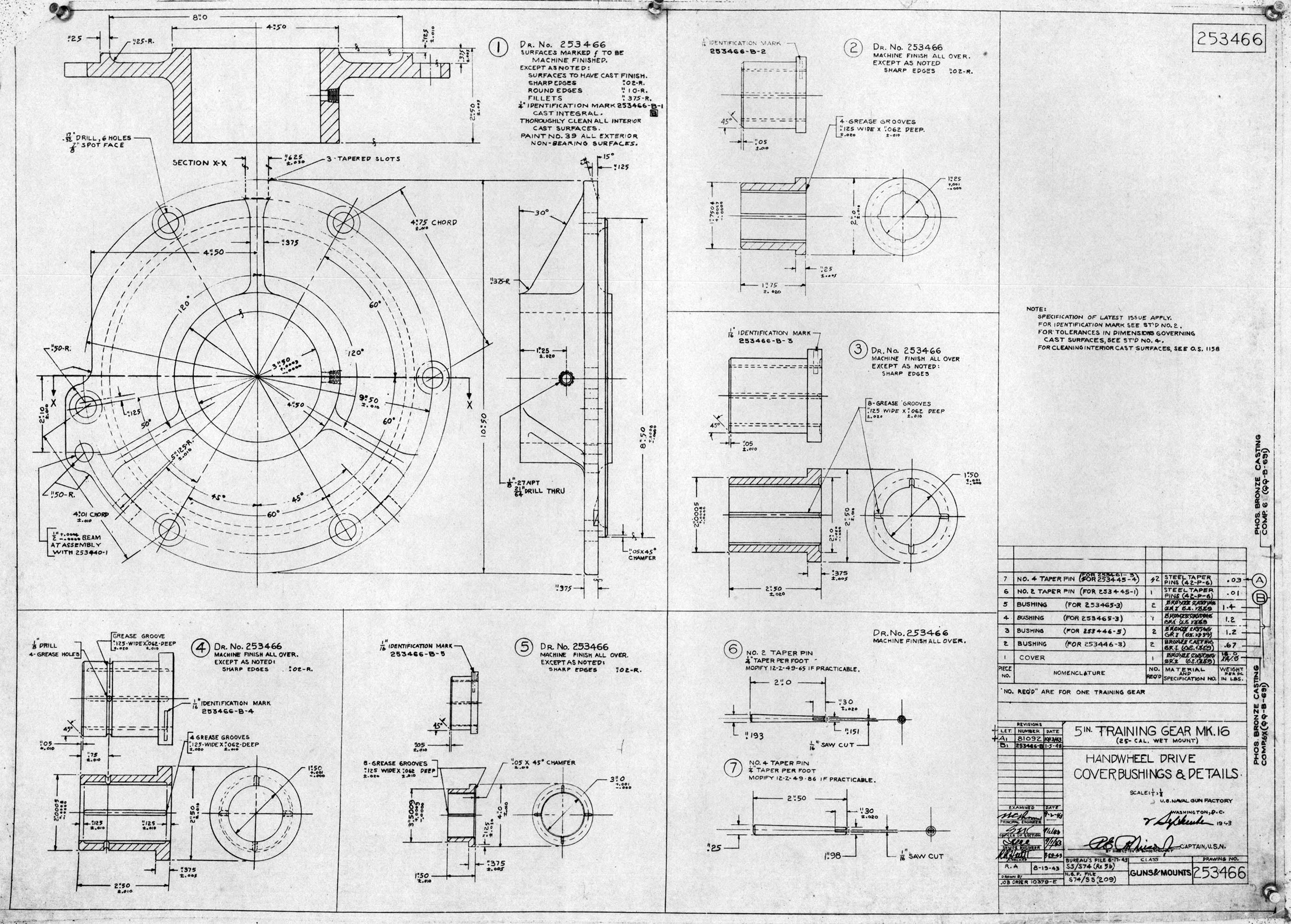
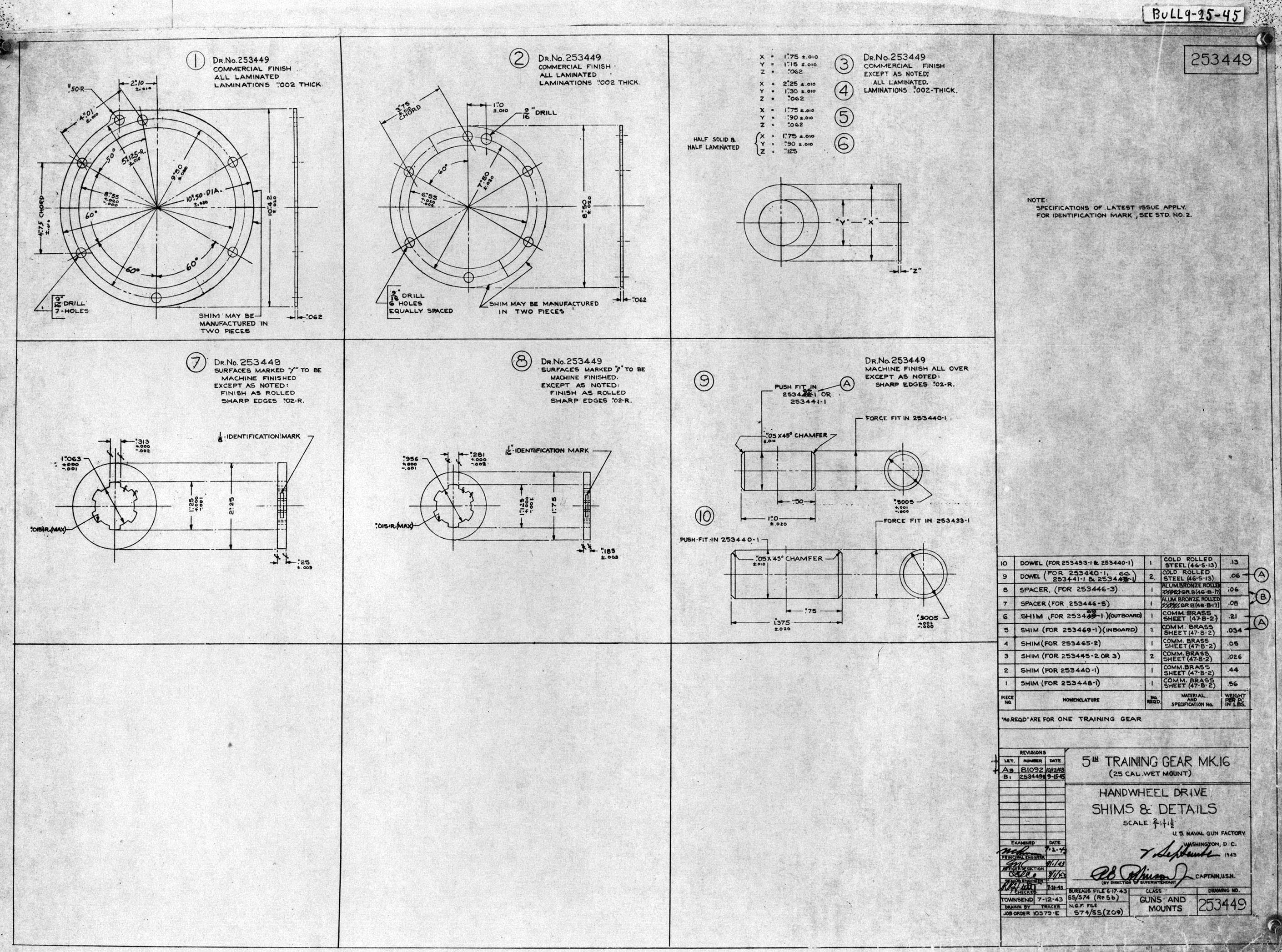
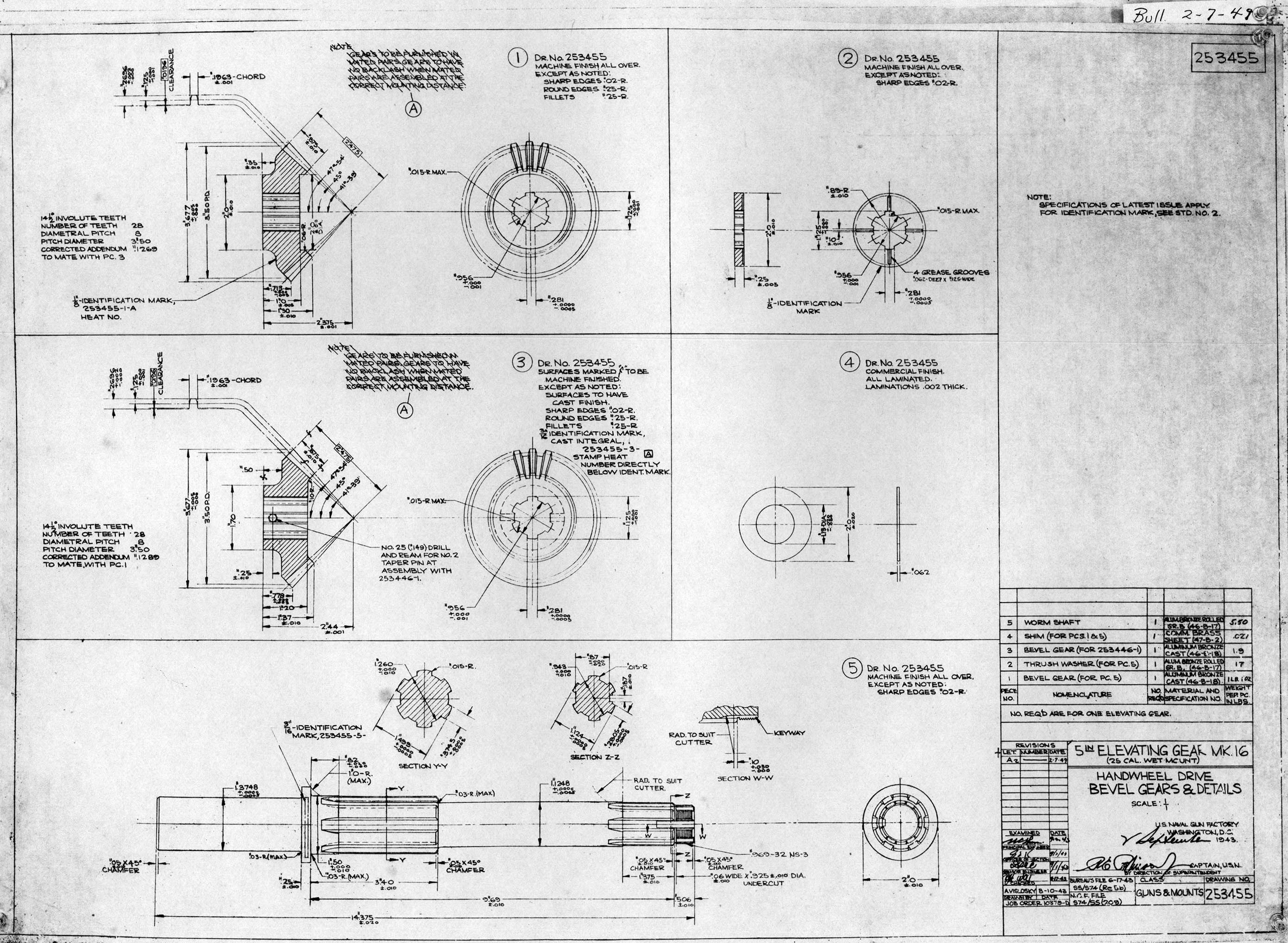
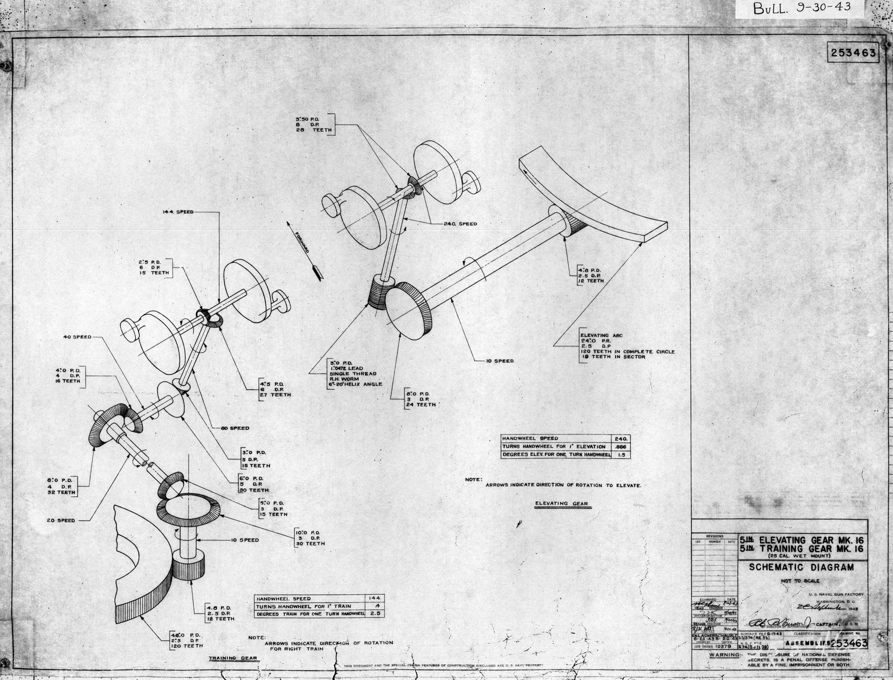
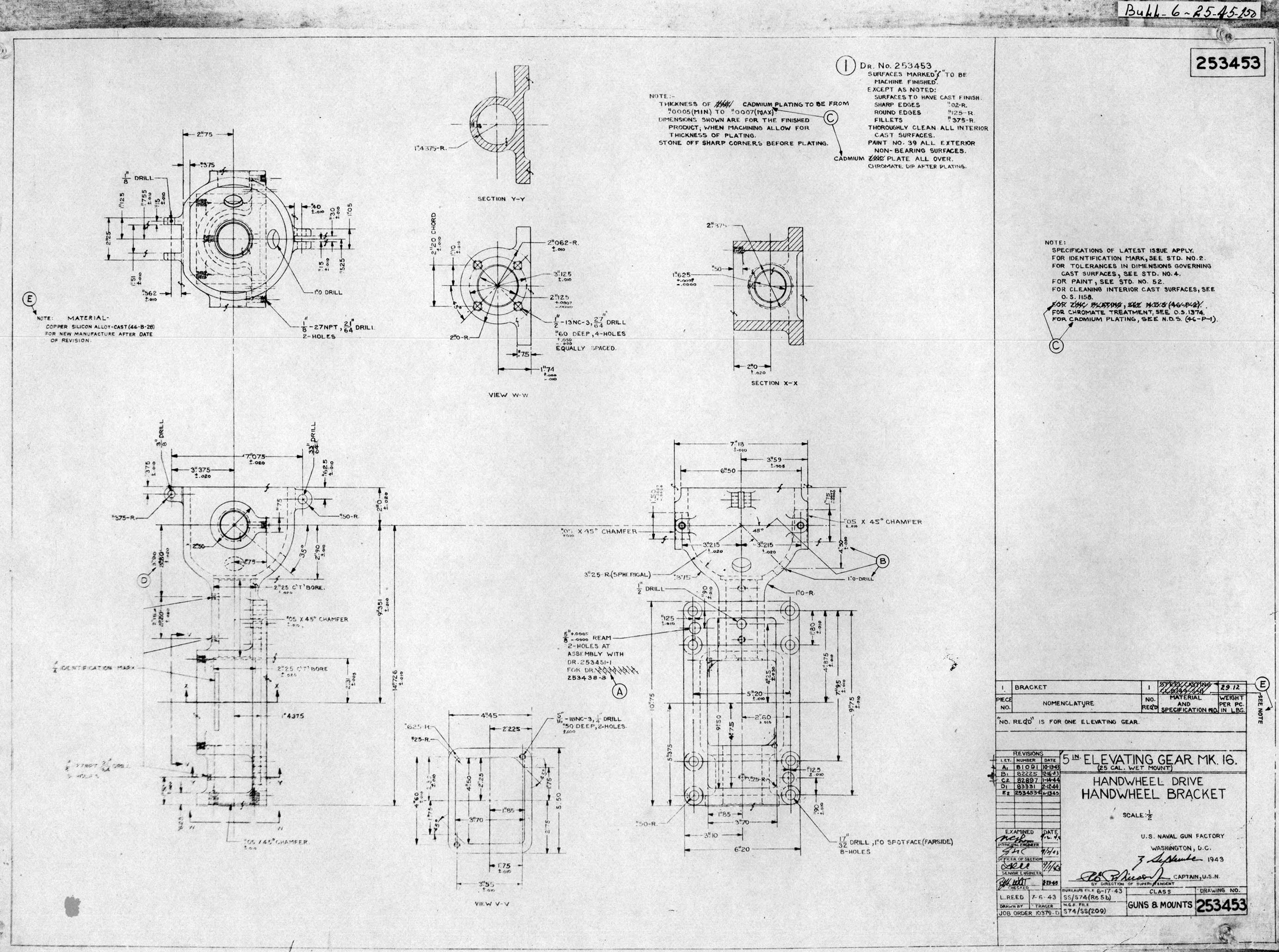
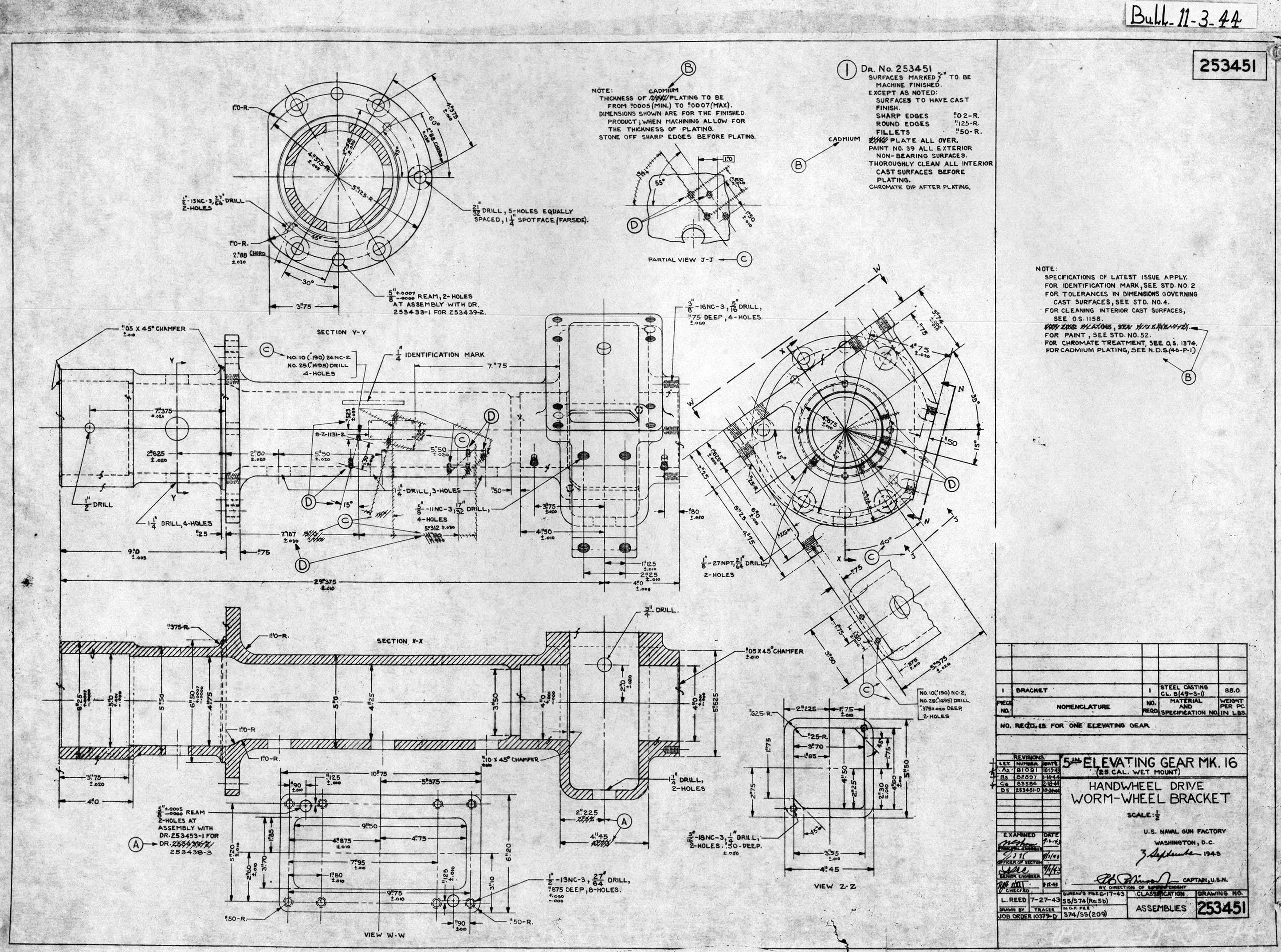
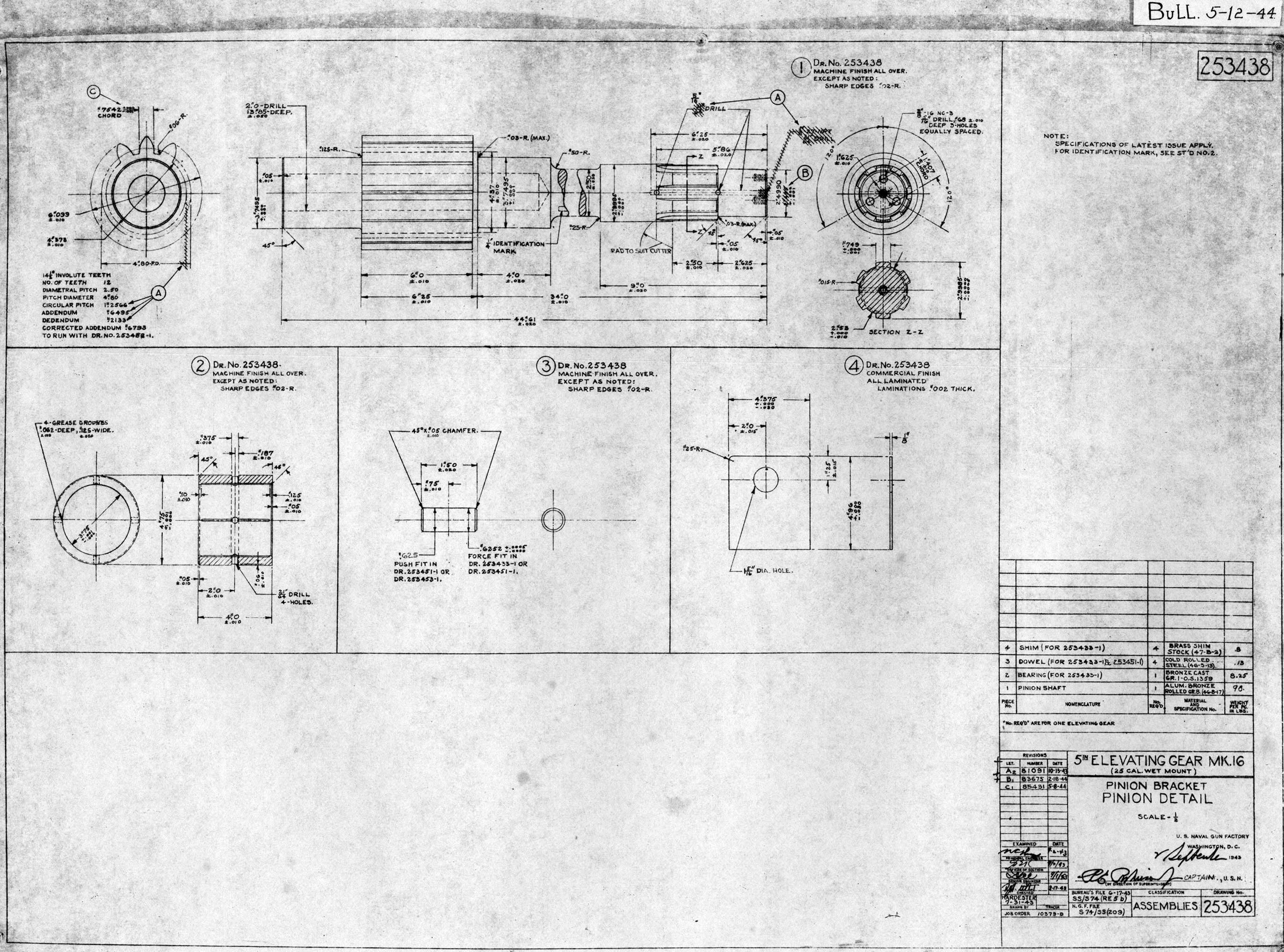
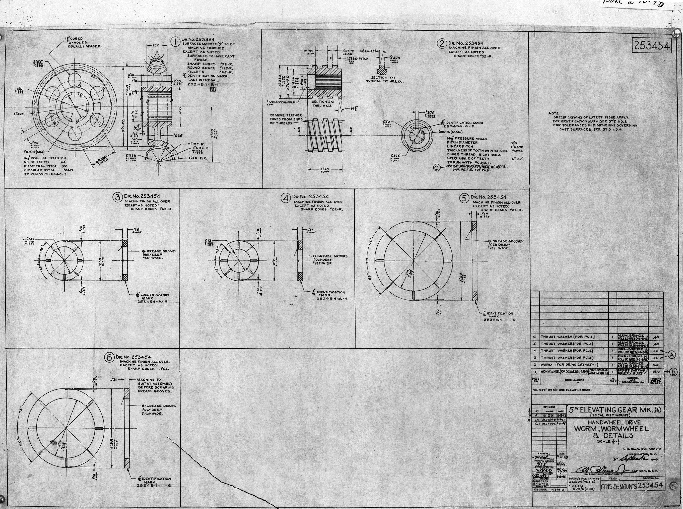
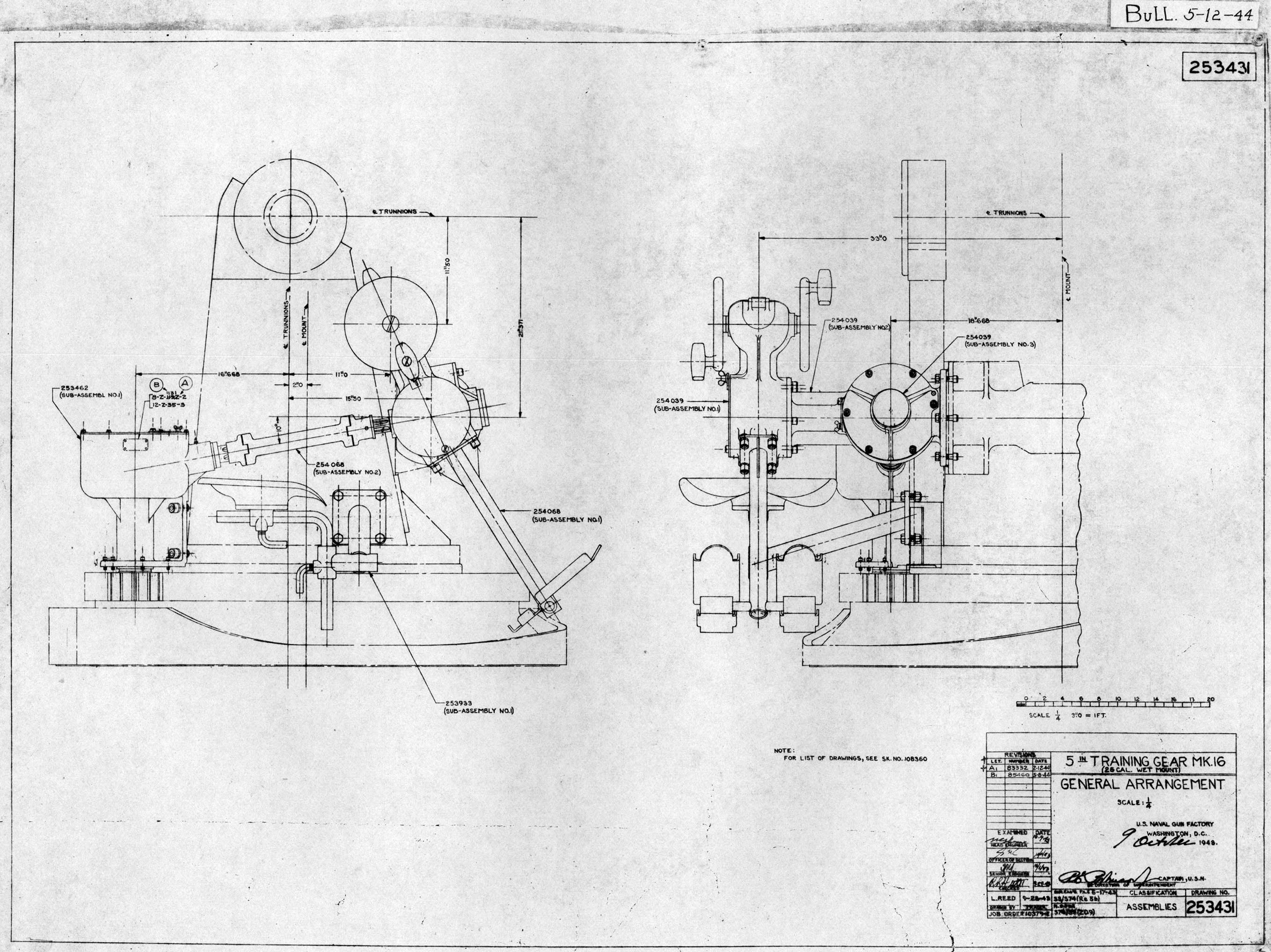
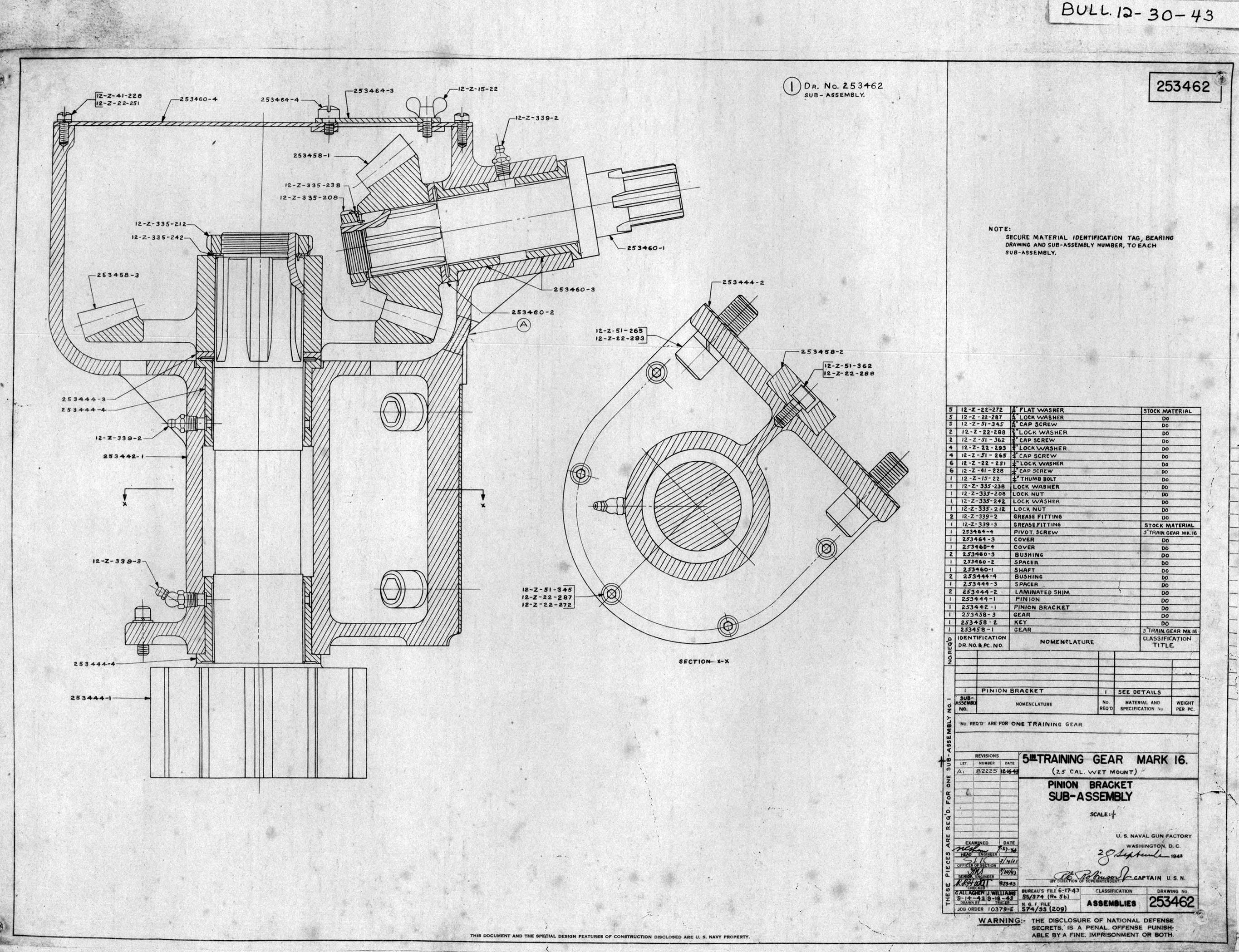
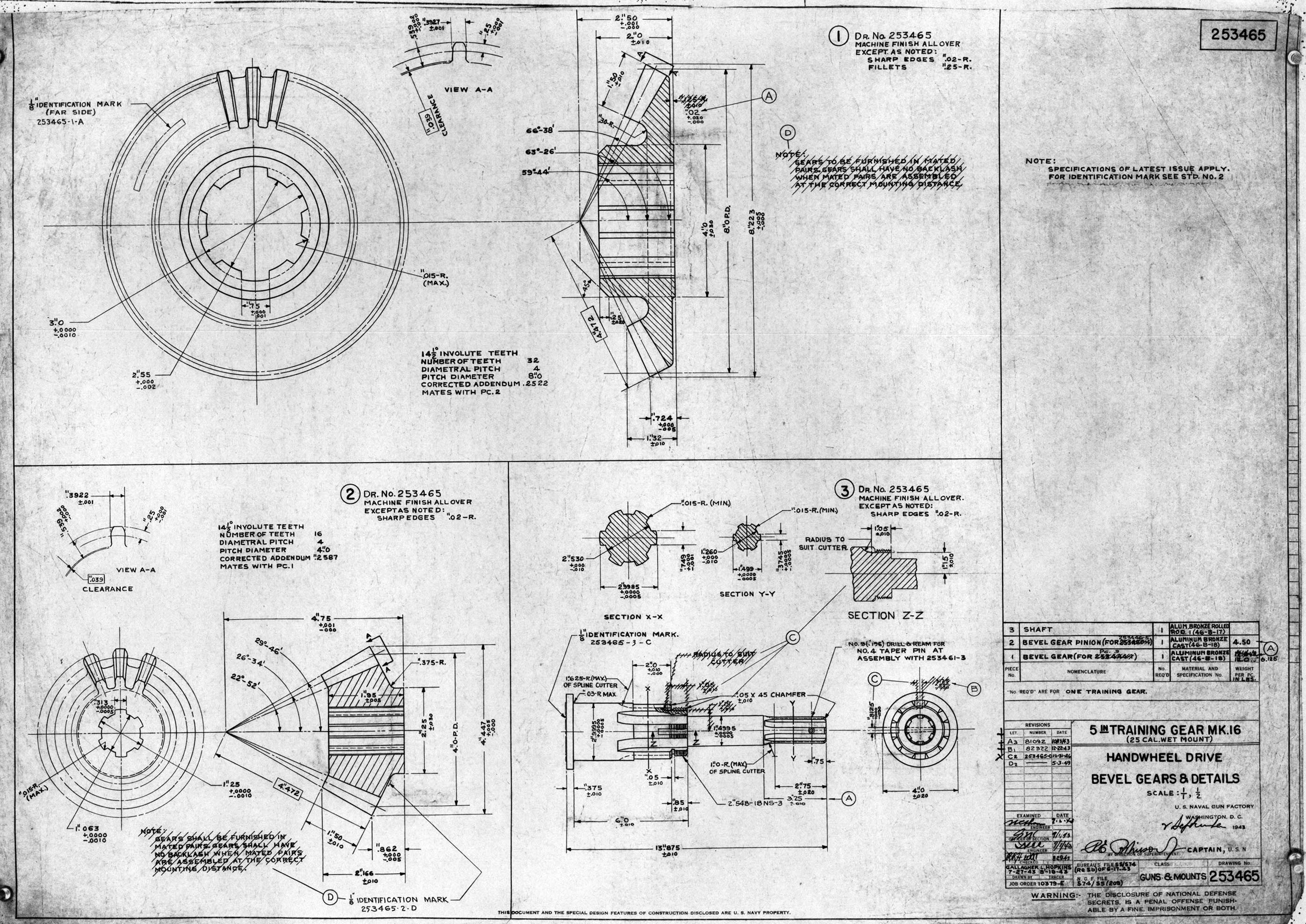
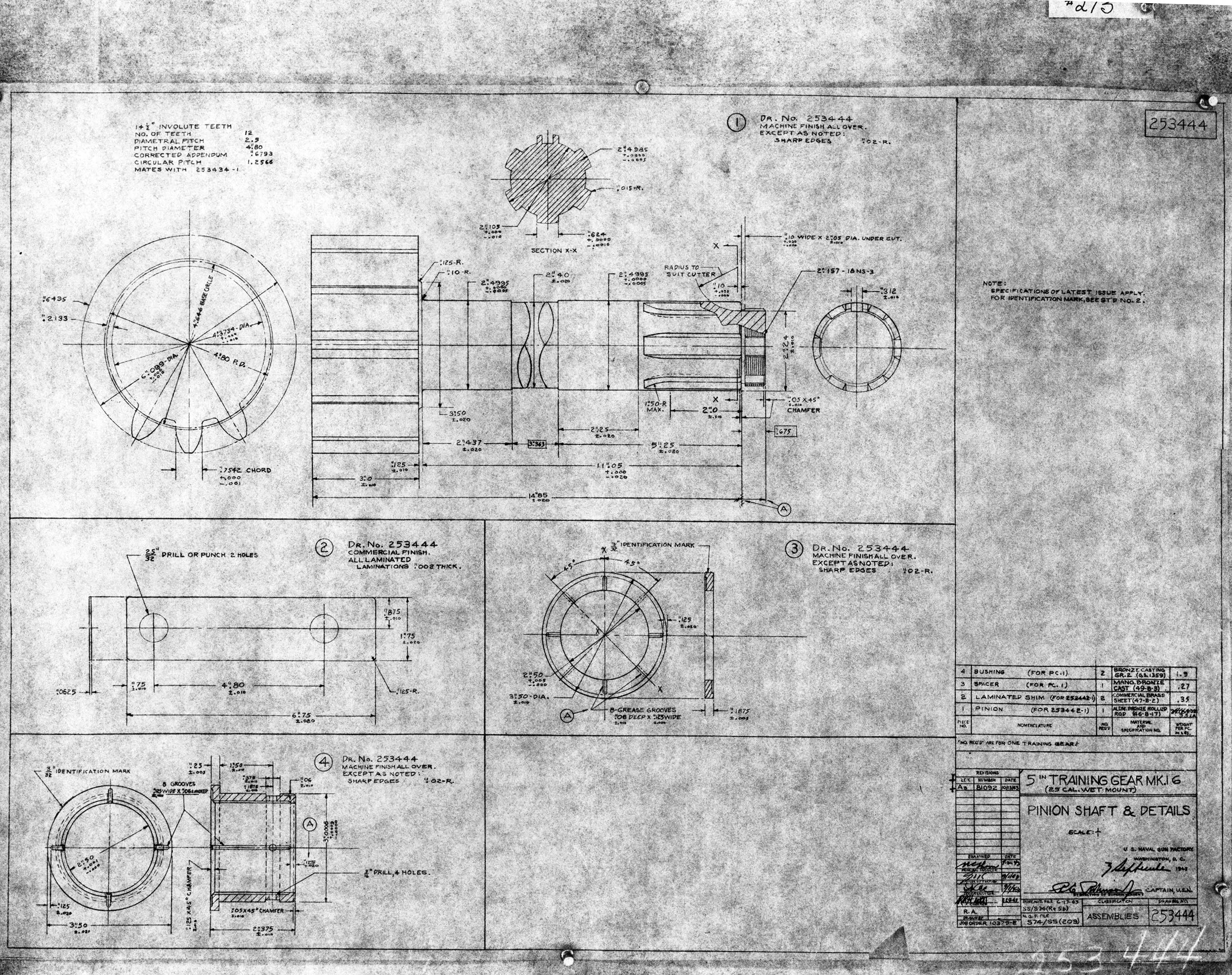
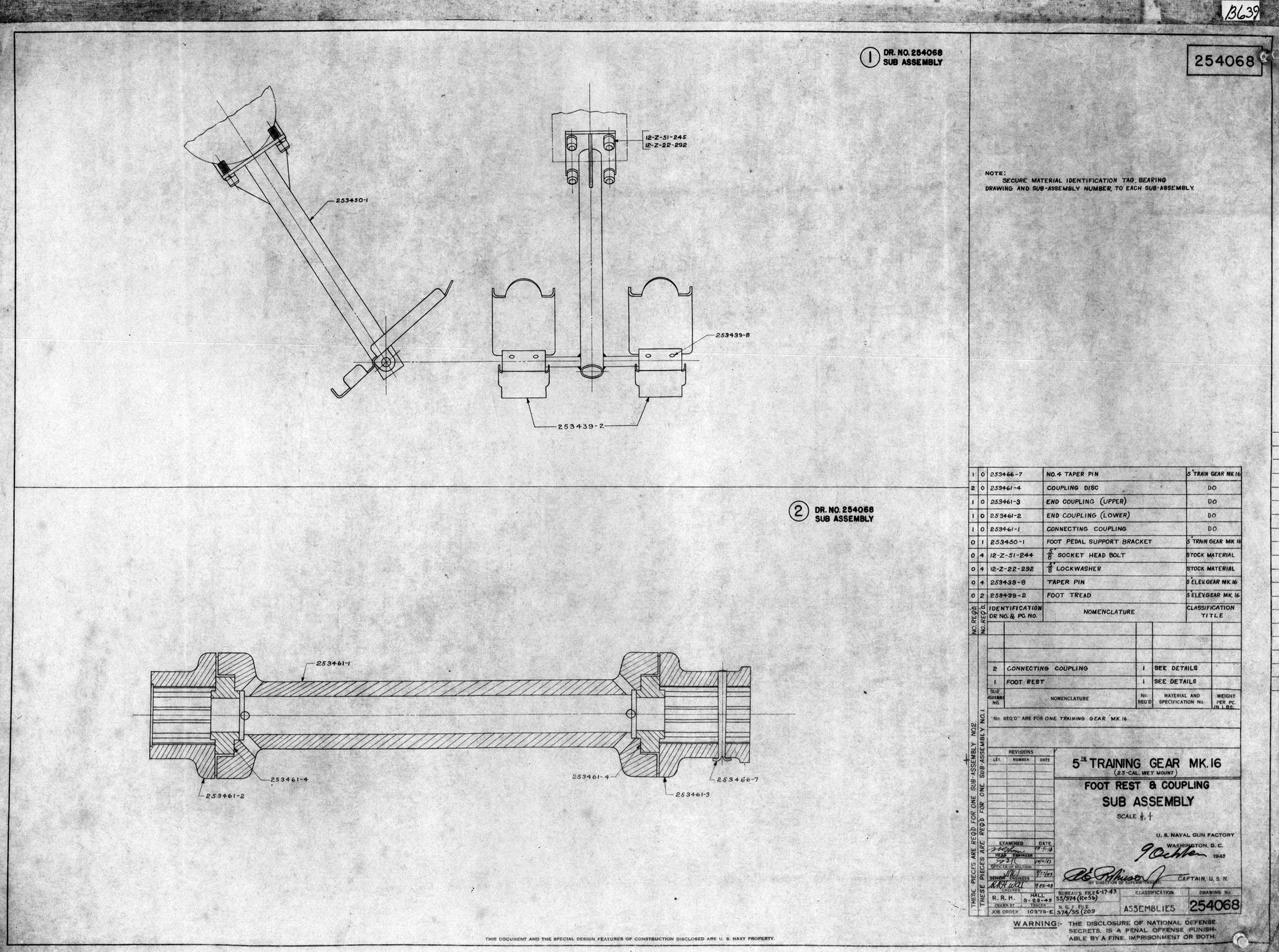
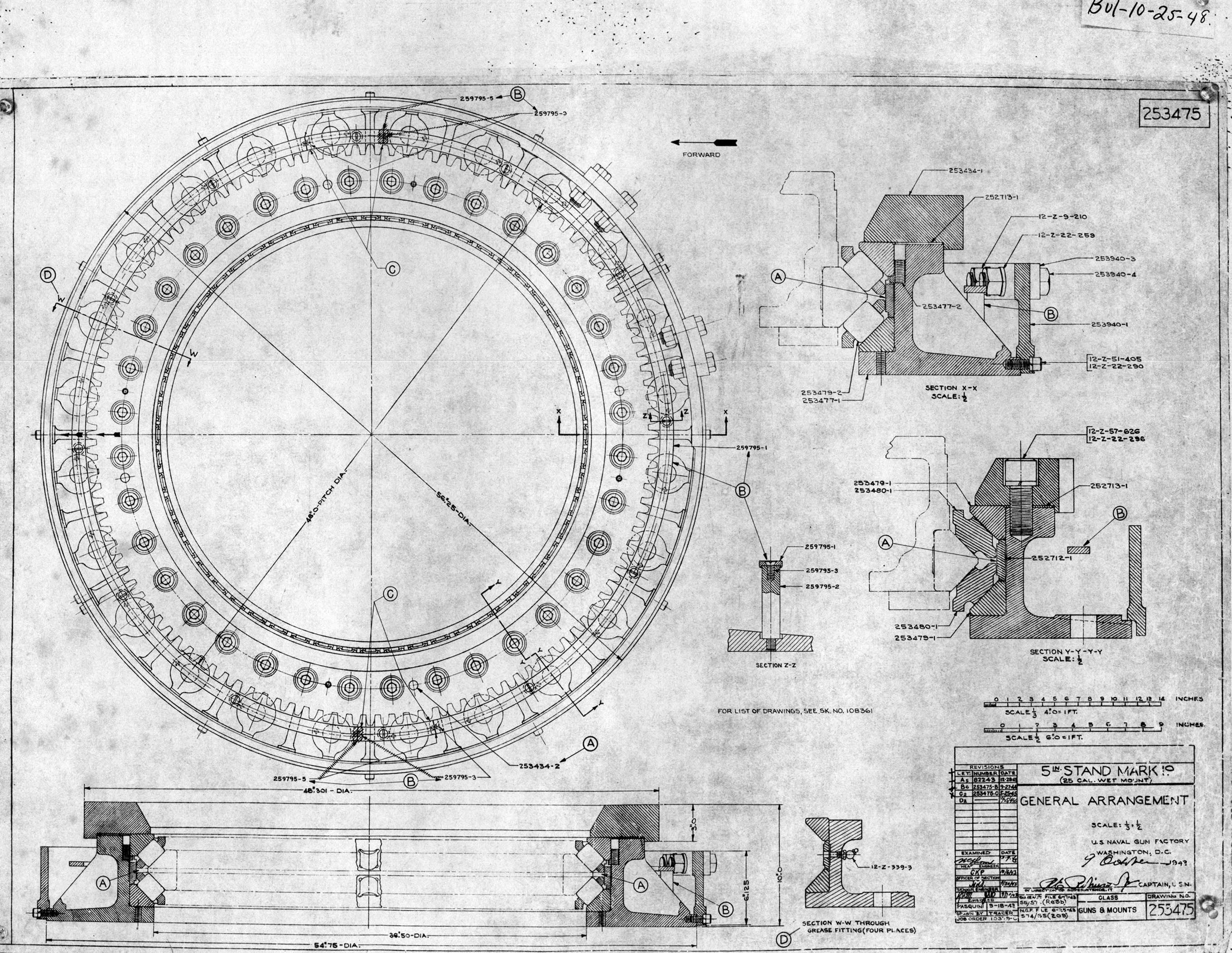
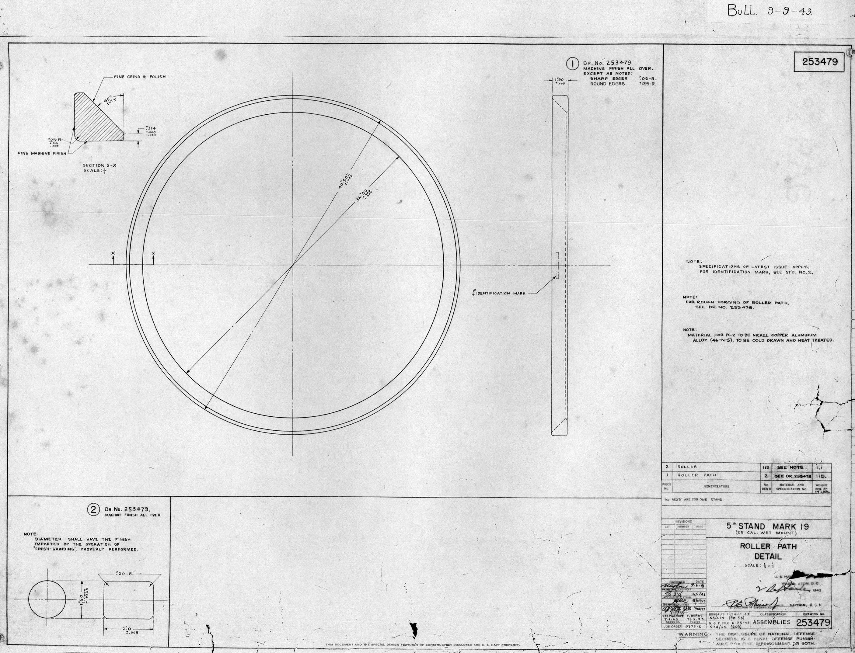
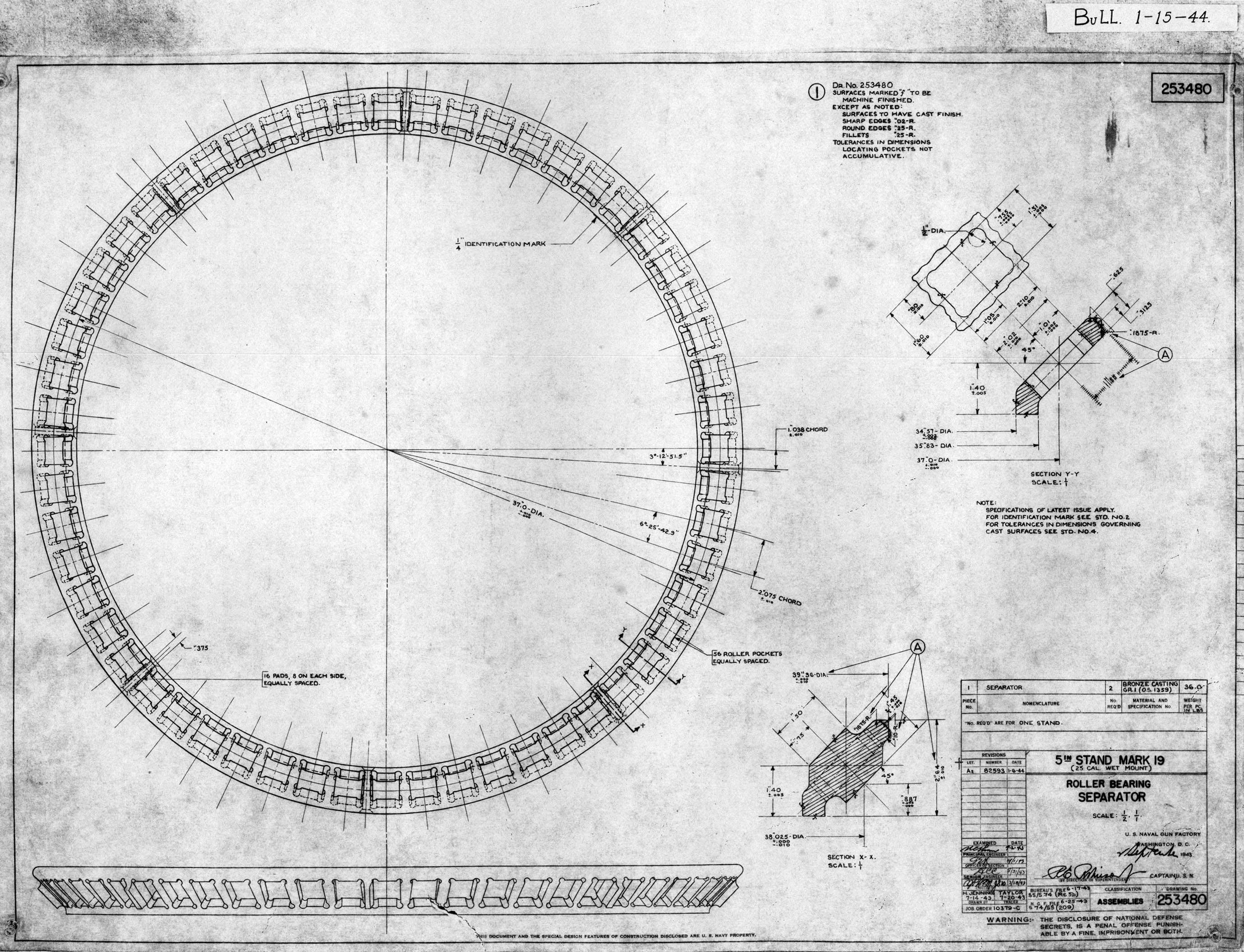
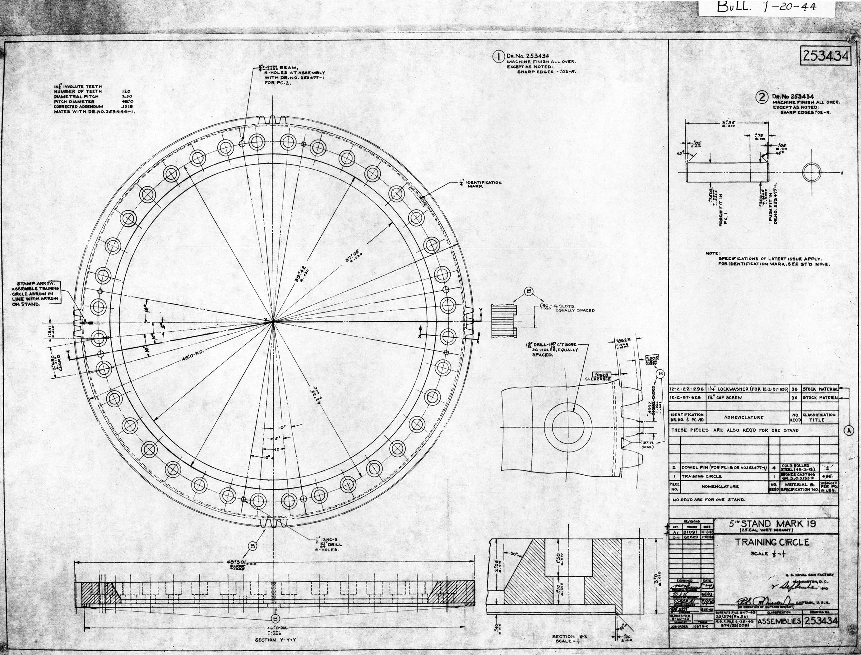
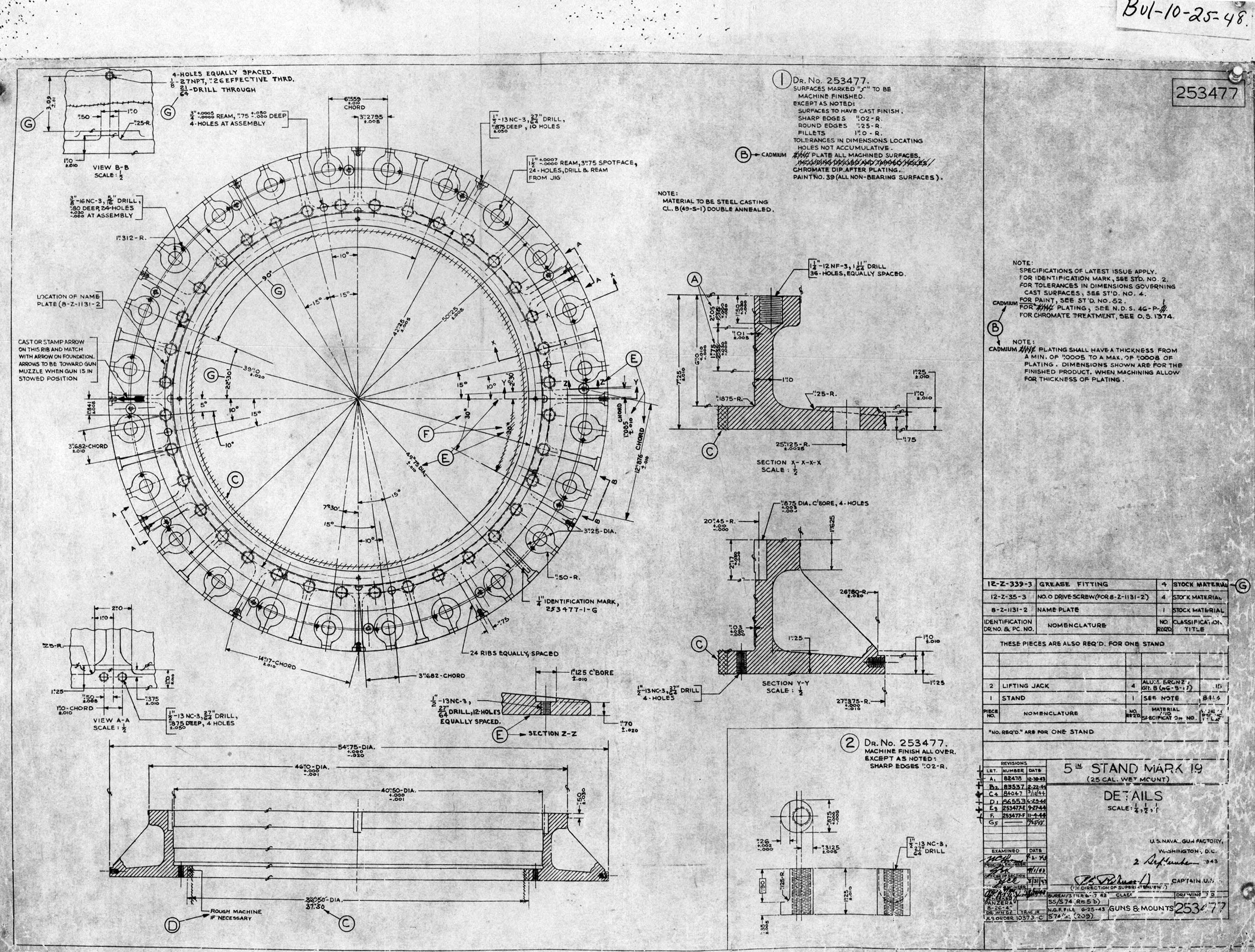
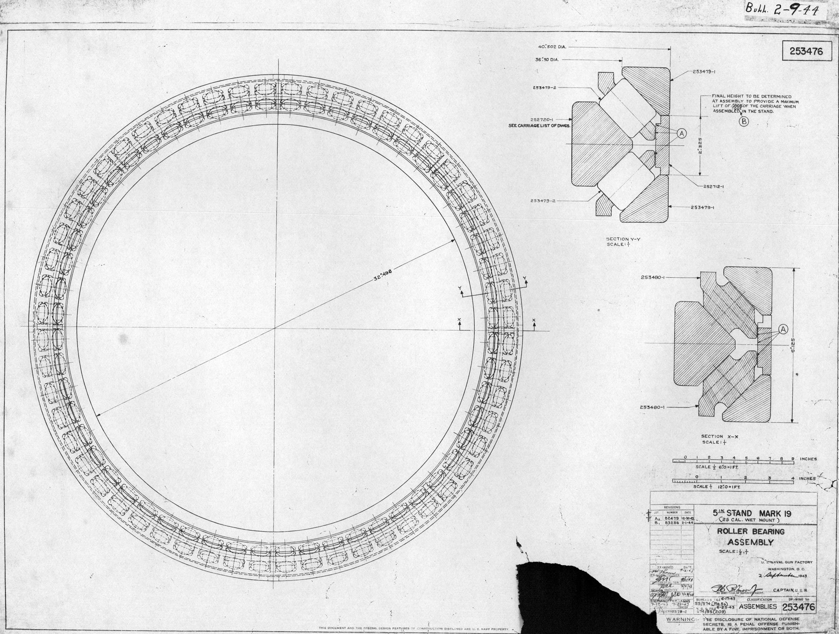
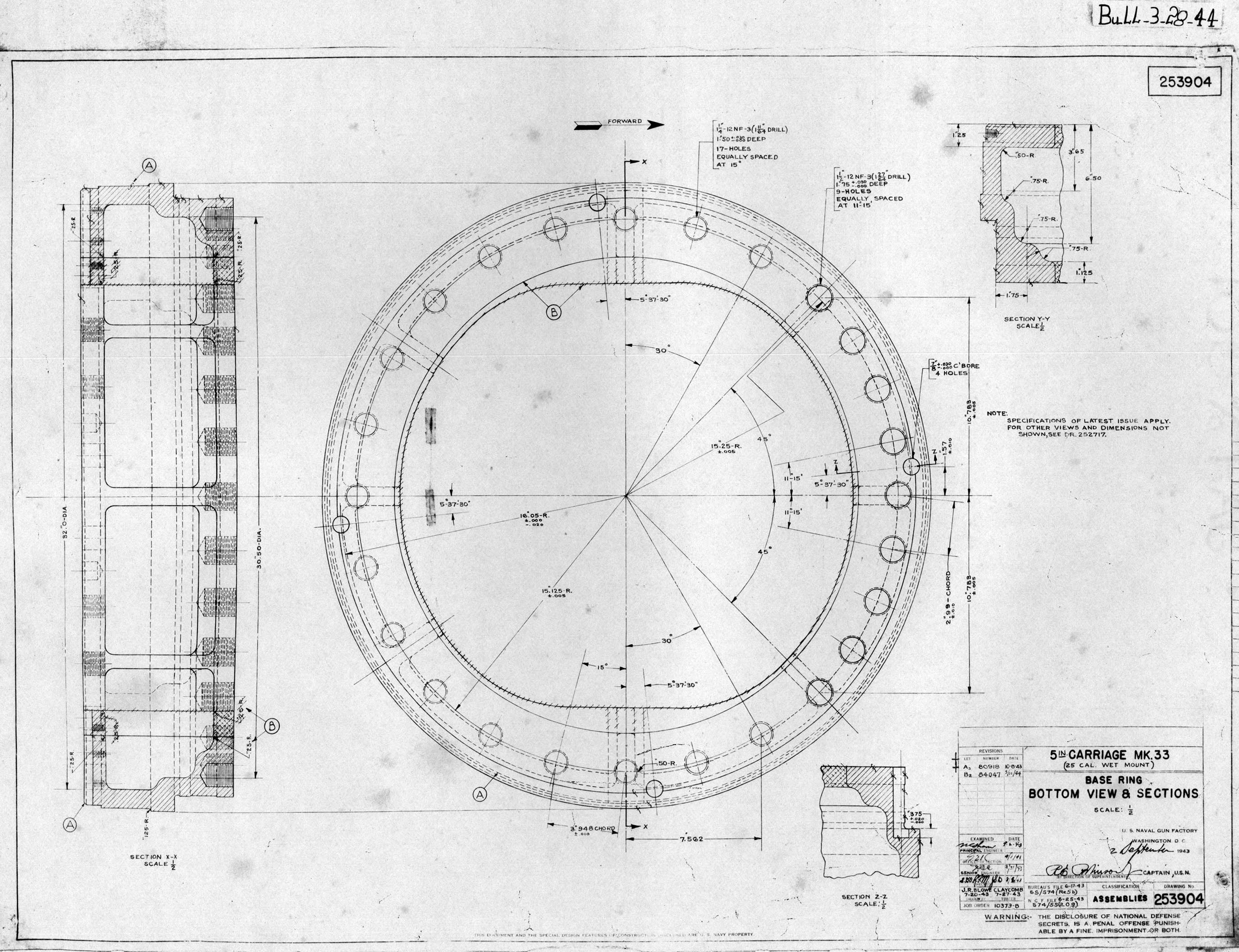
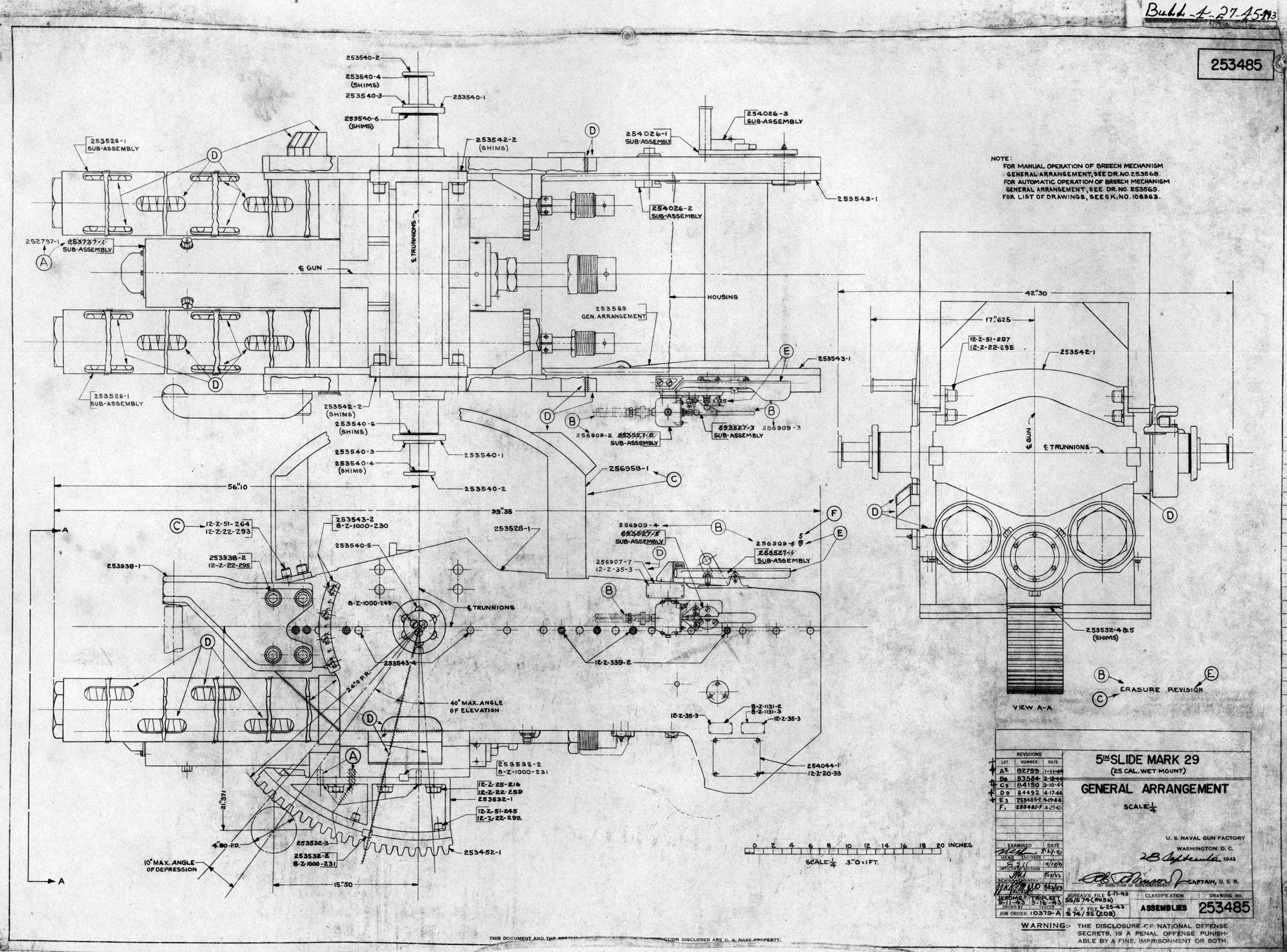
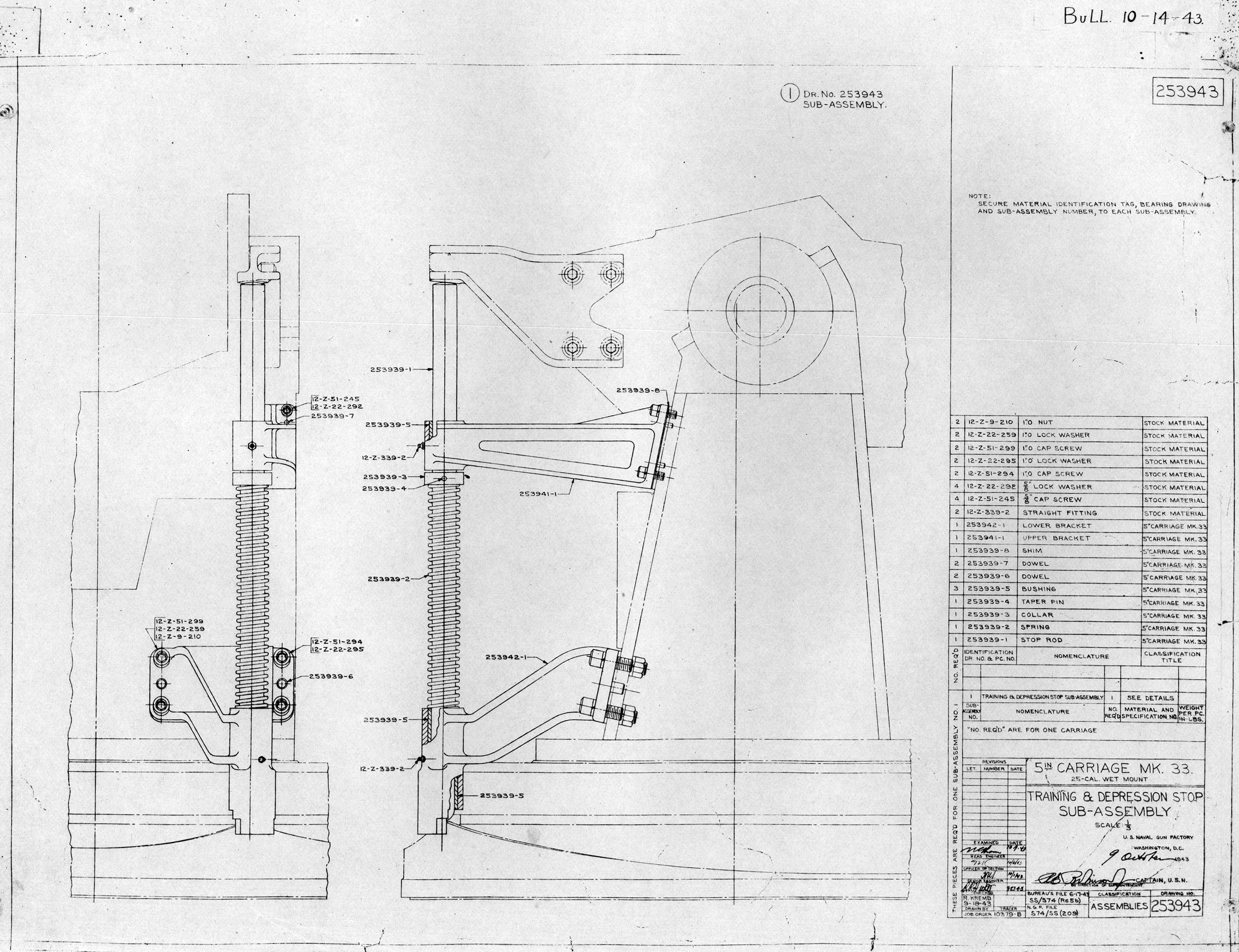
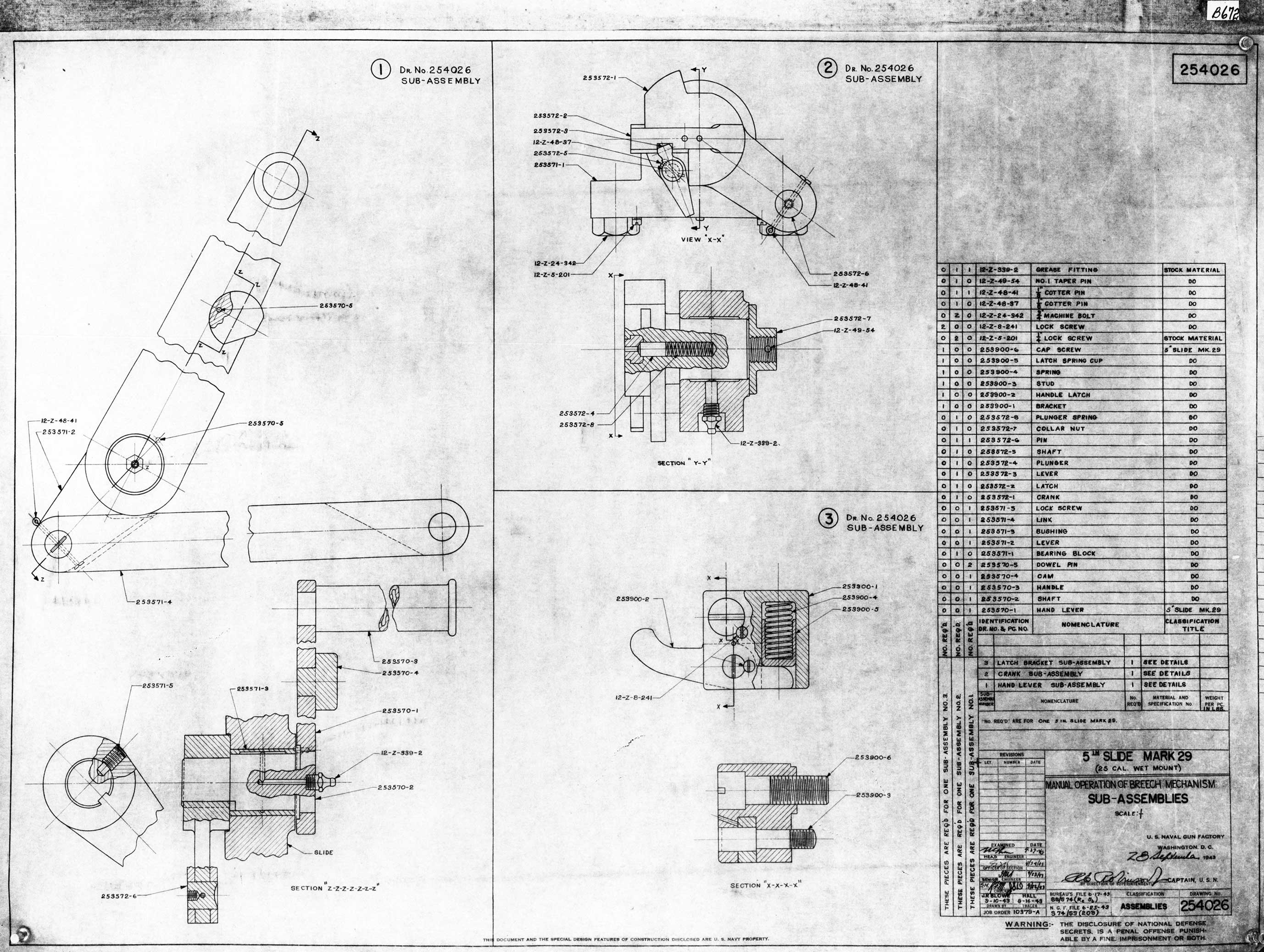
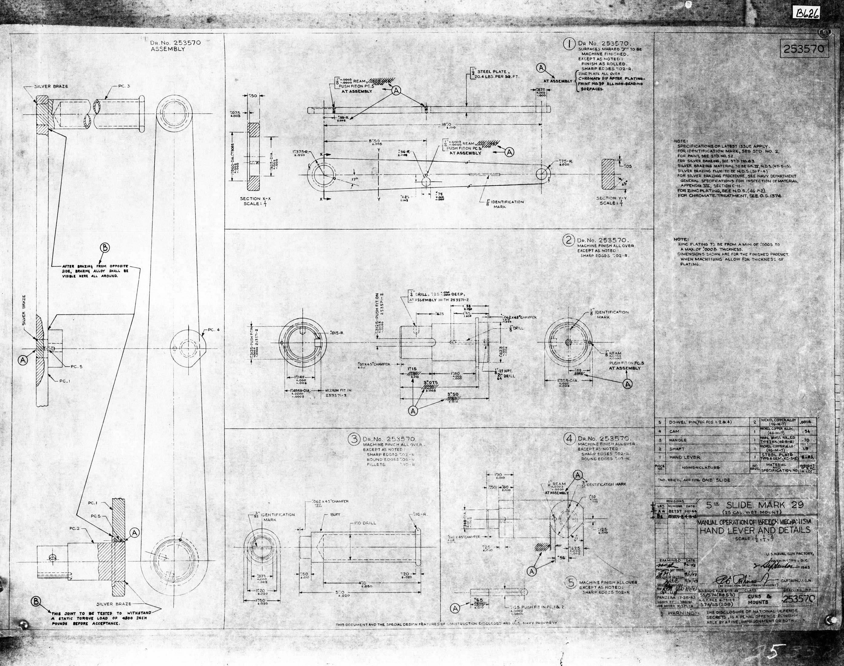
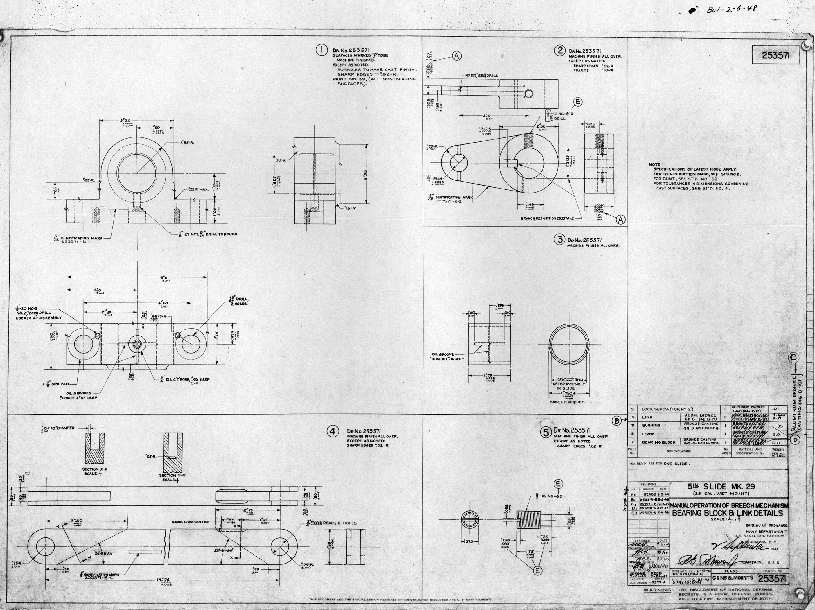
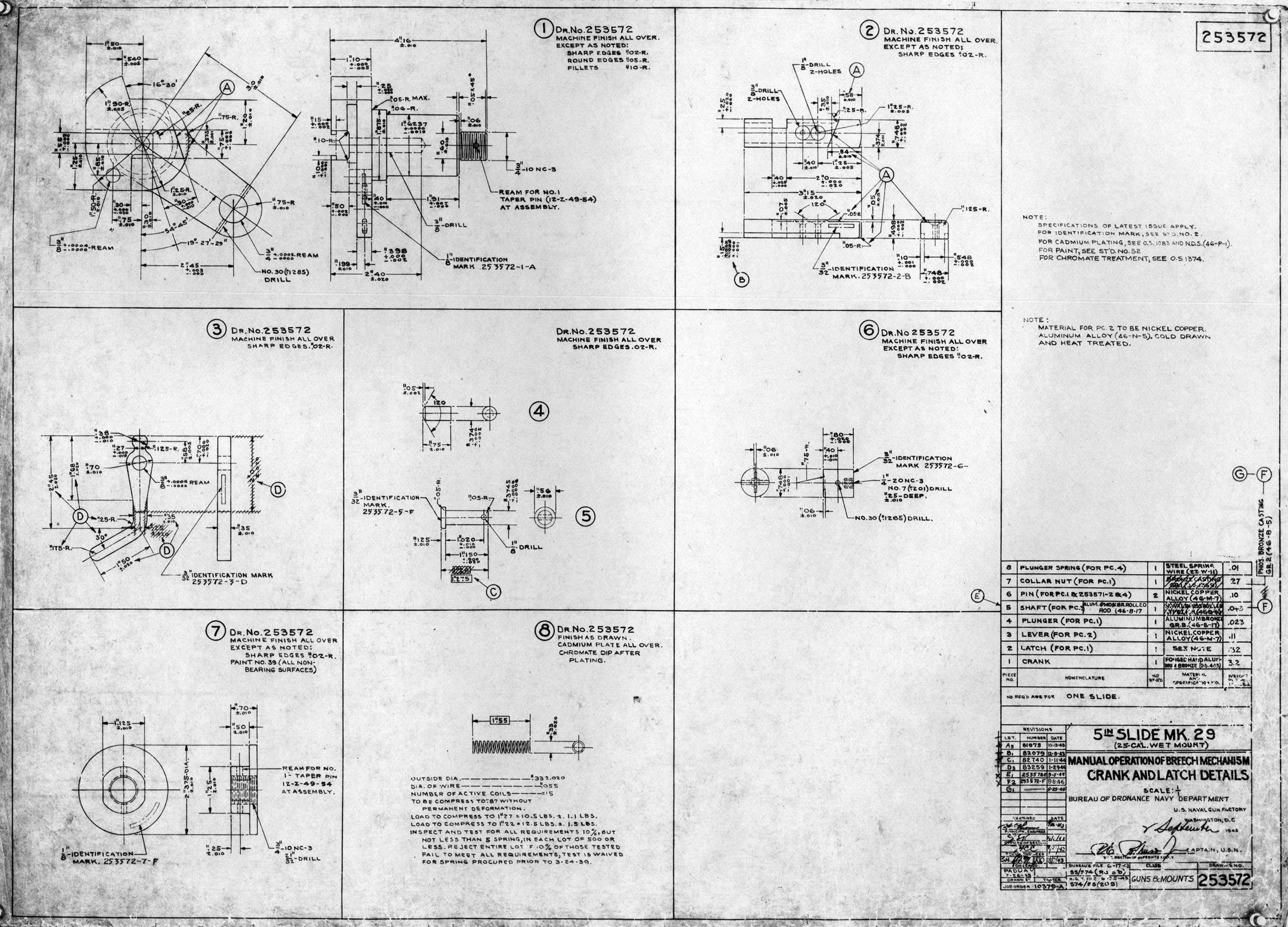
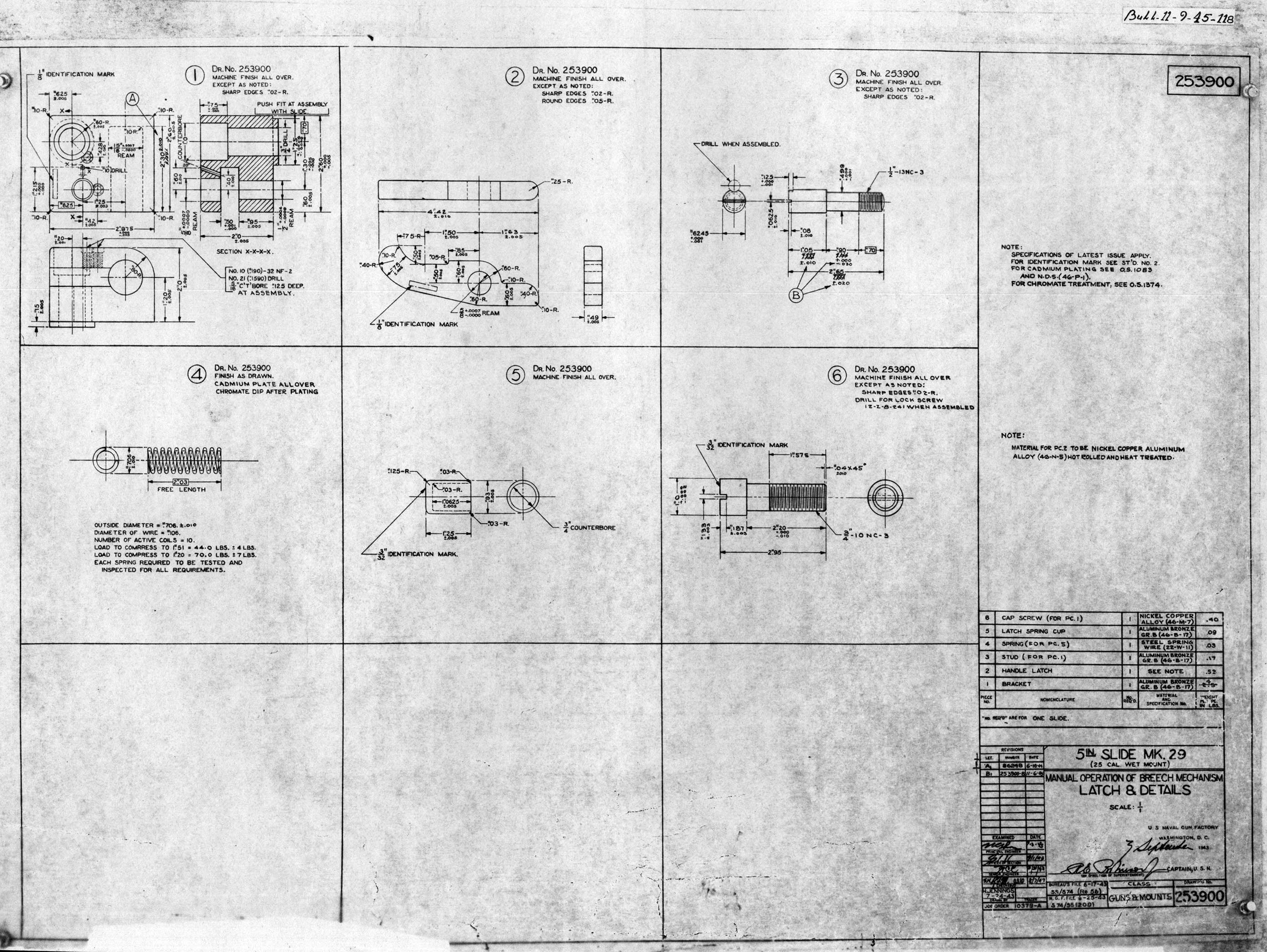
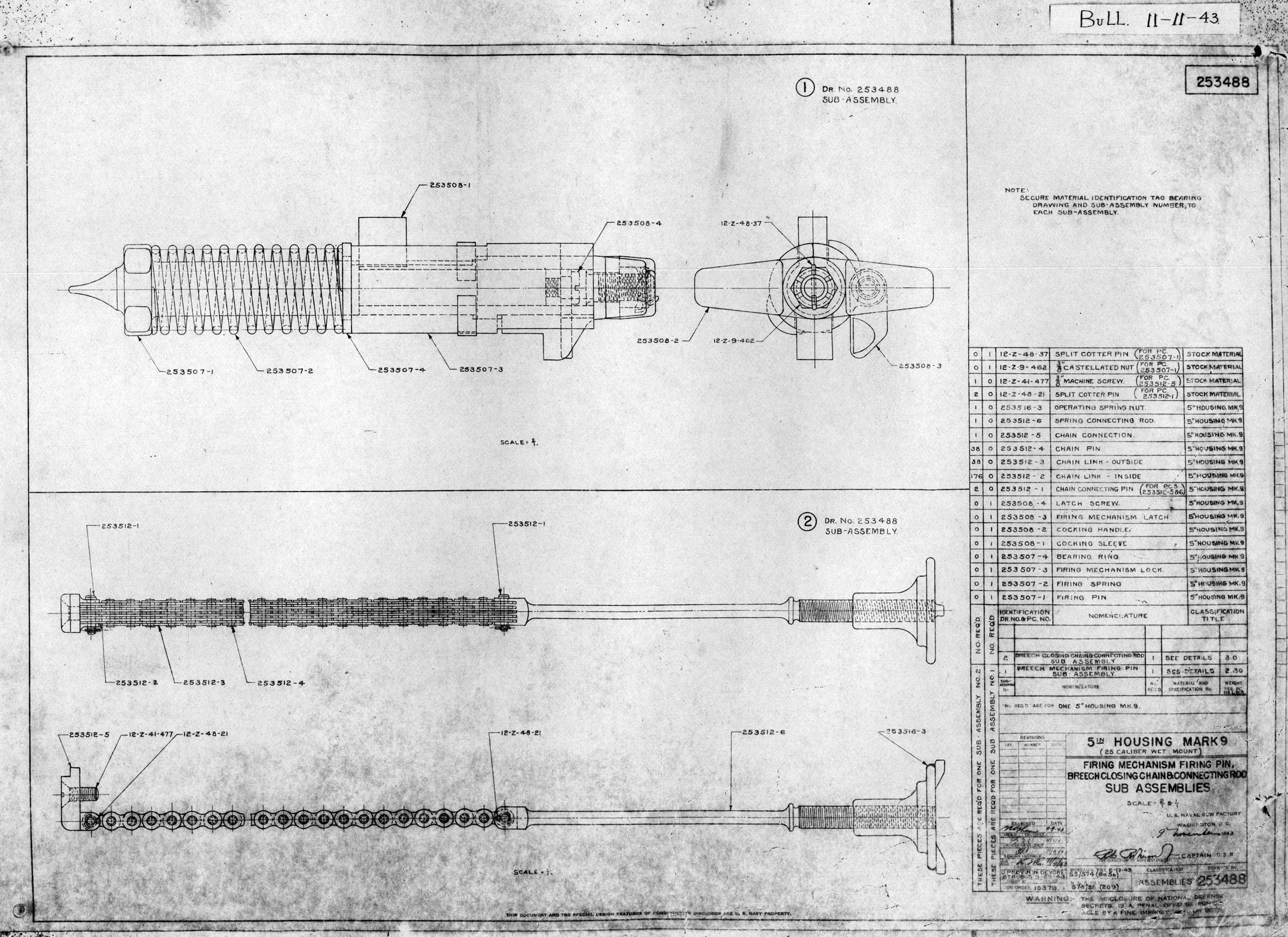
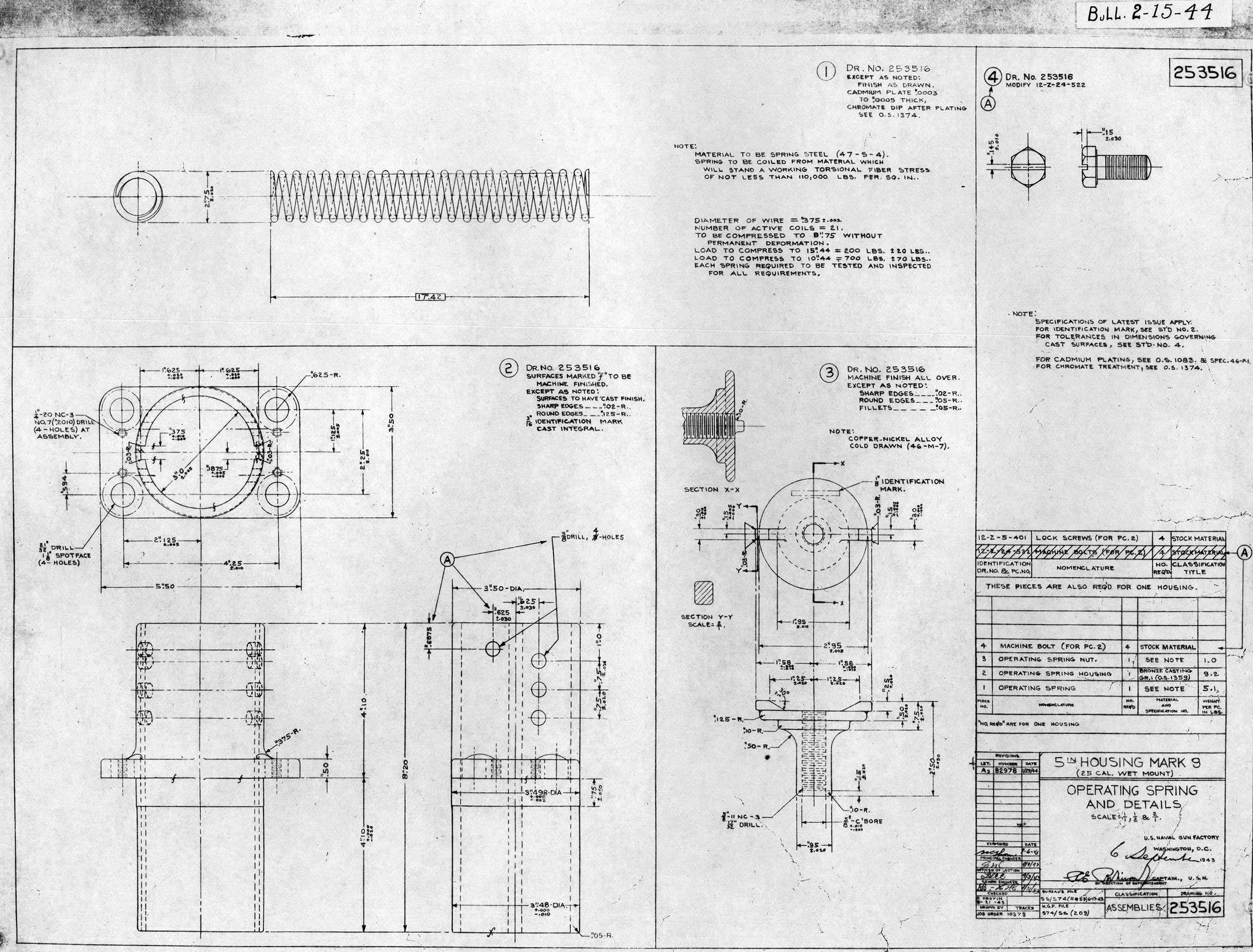
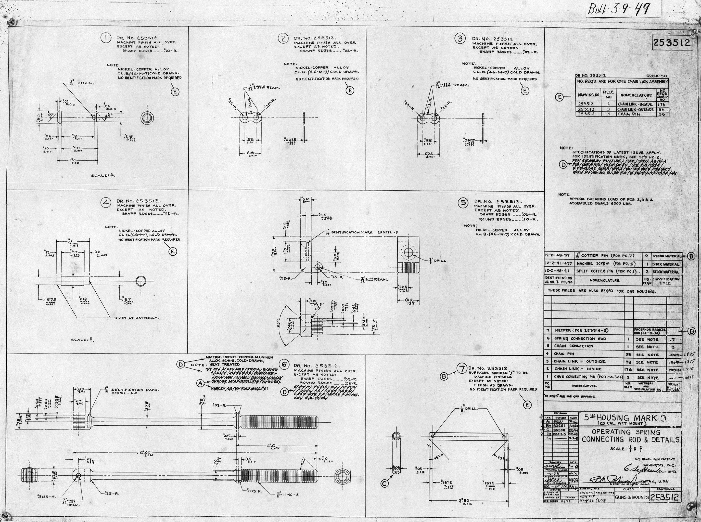
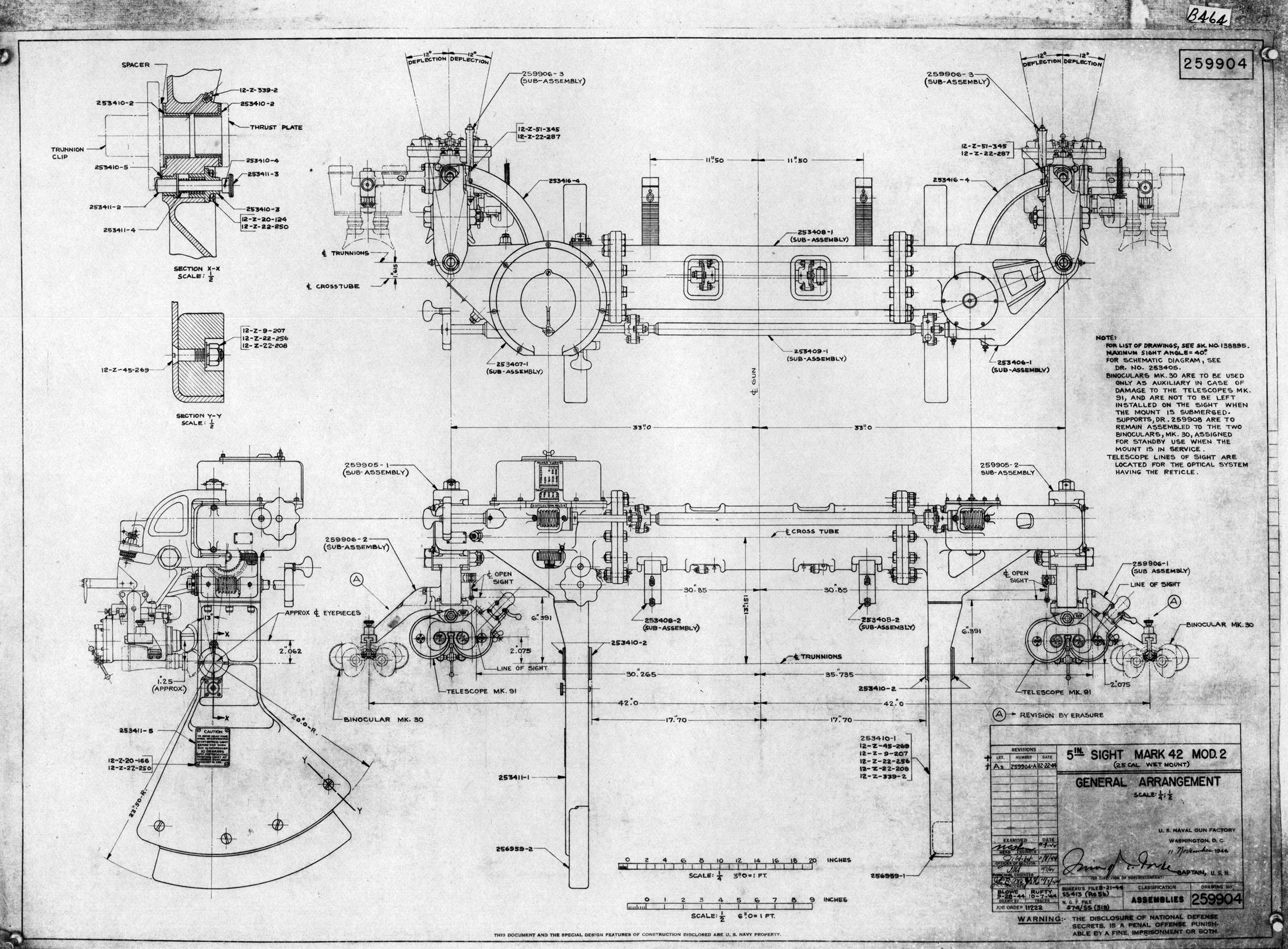
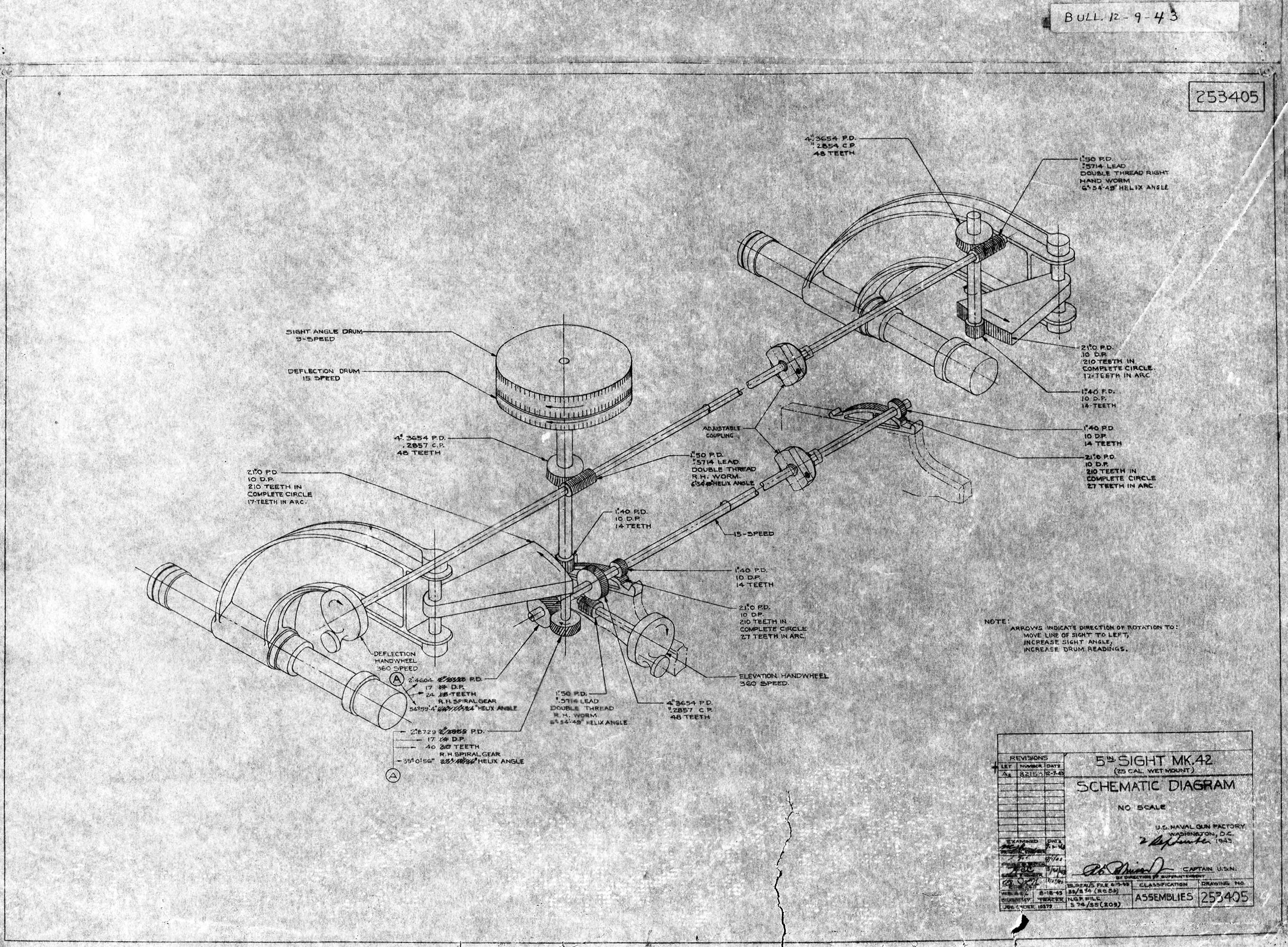
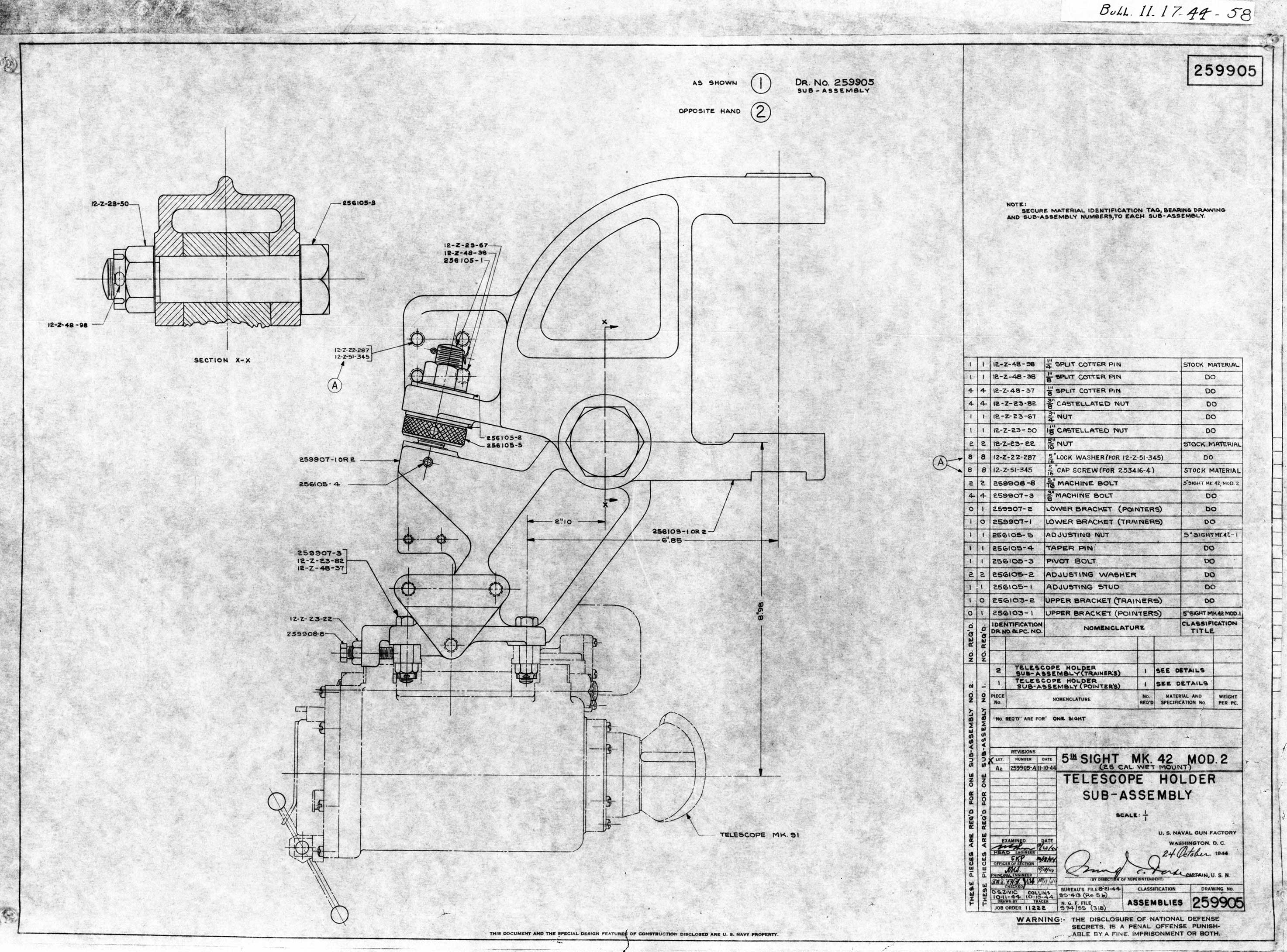
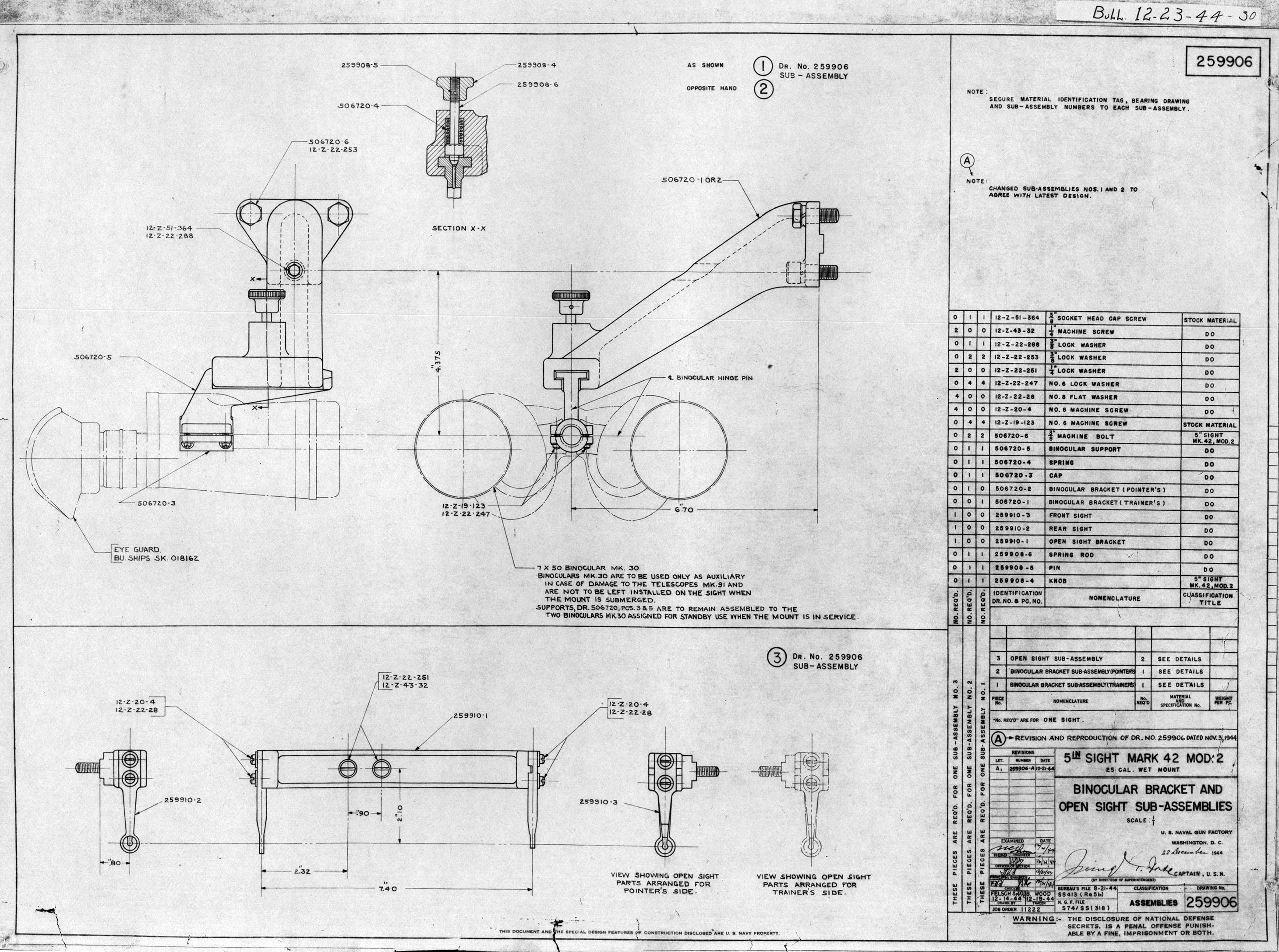
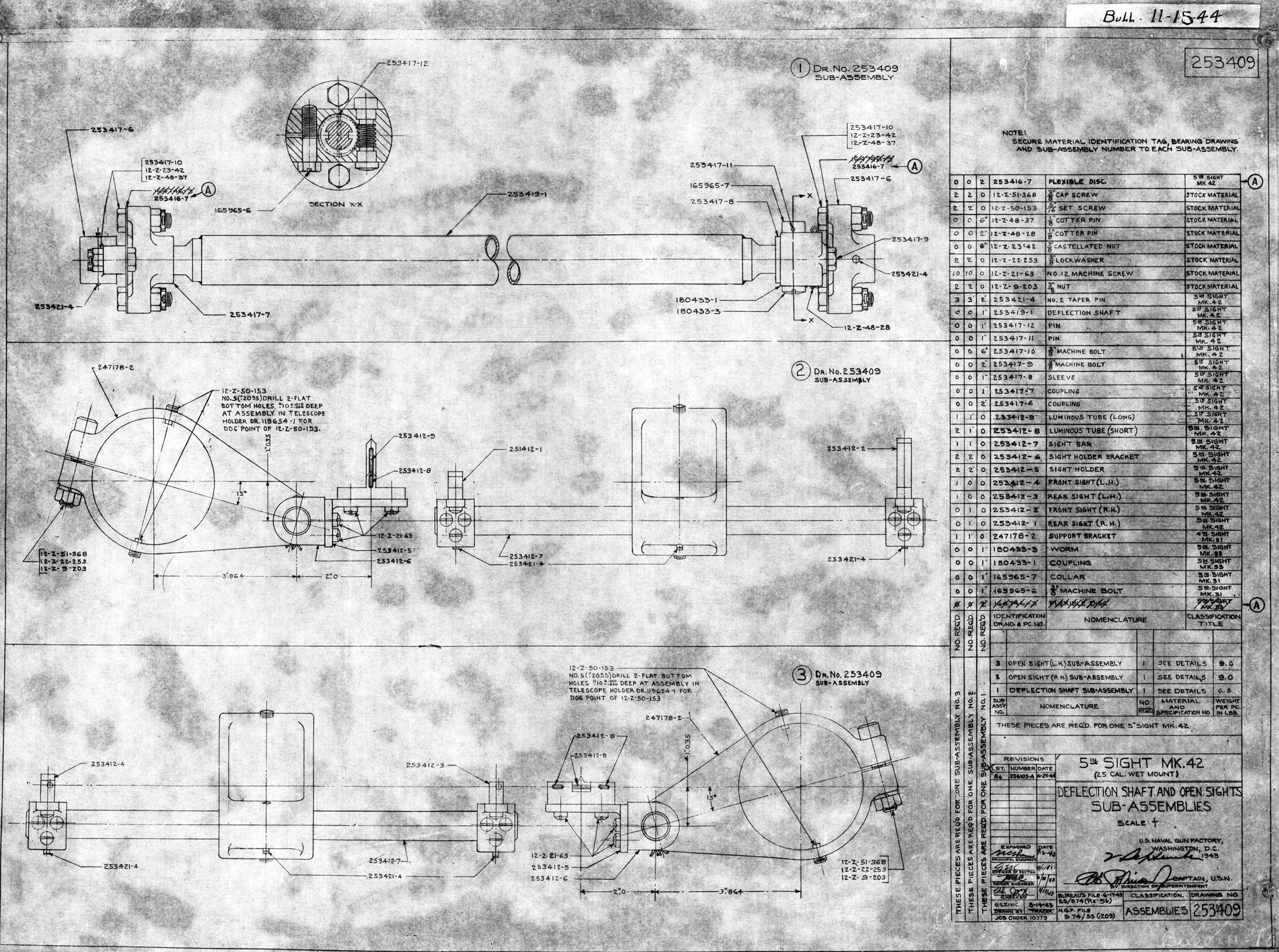
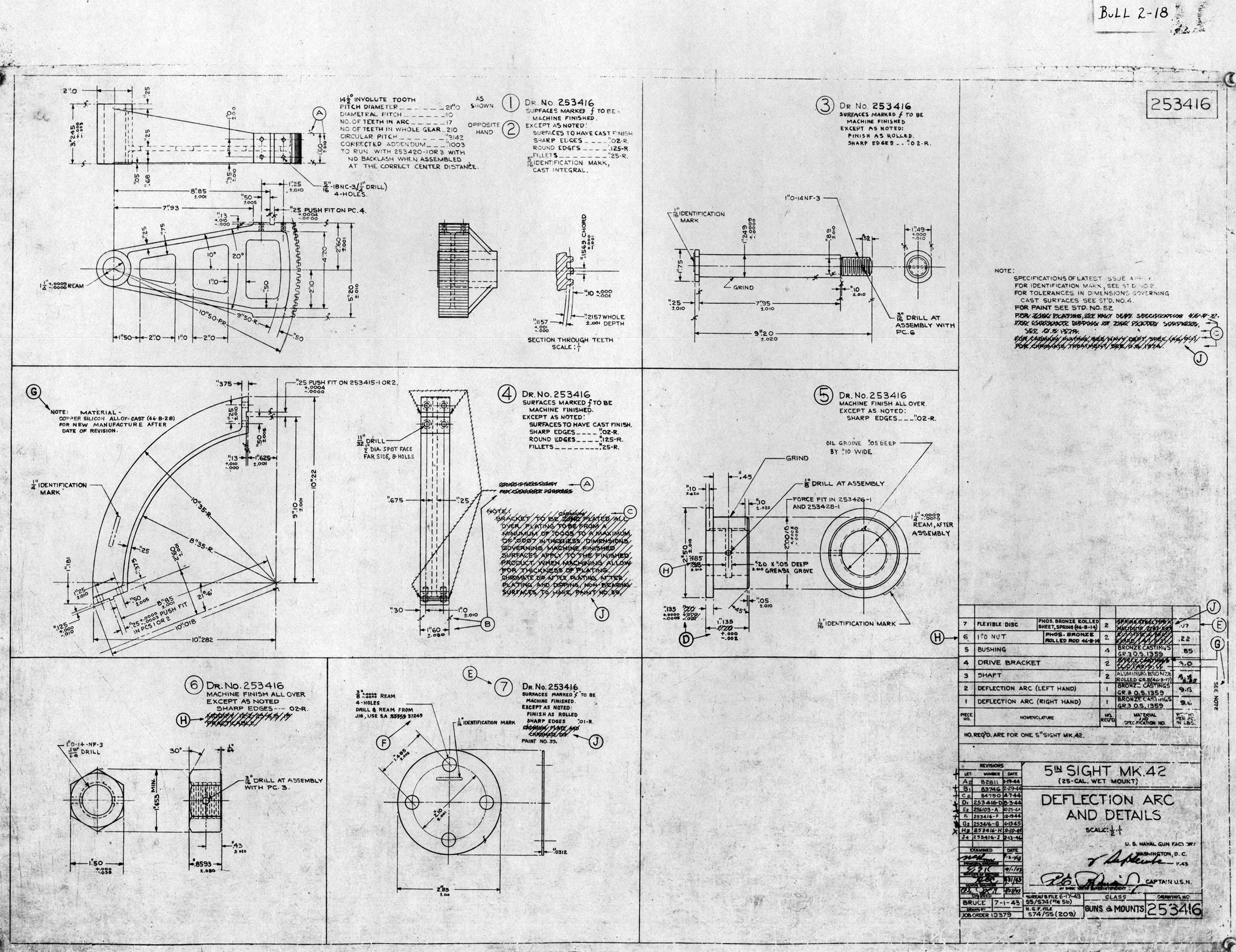
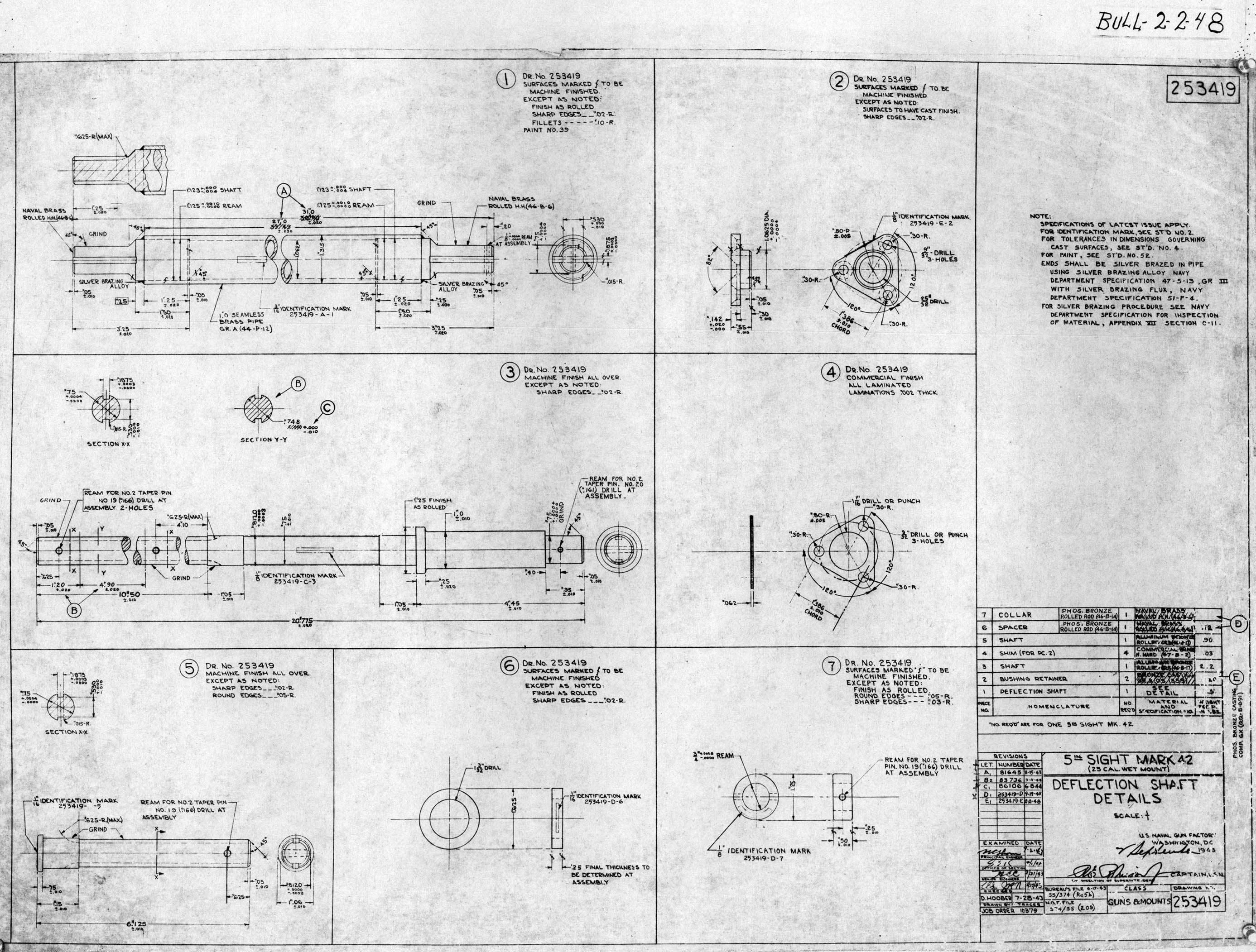
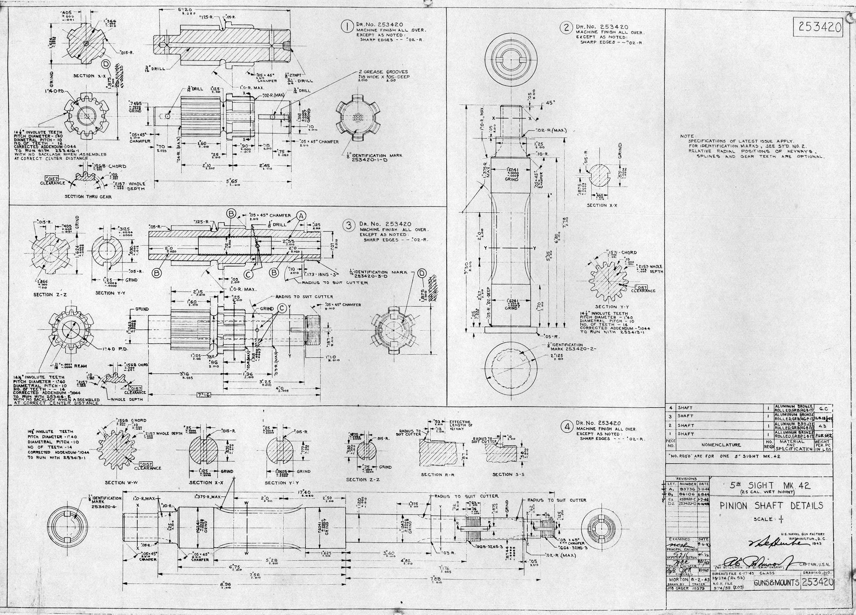
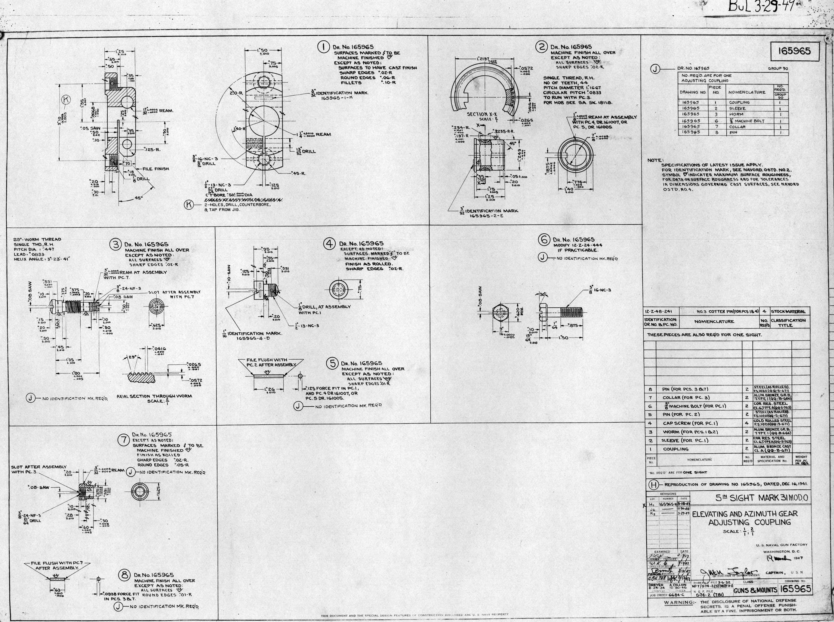
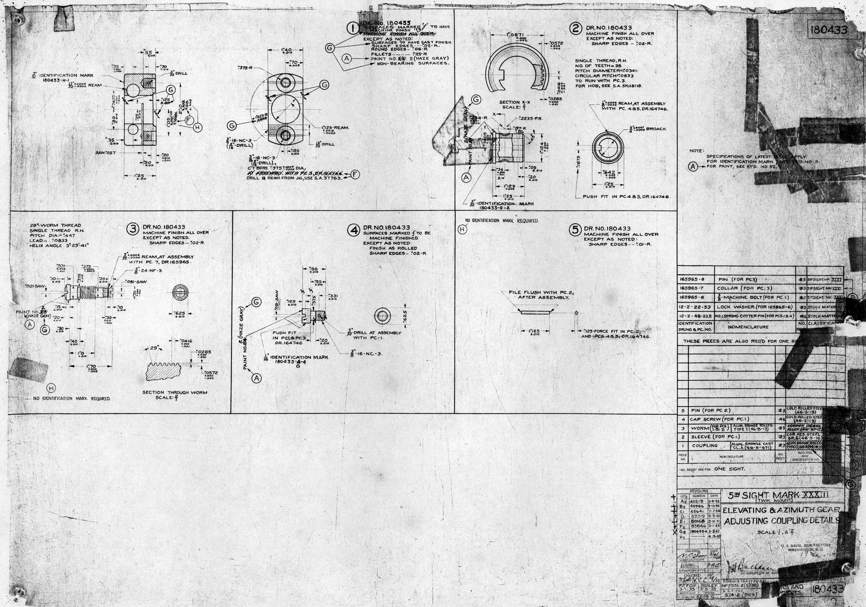
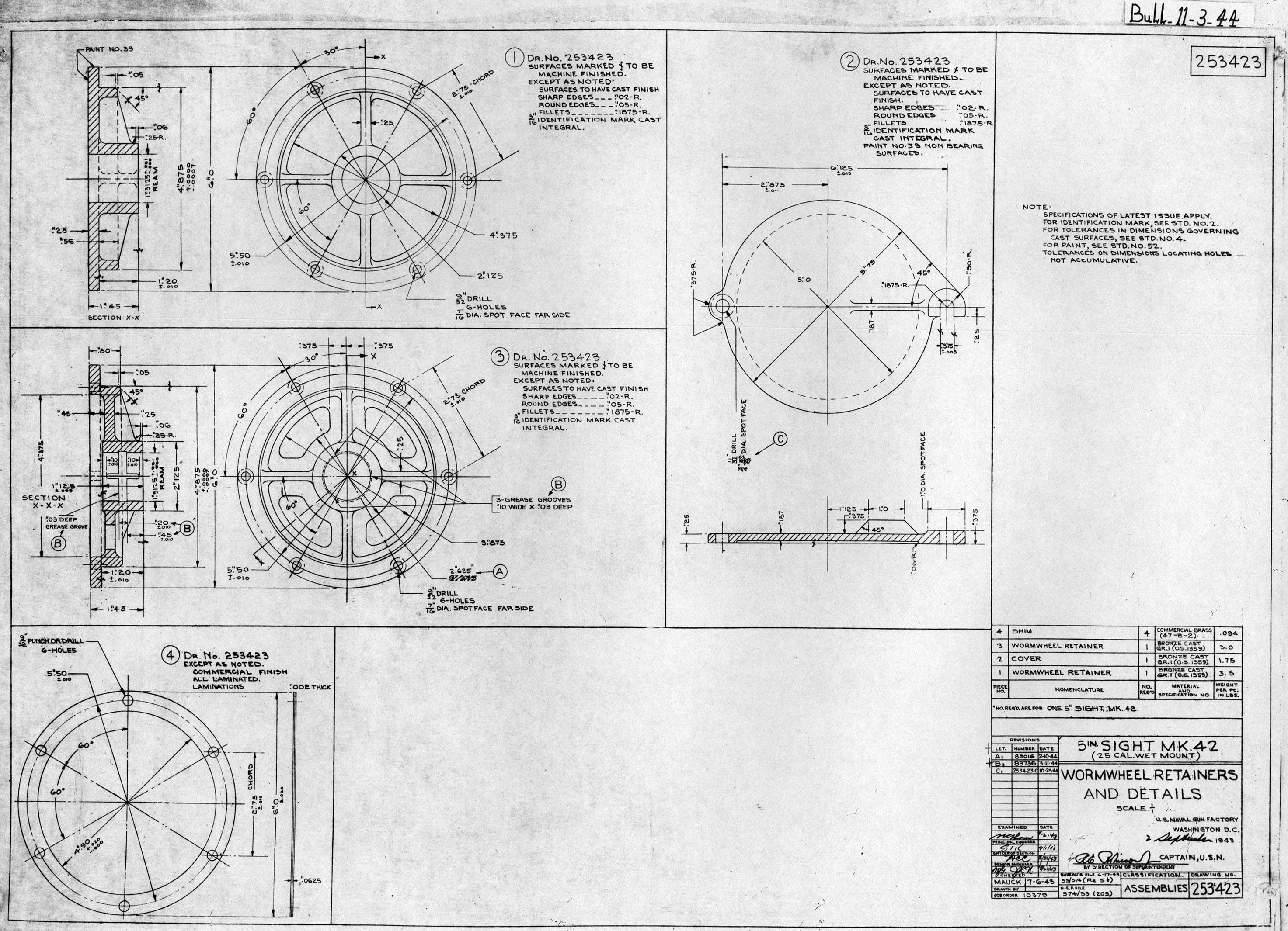
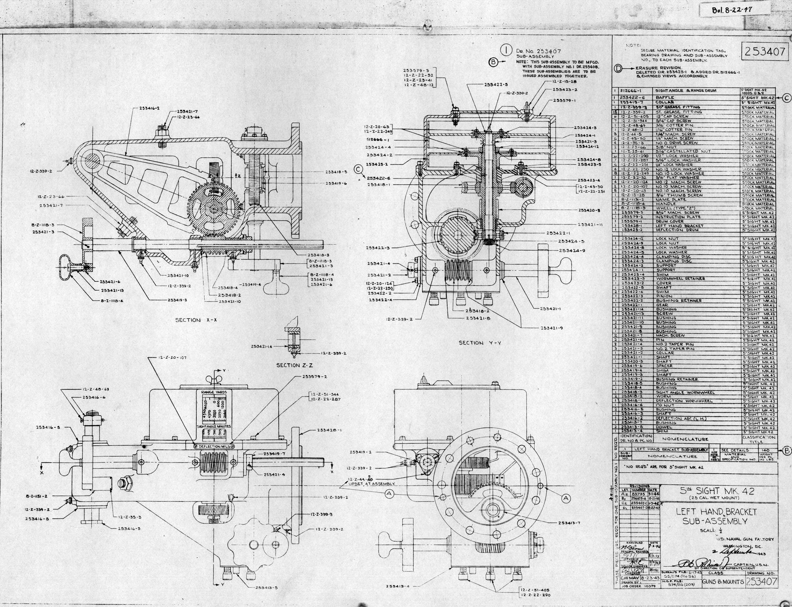
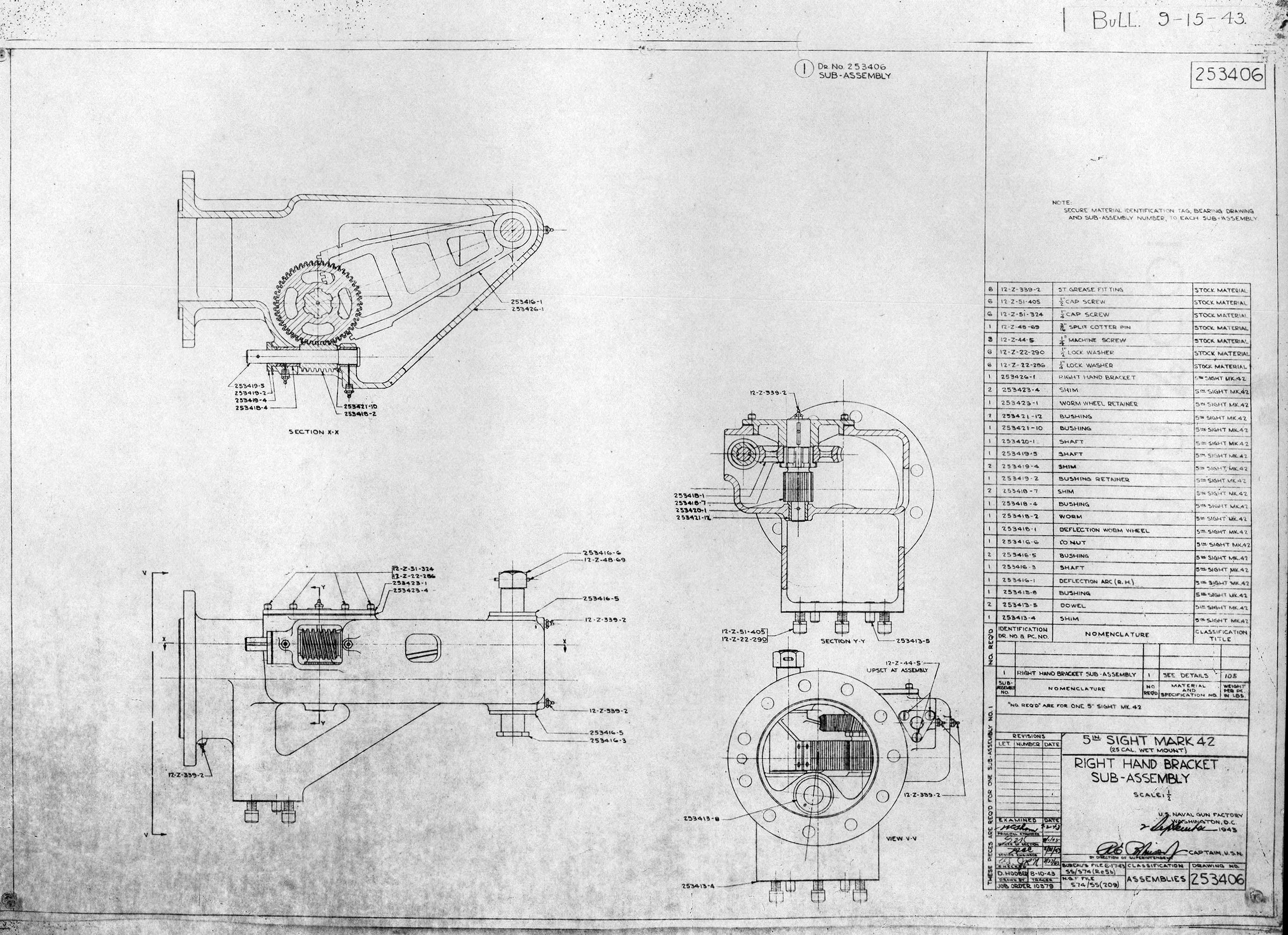
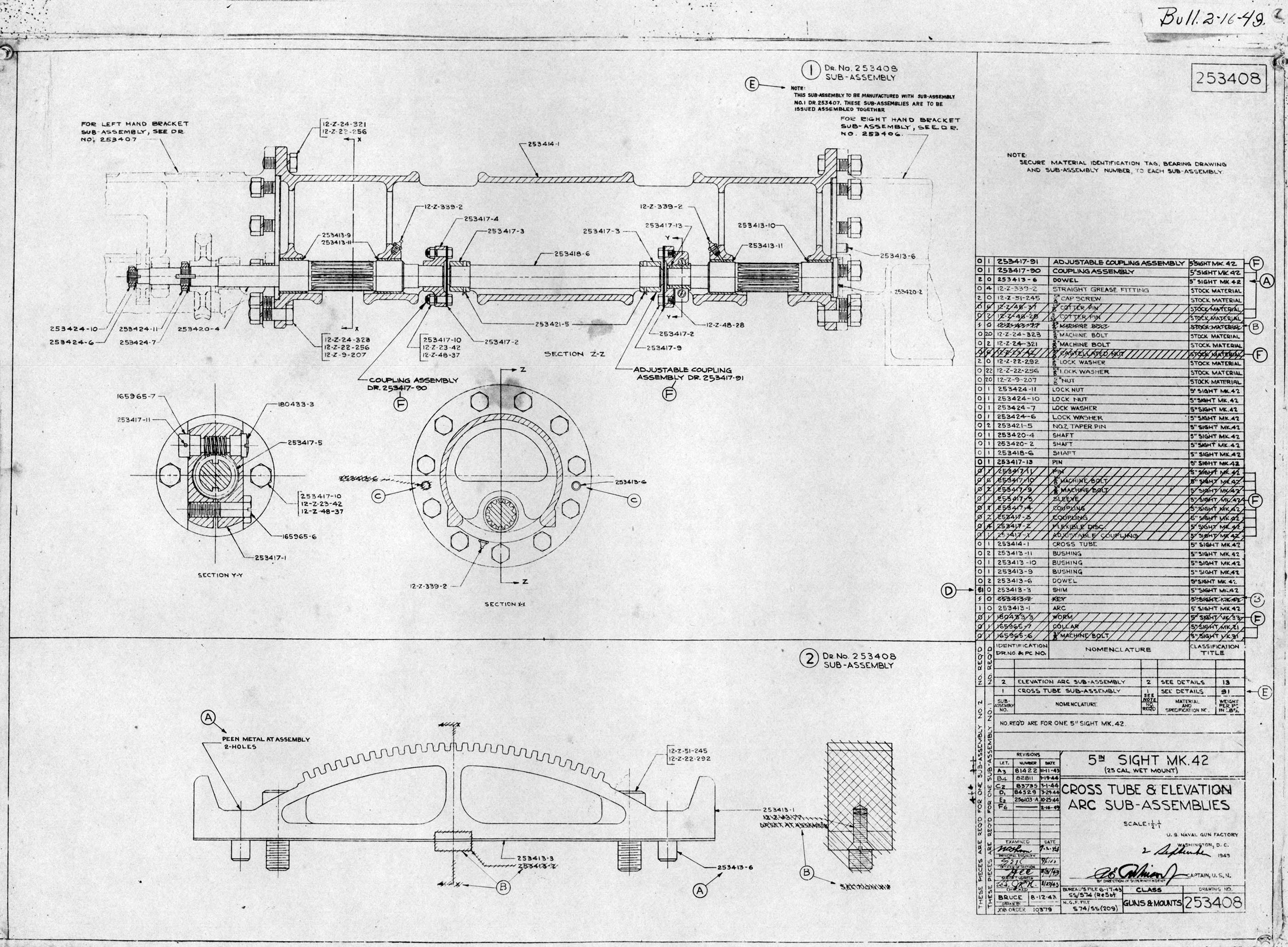
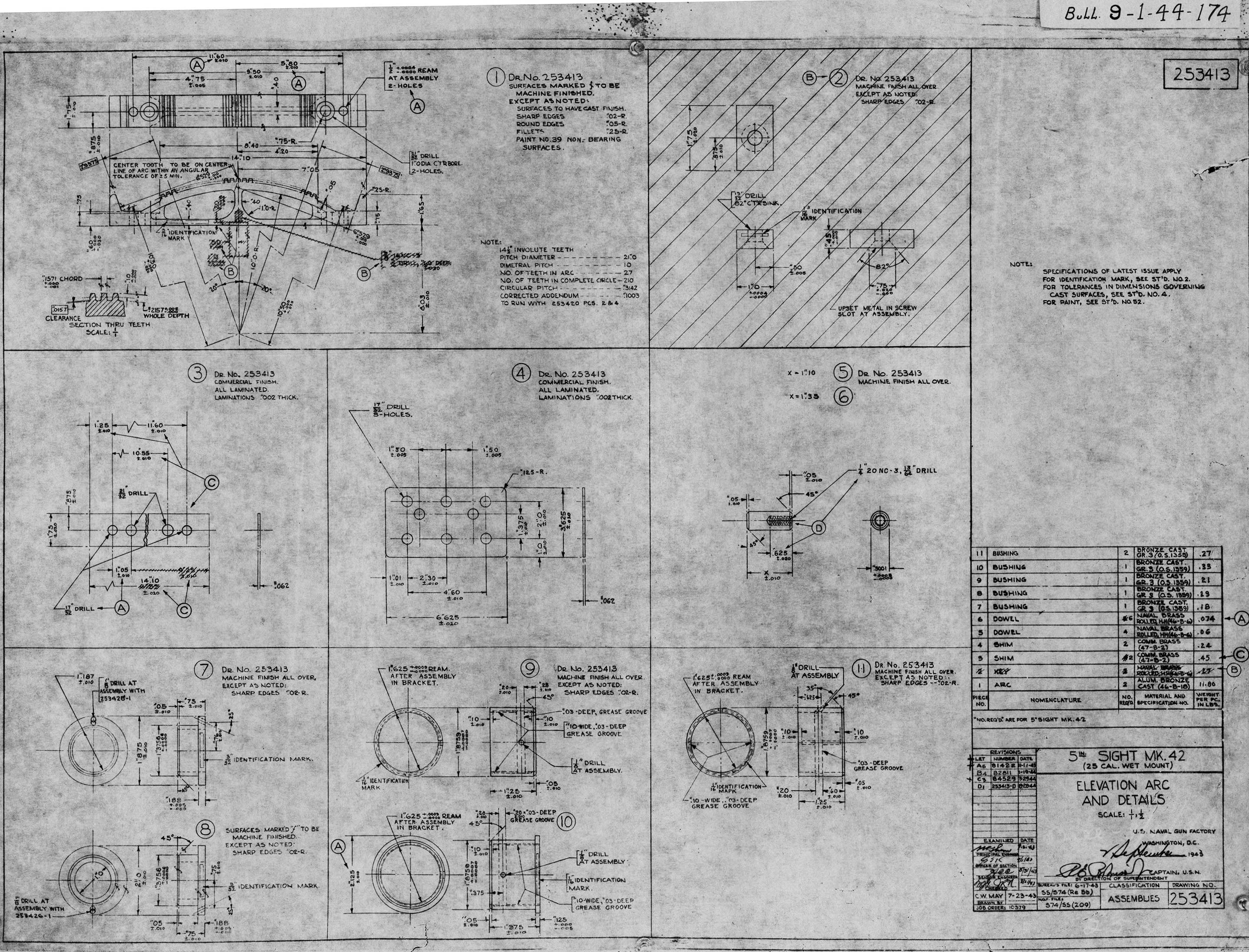
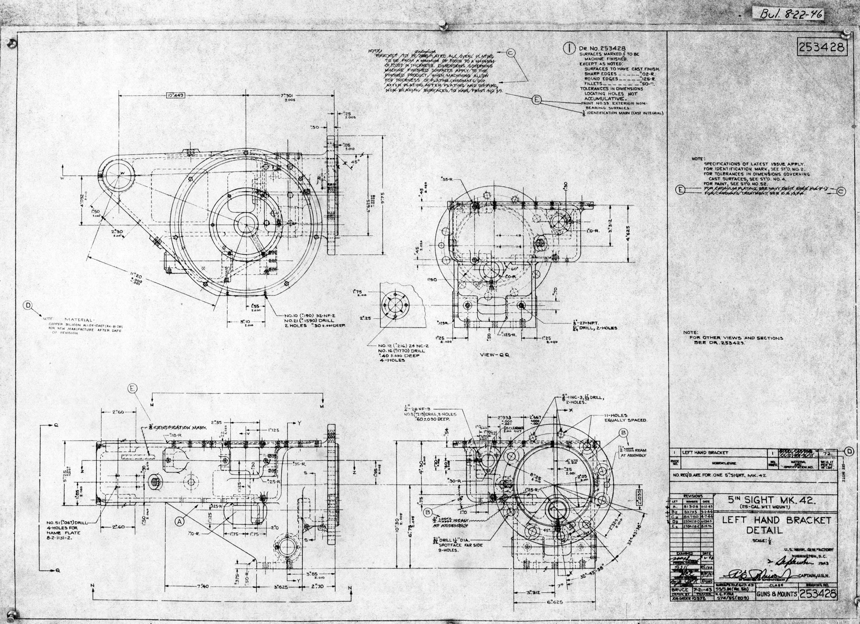
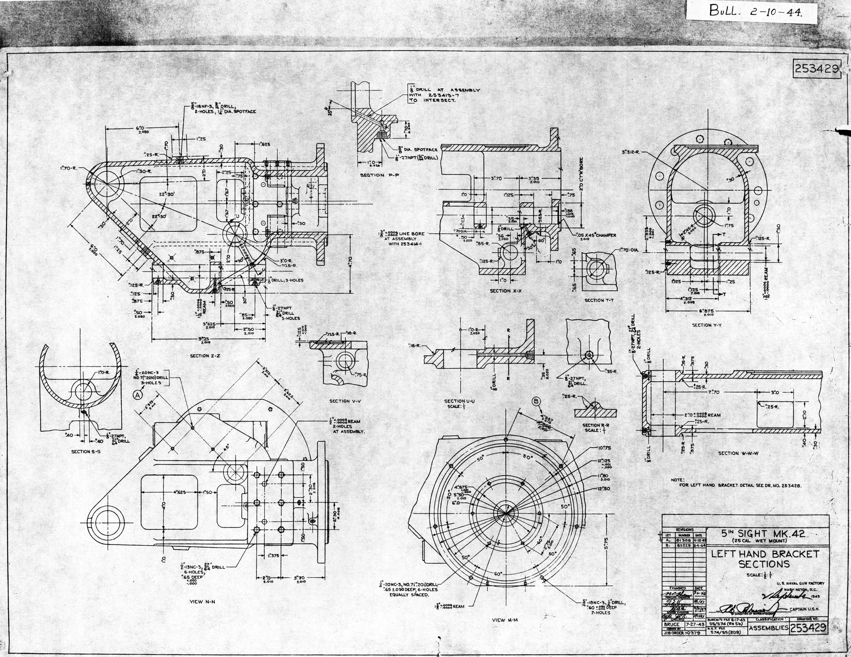
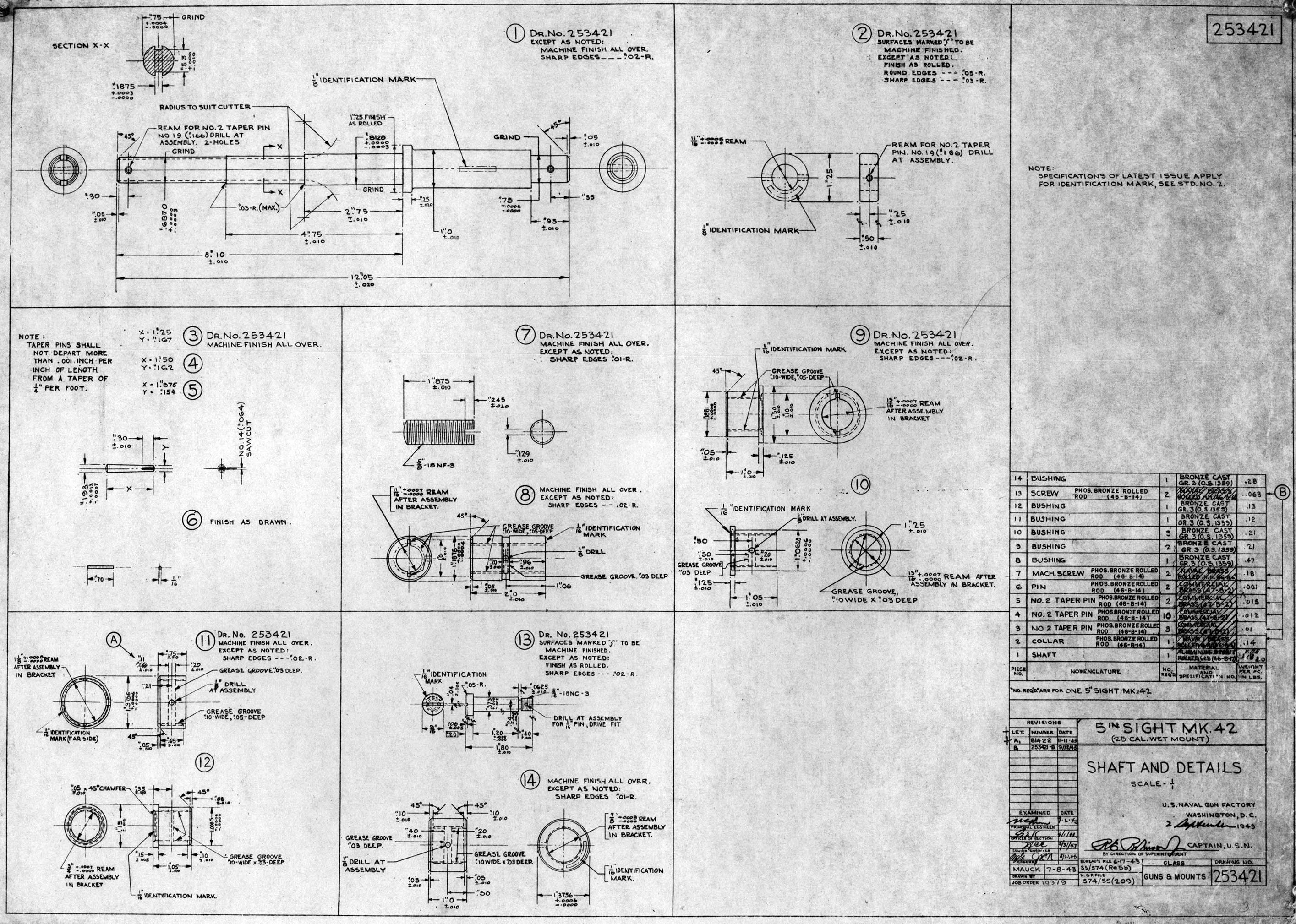
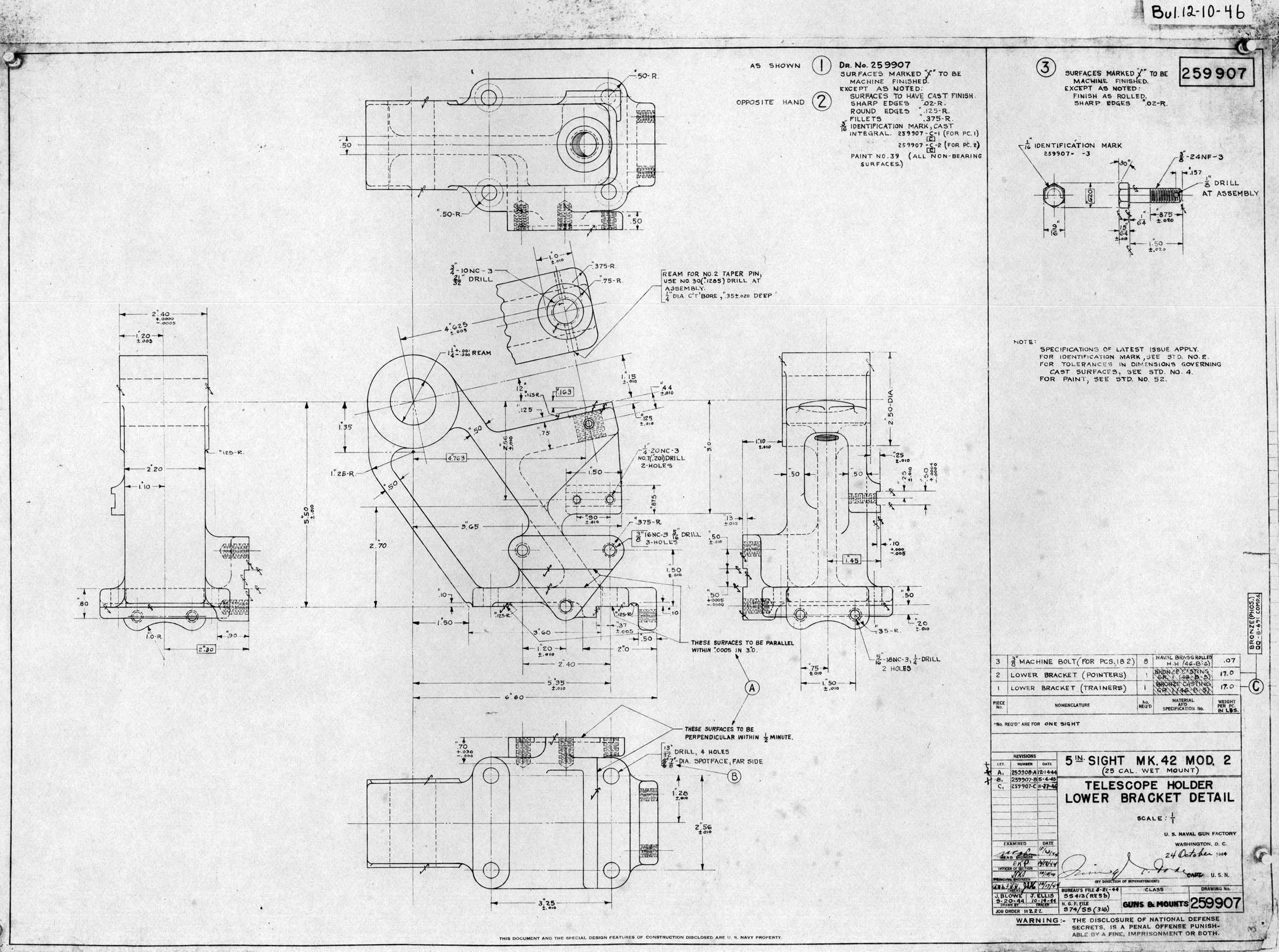
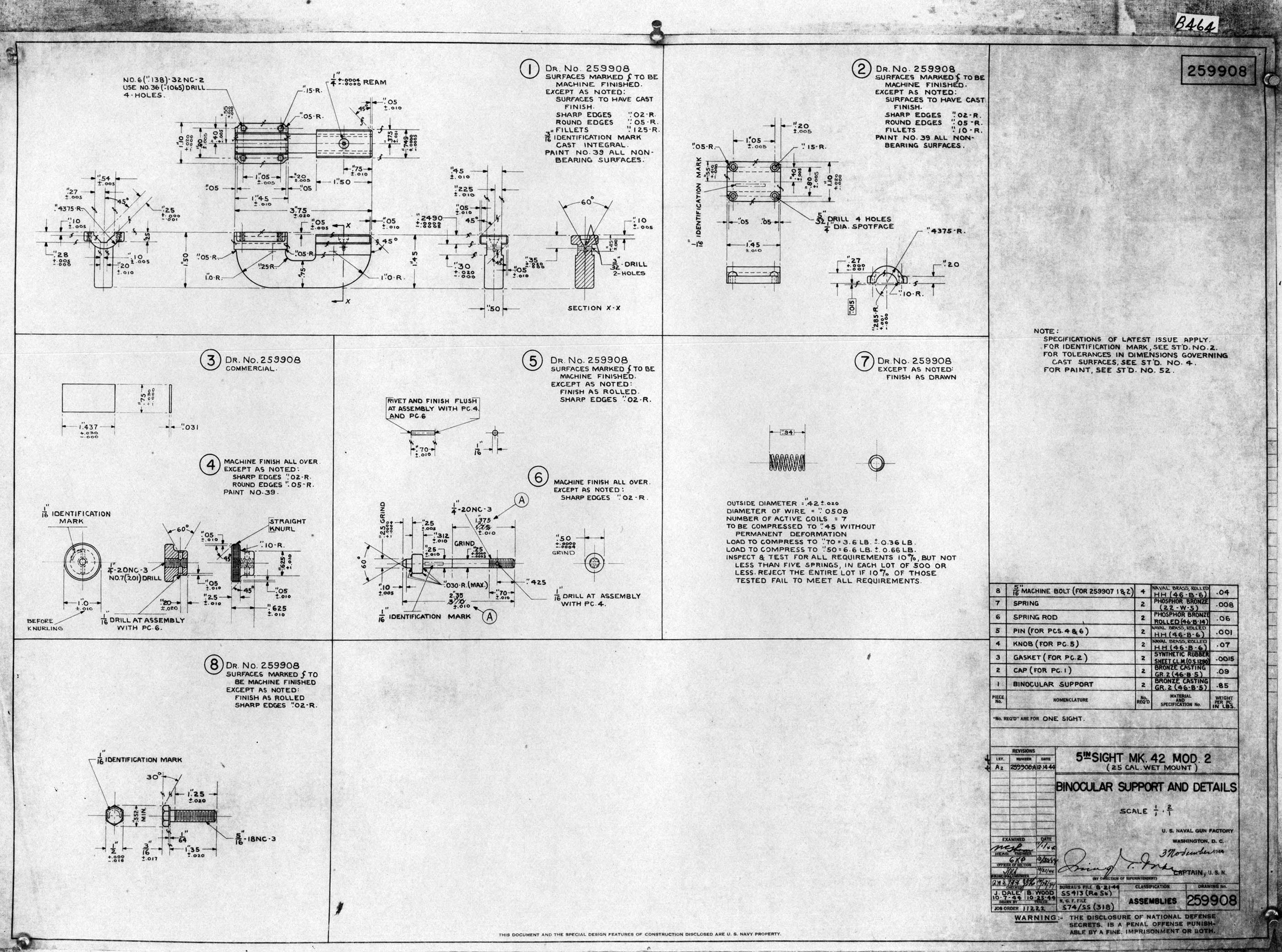
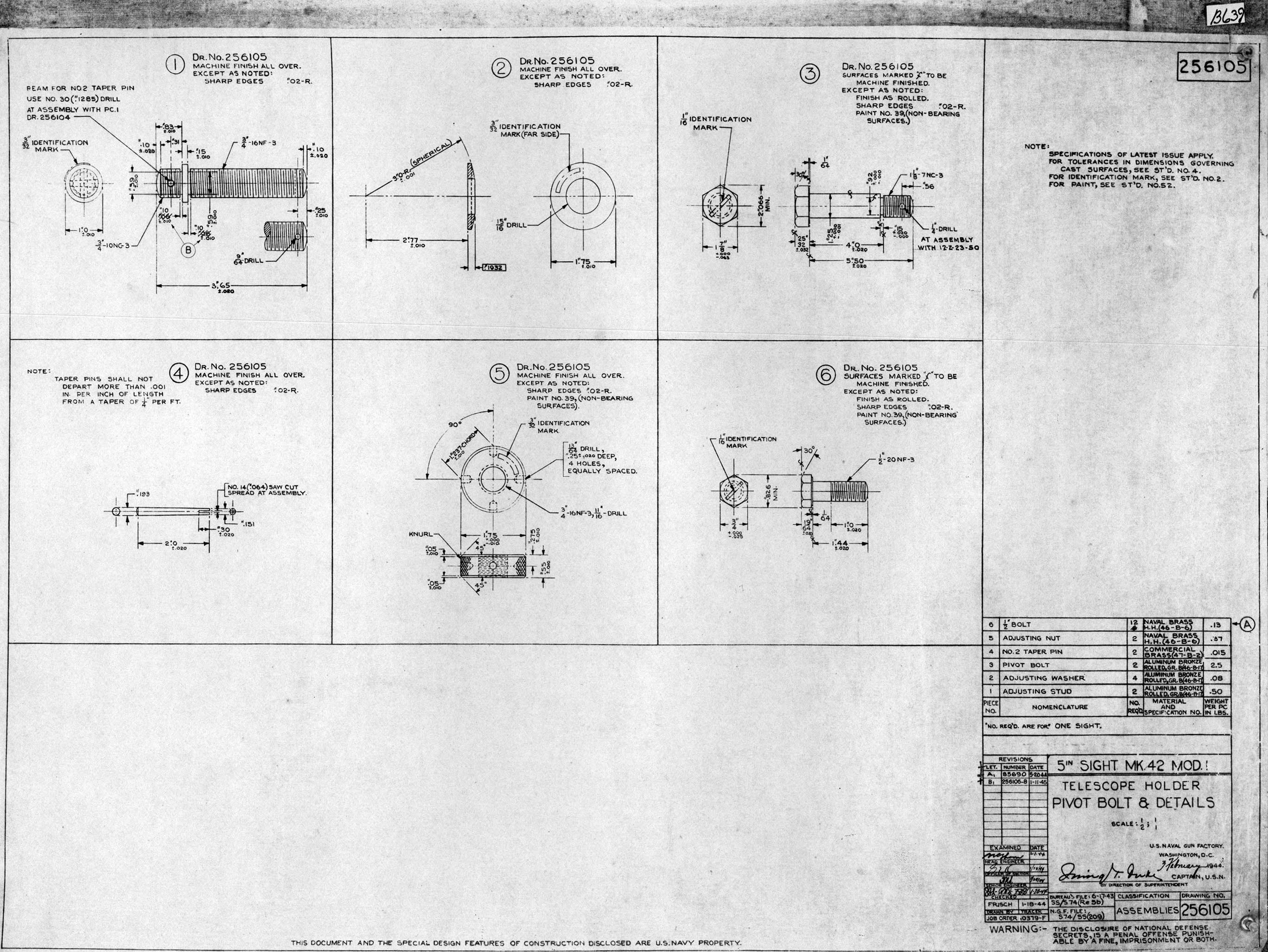
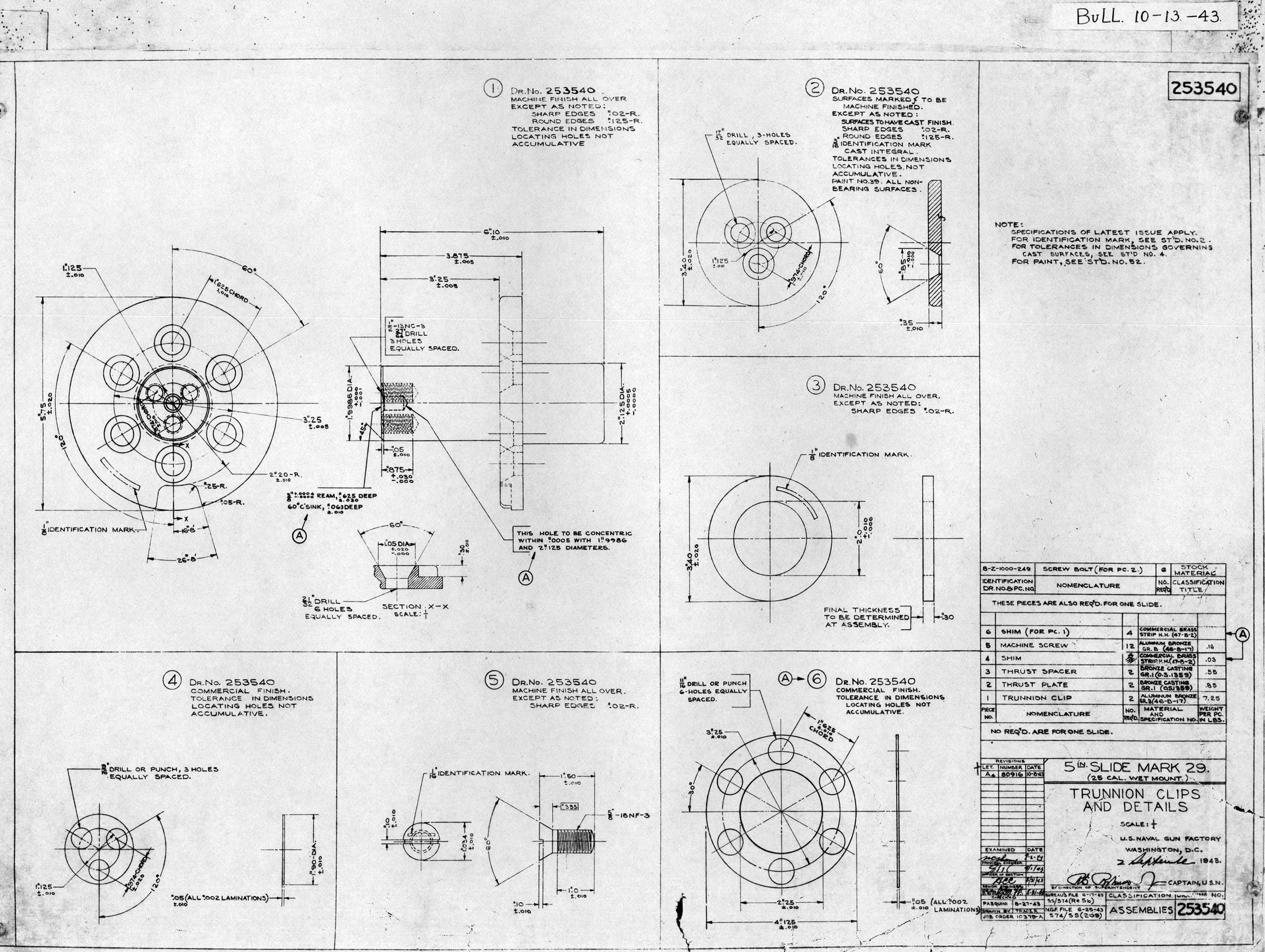
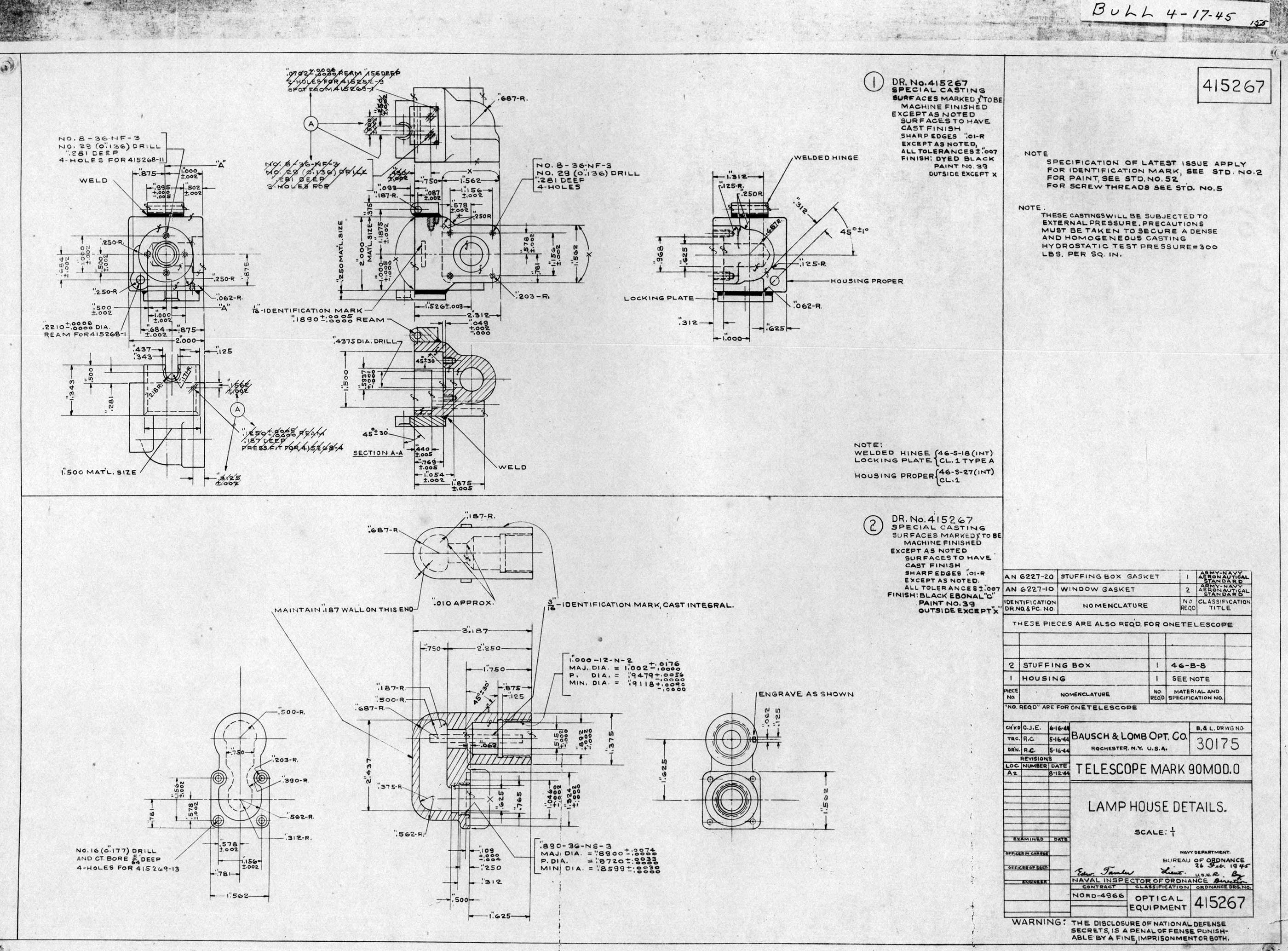
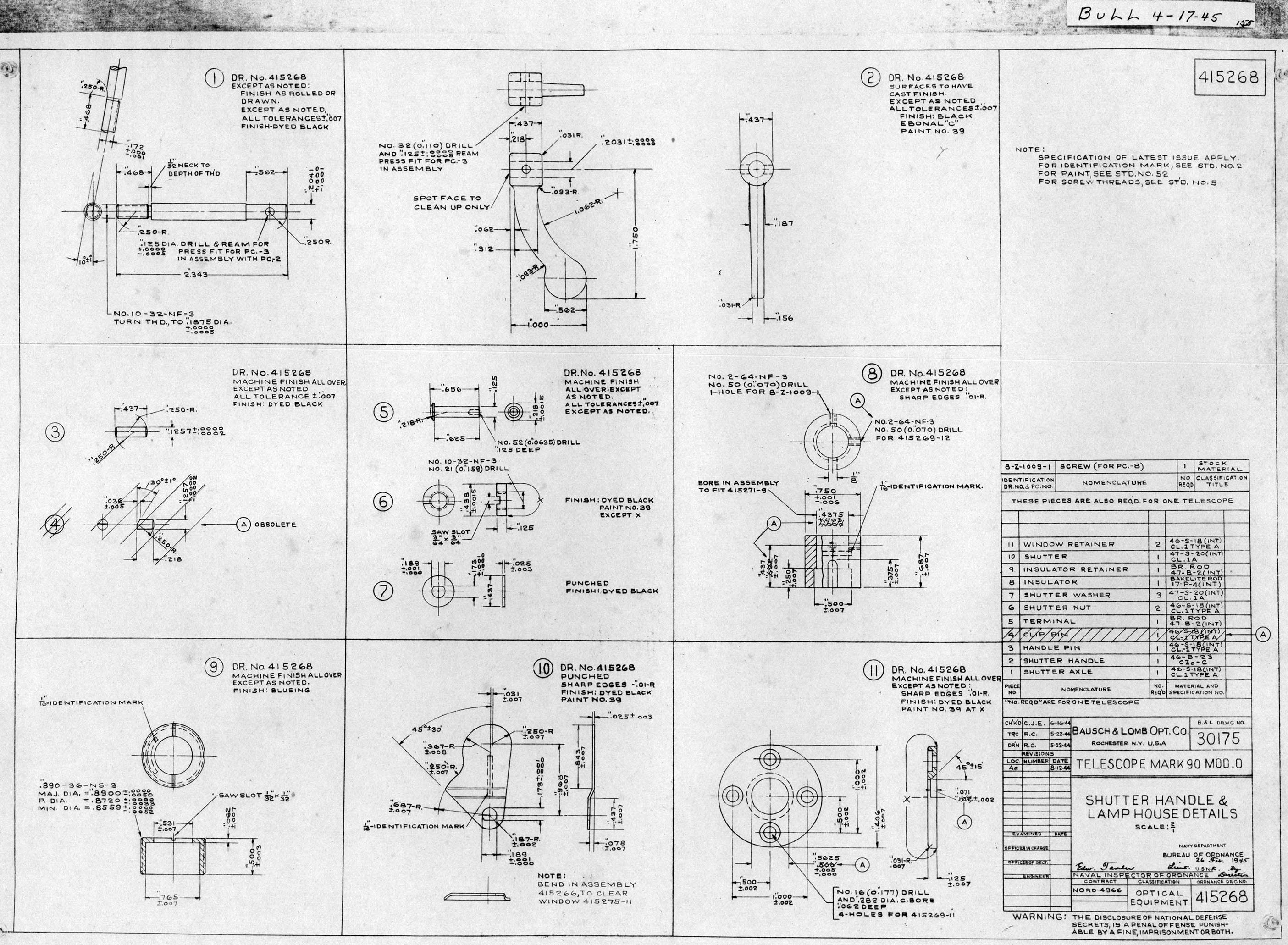
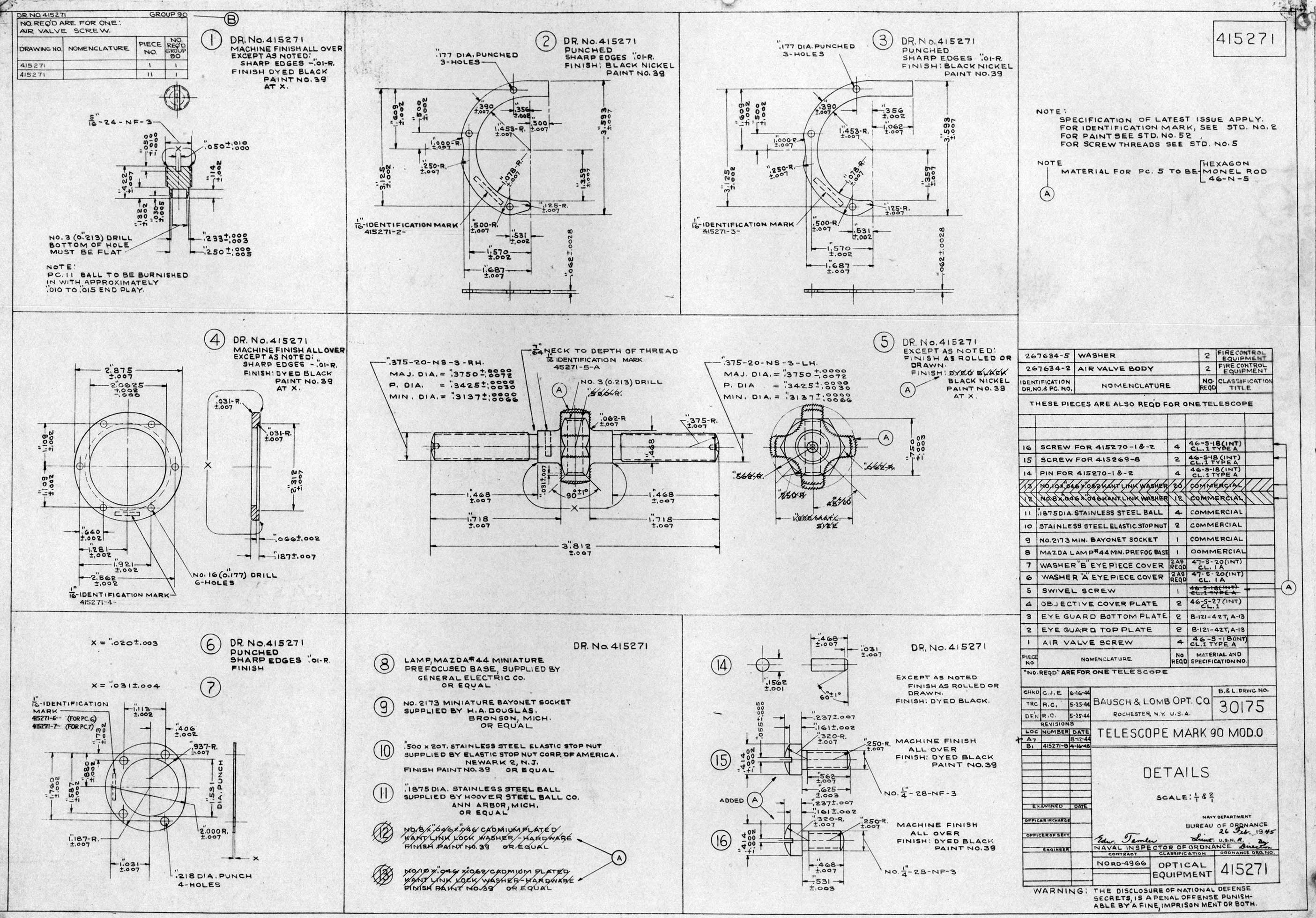
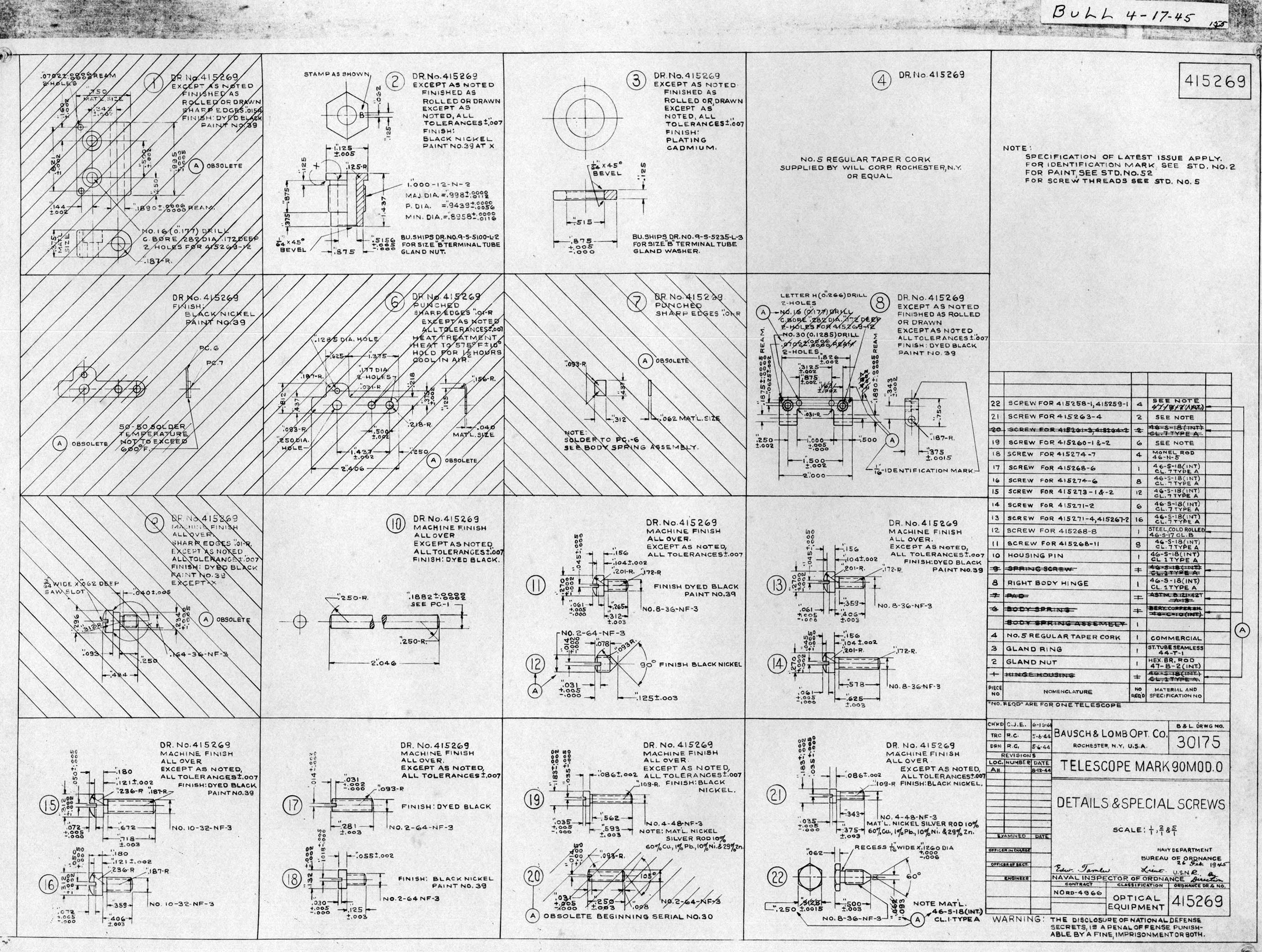
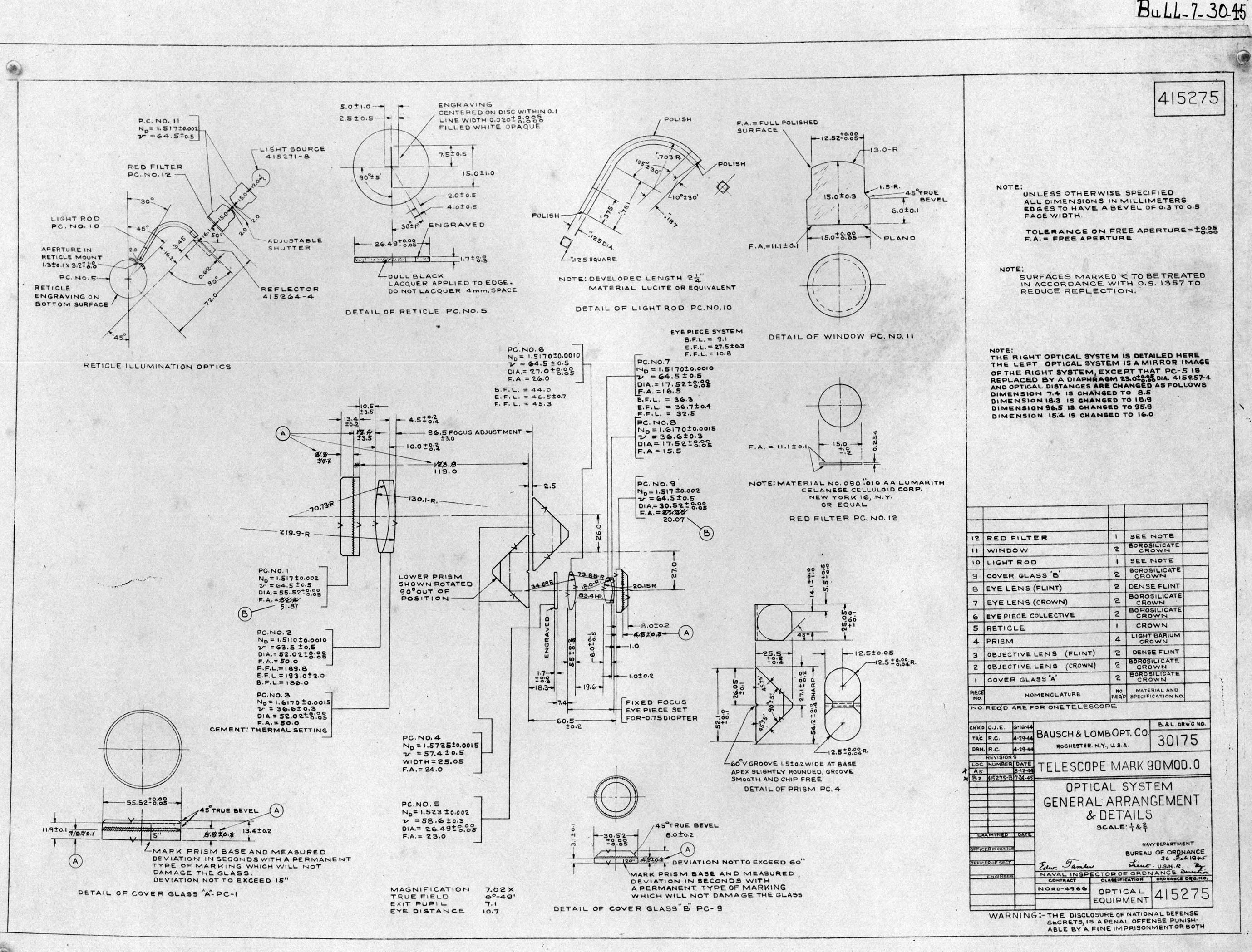
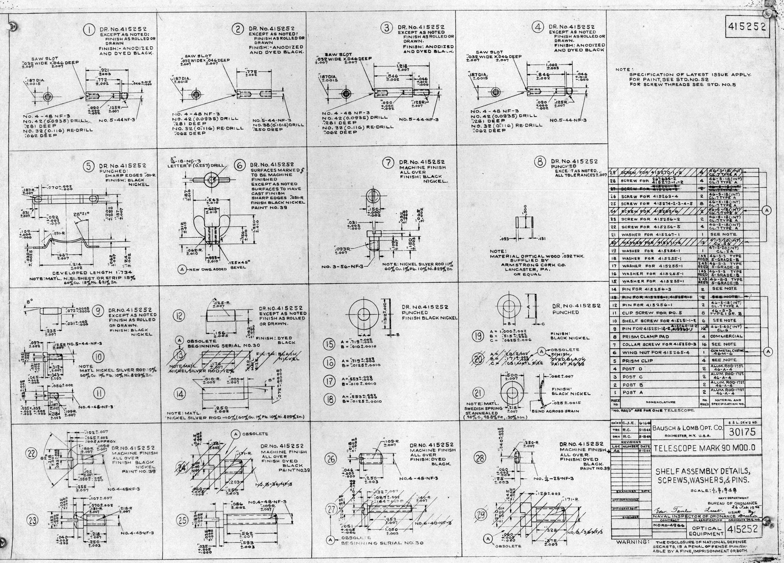
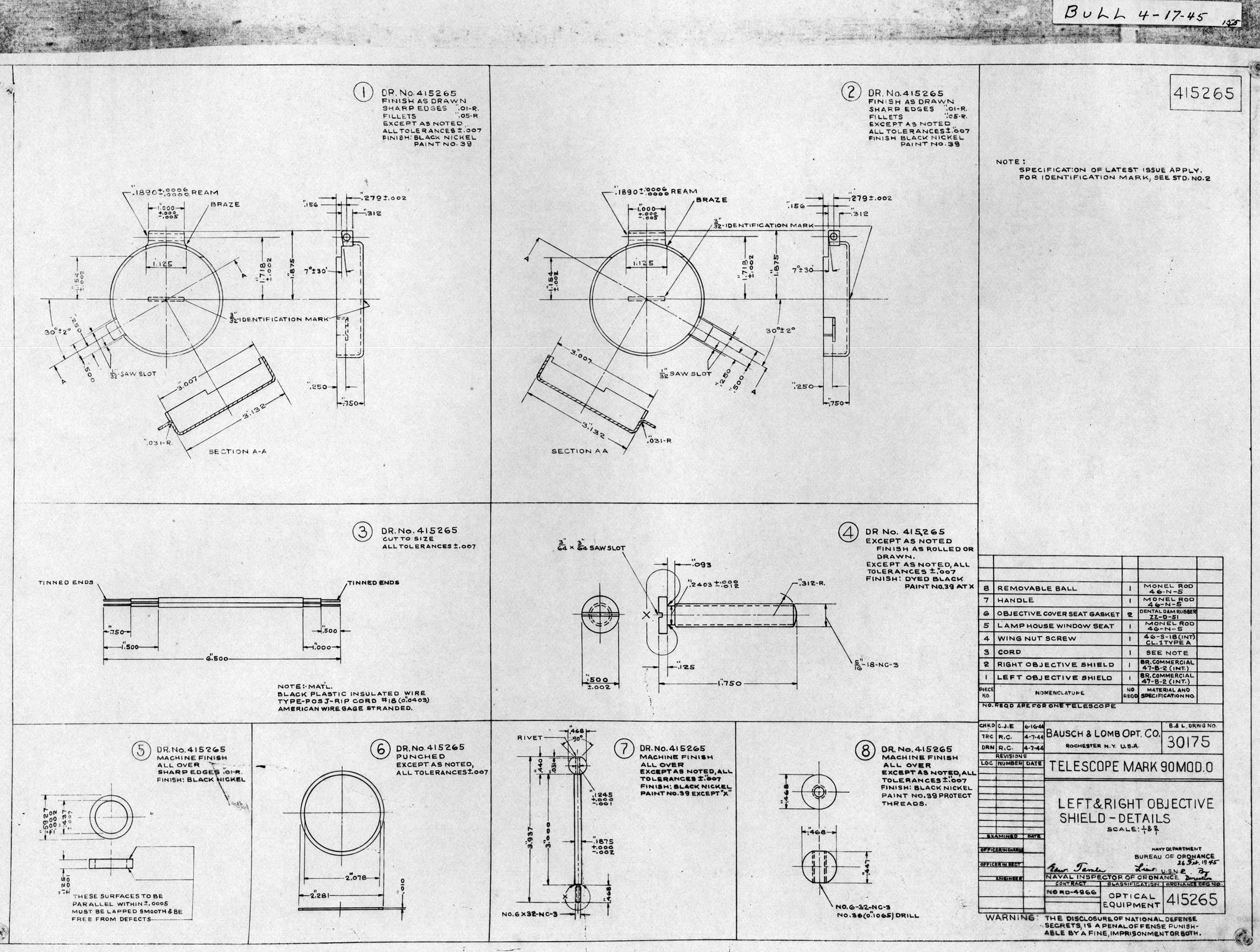
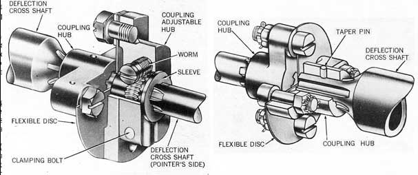
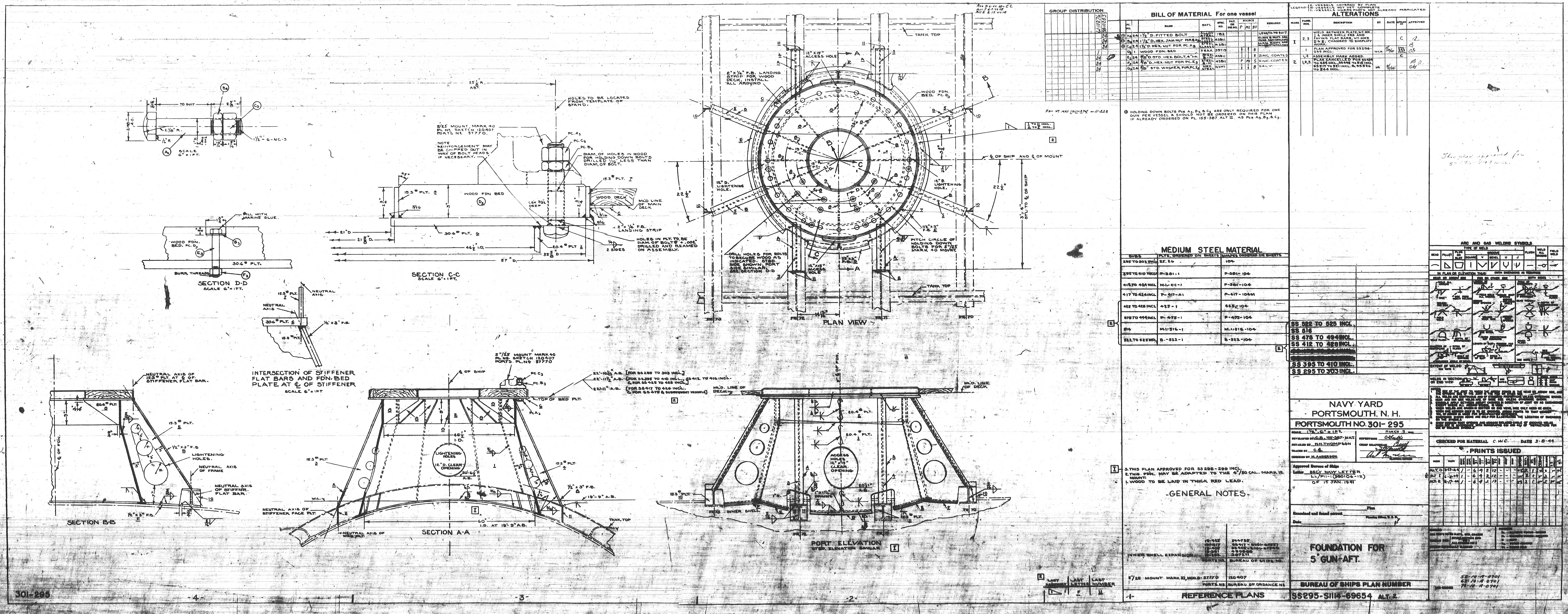
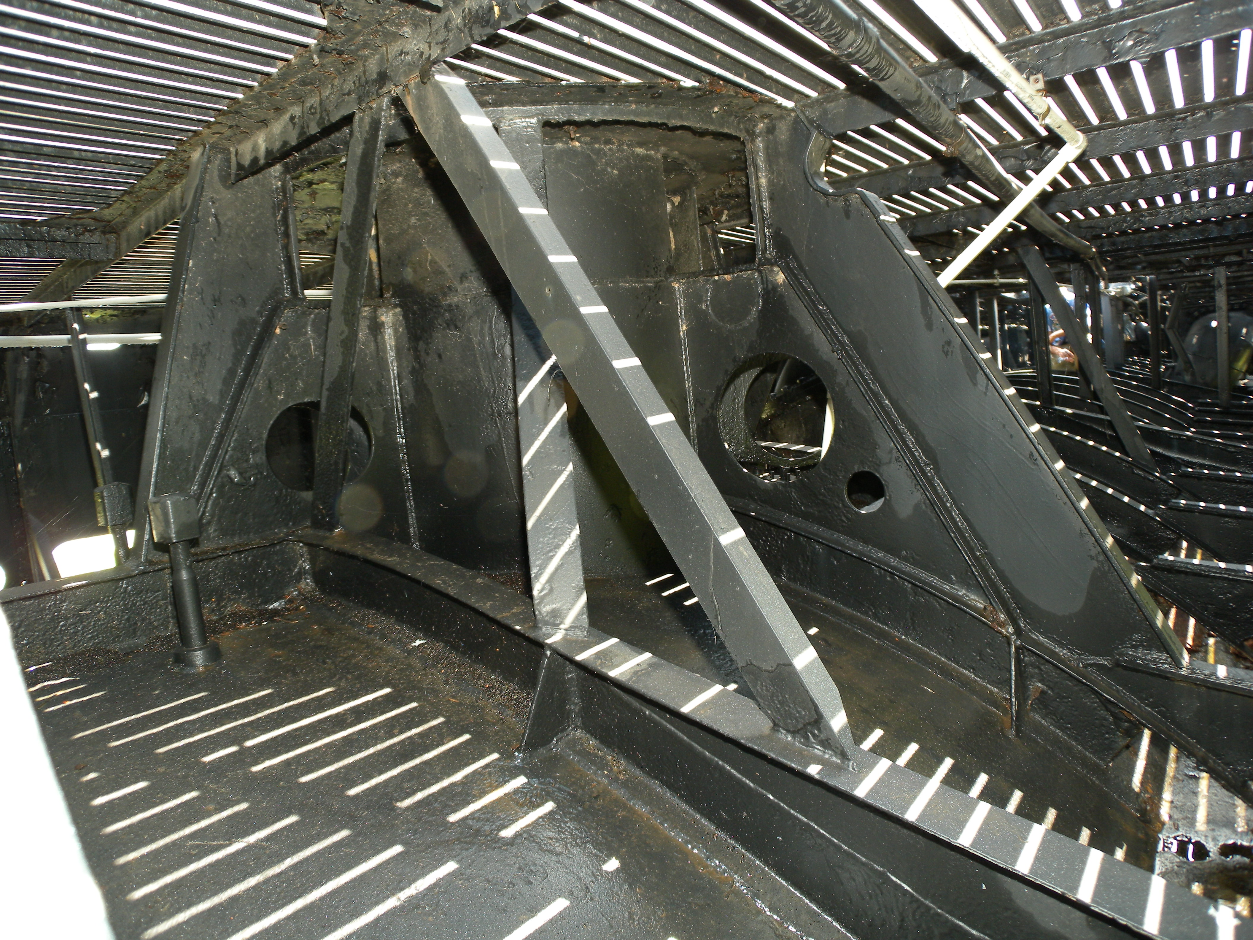
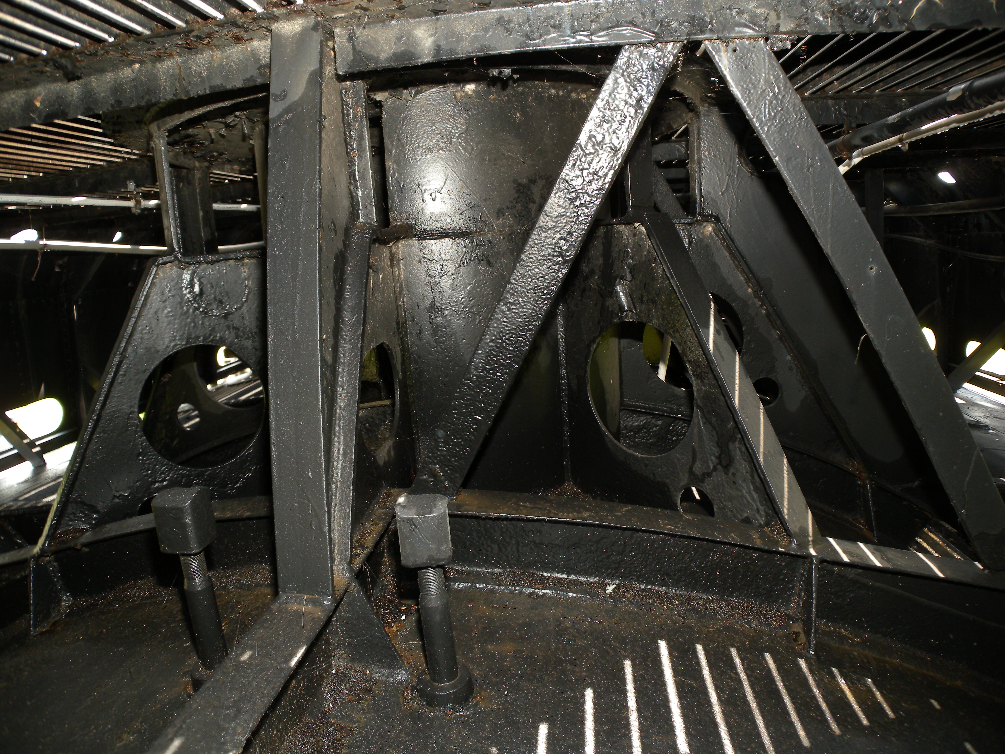
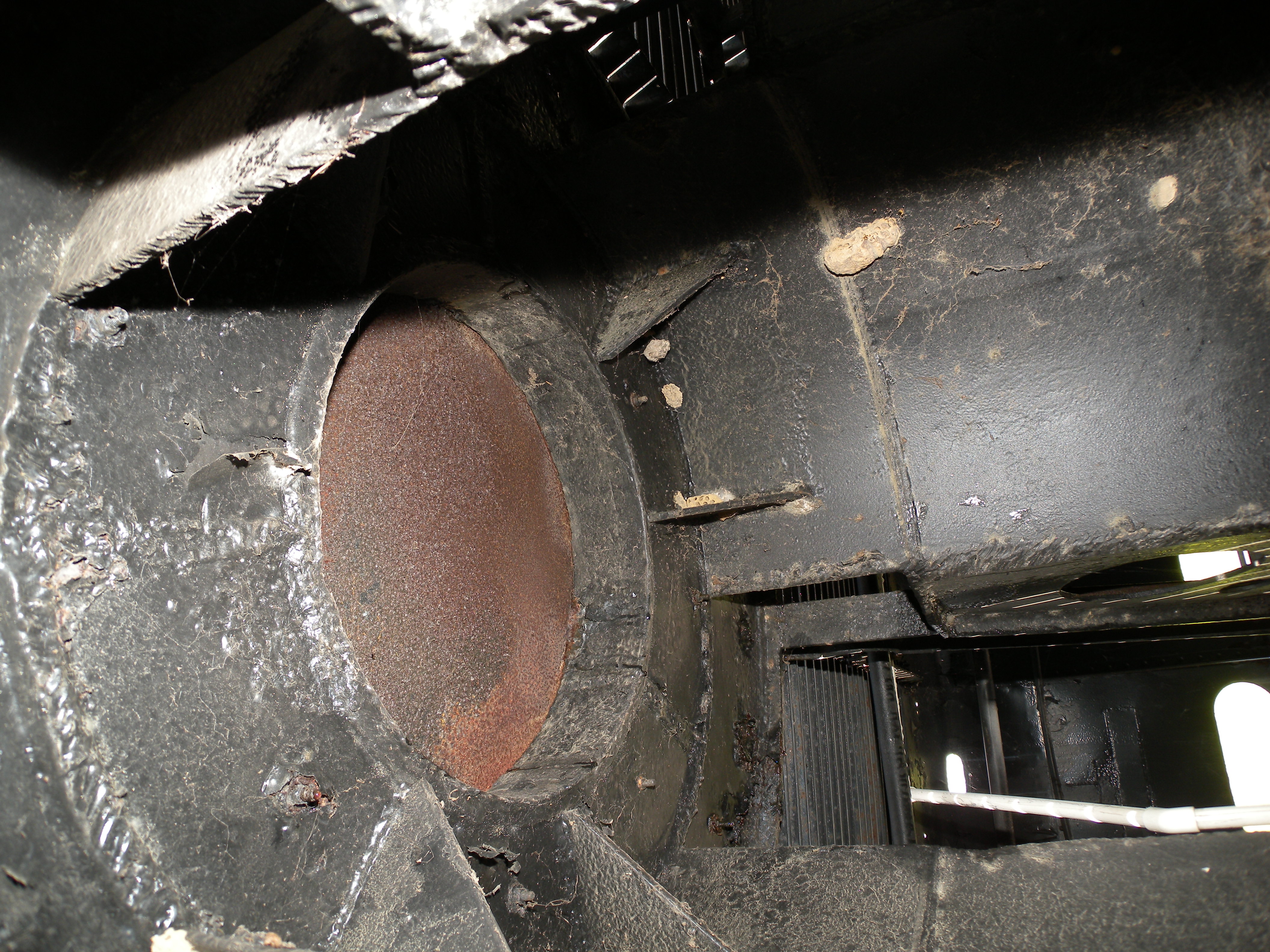
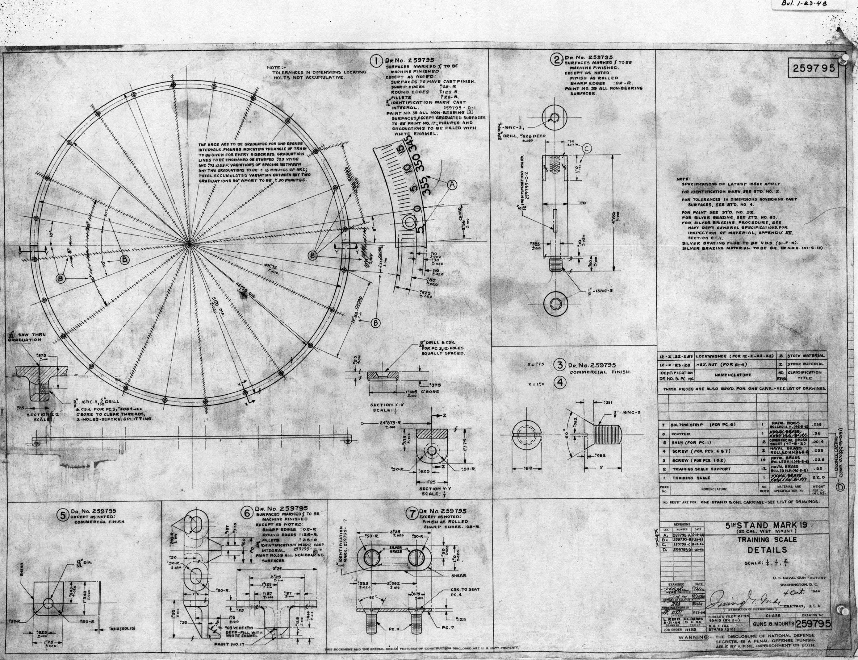
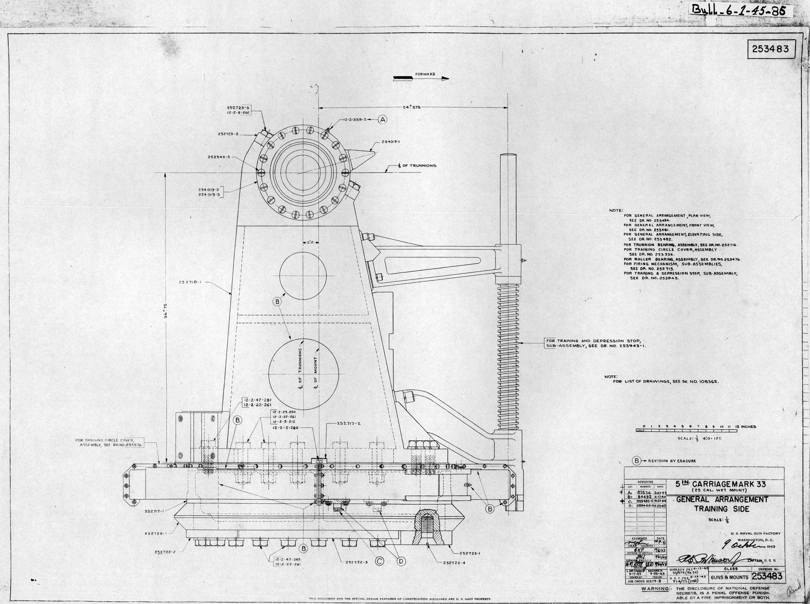
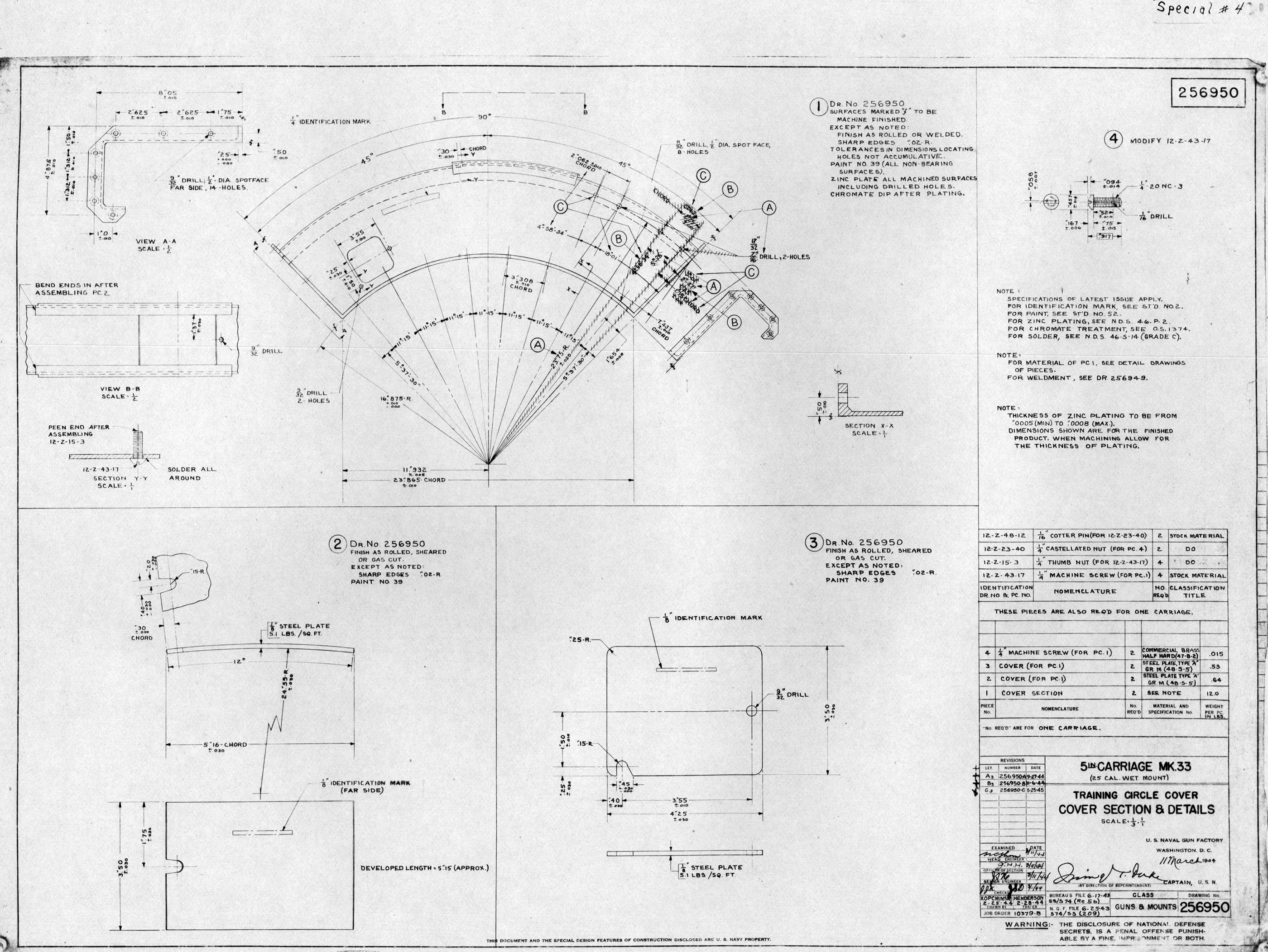
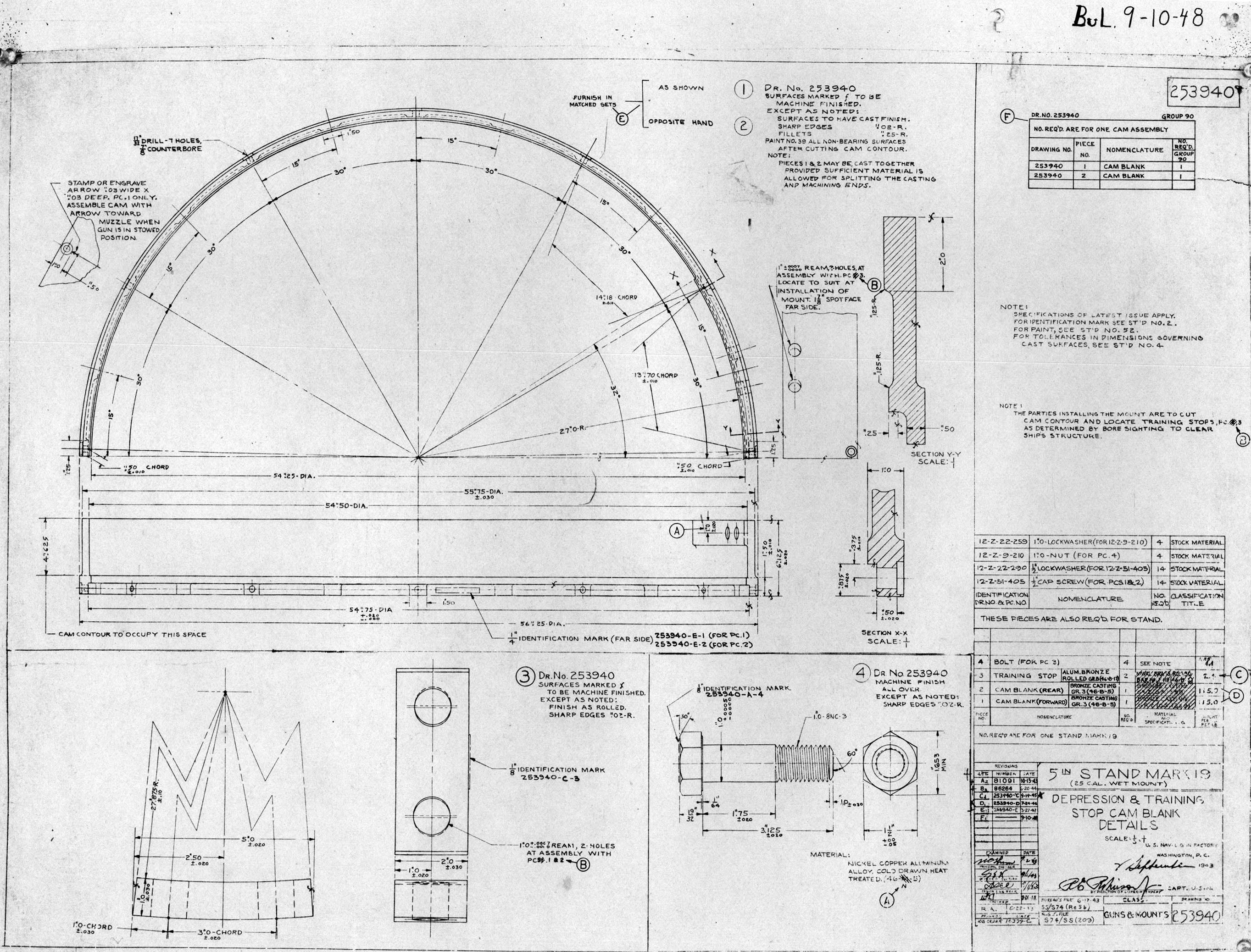
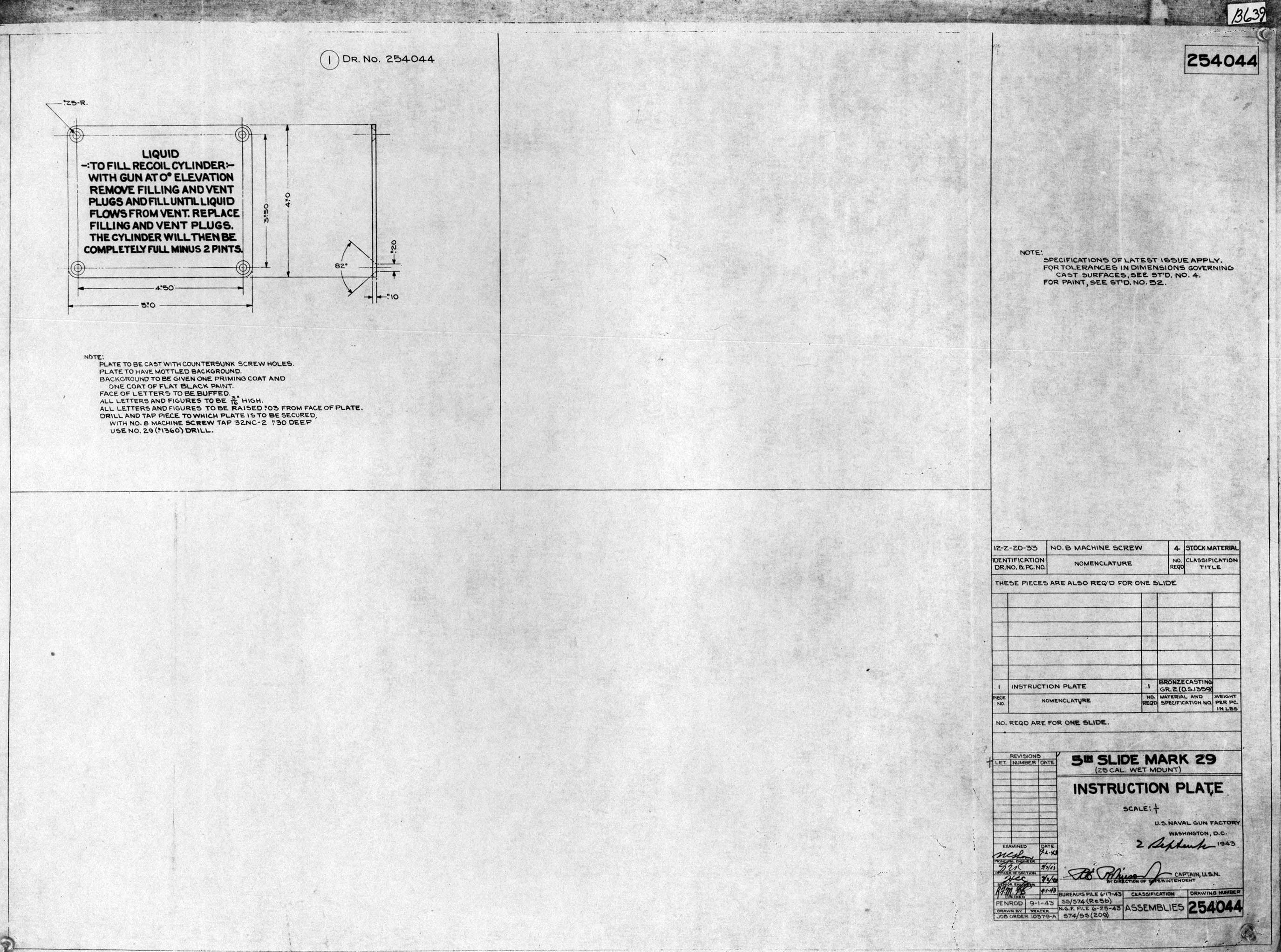
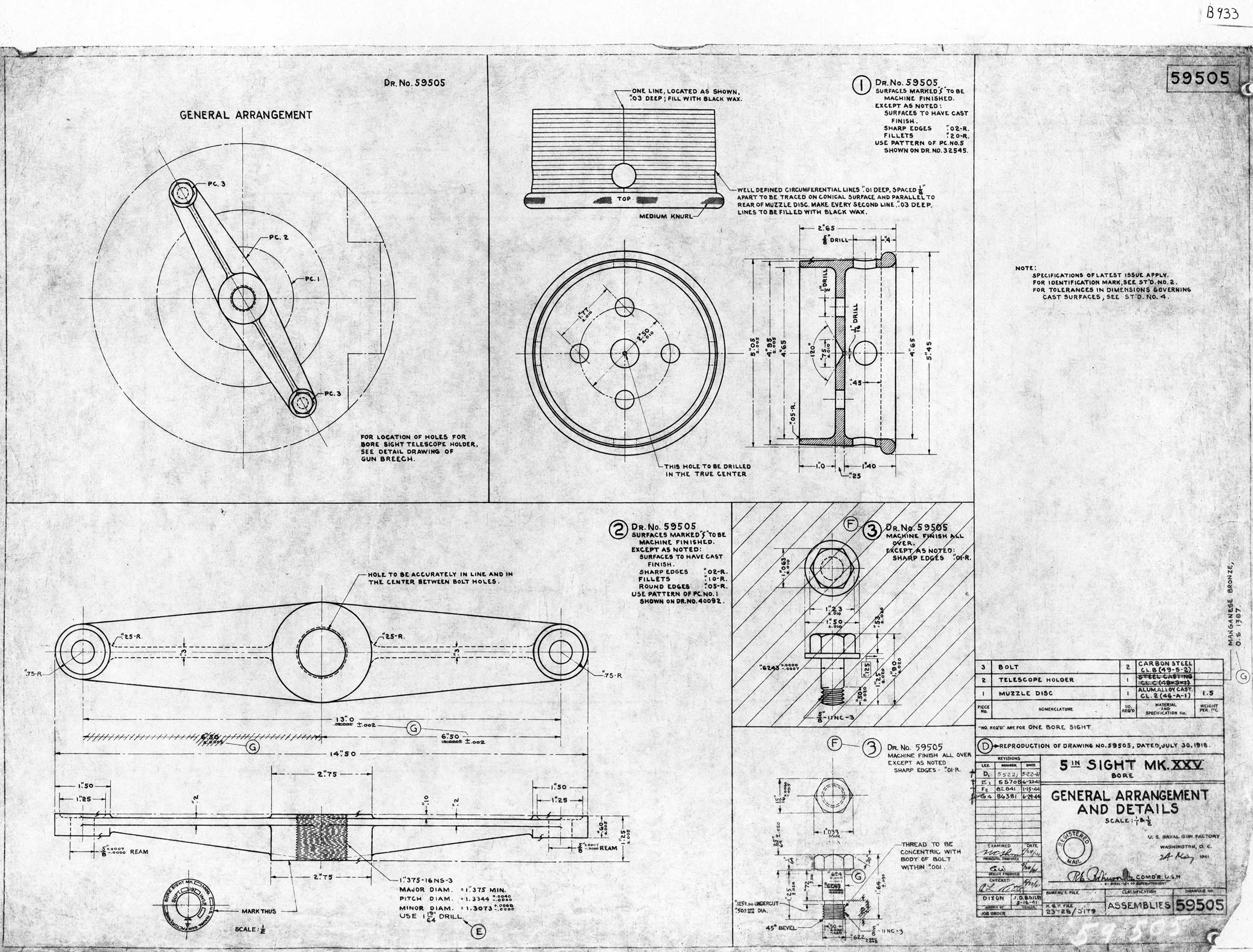
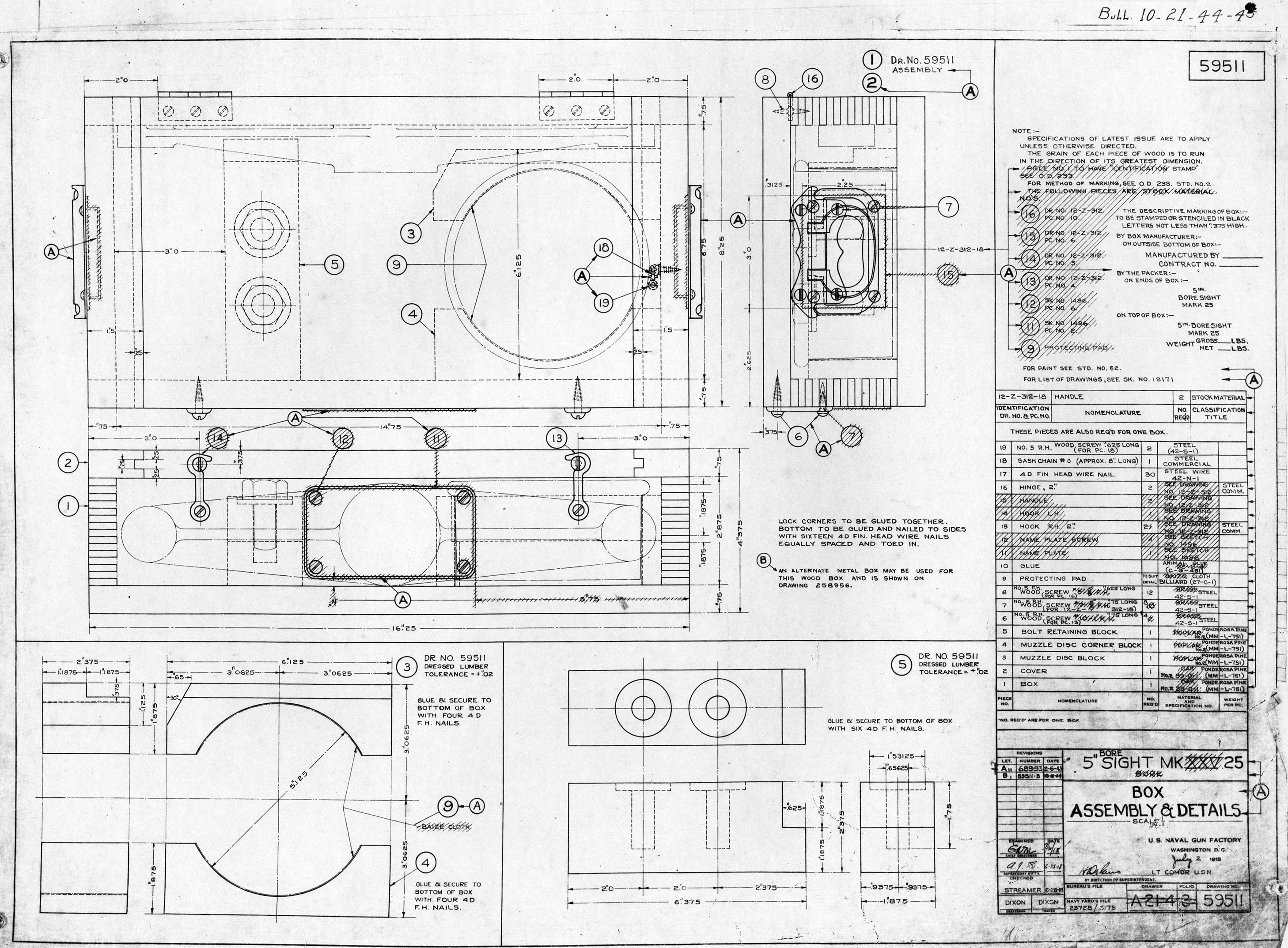
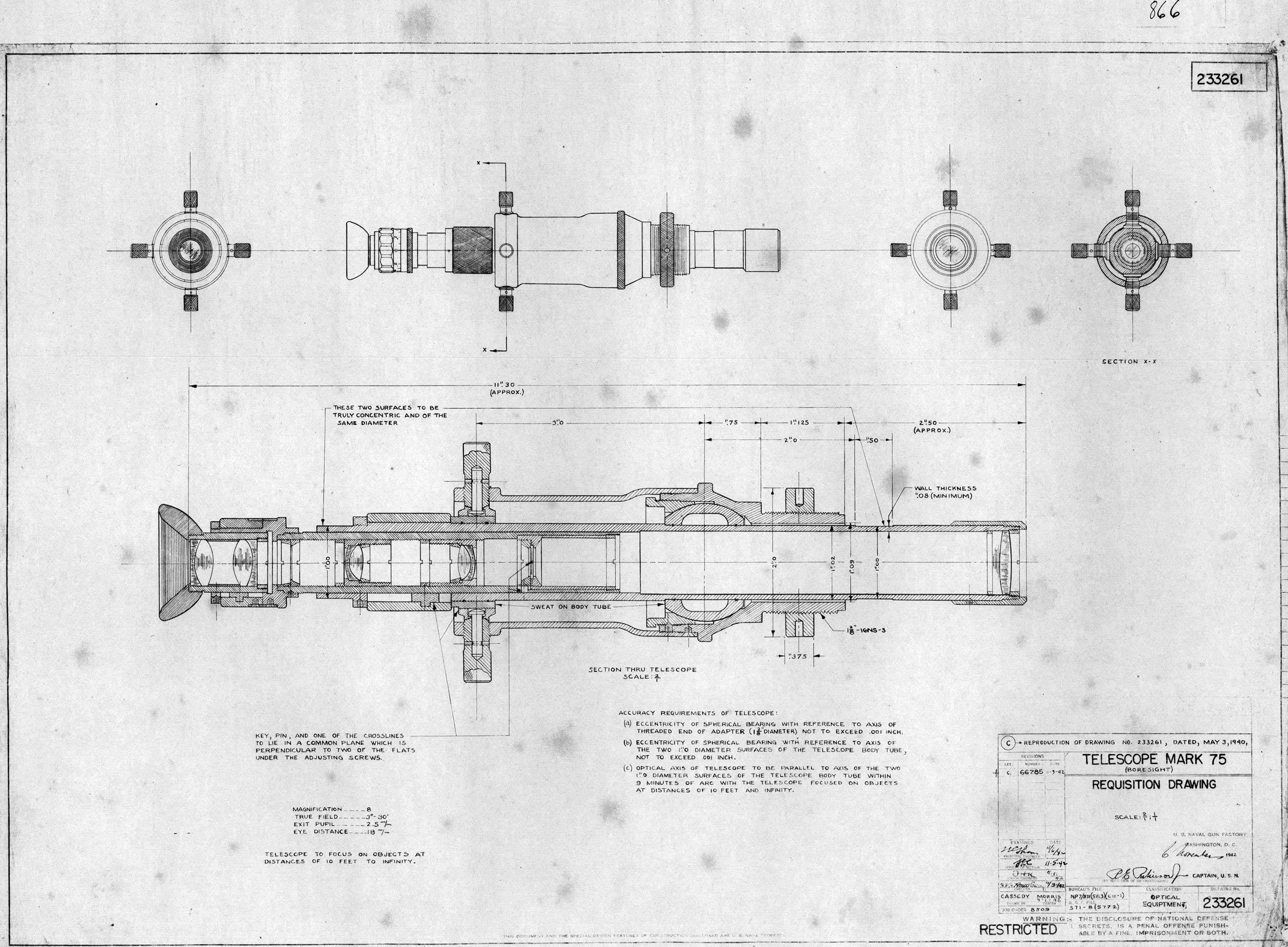
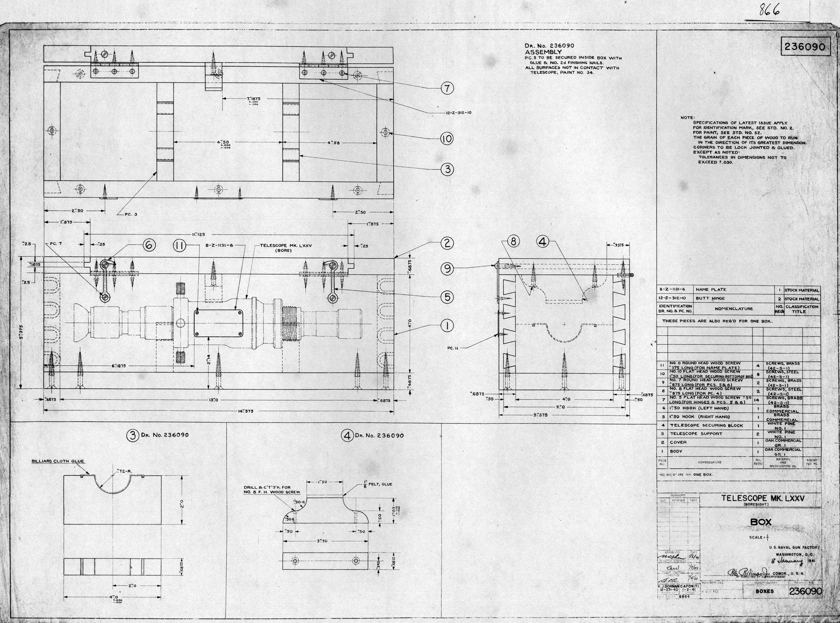