NOTE: These are actual working notes as well as project documentation. There are errors below. We will correct them as we find them. There is no shame in skipping to the acknowledgments and photos.
BACKGROUND:
USS Pampanito is a WW II submarine museum and memorial on Fisherman's Wharf in San Francisco. The boat is owned and operated by a non-profit and receives no government operating funds. Our goal is to make the submarine as complete and accurate to our summer 1945 restoration date as possible. This note is a description of the project to document and restore her long wire antennas, as well as a heartfelt thank you note to the individuals and corporations that helped make it possible.
During the summer of 1945 USS Pampanito had a major refit in preparation for the invasion of Imperial Japan. As part of this, her 4" 50 cal gun forward was replaced with a 5" 25 cal wet mount gun mounted aft. In this final configuration she also had two Bofors 40mm, a twin 20mm Oerlikon, and other small arms. These changes required changing the long wire antennas that were previously lead aft to lead forward to minimize interference with the main deck gun aft.
The antennas can be seen rigged forward in photos from our July 1945 target date, the reserve period (1960-1970), and then again at the beginning of the museum era (early 1980s). Sometime in the mid to late 1980s when the museum mounted a deck gun forward, the antennas were raised higher and lead aft, the spreader/horns removed, and the mast forward on port was removed. We guess that they were trying to look more like the war patrol configuration with antennas leading aft, and this required raising the antennas to avoid visitor interaction above the brow during low tide. To achieve this they made and installed a taller than historic mast aft and raised the outriggers on the conning tower. The pipe style outrigger on port with its top strut could not be raised or was rusted so they created a plate style outrigger similar to the original on starboard, shorter than the original on port (but longer than starboard) to accomodate two antennas on port. The mast they put aft was taller than war time as well. They removed the single mast on port forward with its stay. The stay was removed from the center mast.
Note we are also missing a second short VHF antenna CAGQ-66134 on the periscope shears with pressure proof pipe leading to the hull, and shear valve entering the hull. This was identical to the one on starboard, either could be used for VHF radio or IFF. We have documentation that it was removed from the periscope shears in 1955 with the IFF gear in the boat and this will be a future restoration project.
Also not part of this project, but related are the missing safety lines that ran centerline down the main deck. The stanchions, cleats and staples, wire, turnbuckle and pelican hooks are all missing. This might include a staple on the anchor light/antenna mast centerline forward. The long kick pipe for the anchor light wire is also missing. The ladder on port forward from main deck to the cigarette deck on the conning tower was removed and bars welded in the opening in the hand rails. We are not sure why only this one of four similar ladders was removed, but it probably had something to do with visitors reaching up to the antennas and spreaders before they were moved higher up.
The photos of Pampanito are best evidence of the antenna configuration during our target restoration date of July 1945. The drawing for USS Drum 126624 from April 1945 is the second best. Photos from other boats from late 1945 can help. This is followed by the Pampanito 1944 drawings with the antennas leading aft that can fill in some assembly details. Finally there will be modifications for visitor safety and/or available parts.
During summer 1945 the antennas where close to the height of the cigarette deck hand rails. This minimized interference with the Bofors 40mm guns. Signs of the original weldment at this height are still visible on the conning tower.
The spreader/horns aft of the insulation bowls look like they were added in 1945 to make it easier for crew to climb from main deck to cigarette deck without catching on the antennas. The Drum 1945 drawing called for moving the bowls which would have eliminated this problem, but they were not moved on Pampanito. We have not see spreader/horns in any of the drawings, or on other boat photos. We do not have a lot of photos of other boats modified in June/July 1945 so we really do not know how common this was.
Some bits of the antenna hardware we have might have been left over from the WW II or the 1960s reserve period, but the most of it likely came from Susuin Bay Reserve Fleet. So the loose hardware will not provide much evidence.
Research questions and restoration choices:
- We normally do not have visitors on starboard, so maybe move the starboard antenna back to the correct (lower) height and farther outboard by restoring the original position and length of the starboard spreader. Also replace the missing spreader/horn on starboard. This would allow interpretation of the 40mm gun depression stop on the hand rail, but would leave the two antennas on port higher than the one on starboard which might seem odd. One can look at this as an opportunity to tell the story.
- Restoring the antennas to the original lower height on port would make them more attractive to visitors to try jumping up to grab the spreader, spreader/horn, or antenna wires. Of these, the spreader horn is the most likely to be a problem (lower than the spreader.) So consider some scenarios: spreader left high and wrong construction with no spreader/horn, spreader restored to original height and pipe weldment construction with no spreader/horn, replica spreader inverted to be higher but a pipe weldment no spreader/horn, or complete restoration of both. Lead ins can be left coiled out of the way and only attached when in use with any of the scenarios above.
- Type of insulator. All porcelain type are visible in the best photos of Pampanito. The bronze end type are specified in the 1944 and 1945 drawings, and are much more common in photos of other boats, but the Pampanito photo rules.
- How to turn back on wire at the insulator where the rat tail (down lead) heads to bowl. The Pampanito 1945 photos look like there are two cable clamps and wire over a thimble in a shackle also in the insulator. The USS Skate photos also shows two clamps over a thimble, then a shackle to insulator. The Springer photos and the 1944 drawings look like a seizing on thimble as does the 1945 drawing. Even if the wire is pre-tensioned it will stretch and so they might have used clamps to allow for adjustment. The problem with this is the sharp turn aft will be hard on the wire. A small loop and a third wire in the clamp would solve that problem, but it does not appear in any of the evidence. So we will use clamps.
- Definition of an "open splice" that is specified in the drawings. After some research (thank you Chris J. for finding it in American Merchant Seaman's Manual Sixth edition) we are pretty sure this is just a splice without a thimble. For example on the rigging type, Jonny Ball insulators. The term is not used consistently in the 1944 drawing callouts.
- Did they have safety links on antenna insulator supports? The 1945 drawing has wires in the illustration of the turnback insulator on the conning tower that look like a safety link (labeled see Detail I-2, Ref 4, RM66F704 which we do not have.) We see safety links on other boat's 1945 photos and they were standard on surface ships. The photos of Pampanito we have do not have safety links on the conning tower end. We do not have good photos at the forward, mast end of the pendants so it is possible they were between the turnbuckle and the pendants. Although usually placed on the high end, the need to stagger the port antennas might have been a good reason to mount these forward, or they might not have been on Pampanito.
- Turnbuckles on antennas are not on the conning tower end in our photos. We see these in photos of other other boats in 1945 and post war on the forward end with the pelican hook. We have a couple of post-war boat photos with them forward with the pelican hook. The 1945 drawing refers to the pelican hook assembly that probably includes the turnbuckles. They only provide 5"-6" of adjustment in a span greather than 100 foot, but will make it easier to close the pelican hook.
- Offset of pendants to separate the downleads near the bowls on port. The clear photo from 1945 shows a short pendant on the outboard antenna port at the spreader, but just a shackle on the inboard antenna at the spreader. The opposite on the spreader/horn where the inboard has a pendant and the outboard just a shackle. This makes sense to maximise separation of the down leads heading to the bowls.
- Turnbuckles on mast stays are not in 1945 drawing. But they are in the Pampanito photos.
- Illegible length of middle antenna in 1945 drawing, maybe it says 83 or 88? Overall we know that near 80 foot was a sweet spot for WW II transmitters, but the lengths were not critical so why does the 1945 drawing have three different probably functionally equivalent lengths? Maybe to insure that only two pendants were needed while remaining less than 8 foot in length. Our 1945 photos are not great, but they look like they have only one pendant on each of the antennas (no jonny ball insulator is visible,) so we may use a single longer than 8 foot pendent.
- Antenna connection for modern radio club modern tuner. This was unfortunately mounted with holes in the historic fabric of the bridge on the port side of the bridge during the late 1980s. The radio club offered to move the tuner into the radio room (sitting on top of TBL) and then use the antenna trunk connections in the radio room. At least one of the members thought it might actually work better. This will also allow use of the starboard antenna easing safety concerns, and will allow the repair of the non-historic holes in the conning tower.
- Bolt on terminations for the lead-in on the short (80 foot), and clevis terminated antenna wires we have vs finding lengths of 110 foot 1/4" bronze wire and properly splicing. The best price we found for 110 foot bronze wire is approximately $6.75 per foot in 2023. Really we would like to find the donation of three fresh wires so we could do the spreader/horn and clamped turn backs properly without any extensions.
- What is the right technique to connect with the all porcelain antenna insulators? The best photos we have show a shackle pin directly through the porcelain if there are no bronze ends. There are notes that attachments should be arranged so there is easy movement in all axis and no binding on the ends of porcelain insulators. If used, the Johnny Ball rigging insulators should have open splices through the holes without thimbles or shackles.
- We want to avoid dissimilar metals in adjacent hardware. So the bronze wire should have bronze or copper thimbles and if spliced copper service. The galvanized splices on the long pendants should galvanized steel thimbles and galvanized wire service. The insulators become the separation between galvanized support and bronze/copper antennas or pendants. We may need to compromise and use some 316 stainless steel in place of bronze fittings based on what is available. Also note all pendants in the 1944 drawings were phosphor bronze wire rope, but not in the 1945 drawing where the long ones are galvanized. We will likely decide based on material availability. None of the photos or drawings we have show service over the rope on the thimble (bare rope in thimble.)
- Once the equipment list is done we are going to need wire, thimbles, shackles, etc. in both bronze, and galvanized, u-shackle vs bow-shackle. We will need to look for more of the correct style (vs just what we have) for several of the components.
We are still looking for drawings:
- Radio Antenna System General Arrgt. SS-309-S6700-126153
- Antenna Details-Suspension Details M.I. RM 66F704
- Antenna Lead-In Details for Subs M.I. RM 66F878A
- Submarine Antennae - Typical Details SS S6700 124133
- Submarine Antennae - Typical Details SS S6700 124144
- Submarines Antenna System - RE66J396A, RE66J-396B
- Bridge Modification SS228-S2406-?
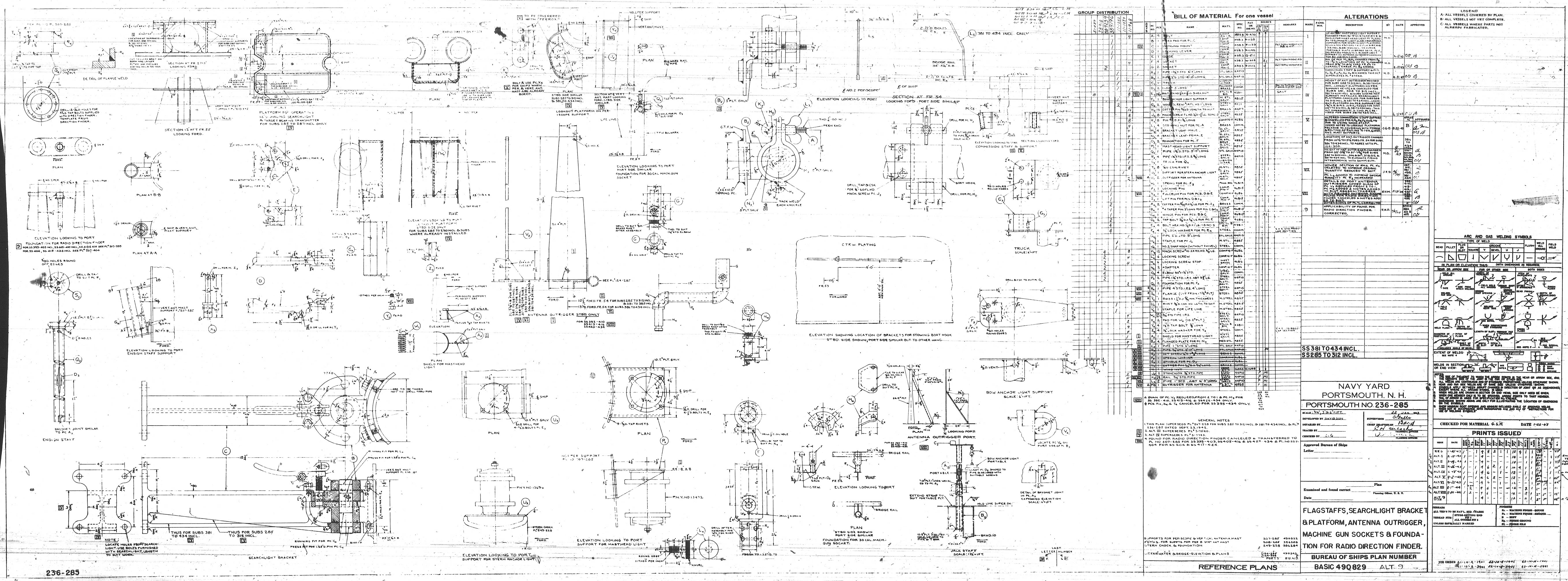
- Signal Bridge and Antenna Outriggers - 236-285, Basic 490829
- Pelican hook assembly RE 66F221
- Safety link assembly RE 10C2112
Manuals:
- Shipboard Antenna Details, Navships 900,121, 1946. Shows insulators and clamps.
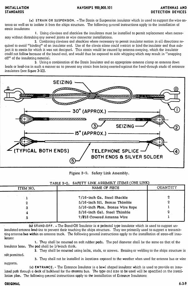
- Antennas and Detection Devices, Navships 900,000.101, 6-6-1. Has a post-war safety link design.
- Navships 900,109 section 3-61, insulators.
- Type CAGQ-66134 Antenna Assembly, 900,524-IB, 1944. Submarine VHF antenna configuration, we are missing one of these. sub-vhf-antenna-CAGQ-66134.pdf (4.5 MB).
References for rough calculation of lengths:
Frames 0-35 are on 24" centers. Frames 35-62 are on 30" centers.
Frame 12 to Frame 54 is 93-1/2 foot. Outboard port
Frame 10 to Frame 54 is 97-1/2 foot. Inboard port
Frame 10 to Frame 55 is 100 foot. Starboard
Conning tower fairwater at bridge deck should be 48-13/16" half width
Original port spreader was 24" + 37-5/8" = 61-5/8". The holes 1/2" and 24-1/2" from the outboard end. The replacement is only 48" long and plate construction. It is mounted at ~123" from main deck, higher than the original. It is about 128" forward of the pad for the missing spreader/horn.
Original stb. spreader was originally 37-5/8". The hole 1/2" from end. It is now 36" long with the hole at 34". It is now ~124" from main deck, higher than the original. It is forward of original position by approximately 30". The pad for the missing spreader/horn is about 114" aft of the spreader.
The center mast forward has the eyes for the antennas at about 80" off deck, and 30" apart. The pad eye for the stay to deck is about 78" from deck.
The missing port mast should be 40" from centerline and there is a welded reinforcing pad close to this location.
The spreaders on the conning tower where raised during the museum period, and the starboard one moved forward. If all of the measures matched the drawings (they don't), I think this would come out to roughly 94' port outboard, 98' middle port, 101' starboard span between mounting holes. With the roughly 80 foot antenna plus all the shackles, pendants, pelican hook, stays, and insulators these numbers make sense. If these are reasonably close (we need to take accurate measures after we decide about moving spreaders back or not) we will have one roughly 8 foot stay on the port wire, and two on the center and starboard wires. So we think the small variations in wire length may have been chosen to meet the 8 foot maximum stay length with a minumum number of stays. Note our insulators are shorter than the ones in the drawings. We still need to estimate the lead-in length which will be longer with the extra spreader/horns not shown in the drawing.
Some general notes:
- WW II transmitters could tune to a wide range of antenna lengths, but there was a sweet spot near 80 foot long for High Frequency (HF). A longer antenna would have been better for Medium Frequencies, but the TBL can tune onto almost anything.
- The TBL transmitter used separate antennas from the RAK/RAL/RBO/RBH-2 receivers. The transmitter would normally have been on the starboard antenna, but the crew could choose in the radio room.
- The center porcelain of an insulator is never painted, but the ends sometimes were painted blue for receive, red for transmit. The 1945 drawing says not to paint insulators.
- Receive antennas sometimes used shorter insulators on surface ships, but there is no indication this was done on submarines. The drawings and photos we have all use the longer insulators.
SAFETY:
- Antennas are tensioned to approximately 1% catenary (very tight) during installation and sudden release could cause components to become projectiles.
- Radio club will be energizing an antenna. It should be clear of visitor access or insulated anywhere it might cause a shock.
- We need to be more careful with everything on port where the visitors might jump to grab antennas, spreaders, etc.
PARTS:
Quantities in the list of below will change based on details we choose:
- Outrigger starboard. We think this is original, but it has been moved higher and forward during the museum period. This is couple inches short after cutting and re-welding in the new position. If we move it to the correct historic position it should be restored to the original length 37-5/8". It is made of 20.4# plate, 1/2".
- Outrigger port. The original pipe weldment was removed during the 1980s and the plate weldment style of construction was copied from starboard but made longer than port to accomodate two antennas, (but shorter than the original pipe construction,) and mounted higher up. It needs two 1/2" holes on forward edge if we leave it. If replaced, it should be with a 2" pipe construction, M4 pad eyes, and original length (51-5/8") even if mounted at the higher position with strut down instead of up.
- Single wire spreader/horn for starboard, probably 2" galvanized pipe, no drawing, but we have photos. For the pad eye see M4 on rails&stanchions, 17.5# steel plate is 7/16" thick.
- Double wire spreader/horn 24" between wires, 2" galvanized pipe for port. Pad eye for antenna M4. We will probably not replicate this because of visitor safety.
- Stanchion (mast) port. We think the original port mast was extended and moved aft in the 1980s. We have removed it from the deck aft, and removed the non-historic extension. The bottom is now short and uneven after having been cut free from deck twice. The top is missing a cap and the antenna pad eye is missing. A reasonable guess is that the antenna pad eye center the same height as the mast stay, and the mast stay on the center mast, roughly 78-1/2" from deck. We plan on restoring the bottom gussets to 15" width (to fit on 16" deck pad) while preserving the 60 degree angle. So the gussets will be 9-7/8" tall, 5-3/4" wide. The bottom pipe is 3-1/2" OD (3" nominal pipe). The forward pad eye for the stay is missing. We will model it based on X5 on rails&stanchions drawing. 20.4# plate is 1/2". That drawing also shows 1/2" overlap for different size pipe segments if we replace the lower segment.
- x2 Pad eye for mast stays on deck. One for missing port mast, one needed for center mast. See V4 on rails&stanchions. 20.4# steel plate is 1/2" thick. We need to look for weldment on deck, but if pad eye is roughly 78-1/2" off deck, stay is 60 deg., then about 45" forward of the center of the mast. We might also add a 1/4" pad to re-enforce the deck.
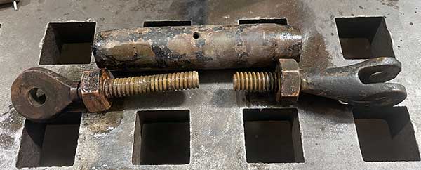
- x2 Mast stays forward. 5/8" (thread size) closed turnbuckle with 1/2" clevis each end. 7/16" bronze wire 1/2" clevis terminals on both ends, approx. 90" (check this.)
We have one assembly from aft that might be shortened. The terminals are the poured zinc type. The threaded rod on one end is half the length of the other.
We also have a bronze 3/4" turnbuckle with 7/16" terminal. To use this we will need a 7/16" open rope socket and 14 foot of 7/16" bronze wire rope.
We also have two 3/4" closed turnbuckles in stainless steel with 7/16" wire rope and terminals that have 5/8" pins and 1/2" clearance that can be shortened and used. They came out of Mare Island. These will need modifying the pad eyes to fit the 5/8" pins.
- x330 foot - 1/4" D (or 5/16"), 6x19 (or 7x19) bronze wire rope for three antennas. We have three pieces, but of two diameters, and one that is short. One of them is full of fish hooks (broken strands). We also have some shorter pieces that will be useful for the lead-ins to the bowls.
- x3 insulator suspension assembly on spreader/horn. Each has shackle with pin in spreader/horn, second shackle with pin in insulator, third shackle with pin in insulator. x2 wire clamps and thimble for turnback.
- x3 insulator suspension assembly on outriggers. Shackle with pin in spreader, 12" stay with splices over thimbles on both ends, shackle that fits in insulator, all porcelain insulator (ours type 61013, 10"), shackle that fits in insulator. Note on port inboard the short stay goes on the spreader/horn and the extra shackle on the spreader.
- x3 Pelican hook/turnbuckle assembly. Long shackle with pin in mast pad eye shackle in pelican hook bail, pelican hook, turnbuckle, shackle to stay. We have a drawing for the handrails showing a 3/8" two link style hook that might have been used. We had four 1/2" pelican hooks donated. x3 for the antennas and we will need more of these for the center safety lines some day. There are custom turnbuckles in the drawings for the antennas (1/2" threaded rod, 3/8" pin, two clevis, approximately 6" of adjustability.) We have x3 donated bronze turnbuckles with a clevis on one end and wire terminals on the other end. They have about 4-1/2" adjustability. We will need to replace the wire terminal end with a clevis.
- x3 pendant assemblies on the antennas. Thimble with two clamps forward to make these adjustable length (these were probably spliced) and spliced over thimble on insulator end. Extends the approximately 80 foot antennas as needed. Drawings show no pendant should be greater than 8 foot long and a rigging insulator and extra pendent added if more than 8 foot needed. Our photos are not clear but look like single pendants on all three wires. Bronze 1/4" wire rope in 1944 drawings, galvanized steel in 1945 drawings. We bought 1/4" brown porcelain rigging insulators (Jonny ball) in case we need two pendants on any of the wires.
Small fittings from above. Thimbles, shackles, cable clamps:
- x9 Thimbles for 1/4" or 5/16" bronze wire. Copper or bronze preferred, if not stainless steel.
- x18 D-shackle with pin, 5/16" or 3/8" pin, 1-1/4" throat, 2" depth, bronze or stainless, antenna thimble to porcelain insulator
- x3 D-shackles with pin, 5/16" or 3/8" pin, 5/8" or greater throat, 2-1/2" depth, galvanized or stainless for mast pad eyes to the pelican hooks.
- x9 Bow or D-shackles with pins, 5/16" or 3/8" pin, 5/8" throat, galvanized or stainless, standard depth for shackle to thimble connections.
- x18 Bronze cable clamps for antenna and spreader/horn bronze wire at insulators. To handle 1/4" or 5/16" wire. We would like to have real clamps designed for loading instead of using split bolts.
- x24 Galvanized or stainless cable clamps, 1/4" for short stays.
- x12 Galvanized or stainless thimbles, 1/4" for short stays.
- 1/4" galvanized wire rope 75 foot
- x? foot Rubber hose 7/16" ID as needed to protect crew near bowls. Standard oxygen (green) welding gas hose. We have this stock.
- x? Copper wire #16 B&S gauge, soft copper, for service on bronze splices as required. We have this stock.
- x1 Cable grip that will not destroy the 1/4" or 5/16" bronze wire rope for use during tensioning.
ACKNOWLEDGMENTS - THANK YOU!
We appreciate the advice, help, donations and discounted products and services from individuals and companies along the way. We had the help of an very talented team. We could not have succeeded without the incredible generosity of these people and companies:
Rich Pekelney, Pampanito Volunteer was the project manager.
DONORS:
Hydrasearch Company LLC, pelican hooks, https://www.hydrasearch.com
Jake Roulstone, turnbuckles
ppelectronics on Ebay, discount on insulators
Richard Pekelney
PHOTOS:
Yes we know these photos are pretty hard to see detail.
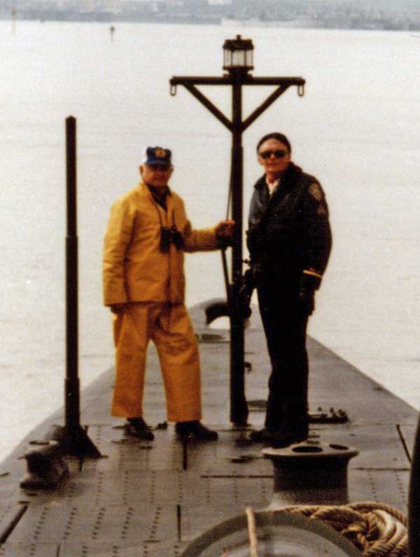
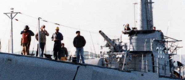
1945. Pampanito starboard side best photo.
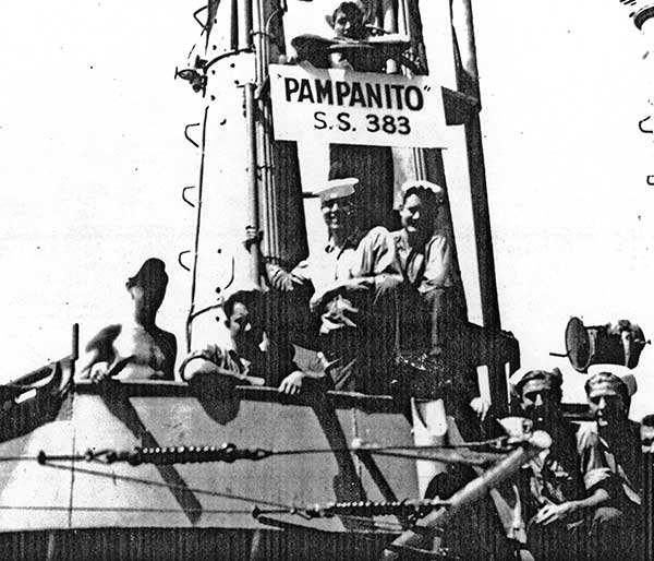
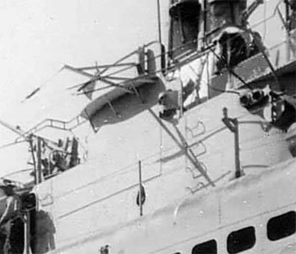
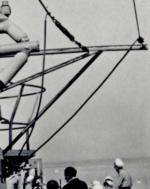
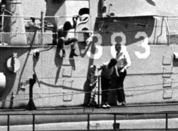
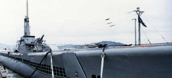
1945. Pampanito port side. This is the best photo we have of any part of the antennas on Pampanito. It looks like they used cable clamps instead of seizings on the turn back, shackles on the porcelain only insulators.
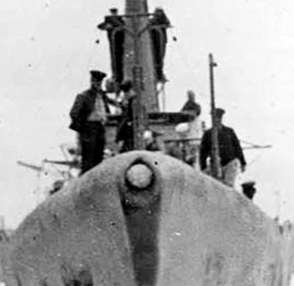
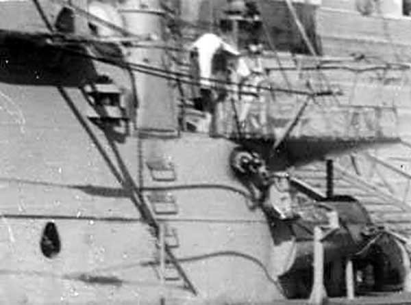
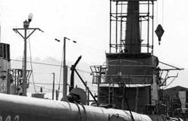
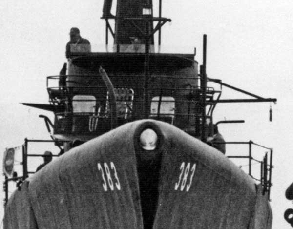
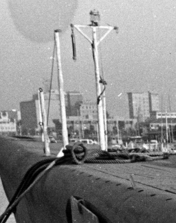
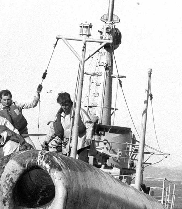
1945. Pampanito bow. Turnbuckles on mast stays. What might be pelican hook and turnbuckle near mast. The rest of the photo makes it look like just one stay before insulator, but a small rigging insulator could easily be missed in the photo.
1945. Pampanito
1945. Pampanito
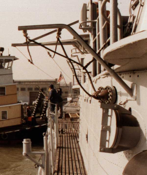
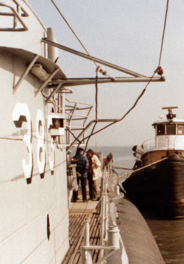
1945. Pampanito port side.
1946. Pampanito port side.
1946. Pampanito port side. Outboard antenna has short pendant on spreader, but not on spread/horn aft of bowls. Inboard antenna is the opposite, no pendant on spreader forward, but one aft on spreader/horn. Inboard antenna lead in on the forward bowl, outboard lead in on aft bowl.
1945. USS Skate showing use of cable clamps on the antenna turn back to lead in. Also a short, clamped pendant on the inboard antenna that heads up. Spreader is aft of bowls with two supports heading down.
1945. USS Skate showing shackle pin directly in the all porcelan insulator.
May 1945 USS Lionfish. The photo has details with the antennas leading forward from May 1945.
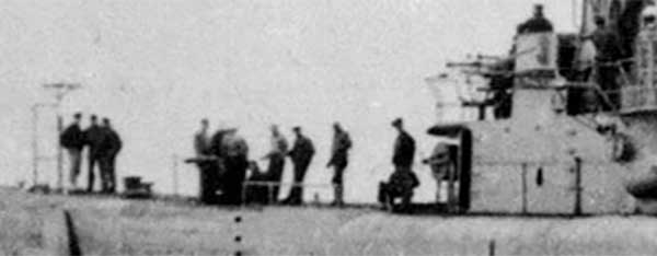
1960s. Pampanito bow while reserve training boat. Note the spreader/horn height looks about halfway between the rails.
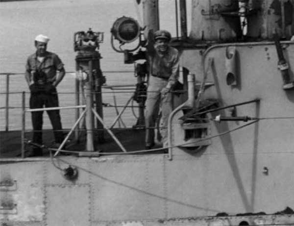
1960s. Pampanito starboard while reserve training boat.
1981?
1981?
1981. Starboard.
1981
1981
Museum era return from drydock. The spreaders are original, hanging wire and insulators are museum era.
Museum era return from drydock.
Late 1980s at the museum.
Late 1980s at the museum.
Late 1980s at the museum
1986? Note the kick pipe was still on the center stanchion. Port mast was in place. Port outrigger was in place.
2022. Kick pipe for wire, and mast stay are missing. Maybe a ring forward for a lifeline forward.
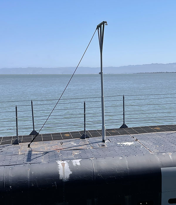
2022. Museum era, too tall mast aft before removal. Maybe constructed by extending the short mast that was forward port.
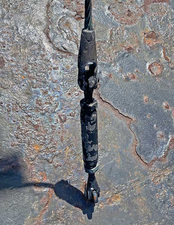
Jul 2023. This is the turnbuckle found on the mast stay aft. It must have a story, there are different length and diameter screws. The clevis is racked (bent to one side.) 94175
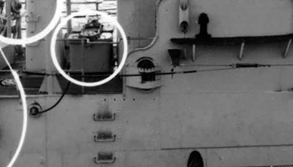
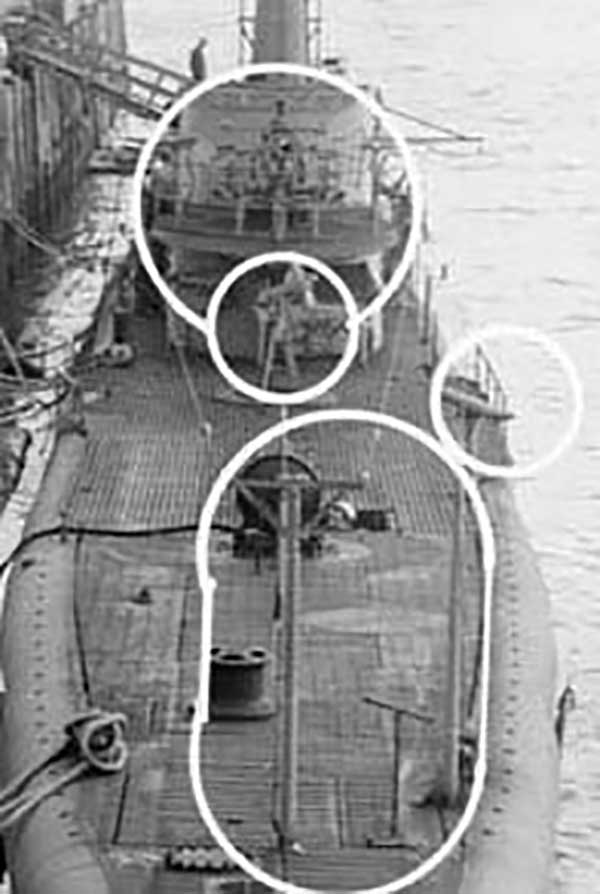
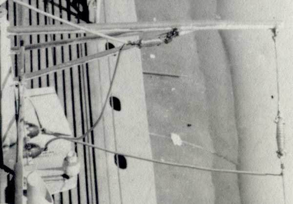
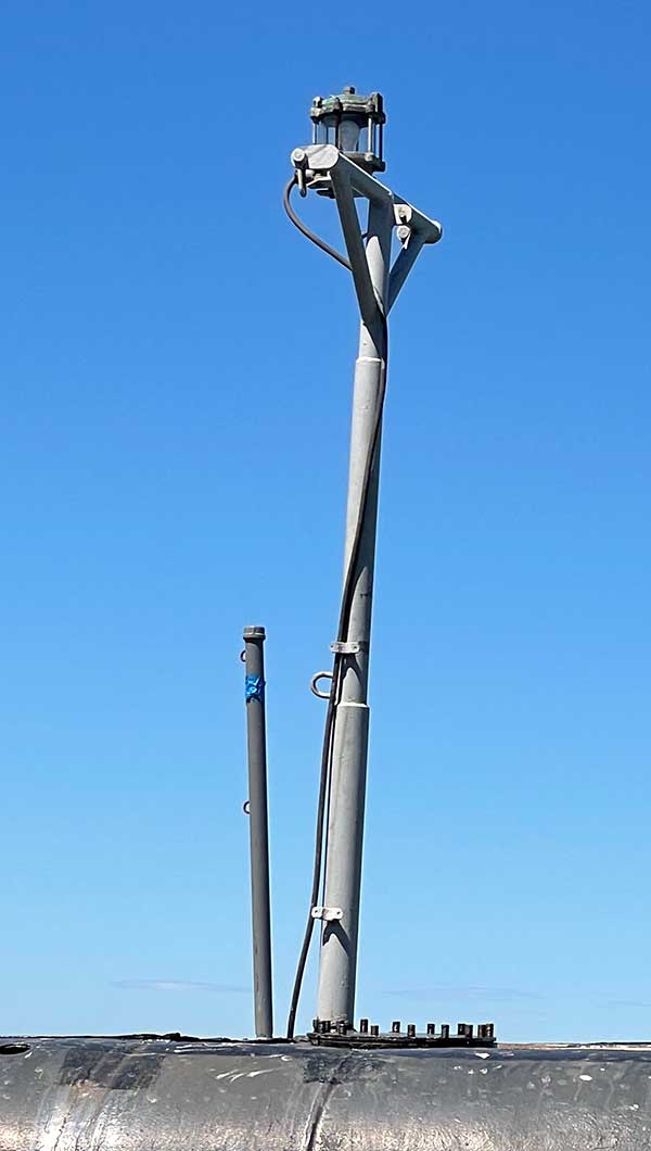
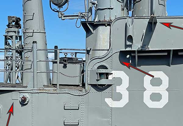
2023. On port side. The arrow on the lower left shows the pad where the spreader/horn was based, just aft of the insulator bowl. The middle arrow shows weldment where the outrigger was, close to the height of the hand rails. The arrow on the right shows where the outrigger was moved during the museum period to be as high as they could put it.
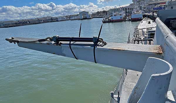
2023. Non-historic port outrigger. This is too short, wrong type construction (plate vs pipe), shackle holes are aft, and mounted higher than original.
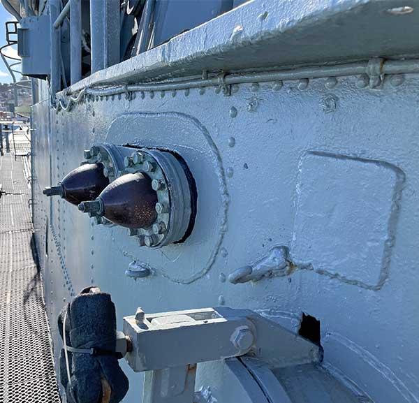
2023. Twin insulator bowls on port. The square pad is where the spreader/horn was installed. The hooks look a lot like the ones used with a removable center antenna, maybe we had this before the SV radar installation.
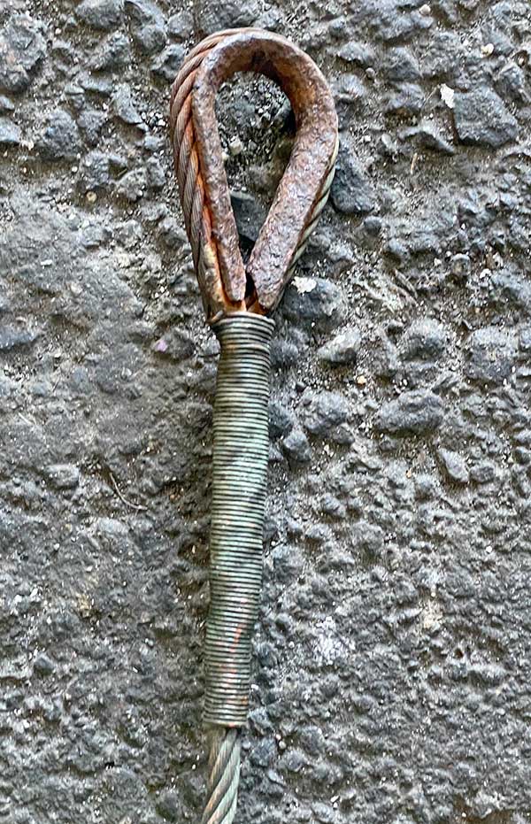
2023. This is the only example of splice served with copper wire that we have. Unfortunately made on a steel instead of bronze or copper thimble.
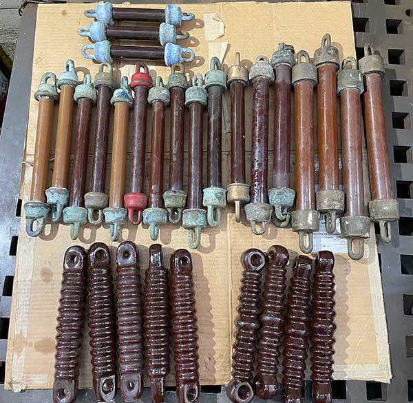
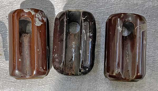
2023. We have several lengths and diameters of suspension insulators:
With bronze ends: x3 10", x9 14.5", x3 15.5", x2 16.5", x4 18.5".
All porcelain x5, 10" centers, 12-1/4" overall, 1.1" wide on end, .46" hole, CBO 61013 LAPP. RE61AA 196
All porcelain x4, 10" centers, 12-1/4" overall, 1.3" wide on end, .5" hole, CPP 61013A. RE61AA 196
2023. We will need a lot more bronze and galvanized shackles, thimbles and all the clamps.
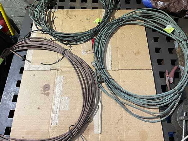
2023. Bronze 6x19 long wires we have:
* 80' 9" long 5/16" diameter center pin to center pin with clevis on both ends. This will need a extra wire lead in from the bowl and clamps on the antenna.
* 99' 6" long 1/4" diameter with splice over rusty thimble with copper wire service on end, open other end
* 114' long 1/4" diameter with bad ring terminal on one end. This has brokens strands sticking out.
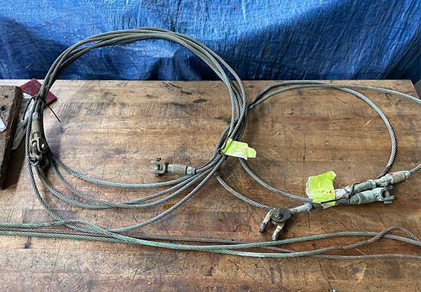
2023. Bronze 6x19 short wires we have that can be used for lead in or stays:
* x1 4-1/2 foot 5/16", x1 6 foot 5/16", x1 6 foot 1/4" with ring terminal.
* x1 24' 7" long 5/16" diameter center pin to center pin with clevis fittings on both ends
* x1 9' 8" long center pin to center pin with clevis on one end, turnbukle on other end
* Not shown, a 57' long, 1/4" diameter, 7x19 bronze wire.
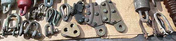
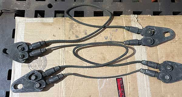
2023. Safety links. We have two of this 5/16" design that is not shown in our drawings. The concept is that the thinner shorter wire breaks first under shock load and the heavier wire catches the load instead of having the whole antenna fall to deck. I.e. a purpose built weak link. The WW II drawings we have are setup for 1/4" wire, post war surface ship documents show 5/16" wire with this type hardware.
This shows another method of construction of a safety link with splices. This came out of a post-war document. It notes that the link is usually designed so it has a breaking strength of 1/4 of the strength of the wire rope in the antenna.
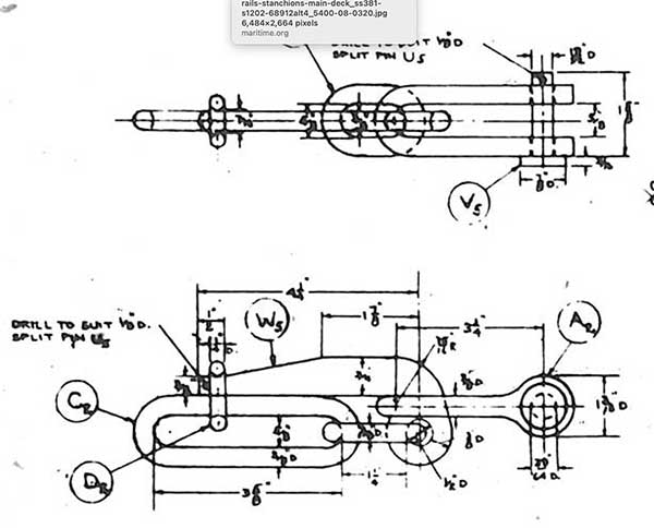
Typical double link body type pelican hook for a safety line from WW II drawing that fits 3/8" shackle.
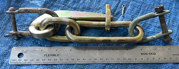
2023. This is one of the modern (NSN 4030-00-266-7408) 1/2" pelican hooks that was donated. We are not sure what size was used on the antenna in 1945, but it is the smallest double link body type we could find and is designed for 5/16" shackle. Overall length 7.875", main link stock dia. .5", main link inside length 4.5", hinge link inside length 1.75", accommodated material dia. 3.12"
2023. 3/8" hole rigging insulators (Jonny Ball). Purchased from Fair Radio Sales. We thought we would need two of these based on the drawings, but may not need them based on one of the photos.
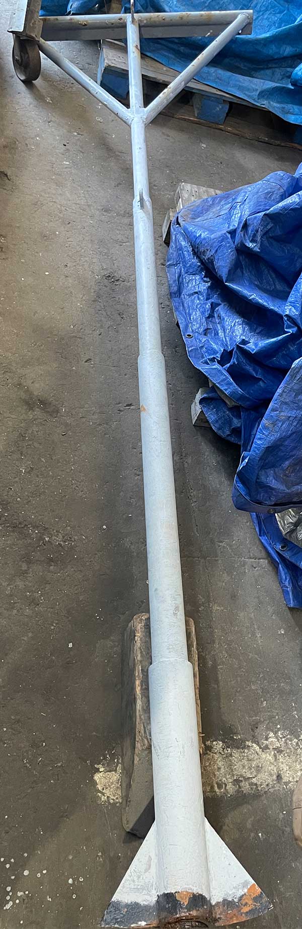
Apr 2023. The aft mast after removal. We think this was the mast on port forward, extended to make taller and with the added crossbar. Approx. 5" of the bottom has been lost while being cut off the boat twice.
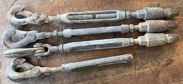
Jul 2023. Bronze turnbuckles donated. We will remove the scissor hooks, and need to find or make a bronze clevis to replace the 7/16" wire rope terminals on the right hand end (right hand thread, 1/2"-20). Or replace them with new 1/2" turnbuckles. These will work between the pelican hook and stay.
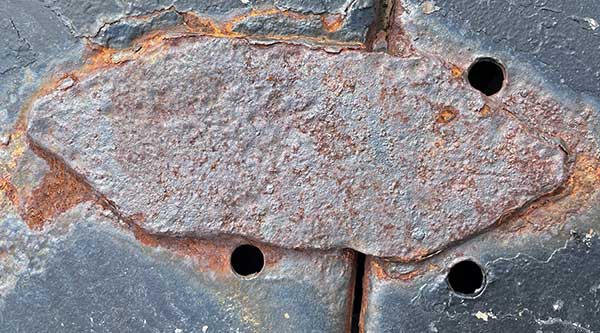
May 2023. Welding pad for antenna mast forward on port. Approximately 6" x 16". There is some weldment, but no pad for the mast stay eye about 45" forward of the pad. This is consistent with a roughly 60 degree stay attached roughly 78" off of deck with roughly 90" long stay.
Jul 2023. We started making the pad eyes needed for the mast stays. After this photo we expanded the holes to accomodate larger diameter clevis pins.
