NOTE: These are actual working notes as well as project documentation so there will be changes. There is no shame in skipping to the acknowledgments and photos near the end. There are probably omissions & errors to fix in this note, please let us know about any problems you find.
BACKGROUND:
USS Pampanito is a WW II submarine museum and memorial on Fisherman's Wharf in San Francisco. The boat is owned and operated by a non-profit and receives no government operating funds. Our preservation goal is to make the submarine as complete and accurate to our summer 1945 restoration date as possible. This note is a description of the project to restore our 20mm Oerlikon gun mounts and a heartfelt thank you note to the individuals and businesses that make it possible.
On 2 Aug 1945 Pampanito had a twin 20mm Oerlikon gun forward on the foundation that previously held a 4"-50 cal gun (and elsewhere a 5" 25 caliber wet mount gun, two Bofors 40-mm, x4 .50 cal. machine guns with x3 of them stowed in lockers on deck, and small arms stowed inside the boat.) Pampanito was donated to our non-profit by the Navy in 1978 with no guns. Over the years the museum has acquired replacements for all the other missing large caliber weapons and their foundations.
The goal of this project is to restore a Mk 24 twin 20mm gun mount to be as complete and accurate to the summer 1945 submarine configuration as we can while preserving as much of the historic fabric as possible. This mount will be on the forward main deck gun foundation.
Pampanito carried single 20mm Oerlikon mounts on her six war patrols before being upgraded in summer 1945. So on a lower priority basis we restored a Mk 10 single 20mm gun mount to 1945 submarine configuration for shoreside display.
All the gun mechanisms are demilitarized (unable to load a cartridge in chamber, fire, or pass a projectile through the barrel). We we are not simulating firing.
Gun Mount Mk 24 Mod 2 is a Mount Mk 10 single mount design modified to have two Mk 4 Mod 1 guns, simple site Mk 4, trigger on handle bar, and an improved (quite different) cam depression stop mechanism. Mk 24 Mod 5 has other small improvements in the cradle, carriage and stand. This includes omission of the sheave for cocking tackle and a ball bearing in stand pivot.
Twin 20mm Gun Mount Mark 24 Mod 5 consists of:
Machine gun mechanism Mark 4 Mod 1 (x2)
Gun Barrel - Mark 4 or Mark 4 Mod 1 (x2)
Sight Mk 4 Mod 1
Magazine Mark 4 Right hand (same as single)
Magazine Mark 5 Mod 0 Left hand (grey zig-zag stripe)
Shoulder rests and handle bars Mark 8 Mod 0
Stand Mk 7 Mod 23
Carriage Mk 18 Mod 0
Cradle Mk 14 Mod 0
Single 20mm Gun Mount Mk 10 Mod 1 consist of:
Machine gun mechanism Mark 4 Mod 0
Gun Barrel - Mark 4 or Mark 4 Mod 1
Sight Mk 4 Mod 1 or Mk 5
Magazine Mark 4 Right hand
Shoulder Rest and Hand Grips Mk 5
Stand Mk 7 Mod 1
Carriage Mk 7
Cradle Mk 5
Submarine mounts do not have shields, or Mk 14 sight or sight adapter equipment Mk 2. We do not know if sight Mk 4 Mod 1 and/or spent cartridge bag were used on submarines. They are not installed in any of the combat photos or videos we have.
Twin mount assembled weight without guns or shields ~1,000 lbs
Single mount assembled weight without guns or shields ~700 lbs
Gun with barrel and mechanism (without magazine) 150 lbs
Barrel alone 46 lbs
Sight Mark 4 is 13 lbs
Loaded with 60 rounds a magazine is 63 lbs, empty 31 lbs.
References to NOP are the Naval Ordnance Plant. The NOP in Center Line, Mich. operated by Westinghouse during the war made many of the 20mm guns. The Pontiac Motors division of General Motors also produced many guns. MOM is stamped on 3 of our magazines, this might be Modern Welding Company that produced mounts.
MANUALS AND REFERENCES:
Ordnance Pamphlet No 1439 Twin mount Ordnance Pamphlet No 911 Gun Mechanism, and very important changes and circular notices op-911-changes.pdf (2.1 MB) Ordnance Pamphlet No 909 Single Mount
Ordnance Pamphlet No. 3476, 20 MM A.A. Single and Twin Mounts, All Marks and Mods, Illustrated Parts Breakdown, 1967. 20mm-navord-op-3476-ipb.pdf (11.2 MB)
Ordnance Pamphlet No. 826, 20MM Antiaircraft Gun-Mark 4 and Mark 2, Extracts from OP 813, 1942. (not online)
BR 274, Handbook and Drill for 20mm Oerlikon Machine Gun Marks II, II USN and IV USN on Marks I, IIA, IV US, V US VIIA and VIIIA Mountings. 1943 (not online, Crown Copyright, available by request directly from the Royal Armouries)
Range Table for 20-MM A.A. Gun 2,725 F.S. Initial Velocity, OP 945 (not online)
Machine Gun Bulletin No 2 - 20mm Machine Gun, 1942. These are operating instructions for surface ships, with a good list of failures at the end. 20mm-mg-bulletin-no2.pdf (6.1 MB)
We have most of the detailed drawings for the single and twin mounts. The single drawings are from a folio book in the collection of USS Cod that we borrowed and scanned in 2010. Twin mount drawings were scanned by the USS North Carolina in 2022, and USS Slater in 2023. We have drawings for the gun mechanism, but not online.
OD 2929 at the beginning of the drawings page is an OE number to/from navy part number cross reference. Also see the back of the manuals for more cross references and parts illustrations.
Favorite twin mount Mk 24 cutaway and assembly drawings:
Color mount general arrangement OP 1439 Plate 2
Mount General Arrangement 492472 and 492473
Cradle General Arrangement 487474
Carriage General Arrangement 492476
Stand General Arrangement 487479
Working Circle 492496
Color Gun Mechanism General Arrangement OP 911 Plate 1
Gun Mechanism General Arrangement 299825 and 299826
Magazine Mk 4 RH 299706
Magazine Mk 5 LH 367739 and 367740
Sight Mk 4 Mod 1 299821
Single Mk 10 Mod 1 drawings (we are missing depression stop, and the type of handle bars in our photo):
Sketch 103308, Assembly 86 103308-4
Mount General Arrangement 367551 and 367552.
Carriage Mk 7 365908
Cradle Mk 5 367731
Stand Mk 7 Mod 1 367528
Sight Mk 5 300017
Shoulder Rest and Hand Grips Mk 5 367644, 367645
Videos:
- Youtube CAD generated animation of operation, by Vbbsmyt
- Submarine firing at a mine, 1945. Inside a pressure proof locker holding Bofors 40mm magazines at 0:21. Twin 20mm Oerlikon firing at 1:01. No sight, no cartridge bag.
- Submarine 1945. Shows holding a magazine in the space between deck battons (instead of a loading frame) and tensioning at 1:27. Cocking both guns at the same time 1:40. No sight, no cartridge bag.
- USS Barb, 1945 Single mount with wide handle bars, pipe rail depression stop, no cartridge bag, no sight, magazine locker in deck. 0:43. Trigger on left handle bar 1:28.
- Live Firing at Stone Mountain 2017, by Novectaner (not our gun)
MK 7 projectile for Oerlikon is 20mm x 110mm RB (RB is rebated base, a rim that is significantly smaller in diameter than the base of the case) Ordnance catalog pages for 20mm projectiles Ammunition description in OP 911 manual
British handbook for 20mm Small Arms Ammunition, 1943. gun20mm-26-pubs-5566-ammo.pdf (3.1 MB)
B.R. 932, Handbook on Ammunition, 1945. British Navy ammunition from WW II br932.pdf (21 MB PDF)
We have collected BUORD stock hardware and tool drawings (8-Z-x-x and 12-Z-x-x) BUORD part numbers that are useful when working with the drawings.
During the early 1980s, the museum cobbled together a single 20mm mount from USS Silversides (it had a tripod stand with horizontal depression cam like a twin, plunger type cradle lock in the carriage typical of pre-tripod mounts, and a spring operated external carriage lock above the depression cam), an incomplete Mk 4 mod 0 gun from a federal agency, shoulder rests and a magazine from Jeremiah O'Brien, and a sight from a private collector. Together they were assembled into a single 20mm that was displayed for several years. A 20mm Mk 10 single mount with matching serial numbers without a gun was acquired during the mid-1980s. A second Mk 4 gun was acquired sometime in the early 1990s. Finally a third Mk 4 mod 1 gun without a barrel was acquired in the 2000s. The single mount was displayed forward on the conning tower with occasional removal of the gun for paint. At some point the two single mounts were swapped (the numbers matching Mk 10 mount was put on the boat, the first mount in storage.) Later still the museum traded with PT Boats Inc. the first single mount then in storage without a gun for a twin 20mm mount without guns. Neither traded mount had the carriage or cradle locking, depression stop, sights, shoulder rest, trigger, cartridge bag, belt, or cocking bar parts. Sometime after the twin mount arrived, the twin carriage and cradle was swapped with the single carriage and cradle on the boat.
When leaving for Pampanito's 2021 drydocking mount then on the boat was removed for restoration and eventual return to the correct 1 Aug 1945 location on main deck forward. As found in 2021 both guns on the twin mount were missing parts, both magazines were badly rusted, one gun was set up as a single (Mod 0), the other has Mod 0 markings but with a Mod 1 (twin type) breech casing cap. The mount was missing many parts and all the parts were frozen in place. The twin carriage and cradle were installed on a single stand. The single mount was striped bare, the gun mechanism for it was in better condition the twin gun mechanisms but missing significant parts. Neither the mount or the gun mechanisms had ever been properly restored.
The data plates are missing from our Mk 24 mount. The carriage casting is 492480-1, hand stamped 2225, and does not have a cocking sheave. The trunnion height is approximately 47" and stand lower bearing is ball type, so we think this a Mk 24 Mod 5.
The guns and magazines on the twin mount:
20mm M.G. Mech. Mk. 4, Ser. No. 109987 N.O.P. Center Line, has C2453 stamped on the bottom of the breech casing.
20mm M.G. Mech. Mk. 4, Ser. No. 219775, G.M. Corp., has 50595 stamped on bottom of the breech casing.
20mm Barrel Mk 4 Mod 1, 141132, B17864, OE-1013-C
20mm Barrel Mk 4 Mod 1, 348030, OE-1013-K
20mm Magazine Mk 4, right hand, stamped NC
20mm Magazine Mk 5, left hand, stamped MOM
Interpretation 20mm magazine Mk 4, right hand, marked MOM, loaded with 60 donated dummy cartridges. (Cont)
About half way through our restoration USCG-11 generously donated the remains of a Mk 24 twin 20mm mount after they removed parts for their single mount restorations. The mount had been unused and stored outdoors at USS North Carolina since the 1970s before being donated to USCG-11. It was in rough shape, flakey paint, rust, pitting, missing handle bars and base of stand, front of the cradle cut off, broken carriage lock plunger, broken pivot retainer pin, many other missing parts. However it had most of the depression stop, and many of the external trigger linkage parts we needed. It facilitated a huge leap in our restoration. USCG-11 also donated some of the depression stop parts from a Mk 10 single 20mm mount, and a very rough left 20mm magazine that will be partially restored then donated to Columbia River Maritime Museum. The twin mount and single parts arrived 25 July 2023. We needle scaled them to remove loose coatings after testing for lead paint. The parts we are planning to use have been removed. The remainders of the twin mount are being offered to other museums.
20mm Assembly Mk 24 Mod 5, NSY. Stand Mk ? Mod 23, 524950 (mark is not legible, probably Mk 7 stand)
Single mount:
The information below is on the data plates from the single mount, these were painted over at some point, but we have photos. The serial number (175094) is the same on the single carriage Mk. 7 (78 lbs) and cradle Mk. 5 (95 lbs) found in the warehouse, and the stand found on the boat. The paint colors, stand height, etc. also all matched. This is how we verified that sometime after the twin mount Mk 24 arrived at Pampanito the carriage and cradles were swapped on the single and twin stands. The matching serial number parts were re-united during this restoration:
20mm Stand
MK ?? Mod 1 (mark is not legible, it should be Mk 7)
WT 325 Serial 175094
USN Ord Plant Center Line Mich.
Westinghouse Elect. & Mech. Co.
Assembly No. 86
20mm Mount
Mk 10 Mod 1
USN Ord. Plant Center Line Mich.
Westinghouse Elect. & Mech. Co.
No ORDALTS are stamped on the data plates, but this mount has an uncut depression cam installed and the mounting holes for the rest of the assembly, it also has the threaded hole and wear marks on the carriage for a cocking bar.
Gun FIC for the single mount restoration:
20mm M.G. Mech. Mk. 4 Mod-1, Ser. No. 130618, N.O.P. Center Line.
20mm sight Mk 5 is in the assembly list. We have a Mk 4 Mod 1 sight complete in box that we can use instead. But it is also likely no sight was installed during submarine operation based on war time photos. (FIC)
20mm right hand magazine, 299706 OE-1530. (FIC)
Other found in collection (FIC), donated, and replica parts:
x1 299666-2 OE-1308 securing bolt missing spring pins
x2 299666-4 damaged spring pins for OE-1308
x1 299676-1 OE-1058 barrel spring seating ring retaining catch
x1 299666-1 OE-1316, breech cotter
x1 299680 OE-1034 magazine interlock and ejector assy
x1 empty right hand magazine (ABC)
x1 empty left hand magazine with a section cut out (LS)
x1 empty left hand magazine in rough condition from USCG-11 for CRMM (LS)
x1 455386 left cocking bar replica
x1 455385 right cocking bar replica
x2 454138 cocking bar clip replicas
x1 single cam limit stop bracket with cam limit stop carrier assembly
x1 set of remains from USCG-11 twin mount described below.
RESTORATION PLAN:
The primary goal is a complete submarine configuration Mk 24 twin mount on Pampanito's forward gun foundation. The submarine configuration does not include shields or Mk 14 gunsight. A lower priority goal is to restore our single mount Mk 10 with gun. The single will be used for shore side interpretation and will be restored as close as we can to the last war patrol configuration as shown in the summer 1945 photo. This includes double loading stop, barrel spring center, handle bars with trigger instead of shoulder rests, cam depression stop, and cocking bar.
In general the work on the twin mount stand, carriage, cradle, and forward gun mount were the first priorities so the mount can be installed on deck of the boat and interpreted at the first crane availability for loading. Note the guns can be hand carried on and off the boat as needed.
Priorities (these may change:)
DONE- Collect together manuals, drawings, photos, stories. Put the most useful information online.
DONE- Disassembly, coatings removal, rust removal of the mount, gun mechanisms and magazines. Complete the list of what is missing or broken. Identify parts to be repaired, vs bought commercial vs made in our shop vs outside donated.
DONE- Repair the twin stand pivot. Return the twin and single carriage/cradles back to their original stands.
DONE- The cradle lock is needed to safely assemble and maintain the mount.
DONE- The carriage lock is needed to keep the gun from swinging with boat movement.
DONE- Shoulder rest support brackets.
DONE- Sight mounting hardware. We still need an eyecup for display.
DONE- Cocking bars and clips for the mount.
DONE- Repair for display the two magazines that were installed.
DONE- Complete two sets of barrel springs.
DONE- Replace missing barrel lock handle assemblies on both display guns.
DONE- Replace missing trigger parts on both display guns.
DONE- Test assemble/fit both display guns, and test fit mount with guns installed.
DONE- On the boat forward gun foundation steel coatings and replacement of wood bed.
DONE- Overhaul then load the extra right magazine with dummy (inert, drill) ammunition. Visitor proof for interpretation.
DONE- Repair torch cut mounting holes in stand. Drill mounting bolt holes in the twin stand to match non-standard forward gun foundation holes.
DONE- Depression cam stop assembly. Just need to profile the cams after installation.
DONE- External trigger handle, links, etc on carriage. Some rework is needed on a couple of the replica parts.
- Non-historic carriage lock to protect the carriage lock plunger and pivot retainer pin.
- Coatings and visitor proofing of mount and guns before installation on the boat.
- Cover for winter and rain
- Shoulder rest buckle and strap for interpretation.
- Cartridge bag. Low priority because we have no photos in war zone with these in use on submarines.
- Tools as needed for stripping, assembly, and interpretation.
- Other on the boat items. Missing pressure proof locker, sound powered phone outlet, features near the mount, etc.
Our detailed restoration methods are described in the Bofors 40mm and 5" 25 cal project notes. Whenever possible we follow the instructions and order of operations for disassembly and reassembly in the manuals. It also helps to find the assembly drawings because they sometimes have assembly information not repeated in the manuals.
SAFETY:
- Anytime the gun mechanisms are not installed in the cradle, care should be taken when unlocking the cradle at the 5-degree or 30-degree elevation positions. The cradle springs and the weight of the cradle will cause the rear of the cradle to spring down violently.
- The assembled mount is top heavy, it is designed to be bolted to deck and will easily fall over if mishandled when off the foundation. It needs to be secured for seismic safety. Extra care is needed when elevated.
- The gun mechanisms, magazines, and cradle have strong springs that need to be released under control.
- Gun mechanisms are demilitarized. We have only dummy ordnance.
- All unknown coatings are tested for lead, we are always careful not to breath or spread any removed paint dust in any case.
TODO:
- We need a discussion of whether to leave the guns and magazines installed during normal museum operations vs. just installed during special events. Late in the project we found Commander Submarine Force Wilkin's letter FF12-10/S73/757 serial 0702 of 23 July 1945. Page three says, "When the 20mm twin mount is installed on the main deck foundation as above, commanding officers shall be informed that the 20mm guns for the main deck mount normally shall be carried below and mounted only when the situation requires." See summer 1945 gun and ammunition change documents. (6 MB PDF). This note also explains why the mount when forward on deck appears without guns in most of the photos and the magazines were not stored in the pressure proof deck lockers on deck. We guess this might have been to improve reliability of the guns, or to reduce breakage of the carriage lock plunger or pivot retainer pins on a foundation with no muzzle lock.
- Create and implement a visitor proofing plan. Document any changes i.e. added set screws, substitution of hex cap screws for hex head, thread locker, replacing springs with solids on locking handles, parts removed and stored in collection, paint, added locks, added fixtures, etc.
- We need to do something to lock up training back and forth on every roll of the boat. The built in carriage lock allows for enough movement to wear the pin and/or pivot housing over time especially at our lively berth. We also found pieces of broken carriage lock plungers, and pivot retainer pins in both twin stands. The long lever arms of the shoulder rests or guns can produce big moments on the 1/2" pins. Related is the loose fit of the pivot retainer screws from prior damage on the twin mount pivot retainer. Possibly as simple as a ratchet strap, or as elaborate as a muzzle crutch. Maybe bolted through the shield hole and screwed into one of the cams. Maybe an extra half moon in the cam with strap to hold the cradle in depression in the half moon. To solve problem with the pivot retainer lock pin holes, we might also add a non-historic pivot retainer screw on the bottom of the pivot weldment like we found on the USCG-11 stand, or fill and re-drill the holes.
- Create a preservation plan. These guns and mounts have more mild steel with tight tolerances that were originally only Parkerized than the other mounts on the boat. This leaves it much more susceptible to corrosion. Covers will help. Loading up the internals with water pump grease will help. Storing the guns indoors and only display during special events would help. Plating parts originally parkerized will cause fit problems. Paint will freeze everything up, but may be the only plausible preservation plan.
- Paint and coatings have been removed from the twin mount. We are done with disassembly, ultrasonic cleaning of small parts, and Evapo-Rust treatment of the small rusty parts. Most of the coated parts have two coats of epoxy primer and one of polyurethane top coat. The final polyurethane top coat will happen after assembly just before installation.
- Drawings we are still looking for:
Portsmouth Plan 69160-296 Alt 1, BUSHIPS SS296-S7803-720168 arrangement showing location of pressure-proof ready service lockers in 1945.
Single mount 20mm Mk 10 assembly 43 list of drawings
091053 single mount 20mm Mk 10 Mod 1 list of drawings
SK120447 Handle bars and trigger for single mount
255393 Cam limit, depression stop for single mount
255394 Cam limit, depression stop for single mount
255395 Cam limit, depression stop for single mount
255396 Cam limit, depression stop for single mount
257065 Cam limit, depression stop for single mount (casting on J.O.B.)
255884 Cam limit, depression stop for single mount (casting on J.O.B.)
258901 Training stop limit for single mount
367705 Hex head bolt
367727 Leg, part of stand weldment
492372 Shoulder rest and handle bars mk 8 mod 0 general arrangement
561496 Lube chart surface
561497 Lube chart submarine
737128 Plug for barrel after removing double loading stop
OD 2929 if it is after 4-15-1943 so it might include the twin mount part numbers. It will be about 25 pages so worth checking dates
OD 2930 description of marks and modifications that includes the twin Mk 24 variants.
- Find a copy or scan of NAVORD OP 3476. Also OSO-IPB 5350.
- Find a copy of, "Manual for Instructors of Artillery Mechanics on 20mm (Oerlikon) Anti-aircraft Gun and Mounts, To be Used with Naval Ordnance Pamphlets 911 & 909", General Motors Corp, Pontiac Motor Division, 1944
- It would be great to find a list of, and drawings for the ORDALTs applied to these mounts and gun mechanisms.
- For all replica parts:
Document materials, i.e. painted mild steel vs plated mild steel vs stainless. Which parts were replaced with available commercial, i.e. place bolts for concave top self locking screws. 3D model in Autodesk Inventor all interesting replica parts. Document any changes in replicas from the original drawings, i.e. changes in heat treatment, case hardening, or relaxation of tolerances.
- Check out updates in additive technology for applicability to the missing small castings, forgings, and the rubber parts. Or to create molds for castings. Our first attempt at 3D elastomeric parts did not have enough stretch to fit (TPU). We need to find folks with access to other materials.
- We have just one close photo of a single on Pampanito, continue to look for more photos.
THE TWIN MOUNT:
DONE- Swapped the single and twin carriage and cradles to their original stands.
- The Stand 487479. Its weldment 367726-2 is 33-1/8" tall, which uses bottom ring 367531, legs&spider 367529, top 367530 and 367727-1. We think this along with 47" trunnion height and lower ball bearing verifies this is a mount version Mk 24 Mod 5, see pg 23.
* One of the pivot housing lock screws was drilled out off center, and too deep. The other pivot housing lock screw hole was drilled straight through the pivot housing. We picked out the remains of the old pins in the stand weldment and cleaned the threads with a repair tap. However the threads are now thinner and care should be taken not to cross thread when inserting the pins. The holes in the pivot housing that accept the pins were drilled. So pretty much every hole in the pivot housing except one grease through hole needed some form of repair.
The pivot housing lock screw holes are oversized. The USCG-11 stand does not have a draw bolt, but it has an extra pivot housing lock screw in the bottom of the stand weldment. Maybe add non-historic 367549a-3 pivot housing lock screw on the bottom of the stand pivot weldment to ensure the pivot housing does not move in the stand weldment.
DONE * Three of five stand mounting bolt holes were crudely cut open with a torch, including the re-enforcement underneath. Power Engineering Construction cropped, inserted, and blended the 1/2" thick top steel on the mount for these three holes. New 1-3/16" (originals were 1-5/32") bolt holes were drilled square with the bottom to be sure the long bolts through the stand, wood bed, and foundation will fit. We choose not to repair the bottom reinforcement pieces at this time. The new holes were matched to the foundation steel which does not have the correct 5 equidistant bolt hole pattern. We drilled 1-3/16" instead of 1-5/32" based on annular drill availability. See the foundation notes below.
DONE * The surface of the pivot housing that the felt gasket in the carriage runs on was rough. We just gently deburred the high spots.
DONE * The slot in the pivot housing that fits the draw stud was damaged and this causes the draw stud to be pulled in deeper than it should before engaging. We are going to leave this rather than risk welding on the pivot housing.
DONE * Coatings on the weldment were removed by needle scaler. The cement in the upper holes of the legs was cleared.
DONE * We looked and did not find part numbers stamped on stand.
DONE * The 365905 pivot was frozen in the 492475 pivot housing. The 299963 pivot retainer was not aligned with the pivot retainer lock screw and it was frozen in the pivot housing. We got the pivot retainer out with a custom 6 pin spanner wrench. Everything was frozen because the pivot retainer was overtightened, the upper bearing locating lugs were installed outside the locating notches and crushed by the bearing retainer, the bearings were upside down (see pg 33), and finally there was also quite a bit of grit.
Pivot is marked 365905DD-I with Westinghouse stamp and H.
DONE * About 1" of the original pivot retainer lock screw was left about .8" deep in the pivot housing. We extracted this and used a repair tap to clean the threads. Whatever happened here probably explains the scoring on the pivot housing surface that the pivot housing retainer mates with.
DONE * There was concrete in cam mounting holes that has been cleared out and the threaded ones have been cleaned with a thread repair tap. We cleaned dirt out of the pivot retainer lock screw hole, and the pivot housing cap screw holes and cleaned their threads.
DONE * We ground off some crude weld off the top of stand weldment that matched the weld berries that where on the bottom of the carriage.
DONE x1 299962-3 OE-3506 bearing. One side was rough from melting of Babbitt metal and one of the lugs bent by missinstallation. We gently straightened and de-burred.
DONE x2 367549a-3 pivot housing lock screw. We replicated in 304 stainless with .064" instead of .109" slot.
DONE x1 299962-2 OE-3505 pivot retainer lock screw. We replicated in 304 stainless.
DONE x1 12-Z-9-245 1/2"-20 nut missing on 365905-3 draw stud. (bought commercial)
DONE x1 367676-5 pivot housing draw stud lock washer missing (1/2" split lockwasher commercial from stock)
DONE x0 365905-3 Draw stud. Repaired the 1/2"-20 threads.
DONE x2 299932 oiler, zerk grease fittings on pivot housing were missing
DONE x1 367549-1 pivot housing cap gasket was missing. We created a replica.
DONE x6 12-Z-46-221 pivot housing cap bolt (5/16"-24 7/8" commercial)
DONE x6 12-Z-22-252 pivot housing cap bolt lock washers (5/16" split lock commercial)
DONE x1 Pipe plug 12-Z-329-57 in 367549-2 cap on bottom of the pivot housing (pg 21). Square head 1/4" pipe plug was damaged. This is not used on submarines, but we put one in to reduce dirt in the stand. However, after seeing standing water in the bottom of the single pivot housing we might remove this. We have a replacement from USCG-11 mount.
- Bolts and shafts filled with concrete in cradle and carriage:
DONE- stand cam mounting holes, cam pin holes, grease fitting holes cleared. The threaded cam mount holes threads repaired.
DONE- Cocking bar mounting holes on both sides. Mostly cleared with air hammer. Then a dental pick. Then used a drill to clear inside .687" counterbore, followed by hone through .500" hole.
DONE- Trigger shaft mounting pin hole on left handle bar, trigger mounting pin holes on back of carriage. Mostly cleared with air hammer. Then dental pick. Grease fittings cleared with thread repair tap.
DONE- Three holes cocking bar clip holes in the front of the carriage. Mostly cleared with battery hammer drill. Then dental pick, then 3/8-16 thread repair tap.
DONE- Three grease fitting holes cleared with dental pick, then thread repair tool.
DONE- Splinter shield mounting hole cleared of concrete and remains of old fastenings.
Frozen or broken off:
DONE- 482478 Shaft-cam limit stop idler lever, on the left, lower carriage. Was pushed in about 1/2" too far and still had a sheared 1/4" groove pin in it when found. It was been extracted and the broken pin remains removed.
DONE - 299969-3 OE-3526 pivot retainer lock screw cover plug. The round slot was damaged on the plug, and it was stuck in carriage. It was extracted.
DONE- Carriage lock lever housing set screw was stuck in its hole, it was safely extracted.
DONE- One hole for cocking bar clips hole in the front of the carriage had a broken screw in it. 3/8"-16. It was extracted.
DONE- Removed 482472 cam limit rear stop rod pin assembly and its grove pin without damage.
DONE- Removed the remains of fastenings from a splinter shield on the left side of the carriage.
DONE- Removed a broken off grease fitting on the carriage lock that also held the spring for the carriage lock ball detent and ball.
- Gun securing bolt assembly that locks the gun on the cradle 299794. There was lots of errant paint and crud to remove. Note it is important to leave the vent holes in the center of the shaft and on the handle clear of paint while coating.
DONE x2 299932 oiler (zerk) on cradle, both were missing (stock)
DONE x2 299794-5 OE-2261 pin for 299794-1 gun securing bolt was found replaced with too long and too small diameter cotter pins. (commercial .154" x .812" dowel pins)
DONE x0 299794-2 OE-2190 hole for pin to securing bolt is oversized from abuse on one of two. We are going to leave this for now.
- Cradle Springs. The left spring was in backwards so the two springs were fighting each other. See fig 17 pg 40. The right case cover was not installed flush. Left side cradle spring locating screw was not fully seated. We made a crude version of the spring case installation tool 367543-1.
DONE x4 299791-9 lock washers on spring cover screws 299799-7. Four of eight washers were found on the mount. (1/4" commercial split hi-collar lock washer)
- 299798-1 OE-2160 Trunnion pins are badly scored. One had damaged threads. It looks like they might have been removed or installed without relieving the weight of the cradle. We touched up the high spots with a file and chased the damaged thread.
The list on page 96 for mount mark 5 shows two of 299798-1 OE-2160. This looks like what was installed. Our trunnion pins have two holes for a spanner pin wrench not shown in the drawing for 299798-1. These holes were rusty, but close to 5/16" at 1.26" diameter.
DONE x2 367676-6 cotter pins, 1/8" x 2" (1-3/4" from stock)
DONE x2 299932 - oilers on both sides (zerk, stock)
- Carriage lock lever housing assembly, training, was missing 482490, & pg 34 drawing, Plate 1 see section D-D. The hole in the bottom of the carriage is damaged.
x1 299968-3 OE-3519 carriage lock lever seal (rubber boot is same as cradle lock). SS Jeremiah O'Brien donated real ones, but in poor condition. We tried a 3D printed replica that was accurate in dimensions, but we choose the wrong material (too hard, too little stretch) so it did not work. We bought some ball joint dust covers that are close, but a bit short (16-38-27mm) that are installed for now. We want to create better replicas. ***
DONE x1 454131 carriage lock lever housing. We made a replica in 304 SS. We now have an original from USCG-11 that is heavily pitted that we will keep in collection.
DONE x1 482491 carriage lock lever housing screw was frozen in the cradle and was extracted without damage.
DONE x1 299966-3 OE-3511 carriage lock ball, from single mount (5/16" diameter)
DONE x1 299968-2 OE-3512 carriage lock ball spring (replica bought stainless).
DONE x1 299932 - oiler (zerk, stock)
FIC x1 299966-5 OE-3514 carriage lock cover plug. 7/8"
FIC x1 299966-2 OE-3512 carriage lock lever (handle)
FIC x1 299966-4 OE-3513 carriage lock lever pin.
FIC x2 299969-2 OE-3518 carriage lock lever spacer
FIC x1 299966-1 OE-3515 carriage lock plunger
- Cradle lock, elevation was missing. 482489, & Plate 1 see section B-B
x1 299968-3 OE-3519 cradle lock lever seal (rubber boot same as on carriage). See notes for same part above. ***
DONE x1 487480 cradle lock lever housing was missing. USCG-11 donated an original.
DONE x1 299969-2 OE-3518 cradle lock lever spacer, two needed, only one FIC. Our replica is 304 SS.
DONE x1 299943-5 cradle lock plunger, from the single mount FIC
DONE x2 482517 carriage lock lever housing and cam limit stop cam shield screw holds housing on. 5/16-18 3/4 self locking hex head. (commercial place bolts)
DONE x1 299966-3 OE-3511 cradle lock ball (5/16" diameter)
DONE x0 299968-2 OE-3512 carriage lock ball spring. Found in carriage.
DONE x1 299932 - oiler (zerk, commercial)
FIC x1 299966-2 OE-3512 carriage lock lever (handle)
FIC x1 299966-4 OE-3513 cradle lock lever pivot pin
- Shoulder rests were not mounted correctly. 492488 Right hand shoulder rest assembly. 492489 Left hand shoulder rest assembly. 138008-1, 138008-2 Shoulder Rest & Handle Bars Mk 8 Mod 0 list of drawings pg 110 of OP 1439 list of parts.
DONE x2 454141 shoulder rest support lever. (replica in 304 stainless)
DONE x2 487489 shoulder rest frame bracket. We made replicas in 304 stainless as weldment instead of casting. The originals might be installed on the single on PT 796.
DONE x2 299886-5 OE-3558 washer, 21/32" ID, 1-5/16" OD, 3/32" thick (commercial 5/8" washer)
DONE x2 482531 3/16" x 7/8" Woodruff key (#11 Woodruff key commercial, #607 cutter on slot)
DONE x2 482524 nut 5/8-18 N.F. 2 hex lock nut (commercial thin flex top lock nut)
FIC x2 299897-3 OE-1718 support pin, was missing on bottom of both shoulder rest and support assemblies (.247" x 1")
FIC x1 367647-1, 367647-2 shoulder rest and support assembly RH.
FIC x1 367646-1, 367646-2 shoulder rest and support assembly LH.
FIC x2 299894-3 OE-1712 shoulder rest support bushing.
FIC x2 299894-5 OE-1713 shoulder rest support bushing screw.
- Sight. We did not see anything in the manual or photos indicating whether the sight Mk 4 Mod 1 was normally mounted on the left vs right gun. It seems to work well on the right gun. Note to remove this, loosen, but do not remove all three screws. As you loosen the center screw be sure to push it in so it clears the center slot. The assembly then slides towards the rear of the gun to clear the dovetail before lifting out. It should also be noted none of the submarine underway in the war zone photos or videos we have found have a sight installed.
FIC x1 Sight Mk 4 Mod 1. 299821
x1 299705-1 OE-1198 eye cup is UV damaged. Jeremiah O'Brien donated a real one, but we do not want to leave this in the sun. We tried a 3D printed replica that was accurate in dimensions, but we choose the wrong material (too hard, too little stretch) so it did not work. ***
DONE x3 299704-8 OE-1192 clamping screws for 299705-3, 6 (donated)
DONE x2 299705-6 OE-1190 dovetail piece for 299700-1 (donated)
DONE x1 299705-3 OE-1190 stop piece for 299700-1 (donated)
- Both cocking bars, clips, etc. were missing. pg 101 of OP 1439 list of parts. The hole in which they are mounted is shown in section F-F, of drawing 492482. We created and tested with replicas before getting the donation of real ones. We fixed the bends on the USCG-11 real ones now installed, they should be tested next time the guns are mounted.
DONE x2 482497 cocking bar pivot pin (replicas are 304 stainless)
DONE x2 482499 cocking bar pivot spring (316 stainless commercial)
DONE x2 454138 cocking bar clip. USCG-11.
DONE x4 482533 cocking bar clip screw, 3/8-16 1-3/4" self locking hex head. We used commercial place bolt.
DONE x1 455385 cocking bar right hand. USCG-11
DONE x1 455386 cocking bar left hand. USCG-11
DONE x2 482498 cocking bar pivot pin retaining pin (We made our replica longer, 7/8" so it is captured by our oversized 1" spring washer.)
DONE x2 482500 cocking bar pivot spring washer. Note this is mounted with cup away from the spring, towards the end of the pivot pin so they capture the retaining pin. (cup washer, HK Metalcraft donated CUP-2000-6400 that are 1" because 3/4" was not in stock. We are continuing to look for 3/4")
- Cradle packing and retainer were missing. See Fig 13, pg 34. And assembly text pg 35. Parts pg 100. It fits in cradle 10.250"-10.260", see section A-A 492483
DONE x1 487481 carriage packing retainer. Chris Mast replicated this in 16 ga. galvanized sheet metal. We clear coated to cover the welds before staking in place.
DONE x1 299966-6 OE-3522 carriage packing. We cut down purchased F-13, 3/8" thick, 1" wide felt to 5/8" and glued in with varnish, later soaked with oil. This failed the first time, we replaced it with 1/4" thick F-13 felt with pressure sensitive adhesive that we cut to a little bit thicker than 5/8" to bulge a small amount when installed in the 5/8" slot.
- Cradle trigger mechanism is missing. pg 39 of OP 1439 illustration, pg 95 of OP 1439 list of mount trigger parts, pg 113 of OP 1439 list of handle bar parts. 492479 handle bar assembly left hand is intact. See also section drawing B-B on 487474. We should cross reference this list based on OP 1439 IPB which has better illustrations Fig 13 and 22. Also see the 454133 trigger connecting yoke assembly drawing.
DONE x1 1. 454140 Trigger on handle bar. We created a functional replica in 304 stainless. However, it has some machining errors so we want to create a better (closer to exact) replica.
DONE x1 2. 482539 Pin-trigger axis (clevis pin .309" x 1.5" replica in stainless)
DONE x1 3. 12-Z-48-821 Pin-cotter for 482539 (3/32" x 1/2"?), Stock.
DONE x1 4. 482538 Pin-trigger to rod (replica in stainless)
DONE x1 5. 454139 Rod-trigger (replica)
DONE x1 6. 482521 Nut-clevis lock (1/4"-28 hex nut)
DONE x1 7. 482509 Clevis-trigger rod. USCG-11
DONE x2 8. & 14. 482530 Pin-clevis (.245" x .796"). Replica stock 1/4" nominal x 3/4" long fit.
DONE x2 9. & 15. 12-Z-48-811 Pin-cotter for 482530. (1/16" x 1/2"?), Stock.
DONE x1 10. 454137 Lever-trigger intermediate. USCG-11
DONE x1 11. 482525 Pin-groove (5/32 x 3/4" type A.) bought eBay
DONE x1 12. 482534 Lever Assembly-trigger. We replaced the link lever on that was damaged on the one from the USCG-11 mount. 482536 handle bar trigger link lever. Replica mounted on the original shaft. 482535 handle bar trigger intermediate shaft
DONE x1 13. 299932 Oiler-pressure (zerk). Stock.
DONE x1 16. 482537 Link-trigger to idler lever. USCG-11.
DONE x1 17. 482496 Pin-trigger idler lever to link. The one from USCG-11 has serious pitting, but it will work.
DONE x1 18. 454132 Lever-trigger idler. USCG-11
DONE x1 19. 482492 Lever and shaft assembly-idler and yoke. We have one from USCG-11. The pin end is degraded and was previously drilled for a cotter pin instead of snap ring. This could be weld built up and re-machined, but we will leave it for now. 482493 trigger idler lever and yoke shaft 482526 groove pin (3/16" x 1" type A groove pin) we have these if needed. 482494 trigger idler lever and yoke shaft lever
DONE x1 20. 299932 Oiler-pressure. (zerk) stock.
DONE x1 21. 487482 Yoke-trigger. USCG-11
DONE x0 22. 482495 Washer-yoke shaft (.475 ID, .8125 OD, .062 thick, a 7/16" nominal washer) We will not need this until 482492 lever shaft assembly is repaired.
DONE x1 23. 299665-4 OE-1346 Ring-yoke shaft, snap (.435 ID snap ring, in gun drawings, 12mm nominal is 11mm = .435" ID, .0394 wide, we have stainless) We will not need this until 482492 lever shaft assembly is repaired.
DONE x1 24. 482507 Pin-trigger yoke axis (clevis pin .433" x 2.031"), USCG-11
DONE x1 25. 299932 Oiler-pressure. (zerk), stock.
DONE x1 26. 367676-2 Pin-cotter for 482507 (3/32" x 3/4"), stock.
x2 27. 482503 Link Assembly-trigger. We have one from USCG-11 rust pitted thin and missing the plunger, spring, washer. We should make two complete assemblies and store the original.
DONE x2 454134 trigger link. *** We created a first replica, but it should be remade closer to the drawing, and second to replace the degraded USCG-11 one.
DONE x2 482504 trigger link plunger. Replica in 304 stainless.
DONE x2 482505 trigger link plunger spring (5/32" OD, .0256" wire, 9/16" bought close in 302 stainless 1986K49)
DONE x2 482532 trigger link plunger washer (5/16" dia., .3175" dia., 1/16" thick expansion plug for castings. Hubbard Spring donated HP-312-S-62 mild steel.)
DONE x2 28. 482502 Pin-trigger link We are putting the one from USCG-11 in storage and using replicas in 304 stainless.
DONE x2 29. 482506 Retainer-trigger link pin. We are putting the one from USCG-11 in storage and using replicas in 304 stainless.
- All the cam limit depression stop parts were missing. This has been test fit, but we still need a preservation plan for all these un-painted, un-plated parts. See OP 1439, page 36 illustration Figure 14. The sequential numbers in the list below are from this illustration. Installation instructions, including profiling the cam are at OP 1439, page 43. 454126 Cam Stop Limit Assembly, parts are below 482481 Cam limit stop roller shaft assembly parts below.
DONE x1 1. 492474 Lever-cam limit stop. USCG-11 we extracted the wasted cam limit stop ball pin.
DONE x2 2. & 18. 482525 Pin-cam limit stop ball (5/32" x 3/4" type A groove pin).
DONE x1 3. 482520 Screw-cam limit stop lever, 3/4-16 1-1/2, full thread self locking hex head. USCG-11.
DONE x1 4. 482485 Washer-cam limit stop lever. USCG-11.
DONE x1 5. 482482 Shaft-cam limit stop roller shaft. USCG-11
DONE x5 6, 12, 19, 21, 27 299932 OE-2259 Oiler-pressure. (zerk), stock.
DONE x1 7. 482484 Roller-cam limit stop. USCG-11.
DONE x2 8. & 15. 482483 Retainer-cam limit stop shaft. USCG-11
DONE x2 9. 482516 Screw-shaft retainer, 5/16-24 1/2" full thread self locking hex head.
DONE x2 10. & 19. 482480 Ball-cam limit stop rod. USCG-11
DONE x3 11.& 20. & 22. 482476 Pin-cam limit stop rod. USCG-11.
DONE x1 13. 454125 Clevis-cam limit stop rod, USCG-11
DONE x1 14. 482483 Retainer-cam limit stop pin. USCG-11
DONE x1 16. 482522 Nut-clevis lock. USCG-11, but it has a lot of wastage and we might replace this. (7/8"-14, half height jam nut)
DONE x1 17. 454127 Rod-cam limit stop-front, USCG-11. Broken pin was extracted.
DONE x1 24. 482486 Retainer-cam limit stop rod pin. USCG-11
DONE x2 25. 482516 Screw-pin retainer (5/16-24 1/2" full thread self locking hex head)
DONE x1 26. 482478 Shaft-cam limit stop idler lever. Extracted the one that was in the carriage.
DONE x1 28. 482528 Pin-cam limit stop idler lever shaft. (.249"-.262" x 2-1/4") USCG-11
DONE x1 29. 487476 Lever-cam limit stop rod idler. USCG-11
DONE x1 30. 454128 Rod-cam limit stop-rear. USCG-11
DONE x1 31. 482472 Pin assembly-cam limit rear stop rod. We extracted the one stuck in the cradle without damage.
DONE x1 32. 482527 Pin-cam limit rear stop rod pin. Groove pin. See Section E-E 492487 for through hole. (1/4" x 1-3/4" type a groove pin)
And the actual cams were missing. pg 34 of OP 1439 has an illustration
DONE x1 487472 right hand cam. We received one from USCG-11, but with a profile that would not work on the boat. Oakland Machine Works made a replica that we will profile when the mount is aboard the boat.
DONE x1 487473 left hand cam. Same as for right hand cam.
DONE x8 482479 cam limit stop screws (1/2"-20 7/8" socket head cap screw) USCG-11
DONE x2 482616 cam dowel (1/2" x 1.125" replica in stainless)
Cam limit stop shield was missing on the carriage keeps the cartridge bag clear of the deflection cam, it is shown in 492476 Carriage General Arrangement:
DONE x1 487477 cam limit stop cam shield. USCG-11
DONE x3 482610 screw for shield (5/16"-18 x 3/4" hex head locking, place bolts)
- Shoulder rest buckle and belt assemblies are all missing on both mounts, pg 111 OP 1439. Also see photo:
x1 299898-5 buckle and strap assembly 299898 OE-1705 shoulder rest buckle assembly 299899 OE-1707 shoulder rest strap
- Cartridge bag fittings on carriage, bag, weight bands and weights are all missing. None of the war time underway videos or photos in the war zone that we have found show these in use on submarines. On the one hand they protect the crew from burns and tripping, on the other hand it would take time to install and remove. We have a photo of single mount on another boat in port with the bag installed, but none in the war zone. Our best guess is they may have used them for training and proof testing, but not in normal operations of submarines (they were used on surface ships).
x2 299800-2, OE-2177 pivot bolts
x2 299800-3, OE-2178 pivot nuts
x2 12-Z-48-812 1/16" x 3/4" cotter pin
x2 367776-1 weight band assembly 367776-2 weight strap 299806-2 OE-2183 hinge 367776-4 weight band 367776-5 rivet for weight strap 299800-1 OE-2179 cartridge bag weight 367776-3 weight strap
x2 492491 cartridge bag and frame assembly 492493 20mm cradle mk 14 mod 0, cartridge bag assy 299800-6 OE-2185 copper washer for rivet 299801-2 OE-2265 rivet for bag assy 454151 cartridge bag plate and hinge assembly 492492 cartridge bag assembly 299807-5 cartridge bag detail 299805-6 OE-2181 link bolt 299804-5 OE-2180 washer
x2 482546 cartridge bag bolt. The damaged one on the USCG-11 mount was a long hex head bolt with a nut, not this bar with cotter pins.
x4 299957-6 OE-2805 cartridge bag bolt
12-Z-48-825 3/32" x 1" cotter pin, cartridge bag
SINGLE MOUNT:
The goal with this mount is to match the summer 1945 photo before the mount was removed. As found, our mount did not have the carriage lock, cradle lock, cocking bar, cartridge bag, cartridge bag weight & band, shoulder belt, covers, handle bars with external trigger, depression stop parts except an uncut depression stop cam, or cover for pivot screws. It had all the empty mounting holes for the depression stop, and the cocking bar support modifications. Our mount has the sheave and clevis for cocking rope, but also evidence of a cocking bar. Its carriage has separate grease fittings and spring holes on the carriage and cradle locks. We found in collection cradle and carriage lock parts that likely they came from this single mount, but they were used in the twin mount restoration. We removed a stuck cradle locking plunger from the single that was used in the twin mount. We do not have drawings for the depression stop or the type of handle bar with trigger in the photos, these were both ORDALT modifications.
Note the single stand is missing one of the foot cleats. The missing cleat would have blocked a deck pressure proof locker hatch when mounted on the conning tower so it may have been removed when installed as a single during the museum era. This would have been consistent with war time practice for this type of interference. We will leave it and interpret the modification if asked.
- We removed all the old coatings carriage, cradle, and stand with a needle scaler. Note if the carriage is installed when removing coatings, the carriage lock and depression stop through holes need to be sealed to avoid contaminating the bearings below the pivot retainer. About 90% now has two coats of new epoxy primer and one polyurethane topcoat.
- Final top coat, then measure 32 after final assembly.
- Stand. Removed, cleaned, inspected, lubricated, reinstalled: Pivot housing, pivot retainer, pivot retainer screw, pivot, x4 babbit bearings, bottom pivot housing cover, pivot housing draw stud, uncut depression cams. They were all in much better condition than the parts in our twin stand. Note 1/4" NPT pipe plug is installed in the 367549-2 cap on bottom of the pivot housing. These were not used in submarines and would hold air and water, but this keeps dirt out and grease from leaking on deck.
DONE x1 299946-2 rubber cover for pivot top. The one real one of these we have seen is from a twin and is wider on top (5.34") than the drawing which allows it to cover the cap screws. We made ours 5-1/8" to cover the cap head screws on the single. Ours is N-Buna rubber, two round sheets glued rather than a molded part.
DONE x1 12-Z-22-255 split lock washer on draw stud (stock 1/2"). Note this worked best when we tightened this after installing the cams.
DONE X3 299932 - oiler (zerk, stock) For the pivot.
- Field stripped and surveyed carriage and cradle. Cleaned the trunnion and gun bolt parts. Found and repaired the threaded holes for the cocking bar and depression stop. Gently honed the trunnion holes, and the carriage & cradle lock holes in the carriage.
DONE x1 299794-5 OE-2261 withdrawing head securing pin cotter pin
DONE x0 299946-1 Socket head cap screw carriage to pivot. One is shorter than the others but we reused it. 7/16"-20 x 1-1/2" min. 15/16 thread.
DONE x1 299932 12-Z-339-7 - oiler (zerk) on carriage trunnion was rusty and was replaced.
DONE x1 299932 12-Z-339-7 - oiler (zerk) on gun withdrawing bolt was missing. The part number is for a short, 1/8" NPT, 5/8" tall straight fitting. We installed a taller (7/8") one which combined with an increase in the depression cam allowed access with a standard grease gun. (21-41)
DONE x1 367701- 3-31/32" ID, 1-3/4" OD, 1/8" thick flat washer on spring side trunnion nut. We used a 7/8" nominal commercial washer that will work, but we might later make a closer replica.
DONE x2 299932 - oiler missing (zerk, stock)
DONE x1 367676-9 cotter pin on open nut short trunnion side, (3/16" x 2-1/2") (21-19)
DONE x1 367676-6 cotter pin on cap nut on spring side trunnion. (1/8" x 2") (21-9)
DONE x0 299966-6 carriage packing is caked with grease instead of oil. (F-15 felt) We are going to leave this since it is original and still sealing.
- Cradle and Carriage Lock. The cradle lock had the grease fitting and the spring capture screws swapped. The spring and ball held by a screw should be on the bottom, the grease fitting on top:
x2 299968-3 OE-3519 lock lever seal (Same as twin, we have a marginal auto CV ball joint covers installed.)
DONE x2 299966-2 OE-3512 lock lever (handle replica 304 stainless)
DONE x1 299966-1 OE-3515 carriage lock plunger. Replica in 304 stainless.
DONE x1 299943-5 cradle lock plunger. Replica in 304 stainless.
DONE x2 299966-4 OE-3513 lock lever pin. Replica in stainless steel.
DONE x4 299969-2 OE-3518 lock lever spacer. Replica in stainless steel.
DONE x2 299966-5 OE-3514 lock cover plug. 7/8" (commercial steel dome expansion freeze plug, McMaster 9563K152.)
DONE x2 299966-3 OE-3511 lock ball (5/16" .3125" diameter stock)
DONE x2 299968-2 OE-3512 lock ball spring (9/32", .2813", 57/64" .8906" free, .032" wire, 11 coils, ours not closed on one end cut from stock)
DONE x2 299932 - oiler (zerk, stock)
FIC x2 299968-4 OE-3517 lock screw, 3/8-24
- Cocking bar shown in Pappas photo. See 3476 IPB, Figure 23, C, Page 2-42. We found wear on the carriage where the bar hits as well as the threaded hole for the cocking bar bracket.
DONE x1 256048-3 Cocking bar bracket 23-55. Replica in mild steel.
DONE x1 Z43-B-18855-104, 367705-5 Hex head bolt 23-53, (12-Z-24-212) We used 1/4"-20 x 1/2" long instead of 5/8" based on the depth of the existing blind hole. stock
DONE x1 Z43-W-6357, 299886-2 Split lock washer, 1/4", 23-54. stock.
DONE x1 299727-8 Lock hex nut, 3/8"-24, Marsden self locking type, 23-48. stock
DONE x1 299813-3 Hex nut, 5/8-18 23-49, stock
DONE x1 Z43-W-6362, 12-Z-22-256 Split lock washer (5/8") 23-50, stock
DONE x1 256047-5 Cocking bar bolt 23-51. We have carriage Mk 7 but with no shields so the empty 1/2" of extra thread exposed on the outside is correct. replica in 304 stainless
DONE x1 256048-1 Cocking bar 23-52. replica in mild steel.
- Depression stop assembly shown in Pappas photo and was missing (except uncut cams) from our mount. We have no drawings for the missing parts. See photos from another mount, and the illustrations in 3476 IPB, Figure 21, Page 2-37 and Figure 23, Page 2-43. The depression cam will need to be cut to a "typical" profile, or removed, or the cam follower roller removed for the gun to be depressed with this installed.
Note this assembly was a modification (ORDALT) added to existing mounts and fits on un-machined casting surfaces. Because of this we have seen that holes drilled to mount the depression stop parts in the carriage and cradle vary in location from mount to mount. This means the castings may not be interchangeable from mount to mount without significant modification to the mounting holes. Our cam limit stop bracket came from another mount. One of the 4 bolt holes was very far out requiring expanding the holes and drawing up the bolts carefully to keep the cam roller carrier parallel to the center axis of the mount. A better repair would be to fill in the holes and create a new holes in the correct locations.
DONE x1 255394-2 Clevis pin 21-30. Between driving bracket connecting rod and driving bracket. (1/2" dia., 1-5/16" working length clevis pin, commercial)
DONE x1 255394-4 Connecting clevis 21-25. Between driving crank and cam roller carrier. Replica in mild steel.
DONE x1 255394-5 Driving crank 21-29. In our machined mild steel replica we are using a 1/4"-28 SAE-LT grease fitting instead of 1/8" NPT to eliminate the boss.
DONE x2 255394-7 Clevis pins for connecting clevis 21-24. (1/2" x .490") Replica. These are drilled on assembly. We drilled 1/8" for groove pins and did not taper ream.
DONE Z42-P-12020, 12-Z-49-36 Taper pin. (#00 taper pin, 1" long, drill .125 before taper reamer) 21-22. stock. For securing 21-24. We are using 1/8" groove pins instead of taper pins to make this easier to disassemble.
DONE x1 Z45-F-410-55, 12-Z-339-4, Lubrication fitting, 1/8" NPT, 67-1/2" angle (zerk) 21-23. We replaced this with a 1/4"-28 SAE-LT 45 degree grease fitting in replica 255394-5.
DONE x1 255394-3 Driving bracket connecting rod 21-31. This is a 3/16" x 1" plate weldment. Replica in mild steel.
DONE x2 Z42-P-6486-520, 12-Z-48-638 Cotter Pin (1/8" x 1") 21-26. stock
DONE x2 Z43-W-7930, 12-Z-22-275 Flat washer (1/2") 21-27. stock
DONE x1 255394-6 Clevis Pin 21-28 (1/2" dia., 1" working length clevis pin, commercial)
DONE x2 Z43-B-18855-222, 12-Z-24-281 Hex bolt (1/2"-13 x 1" hex head bolt) 21-32 stock
DONE x2 Z43-W-6361, 12-Z-22-255 Lock washer (1/2" split lock washer) 12-33 stock
DONE x1 255394-1 Cam limit stop driving bracket 12-34, from USCG-11. Casting bolted to rear of the cradle.
continues on 3476 IPB, Figure 23, Page 2-43:
DONE x2 255395-6 Hex head bolt (5/8"-18) 23-44. 3-1/2" to have 1/2" for mounting shields. We think there is a mistake in the IPB drawing swapping 23-36 and 23-44. 299951-2 23-36 is too short (2-5/8") to hold the bracket, lock washer and nut. It would work fine for shields only without the bracket. It also makes sense since 255395-6, 23-44 is on the drawing with the rest of of this ORDALT.
DONE x1 255395-1 Cam limit stop crank bracket 23-41. The bracket that holds crank pin. Replica in mild steel.
DONE x1 255395-7 Crank pin 23-40. Shoulder screw. Replica in stainless.
DONE x1 Z42-P-13020, 12-Z-49-36 Taper pin (#00 x 1") 23-28 We are using a 1/8" x 1" straight groove pin.
DONE x1 Z42-P-6486-830, 12-Z-48-654 Cotter pin (5/32" x 1-1/2") 23-37 stock
DONE x1 Z43-N-2834-156, 12-Z-9-225 Castellated hex nut (9/16"-12) 23-38 (commercial)
DONE x1 Z43-W-7930, 12-Z-22-276 Flat washer (9/16") 23-39 (commercial)
DONE x2 299813-3 Nut Hex (5/8"-18) 23-34 stock
DONE x2 Z43-W-6362, 12-Z-22-256, 5/8" Lockwasher 23-35. stock
DONE x1 Z43-N-8517-50, 12-Z-9-245 Hex nut (1/2") 23-13 The carriage had a 3/8" instead of 1/2" hole so we used 3/8". stock
DONE x1 Z43-W-6361, 12-Z-22-255 Lock washer 23-14 We used 3/8". stock
DONE x1 Z43-S-4378-870, 12-Z-57-407 Cap screw (1/2"-13 x 1-3/4") 23-15 The carriage has a 3/8" instead of 1/2" hole so we used 3/8". We added a washer top and bottom because the holes were un-even after fitting. stock
DONE x1 Z43-S-4370-60, 12-Z-51-406 Cap screw (1/2"-13 x 1-1/2") 23-16 stock
DONE x2 Z43-B-18855-162, 12-Z-24-243 Hex head bolt (3/8"-16 x 1-1/4") 23-17 stock
DONE x2 Z43-W-6359, 12-Z-22-253 Lock washer (3/8") 23-18 We substituted hi-collar cap screw washers to better fit the spot face on the casting. stock
DONE x2 Z45-F-449-150, 12-Z-339-2 Lubrication fitting (zerk) 23-19 On bracket. stock
DONE x2 Z43-S-4366-30, 12-Z-51-323 Cap screw (1/4"-20 x 3/4") 23-20 stock
DONE x2 Z43-W-6131, 12-Z-22-286 Lock washer (1/4" split lock washer) 23-21 stock
DONE x1 255395-5 Cover plate 23-22 (USCG-11)
DONE x1 Z43-N-2834-137, 12-Z-9-222 Castellated hex nut (3/8"-16) 23-23 stock
DONE x1 Z43-W-7924, 12-Z-22-273 Flat washer (3/8") 23-24 stock
DONE x1 Z42-P-6846-330, 12-Z-48-624 Cotter pin (3/32" x 7/8") 23-25 stock
DONE x1 255395-4 Cam roller 23-26 (USCG-11)
DONE x1 255395-3 Cam roller pin 23-27 (USCG-11)
DONE x1 255395-2 Cam roller carrier 23-29 (USCG-11)
DONE x1 255393-1 (or 255393-2) Cam limit stop bracket 23-30 (USCG-11)
DONE x0 255396-C-1, 255396-C-2 There are uncut cams installed. We could not fit a standard grease gun on upper bearing grease fitting with cam installed. The 3/4" cutout in 255396-2 cam was on an angle and we tried normal, 45 degree, and long grease fittings without success. So we milled the cutout to 1" diameter and installed a longer grease fitting.
- Handle grips (handle bars) on mounting brackets bolted to the cradle instead of shoulder rests on the gun are visible in the 1945 Paul Pappas photo. A USS Springerphoto shows a handle bar assembly mounted on cradle with a bracket and a trigger on left handle bar. Assembly 43 referenced in 329826 working circle drawing shows handle bars that look like they are mounted on the gun standard handgrips. 367538 lubrication chart also shows them on the gun. We have the parts list for LD138031 Hand Grips, 20mm (Mk 6 Mod 0) Dwg SK120446 that is in 3476 Internal Part Book, Figure 12, Page 2-19 mounted on the gun. We do not know of any single mount handle bars surviving in other museums (but they might be out there!) We have a standard single breach casing rear cap with hand grips and shoulder rest assembly (367644) we will install when displayed without handle bars. With handle bars installed the shoulder rest assembly is replaced with simple (no hand grips) 300048 breech casing rear cap like the twin mount. We store the gun mechanism with the 300048 when off the mount in either case.
The only drawing for single 20mm mount handle bars we have found is for a set mounted on the cradle. SS338-S7400-483806 Handlebar Control for 20mm A.A. Mount Mk. 10, BUSHIPS SS338-S7400-483806 Alt 1, Electric Boat 2481-07, Jan 45, corrected Dec 45
The way this bolts to the cradle is different than what is shown in our photo. Our photo has what looks like a bracket bolted to the side of the cradle holding round tubes of the handle bar assembly. The drawing uses flattened tubes with bolts through the flat in the holes otherwise used for a Mk 14 gunsight. The hand grip ends in the drawing project out in a V instead of turning to parallel as in the photo. The drawing also has just a shallow joggle so they are close to the same plane as the bottom of the cradle, the photo looks like it might have a deeper offset down, more like the Springer photo.
So we have a classic museum question, replicate a known correct to period design (E.B. drawing) or do a more speculative design that more closely matches the one photo from Pampanito? Both bolt on so no historic fabric will be damaged, both are completely reversible for the same reason, both will allow interpretation of the use of handle bars instead of shoulder rests. So we decided to make our replica based on the drawing and continue to look for more definitive information on the type in photo.
The notes on the scanned drawing are hard to read:
7.65# steel plate = 3/16" thick.
Comp. N-T 46B6 is a type of naval brass/bronze, we think C464 is probably close.
At first we found the thread note in the upper right of the drawing illegible, so we used National Fine on the small unspecified pitch parts (F3, V3, G3, T3, U3). We now think this says Natl. Std. Course. We are not remaking the parts.
Fits: L.F. Loose Fit, P.F. Push Fit, S.F. Shrinkage Fit, F.F. Force Fit, R.R. Running or Sliding Fit. Their tolerances are in the Machinery's Handbook.
Part numbers below are from drawing SS338-s7400-483806:
DONE x1 Handle bar weldment. We deviated from the flat on the mounting to cradle (section A-A) in the drawing instead a solid round insert. Replica nickle plated.
DONE x1 A3, Left hand handle, 3/4" I.P.S. pipe, plate with assembly (sched. 40)
DONE x1 B3, Cross tie, 3/4" I.P.S. pipe, plate with assembly (sched. 40)
DONE x1 C3, Right hand handle, I.P.S. pipe, plate with assembly (sched. 40)
DONE x1 J3, Boss, mild steel, 7/8" rod, plate with assembly
DONE x1 X3, Lug for B3 and Y3, mild steel, plate with assembly
DONE x2 K3, Filler piece, plate with assembly. Our replica is .820" round instead of 3/16" flat bar.
DONE x2 N3, Plug, comp. N-T. Drilled #17 and taper reamed on assembly.
DONE x1 O3, Trigger Lever, comp. N-T (3/16" plate)
DONE x1 D3, Lever link, comp. N-T (our replica are separate clevis and shaft in C464) There was a small interference between the shaft clevis screw on the trigger lever and the handle bar. We countersunk and substituted a flat head screw in that clevis.
DONE x1 E3, Pivot crank, comp. N-T (3/16" brass plate).
DONE x1 F3, Trigger link, comp. N-T, we chose 1/4"-28. (Our replica has separate clevis and shaft, C464)
DONE x1 G3, Block, comp. N-T, 1/4-28 for F3. Hole for H3 is slightly off center, L3 drilled to match the block. Replica C464
DONE x1 H3, Release pin, comp. N-T. Replica C464
DONE x1 L3, Latch, comp. N-T. Replica C360
DONE x1 M3, Spring for piece H3, 19/64" ID, .047" D. wire, 16 turns, 1-5/8" free length, solid height .799, closed and ground, spring steel cadmium plated (1986K592 in 302 stainless worked)
DONE x1 P3, #12-24 round head machine screw, nickel copper (length 1-1/4" goes through 1.05" A3. Replica 18-8 stainless pan head.)
DONE x1 Q3, #12-24 hex nut for P3, comp. N-T (brass stock)
DONE x3 R3, #8-32 round head machine screw, nickel copper (length 7/8" goes through D3, replica 18-8 stainless.)
DONE x3 S3, #8-32 hex nut for R3, comp. N-T. (replica bronze.)
DONE x1 T3, Special screw, 2-9/16" 5/16"-24, comp. N-T. Replica in found (unknown composition) brass.
DONE x1 U3, 5/16"-24 elastic stopnut for T3, common brass. Replica in 304 stainless.
DONE x4 V3, 1/4"-28 hex nut for F3 and D3. x4 instead of x1 because we made the shafts separate from the clevis (brass.)
DONE x2 W3, #2 taper pin, 1-1/8" long, CRS (stainless steel stock)
DONE x1 Y3, Extension spring, 2-3/8" free length, 1/2" ID ends, .063" D wire, 22 turns, cadmium plated spring steel (9433K489 in 302 stainless is close)
DONE x2 Z3, Standard bolt 1/2"-13 x 3-1/2" long, commercial. Replica 18-8 and needs to be 4-1/4" because we kept the end round not flattened as in the drawing.
DONE x2 A4, Hex nut 1/2"-13 for Z3, commercial stock
DONE x2 B4, Lockwasher 1/2" for Z3, commercial stock
DONE x2 C4, Standard bolt 7/16"-14 x 3-1/2". Replica is 4-1/4" because we kept the end round not flat as in the drawing. commercial.
DONE x2 D4, Hex nut 7/16"-14 for C4, commercial stock
DONE x2 E4, 7/16" Lockwasher, commercial stock
- Stability/transportation base/foundation. This mount will be on shoreside display. The mounts are designed to be bolted to a ship and are top heavy esp. when the gun is elevated. We need a base that is wider to increase stability for seismic and accidental bumping safety. This base needs slots for either a palette jack or forklift so it can be safely moved. It should accomodate at least 3 of the 5 standard bolt holes. Height should be minimum necessary. Something similar to what Jeremiah O'Brien created for its single mount with I-bean, but with slots for the pallet jack and probably a bit wider.
- Buckle and Strap (when shoulder rests installed instead of handle bars):
x1 299898-5 buckle and strap assembly (same as twin) 299898 OE-1705 shoulder rest buckle assembly 299899 OE-1707 shoulder rest strap
- See the twin notes about our skepticism about the use of a cartridge bag on submarines:
x1 367641-1 cartridge bag and frame assembly
x1 bag mounting hardware 299809-3 OE-2172 bolt 299809-2 OE-2173 nut 299809-2 OE-2173 nut 299809-3 OE-2172 bolt
x1 299799 OE-2207 weight and band assembly
x1 weight band mounting hardware 299800-2 OE-2177 bolt 299800-3 OE-2178 nut
- Figure out what is the story of training limit stop 258901-1, part 46, fig. 23, page 2-43, OP 3476 IPB IPB. Stop train limit plates 258901-4, parts 24, fig. 25, page 2-50, OP 3476 IPB IPB. There are no holes in the pivot housing or stand weldment for the stop plates on the so we do not think this was installed on this mount or Pampanito's. Maybe this provided training limits when the depression stop ORDALT was not installed? We are just curious.
THE GUN MECHANISMS:
- As found the gun mechanisms on the twin mount were a mess. Magazines had significant rust wastage. Single style mod 0 breech casing cap with shoulder rest frames and hand grips was mounted on the left gun. Mod 0 is not used on the twin where the shoulder rests mount on the cradle. The triggers, and most of the internal parts were missing from both guns. Barrel springs were not correct. Neither gun was in battery. The guns were swapped/misassembled with the cocking bar studs on the inside between the guns so they would interfere with each other. They were mis-assembled with missing and/or badly improvised parts. The breech blocks, breech bolts, trigger casings and a some but not all of the small parts were found in collection (FIC). The more we look, the less we think sights and spent cartridge bags were mounted on the submarine guns. The 5 Oct 1945 list of desirable, but not completed ORDALTs includes 2294 mouthpiece guide on the twin mount so these should not be on our twin.
Guns were removed from the cradle and field stripped. We used a chemical stripper, but also lots of hand scrapping to remove all the old coatings, paint and most rust. Small parts that were frozen were removed, cleaned and lubricated. All the missing parts were either found in collection or acquired through donation. The guns have been test fit together. They are almost entirely historic fabric with only a few small springs and pins replicated. External coatings have been removed from the magazines and the sheet metal cases repaired. The mechanisms were demilled. We still need to create and implement both preservation and visitor proofing plans.
Found In Collection (FIC) is noted on parts we found in collection storage, not on the guns.
- NOP Gun (right gun on twin mount):
20mm M.G. Mech. Mk. 4, SER No. 109987 N.O.P. Center Line
close x1 299675-3 OE-1081 lockwasher for 299675-2 OE-1055 double loading stop guide bushing. We have a washer, we need to make the wrench to instal it.
DONE x1 299672-6 OE-1265 Pin on trigger (.1166" d x .828" dowel pin, bought 3mm 52100 steel), OP 911, Addendum 1, 12 July 1943 allows substituting a 1/8" x 1" cotter pin.
DONE x1 299672-6 OE-1265 Pin on barrel locking handle, same as on trigger), OP 911, Addendum 1, 12 July 1943 allows substituting a 1/8" x 1" cotter pin.
DONE x1 300048-1 breech cap to replace the single style with handles that was installed. (We traded a single style with handles for this twin style. It required some gentle fitting.)
DONE x0 367534-4 barrel spring center spacer. We found note OP 911, Change 1, 2 Dec 1944 that removes the center spacer on round wire springs.
FIC 367534-3 rear barrel spring pilot
FIC 367533-1 rear spring. Be sure to get paint on correct end, see photos and drawing.
DONE x1 367533-2 front spring, be sure to get yellow paint on the correct end. (donated)
DONE x1 299698-6 trigger with shorter handle for twin mount. (donated)
DONE x1 299698-4 OE-1221 trigger retaining bolt (donated)
DONE x1 299673-2 OE-1079 barrel locking handle shaft (donated)
DONE x1 299672 OE-1039 barrel locking handle assembly (donated)
DONE x0 299683-4 OE-1065 hand grips retaining catch plunger. This, and the spring, and pin were in the retaining catch but stuck with rust. Cleaned and reinstalled with new spring. This is the breech casing cap lock.
DONE x1 299683-5 OE-1335 spring for hand grips, breach casing cap lock retaining catch plunger was rusted out. (bought stainless steel spring)
DONE x0 299683-6 OE-1258 pin that holds OE-1065 (breech casing cap lock) was cleaned and re-installed.
DONE x1 299698-2 OE-1218 trigger lever intermediate-left (donated)
FIC x1 299691 OE-1246 trigger pawl and holder assembly
FIC x2 299666-2 OE-1323 securing bolts
DONE x2 299666-4 spring pins for securing bolts.(donated)
FIC x1 299659 OE-1302, breech bolt assembly
FIC x1 299651 OE-1301 OE-1303 breech block assembly
DONE x1 299653-1 OE-1307 striker pin was missing. (Bought on eBay)
DONE x1 299654-1 OE-1308 recoiling mass hammer for striker pin (donated)
DONE x1 299653-2 OE-1309 bolt axis recoiling mass hammer for 299654-1 (donated)
FIC x1 299684 OE-1248 & OE-1245 trigger casing assembly
DONE x1 299698-1 OE-1223 trigger crank-left. Holds OE-1246 trigger pawl assembly. (donated)
DONE x0 Breech casing barrel stop pin 299671-5 OE-1052, 299671-1 OE-1072, 299671-2 OE-1331, 299671-3 OE-1059 were cleaned and re-installed.
DONE x1 299695-5 OE-1262 Fire/Safe handle pin was found sheared off. The three bits were extracted. Replica pin .1166" x .562", 1022 steel installed.
DONE x0 299696-3 OE-1235 detent plunger on fire/safe handle was frozen in place. It was cleaned and lubricated with 299696-1 OE-1328 Detent spring and 299690-7 pin for detent spring.
DONE x0 Breech casing, hammer plate securing spring (OE-1064) and hammer plate (OE-1060). Modified and welded in place.
- GM Gun (left gun on twin mount):
20mm M.G. Mech. Mk. 4, Ser. No. 219775, G.M. Corp. Has a Mod-1 breech cap, i.e correct style without single style handles.
DONE x1 299672-6 OE-1265 Pin on trigger (.1166" d x .828" dowel pin), OP 911, Addendum 1, 12 July 1943 allows substituting a 1/8" x 1" cotter pin
DONE x1 299672-6 OE-1265 Pin on barrel locking handle, same as on trigger, OP 911, Addendum 1, 12 July 1943 allows substituting a 1/8" x 1" cotter pin
DONE x1 299671-4 OE-1263 pin in breech casing that holds 299692 OE-1242 trigger pawl tripping bolt spring case (.1166" d x .680" l)
DONE x1 299698-6 trigger handle, twin mount style. Moved from FIC gun.
DONE x1 299698-4 OE-1221 trigger retaining bolt (donated)
DONE x1 299692-4 OE-1338 spring was replaced with stainless
DONE x0 367534-4 barrel spring center spacer. See note OP 911, Change 1, 2 Dec 1944 that removes the center spacer on round wire springs.
DONE x1 367534-3 rear barrel spring pilot (donated)
FIC 367533-1 rear spring. Be sure to get paint on correct end.
DONE x1 367533-2 front spring, be sure to get yellow paint on the correct end. (donated)
DONE x1 299672 OE-1039 barrel locking handle assembly, pg 169 (donated)
DONE x1 299678 OE-1035 magazine catch lever axis assembly to replace the threaded bolt that was installed. (donated)
DONE x1 299673-3 OE-1070 plunger for spring on barrel stop OE-1078. This was stuck in the hole, we drilled, tapped and used a 4-40 screw to jack it out. The old one can be repaired, but we received donation of a NOS (new old stock) one.
DONE x1 299673-4 OE-1339 spring on barrel stop OE-1078. Was badly rusted. (replaced with new stainless spring)
FIC x1 299691 OE-1246 trigger pawl and holder assembly
FIC x2 299666-2 OE-1323 securing bolts
DONE 299666-4 spring pins for securing bolts. These stay in the securing bolts when removed, just the end squeeze in. Attempts to remove them from the securing bolts probably explains why so many of these are found broken. (donated)
FIC x1 299659 OE-1302 breech bolt assembly.
FIC x1 299651 OE-1301 OE-1303 breech block assembly
FIC x1 299684 OE-1248 & OE-1245 trigger casing assembly
DONE x1 299697-6 OE-1326 one of the recoil buffer springs was missing. (donated)
FIC x1 299676-1 OE-1058 barrel spring seating ring retaining catch pg 167
FIC x1 299676-3 OE-1269 retaining pin for OE-1058
FIC x1 299676-2 OE-1337 spring for OE-1058
DONE x0 299676-5 OE-1056 barrel spring seating ring was not installed correctly, the hole for the lock was not lined up with the ring. This is probably why 299676-1 OE-1058 lock for the seating ring that we found in collection was not installed. It was removed, all the parts cleaned and re-installed. It took quite a bit of work to remove the springs that were rusting in the 20mm blind holes in the breech casing.
DONE x1 299698-1 OE-1223 trigger crank-left that holds OE-1246 trigger pawl assembly (donated)
DONE x0 Breech casing barrel stop pin 299671-5 OE-1052, 299671-1 OE-1072, 299671-2 OE-1331, 299671-3 OE-1059 where frozen, all were removed, cleaned, re-installed.
DONE x0 Fire/Safe handle was frozen. Its shaft was disassembled and re-assembled with anti-seize grease. We added oil in the detent plunger air/oil hole then it started to work.
DONE x0 Breech casing, hammer plate securing spring (OE-1064) and hammer plate (OE-1060) were modified and welded in place.
- GM Gun for single mount was found in generally good condition (except missing parts):
20mm M.G. Mech. Mk. 4 Mod-1, Ser. No. 130618, N.O.P. Center Line (FIC)
No barrel, barrel springs, spring pilot & separator, or double loading stop assembly. Had the mouthpiece guide installed. Had correct twin gun breech casing cap (300048-K-1) and trigger handle (299698-6) for a Mark 4 Mod 1. Note Mk 4 Mod 1 is for the twin mount. It is the same as a Mk 4 Mod 0 except for the breech casing cap and the trigger handle. See pg 65 of twin manual. We configured this one for the single mount with double loading stop, spring pilot & separator, magazine mouthpiece guide, single trigger. Shoulder rests were used on Pampanito early in the war until replaced with twin type breech cap and handle bars on the mount in the 1945 Pappas photo. We have the parts for either configuration.
x1 367676-2 Cotter Pin (3/32" x 3/4"). There is a too long cotter pin on magazine catch lever axis bolt 367736-4 that holds mouth piece guide 367736-1.
DONE x1 299901-1, OE-1013-K, 20MM Mk 4 Mod 1 Barrel without the cooling ribs was donated. It was cut in half with a gas torch, and both ends were cut. The center cut was turned true and a solid extension welded in place to restore the correct length. The breach and muzzle cuts were filled with epoxy. Note the barrel is blocked in two places and there is epoxy so this should not heated, for example parkerizing or paint removal.
DONE x1 299894-5 OE-1713 Shoulder rest bushing set screw (1/2"-20, 3/4" long, 5/16" x 11/32" pin. We made a replica in stainless)
DONE x1 367533-1 rear spring was missing. We had one donated, but it was cut in half with a torch. We installed a short sleeve that should be enough for assembly, not operation (spring is .331" +/- .002"). Apply yellow paint to center end.
DONE x1 299672-6 OE-1265 Pin on trigger bolt (.1166" d x .828" dowel pin, using 3mm dowel pin), OP 911, Addendum 1, 12 July 1943 allows substituting a 1/8" x 1" cotter pin
DONE x1 299672-6 OE-1265 Pin on barrel locking handle, same as on trigger, OP 911, Addendum 1, 12 July 1943 allows substituting a 1/8" x 1" cotter pin
DONE x1 367533-2 front spring, be sure to get yellow paint on the center end. (donated)
DONE x1 299698-3 OE-1220 trigger with single style handle (long) to replace the dual style trigger that was on this gun that was moved to the GM gun on the twin. (donated)
DONE x1 367534-3 rear barrel spring pilot (donated)
DONE x1 367534-4 front barrel spring pilot, barrel spring center spacer (donated)
FIC x1 367644, 367645 hand grips and shoulder rests, breech casing cap for single mount gun Mk 0. Missing one of the shoulder rest bushing set screws, and one shoulder rest clamping lever.
or x1 300048 breech casing rear cap like the twin mount when handle bars are mounted on the cradle or in storage. (donated)
FIC x2 299894-4 OE-1714 Shoulder rest clamping lever.
DONE x0 Breech casing, hammer plate securing spring (OE-1064) and hammer plate (OE-1060). Modified and welded in place.
- Notes on double loading stop:
Double loading stop parts were missing from all three guns. pg 34. These were of great interest to us until we found OP 911 Change 2, 23 July 1945 that shows the double loading stop was removed from the guns. This explains why all the barrels we have seen have the double loading stop hole filled with a custom screw 737128 peened in place and the hardware on the breech casing is missing from almost all of the guns we have seen.
We received donation of one set of double loading stop parts from overseas for our single mount gun to interpret the configuration shown in the 1945 photo on Pampanito:
DONE x1 299674-5 OE-1053 double loading stop lever
DONE x1 299675-1 OE-1063 axis bolt for double loading stop lever OE-1069
DONE x1 299665-4 OE-1346 securing spring for axis bolt OE-1063 (snap ring)
DONE x1 299674-1 OE-1054 double loading stop
DONE x2 299674-2 OE-1071 double loading stop plunger
DONE x2 299674-3 OE-1336 spring for double loading stop plunger OE-1071
DONE x1 299675-4 OE-1069 double loading stop plunger
DONE x1 299675-5 OE-1344 double loading stop plunger spring. 1.562" approx. free length, .375" O.D., .053 wire dia., 10-3/8 coils, 54.5 lbs/inch, closed and ground ends. Stainless replica installed.
DONE x1 299675-3 OE-1081 lockwasher for 299675-2 OE-1055 double loading stop guide bushing is missing from our NOP gun.
DONE x1 299675-2 OE-1055 double loading stop guide bushing (the bushing is installed on NOP gun, a hole without bushing is drilled in the other two breech cases so this is not used.)
x1 299674-4 OE-1080 double loading stop plunger-upper. We will not install this, just for collection.
x1 299827 OE-1001 A-Double loading stop plunger-lower assembly in barrel. (299827-1 OE-1011 and 299827-2 OE-1012 for Barrel Mod 0. -OR- OE-1014, OE-1015, OE1016, OE-1012 for Barrel Mod 1 see pg 163) We will not install this, just for collection.
- Notes on barrel springs:
367534-1 spring assembly rear and pilot
367534-2 spring assembly front and pilot
367534-3 rear barrel spring pilot
367534-4 front barrel spring pilot, barrel spring center spacer, OP 911, Change 1, 2 Dec 1944 shows deleting the center spacer from service on round wire springs.
367533-1 rear spring, longer, round wire
367533-2 front spring, shorter, round wire
Note the yellow ends on both springs go to the center and ensure that the springs twist in opposite directions. The longer spring with rear pilot is closest to the breech casing. The pilot should be taped to the rear spring with single piece of 1/4" tape (367534). pg 148 Cotter goes in with the "handle" on the left side, this can be used when cocking single mounts without a cocking bar. Breech bars are installed with cocking studs are on opposite sides of each gun, then guns mounted with them outboard for use with cocking bars. pg 63
Both guns as found on the boat had only one round wire spring installed. Only one of the guns had a rear pilot. The FIC gun had no springs or pilots. The found springs have 21-1/2 coils, .331" dia, free length 20" and 21" (should be 20-13/16"), pitch not even, ground on both ends, right hand coil. They are likely real, but a bit damaged. As found there were no springs in the third gun now being used for the single mount.
There is about 25-3/4" front of the spring case to breech casing when the gun is in battery which means the springs have to compress about 31-5/8" free length - 25-3/4" case space - 1/4" rear pilot = approx. 5-5/8" for installation. For the round spring pair this requires approx. 130 lbs. of force. The gun mechanism manual says one man should be able to push in while another puts the cotter in place. This will work if everything fits smoothly, but that is a lot to hold. On the mount, the twin manual says the cocking bar can be engaged, then gun elevated and locked in the 5 degree position to compress the springs and allow removal/installation of the cotter. pg 28 This works to remove the cotter, but you still have to compress the springs to remove the cocking bar. To install or remove the spring case we used a small come-a-long to compress the springs. We fount this easier to do with a barrel installed.
Front sleeve 299667-2 OE-1318 is not needed on our guns. Spring cases on all our three guns are 299883 OE-1105 welded style they do not use a front sleeve.
- Magazines that were found on the twin mount were cleaned, coatings removed, stripped and surveyed. They had significant rust and the sheet metal cases had lacy metal. Some of the case nuts were wasted away. We did not find a universal (left and right hand) ratcheting loading lever, so we made a simple, functional wrench that works on left magazines. We were able to buy a real British right hand ratcheting magazine lever. It is an open question as to whether we should leave the magazines on the guns for normal display if we keep the guns on the mount. Even on the conning tower the magazines were only installed when in use. A cover is needed in either case.
The magazines were originally parkerized, but this finish does not provide adequate protection from corrosion in our environment. We coated the interior of the cases and sides with acrylic enamel, and then grease. The exterior will get our normal epoxy primer and polyurethane top coats. We considered storing these with the cartridge feeder all the way in to ease disassembly during the next overhaul, but left them in the normal fully out with slight tension state.
299706 OE-1530 Magazine Mark 4 general arrangement right hand (also used on single mounts). How to strip the right hand magazine. This has a couple of errors in the printed text. Page 72 of OP 911, relieving magazine spring tension, step 1 the handle should be on the ratchet for the spring, i.e. Fig 58 instead of 63. Also in step 5, it should repeat step 2 instead of 3. Step 10 leaves out the removal of the screw, retaining ring, spring and sleeve. Note the instructions on how to tension, load, unload, and strip a left hand magazine are slightly different (clockwise vs counter-clockwise) from a right hand magazine. However, they are better instructions so read them before attempting a right hand magazine. 367739 Magazine Mark 5 general arrangement left hand. We need to be sure to paint the zig-zag stripe on the case and the handles grey after final coatings, see (pg 70 and 367751). How to strip the left hand magazine is in the twin mount manual.
Normally the case is not fully disassembled, however if you need to, the trick is to remove the screws and cotter 299726-1 OE-1560 on the mouthpiece before trying to separate the mouthpiece from the side pieces and casing.
Side bolts and nuts need to be flush on front (top when loading). Easiest is to insert bolt from front of magazine so nuts are on the back.
DONE x1 299724-1 OE-1544 Sheet metal casing on Mk 4, right hand magazine. Fits on 299708 and 299711. This was replicated by Luke Stevens. It came out 1/8" short but works.
DONE x0 367751 Sheet metal casing on Mk 5, left hand magazine was repaired with welded inserts by Luke Stevens. Fits on 367742 and 367745.
DONE x6 299724-5 OE-1291 Nuts. 1 replaced on right magazine casing bolts, 5 on the left. (10-32 nut stock)
DONE x0 299724-2 OE-1556 magazine casing bolts (10-24 8-1/4"). We chased the threads.
DONE x1 299727-7 OE-1593 Round head, slot, shoulder bolt, 3/8"-24, .965" l, .312" shoulder, for mouth piece of right magazine that had a rusty hex head. We used a commercial hex drive round head bolt instead of making the slotted bolt.
DONE x1 299728-8 OE-1298 castle nut for 299727-7 above (commercial 3/8"-24)
DONE x6 299721-7 OE-1297 cotter pins in both magazines for articulating bolts 299576-5 and 299720-2 swivel bolt. (1/16" x 3/4" stock cotter pin).
DONE x1 We had a FIC right hand magazine made by MOM for the single mount that just needed cleaning. This will be displayed indoors so we will leave the mostly intact original parkerized finish.
There was rot in the 1945 wood foundation bed, and rust in the steel in the forward gun foundation. We considered plugging all but the five 20mm mount holes with crop and inserts of the mushy wood. However there was too much rot and did not think it would last long. We removed the old teak wood and prepped and coated the steel top and bottom, then installed a replica wood bed.
Note when installing the 20mm mount, there is only one bolt hole in the gun mount stand base ring which is closest to a foot cleat. Normally the foundation should be mounted on the deck with this bolt hole lined up with the forward hole in the deck for proper alignment of the depression cams. Our foundation hole pattern is lined up for this to point aft. Functionally it does not matter as long as the mount is consistently mounted with the same hole on centerline because the depression stop cam is profiled after installation to match the ship.
The outer bolt hole pattern on our foundation (50-1/2" dia., 6.559" chord, x24 1-1/2" dia. holes) matches a 5" 25 cal. gun stand. The wood bed is about 55" which is close to the 54-3/4" OD of a 5" 25 cal. stand (ID of the 5" 25 cal stand is 36-1/2"). The wood is also thicker (4-1/2") than any of the foundation drawings we have that show 3" or 4", which are a 1/4" more than the steel coaming in both of those drawings. The center core is cylindrical as in the original 4" gun foundation drawing, not the truncated cone of the 5" aft or dual 4" or 5" forward drawings. There are additions/reinforcements added to the diagonal framing and support of the cylinder under the deck that also supports the enlarged bed. So the foundation was built for the 4" 50 cal. as shown in the 4" only gun drawing and carried a 4" 50 cal for the 6 war patrols. It was modified during the 1945 refit to be able to hold a 5" 25 cal. or twin 20mm. Our deck logs show that Pampanito left Hunters' Point Naval Shipyard for the day of 13 Jul 1945 to do gun structural firing tests at a test range outside the Golden Gate. The gun configuration changes are described in summer 1945 gun and ammunition change documents. (6 MB PDF). We have a photo of USS Grouper at Mare Island during July 1945 with a twin 20mm mounted and 5" 25 cal bolt hole pattern as well. The 4" 50 cal. bolt holes found on the mount are all too small diameter (for 1" bolts instead of the required 1-1/2") and are not visible in the 1945 and early 1980s photos so we are pretty sure these were added during the museum period.
Two of the five 20mm mounting holes in our foundation steel are really far from the correct positions. We are pretty sure these were poorly drilled in summer 1945 which is surprising because generally we find bolt hole patterns on the boat to be quite accurate. The drawings we have all call for "drill from template and ream". Our best guess is that the holes were drilled on bad angles from above. These would still work if they used undersized bolts or modified the stand of the installed gun. We made the holes in replica wood bed and repaired stand match the historic foundation steel. This will leave the stand with a non-standard hole pattern, but better fit to the bolts without any modifications to the historic fabric of the foundation. If the mount is moved to a different boat they will have to modify the stand holes.
Notes on the wood foundation bed:
The 1-1/8" circular 5 bolt hole pattern for the stand is normally drilled from a template to fit the stand of the gun. The drawing calls for the wood to be drilled 1-1/16" for tight fit of the 1-1/8" bolts in the wood. (The holes in the foundation steel and mount stand are drawn 1-5/32".) The tight fit was used to minimize water intrusion, but requires accurate position and square to foundation holes to fit.
See section F-F of four inch foundation drawing for the countersink of the 5/8" bed bolts. Note that the holes in our foundation for these are approximately .475 so they did not use 5/8" (.625") bolts. We drilled from underneath the steel foundation bed to match the existing holes after the wood bed was in place. We used 3/8" lag bolts instead of through bolts for better wood preservation.
Most accurate would be to drill the outer 24 bolt 5" 25 cal bolt hole pattern in the photos, but for best wood preservation we will not drill these. We painted the 5" gun bolt hole pattern for interpretation. We created a half circle stencil to make repainting this easy.
Beds on foundations are usually laid with the grain and seams parallel to ships centerline.
Note when looking at the drawing of the top of foundation, 30.6 lb steel plate is 3/4".
DONE x1 wood bed assembly. The teak wood is 3" thick on the combined 4" and 5" forward gun mount drawing, and 4" thick on the 4" gun forward drawing. All the drawings call for 1/4" taller than the coaming. We matched the as found wood thickness of 4-1/2". The wood needs to be clear (no knots.) Close to the orignal board width, but sized to avoid seams over or close to the bolt holes. As found widths are roughly 10", 9-1/2", 7" and 5-1/2". The OD is ~55", ID ~21-1/4". There is a 1/4" 45 degree chamfer on top, and chamfers to clear the coaming weldment on the bottom. The 4" gun foundation forward drawing shows 48-3/4" OD and 22.5" ID, the combined 4" and 5" gun foundation forward drawing has 55-5/8" OD and 22-3/8" ID. We substituted douglas fir for teak based on availability. At least one of the bolt holes in our replica wood bed was not drilled exactly vertical so there may be some fitting with a wood rasp when the gun is installed (the holes in the steel foundation and bottom of mount stand are closely matched, just the wood may need some fitting.)
DONE x24 3/8", 2-1/4" long lag screws with washers from underneath instead of the through drilled bolts for better wood preservation.
DONE x1-1/2 gallon bedding compound, Henry Wet Patch. We discussed and rejected adding a layer of irish felt. The originals were bed in wet red led paint, but our steel is uneven from removed rust scale and we think this will work better. We discussed using marine glue (pitch) to seal between the boards and the coaming edge. It has Henry Wet Patch for now and we will see how this settles.
DONE Oil based paint for the wood. Epoxy primer and polyurethane top coat for steel.
- Stand/foundation bolts. The holes on the steel foundation and the stand base ring are oversized, but the wood is not. Installation should be interesting, we will have a round rasp handy. Note the short jam nut goes closest to the load:
DONE x5 1-1/8"-7 hex head bolts, 10" long for gun mount. (approx. 2-3/8" stand base ring + 4-1/2" wood + 3/4" steel + 5/8" jam nut + 1" nut + 1/4" = 9-1/2").
DONE x5 1-1/8"-7 jam nuts
DONE x5 1-1/8"-7 nuts
DONE x5 1-1/8" washers
DONE- Made a paint stencil and painted the 5" 25 cal. bolt hole pattern for interpretation. OD 55-1/2" to easily center on OD of wood bed. Bolt hole circle center 50-1/2", x24, 1-1/2" holes, 15 deg. apart, chord 6.592". ID 40" to clear 20mm stand after installation.
- There are other details on deck near the foundation that are missing, but not part of this project. The fittings for the torpedo derrick stays have been cut back just forward of the foundation, and to starboard of the foundation. There was a steel safety circle for a 5" deck gun that was on top of the wood deck in the July 1945 photos. The salvage valve deck plates are missing. The hole for the wrench access is missing in the wood deck for the salvage valve just aft of the foundation. The antenna issues are described in the 5" gun project notes. Centerline short stanchions and lifeline is missing.
- Cover for winter/rain is really important. The guns are more susceptible to water/dirt damage than the larger guns.
x1 133221-1, 133221-2 assembly cover mk 3 mod 0 list of drawings 427097 Cover Mk 3, Overall Cover General Arrangement 5 Degree Stowage 427103 Cover Mk 3, Overall Cover General Arrangement 30 Degree Stowage 427098 Cover Mk 3, Overall Cover Top Left Hand Piece 427099 Cover Mk 3, Overall Cover Top Right Hand Piece 427100 Cover Mk 3, Overall Cover Side Left Hand Piece 427101 Cover Mk 3, Overall Cover Side Right Hand Piece and Slide Fastener 427102 Cover Mk 3, Muzzle Sleeve Assembly and Details 427027 Assembly and Details 427028 Fastenings Strips 427047 Fastenings Strips 12-Z-59 Grommets, Dee-Rings and Ferrules
x2 299881-2, Muzzle cover
DONE- Interpretation magazine. A donor supplied x60 20mm inert cartridges, and we had an extra right hand magazine found in collection. So we overhauled and loaded the magazine with the cartridges. The total weight is 56.2 lbs instead of 63 lbs because there is no propellent or explosives in the drill cartridges. We still want to do more research on what was the appropriate cartridge load for 1945 would be. For example, Pentolite vs Tetryl, tracer every 3 or 4, etc. Some references:
US Explosive Ordnance pg 66
colors are at:
OP 911 pg 104
OP 911 Addendum 2 Ordnance magazine drawing.
The ordnance magazine drawing we have shows at one point carried 1/3 armor piercing (APT Black), 1/3 high explosive (HET Light Grey), & 1/3 incendiary (HEI Red) and a smaller number of blind loaded and plugged (BL &P Dark Gray Green) cartridges. The BL&P are to clear obstructions, for example a muzzle cover accidentally left installed.
A guess based on OP 911 would be x3 "HB" high explosive without tracer (loaded with Pentolite, Yellow), and every 4th "HL" high explosive with tracer (loaded with Pentolite, Blue). The last two cartridges (first two to fire) should be blind loaded and plugged rounds (Dark Gray Green).
Note the cartridges that were donated in the cardboard sleeves have the correct rebated base (RB) extractor lip, are drilled to show they are inert, and painted brown (a.k.a. inert, dummy, drill, training cartridges).
DONE * Stripped, cleaned, greased, reassembled the extra right hand magazine. It was built by MOM.
DONE * Made replica wooden magazine cartridge loading tool, shell pusher. This helps when installing to prevent leaving too much space and thereby jamming cartridges, but is not needed if you are reasonably careful.
DONE * Acquired a right hand magazine loading lever. This or a replica is need to tension/un-tension a magazine. Made a simple wrench for left hand magazines.
DONE * We decided to leave the cartridges painted for drill/inert cartridge, Brown. Only the last two are visible once loaded and leaving the color coding will avoid confusion with live ammunition even though they are drilled.
DONE * Cartridges were coated with a thin coat of grease and loaded in the magazine.
DONE * Visitor proofing to prevent removal of the cartridges, or insertion of magazine into a gun. This will not fit in a gun, do not try. In this case it is mostly for docents since visitors will not have unfettered access.
- Gun captain sound powered phone outlet is missing. It is the same as is described in the notes for the five inch gun. Its original cable is currently coiled up on an athwartship bulkhead aft of the forward gun foundation.
DONE- 299728-1 Magazine loading frame (holds magazine down while loading cartridges into, or when tensioning the magazine) mounting details in the crew's mess. One of the four tables (forward, centerline) in our crew's mess has the nuts needed to mount this welded in place with holes in the steel table top. However the replacement linoleum on top covered the holes hiding them. We cut the three holes in the modern linoleum and chased the threads in the nuts. Note that there were only two mess tables (including this one) here in the 1980s, the other two are replacements that were found later. This may explain why two of the four tables have the fold up stanchion (fwd, outboard and aft, centerline), and only one the 20mm loading frame mounting holes. See crews mess table drawing. There was a modification available to provide a folding mess table in the crew's mess in way of the ammunition scuttle (BuShips Ltr. SS/S34(515) 6 Feb 1945, and included in an Aug 1945 list of authorized alterations to Pampanito. Two of our mess tables have the folding stanchion but neither are mounted to the bulkhead with quick removal hardware or a hinge.
See also the magazine stowage details. This drawing also has the list of small arms ammunition stowage, magazines, x3 loading frames & levers, magazine loader, spare parts & tools. This drawing also specifies a loading frame located adjacent to each 20mm mount. Pampanito's original deck fitting drawing shows a loading frame mounted on the handrails forward and aft when there the single 20mm guns where mounted on the conning tower. All the surface ship photos show a loading frame mounted next to each mount.
A loading frame was necessary to fully tension magazines that were stored partially tensioned. Later the magazines were stored fully tensioned so this might not have been critical. It would also be handy to clear jams. So there is a good chance that they had a loading frame near the twin mount on main deck as well, but we have not found it in drawings or photos. We also found one video on another boat where a magazine is being held between the wood battons on deck while being tensioned, so maybe no loading frame is needed for a gun mounted on the main deck.
- Pressure Proof Lockers for ready ammunition storage. We need to open all the pressure proof lockers on the boat to see what inserts and dividers they have, if any, for hints as to what caliber ammunition was stored in each. Also replace the handwheels and locking hardware that is missing from some of these. Changes to deck storage are described in summer 1945 gun and ammunition change documents. (6 MB PDF). Combined inside magazine and external pressure proof lockers she probably carried:
* 5"/25 caliber, 95 rounds total, 85 inside magazine, 10 rounds on deck
* 40mm, 800 rounds, at least 200 rounds on deck
* 20mm, 2,160 rounds
* .50 caliber, 4,000 rounds, 600 rounds on deck bridge level
* more small arms ammunition stored inside the interior magazines
According to the 7 Sep 1945 letter, there were the following pressure proof lockers on deck:
* x1 5" 25 cal ammunition
* x6 40mm ammunition
* x1 .50 caliber ammunition
* x1 40mm barrel
* x3 .50 caliber machine gun lockers
This means all the 20mm ammunition was stored inside the boat. Also that the small locker between the periscopes had ammunition in it (we think it had signal gear), or we are missing an 8th ammunition locker that might have been below deck forward. (Note the whole pressure proof locker discussion is here instead of 40mm project notes because we figured this out late in the research.)
* Aft main deck level there are 2 large lockers set in the conning tower fairing. One was used for 5 inch shells. The other could have been 40mm or .50 cal ammunition. The one on port has re-enforcement patches on it, there is a photo of it missing in the 1980s, and a note from early in the museum era about finding one of these below deck forward and putting it back in place.
* Port and Starboard aft at deck level set in the conning tower there are two smaller diameter lockers that held .50 cal machine guns (they have a small diameter extension for the barrel length, gun overall with barrel is 66" long).
* Forward deck level set in the conning tower is a large locker that had originally had 4" shells, and then was repurposed for 40mm.
* Forward set in the conning tower is a small diameter but very long locker for a 40mm barrel (barrel is 99" long with flash arrestor).
* Forward outside the conning tower are the foundations for a large locker athwartship that is missing, see below. This probably held 40mm ammunition.
* Aft, bridge level there is a small locker that is set vertically in the deck, it originally held 20mm magazines when a single 20mm was here, but a guess is .50 cal. ammunition in 1945 because of its location, but could have had 40mm.
* Aft, bridge level there are two rectangular deck lockers that probably had 40mm ammunition, but one could have stored .50 cal. ammunition.
* Between the periscopes, bridge level, there is a small diameter locker. It has some wood dividers that make it look like it held signal flares, flag bag, or other materials. With different partitions this could have held .50 cal.
* Forward, bridge level, there is a small locker that is set vertically in the deck. It was built to hold three 20mm magazines when a 20mm single was here (it is in the drawings.) Then it was modified to hold a .50 cal. machine gun (it has the long extension for the barrel).
x1 (maybe x2) Large pressure proof locker is missing. There are 1945 photos that show a second large pressure proof locker mounted athwartship just forward of the conning tower. There are two cut off pipes in the deck in this area that were its supports. The wood deck has been replaced twice in this area, but the remnants of the other two supports outboard, port side, are still in place under the deck. The supports are spaced roughly 23" x 50" which would fit nicely a locker the size of the ones aft, and is consistent with the photos. We have a drawing of a typical pressure proof locker (ignore the 5" shell inserts), but not one that shows a locker mounted in this location.
There is a possibility that there was an additional pressure proof locker that is now missing (in addition to the one above.) We have a note from early in the museum era that a pressure proof locker was moved from below the forward deck to after deck inset in the conning tower. The note does not say where the locker was mounted forward below deck. If there was a locker properly mounted on the hull below the deck this would be the 8th ammunition locker instead of the small locker between the periscope shears.
We do not know where the 20mm guns or spare 20mm barrels were stored inside the boat or how they were secured. Our best guess is forward torpedo room and with the barrels removed to make it easier to load out through the control room gun access hatch. However, we have a gun locker drawing from USS Becuna showing stowage details on that boat. We need to look at the entrance to the magazine in crew's mess for any signs of 20mm or 50cal gun mechanism storage.
- The dip pot, i.e. hot barrel cooling fixture. It is a vertical pipe open on top, closed on the bottom accessed through the wood deck just forward of the conning tower. The see dimensions in this drawing from when a single was mounted on the bridge deck level. Ours is half full of scuzzy water, we should put in a non-historic hole tapped for pipe plug in the bottom that is left open most of the time. It looks like there was something down there that was plated over as some point.
TOOLS:
Gun Tools Pg 130 of OP 911
Mount Tools Pg 107 of OP 1439 299814 OE-1603 gun mechanism toll roll list of tools, 299820-1 OE-1604 is the tool roll w/tools, 367532 tool roll 367565 20mm machine gun mechanism mark 4, spare parts box list of contents 299872 20mm machine gun mechanism mark 4, spare parts bag list of content 482557 - Mk 24 Mod 5 Mount tool bag and tools
DONE x1 299814-3 OE-1621 barrel spring seating ring spanner (also rear cap). We made this wrench to prevent damage to the barrel spring seating ring. It would still be nice to find a real one.
x1 367720-1 barrel wrench that folds for second gun and can grip gun to pull out. We used a bearing locknut hook wrench without problem, but this custom wrench would make is easier to pull the barrel out after turning. USS Texas Museum sent the drawing of a 3 foot long wrench they made to brake these free when really badly stuck.
DONE x1 367543-1 cradle spring housing spanner wrench. We made a working replica from scraps, not hardened. It would still be nice to find a real one.
x1 299831-2 OE-3159, pin spanner wrench for single left trunnion.
DONE x1 367770-1 Universal version of magazine lever works on both left and right magazines. We made a simple non-ratcheting wrench for left magazine. It must be lifted off at the end of each move. It would still be great to find an original (ratcheting) universal magazine lever. The ratcheting was faster when going from storage pre-tension to full tension quickly.
DONE x1 British 20mm OE Mk I-II N 1943 magazine lever. This is very similar to 299717, OE-1535, 299718 lever details that works on right magazines, but does not work on left magazines. (bought on eBay)
DONE - x1 299712-7 Magazine loading tool, wood cartridge pusher. We made a replica.
x1 367524 lever type magazine loading tool. We would take for collection if we could find one, but will not replicate it.
DONE x1 299728-1 Magazine loading frame (holds magazine down while loading). We esp. want one of these since we found the original mounting hardware under one of the crew's mess tables. There were three of these stored in the magazine, and two welded to the rails during the war patrols. The ones on the rails were removed with the single mounts. We made a functional replica from .242" thick steel as weldment with no flange instead of a .150 stamping. We are still hoping to find an original. We cleared the holes in the modern linoleum on top of the WW II table and tested.
DONE x1 Wedge for magazine loading frame. We had no drawing, only illustration Figure 53. So we guessed 1" x 1" x 10" long, 4-1/4" wedge 3/8" tip to full width. The hole in our replica is larger and farther down because it was already in the scrap of oak we made this from.
DONE x3 5/8"-11, 2-3/4" bolts for the loading frame. (stock)
Mount cam profile tools. These became more important once we created replica cams and will need to profile them once the mount is loaded on the boat.
DONE x1 Mark 1 Antiaircraft Range Indicator. Hand held to to estimate aircraft range. We are not sure if these were on the submarines, but they make sense and referenced in the manuals. It would help choosing the correct ring if sights were used, and would be used with the 40mm Bofors as well. The one donated to the museum is Mark 1, Mod 1 with the instructions.
x1 299815-1 OE-1619 breech face piece spanner
x1 299815 OE-1622 cartridge case extractor tool assembly
x1 299817-2 OE-1620 double loading stop bushing spanner
x1 299818-5 OE-1608 pliers external, normally closed, teeth filed on outside
x1 299818-6 OE-1609 pliers internal, knurled ends
x1 299819-1 OE-1635 special screw driver for double loading stop plunger
x1 299819-2 OE-1614 special punch for removing hammer plate
x1 367516-1 cleaning rod and handle assembly, or 299816
x1 367516-3 breech face securing spring (pick)
x1 367548 bore erosion gauge assembly
x1 299831-1 OE-2904, open end wrench for 1-1/4" and 2-3/16"
x1 299819-5 OE-1605, cross peen hammer.
x1 Pair of gloves that look like the asbestos gloves used aboard ship. See USS Barb photo.
DONE x1 299881-3 bore plug gauge assembly. Donated
DONE x1 299704-7 OE-1189 sight universal tool. We bought on eBay. This version replaced 367711-1 and covers both types of ring sights.
DONE x1 367711-1 Sight tool. In the sight Mk 4 Mod 1 box top still in protective wrapper.
DONE x1 367517 barrel bore inspection mirror assembly. (donated)
DONE x1 367562 gun mechanism spare parts box with insert, but not the parts. Marked LST 1129, Box 41, Spare Parts for Mk 4 Mech., Comp. C-304A. (donated)
ACKNOWLEDGMENTS - THANK YOU!
We appreciate the advice, help, donations, discounted product and services from individuals and companies along the way. We had the help of an very talented team. We could not have succeeded without the incredible generosity of these people and companies:
The many donors that provided the machine shop and welding shop infrastructure that made this restoration possible.
PHOTOS:
This photo was taken by crew member Paul Pappas during Pampanito's summer of 1945 refit. It shows a single 20mm machine gun mount Mk 10-1 on a bridge level "cigarette deck" aft before replacement with a Bofors 40mm. During the first four war patrols she had a 4" 50 cal. Mk 12-44 on the main deck forward, two single 20mm Mk 10-1 mounts on the bridge level (one forward, one aft), two spare 20mm machine guns stowed, and two removable cal. .30 M1919A4 Browning machine guns. In Feb 1945, the aft 20mm was replaced with a 40mm.
In this photo the 20mm gun's shoulder rests are replaced with handle bars to control the carriage (but oddly with the handle grip rear cap.) The double-loading stop is installed on the gun. A cam deflection stop has replaced a pipe frame deflection stop. No sight is mounted. No cartridge bag or bag weights are mounted.
Pampanito July 1945 at Hunters Point after refit. Twin 20mm mount forward on main deck (on the right in the photo) and Bofors 40mm guns on the bridge level both forward and aft. There was a 5" 25 cal. gun aft on main deck that not visible in this photo, and the cal. .30 machine guns were replaced with four cal. .50 machine guns. There were also quite a few small arms stored inside the boat.
Crop from photo above showing 20mm mount without the guns installed. Note the Measure 32 paint, black from above, grey from the sides. Also the outer bolt hole circle for a 5" 25 cal, but not for the 4" 50 cal that was mounted here during the six war patrols. The forward foundation was modified to be capable of supporting a 5" 25 cal including a new wood bed during summer 1945.
Crop from photo above shows the back of a now missing pressure proof locker on port, just forward of the conning tower with pipes leading to deck supporting it.
July 1945.
July 1945. Crop of the photo above shows both the 20mm mount, and the missing pressure proof locker.
Pampanito July 1945 at Hunters Point with the 20mm gun mount.
Crop of 20mm mount from the photo above. The pressure proof locker is visible just forward of the conning tower fairing, mounted athwartship. It is mounted above the smaller, longer locker in the conning tower fairing that is fore and aft. Note the measure 32 paint black from above, grey from the side.
Nov 1945. Taken from starboard, left in the photo is forward.
Nov 1945. Crop from the photo above. There is clearly a pressure proof locker that was gone before Pampanito was donated as a museum.
2 Jun 2022. Some features forward on the conning tower, just aft of the gun foundation:
1 - Dipping pot for cooling 20mm gun barrels.
2 - Pressure proof ready ammunition locker that originally held 4" 50 shells. Maybe re-purposed to hold 20mm magazines and/or 40mm for gun above. The locking and hinge hardware should be painted all grey.
3 - Pressure proof locker. This is the only one long enough for a spare 40mm barrel. We need to open this to see if it has partions to hold more than the 40mm barrel.
4 - Two cut off support pipes for a missing pressure proof locker, these extend to the pressure hull to hold the weight.
5 - Salvage air valve stem and fitting, both missing the deck deck identification plate. Near here are two pipes that lead from plates under the deck to the pressure hull. They are hidden under the newly replaced deck, but will be extended upward to support the missing pressure proof locker.
6 - Ship's horn. It works, it is loud.
7 - Ugly modern deck lights for safety at night.
2021. This photo from drydock 2021 shows the under deck portion of the stanchions that extended through the deck to support the missing pressure proof locker. This area was decked over with normal wood battons because we did not know about the missing locker.
2022. This photo of the same area, under the deck
1 - The pressure proof locker supports
2 - Fuel filling pipe.
3 - Salvage pipe.
4 - Reach rod to salvage valve.
17 Aug 2022. The re-enforcement of the forward foundation to support a 5 inch gun can be seen under the superstructure. She never carried a five inch gun forward on patrol.
Foundation on the boat early in the 1980s. Note there is no hole pattern for a 4" 50 cal gun (because of bed replacement during summer 1945), the outer bolt hole pattern matches a 5" 25 cal. The inner five hole pattern is for the 20mm twin mount. This is the restoration goal. This photo is taken from forward looking aft.
22 Jul 2022. Extra holes were drilled during the museum era for two different five inch guns and one four inch gun. The original five 20mm gun mount holes are shown with arrows. A lot of the 1945 wood is degraded and rust scale expansion under bed. This photo is taken from forward looking aft.
Stand bolt hole pattern and notes on bolts. The bolt hole nearest the cleat (bottom of drawing) normally points forward when mounted on the foundation. Our hole pattern does not have the single hole forward, but rather aft.
Ship's Characteristics Card, Aug 1945.
This 7 Sep 1945 message documents the new gun configuration. It also lists the pressure proof lockers for ready ammunition and .50 cal gun storage, but leaves out the 20mm ammunition and does not specify which lockers hold what.
The gun captain sound powered phone cable is mounted on a bulkhead. Probably put here during preparation for storage at Mare Island.
Single 20mm mount in the mid-1980s. Note the horizontal depression cam on the stand, and the plunger type cradle lock. This mount without gun mechanism was later sent to Battleship Cove.
Single 20mm mount Mk 10 on the conning tower in the late 1980s. Uncut single depression cam is in place, but none of the rest of the depression stop hardware. No boots on the cradle lock. No cocking bar. Yellow on the center of springs.
Twin carriage and cradle on single stand in 2007. Shoulder rests are mounted wrong without support brackets, no cradle or carriage locks (wood block holds it up), depression stop cam and linkages missing, trigger handle and linkages missing, cocking bars and clips missing, Mk 4 Mod 0 wrong gun on left, no cartridge bag hardware, no belt, springs painted full length yellow.
Twin mount in 2014, sight and shoulder rests are no longer mounted.
20 Apr 2021. Gun mount as removed from the boat, before restoration.
2013. Single carriage and cradle on twin stand in warehouse 2013. Note the different color paint between the stand and carriage/cradle.
16 Jan 2022. Photo of a similar twin mount at tankland.com. Note it has the depression stop hardware, handle bar trigger, cradle & carriage lock, cocking bars, bag weights, and shoulder rest supports missing from our mount.
13 Dec 2022. Single mount that belongs to Jeremiah O'Brien that shows the depression stop parts we were missing on our single mount.
Aug 1945. Single mount on USS Springer that shows handle bars and trigger similar (but not identical) to the one missing from our single. Mounted on the cradle like the Pampanito photo. No cross bar.
Buckle and shoulder strap on USS Texas mount.
Photo from web of three types of cartridge pushers, magazine loading tools.
Apr 2022. Loading frame mounted on a deck locker on LCS-102 take in 2022. This is what mounts on the galley table when loading magazines.
1942. Loading frames on Battleship North Carolina in 1942 showing alternate construction.
31 May 2022. This photo underneath one of the tables in the crew's mess shows the holes and three nuts welded to the table to mount a 299728-1 20mm magazine loading frame. The modern linoleum on top blocked the holes and hid this feature until we saw them in the WW II drawings of the table.
Twin Mount and Boat Restoration
16 Aug 2022. After cutting three holes in the modern linoleum, and cleaning the WW II nuts in the table, our replica loading frame is mounted. The replica was made in our shop as a weldment instead of the stamping. We would still like to find an original.
16 Aug 2022. Replica magazine loading frame wedge.
16 Aug 2022. Magazine mounted and ready for loading.
16 Jul 2022. Replica magazine loading tool. Made from a file handle and wood scrap.
15 May 2021. First magazine coming out.
15 May 2021. Both magazines removed.
13 Dec 2021. Both magazines removed. Wrong breech cover, missing triggers, threaded bolts replacing pins, carriage springs not holding, no locks on carriage and cradle, lots of missing parts.
13 Dec 2021. Sight found in collection. Whoever removed it in 2014 did not replace it on the boat, the mounting hardware is missing.
13 Mar 2022. Donated special clamping screws, dovetail pieces and stop piece test fit in the bottom of the sight.
30 Jan 2022. Sight wrench bought on eBay.
27 Mar 2024. Donated bore plug gauge.
18 Apr 2024. Donate Anti-Aircraft Range Indicator, Mark 1, Mod 1. Used to estimate the range of aircraft and would be useful in selecting the correct ring if sights are installed.
23 Jan 2022. Barrels out. Barrel locking handles on both, and barrel locking shaft missing on left.
30 Jan 2022. Gun bolts withdrawn. The handles were removed while working them free. Note the missing grease fittings. Also missing spring nut lock on right gun (left side of photo).
13 Mar 2022. Later, after the guns out we removed the gun bolts from the cradle.
30 Jan 2022. Inside the right gun breech casing as found. Note the loose part that was left inside. Rust was mostly superficial.
2 Feb 2022. After a lot of gentle attempts, heat, lubrication, etc. it took some serious force from Master Chief Butcher to remove the guns. These should pull out by hand.
2 Feb 2022. Guns removed.
10 Feb 2022. Guns partially stripped. We laid everything out and matched as many parts found in collection to each gun as we could.
2 Mar 2022. Made a 299814 OE-1621 wrench replica. It would still be nice to find an original.
2 Mar 2022. Wrench is used for the spring locking nut, and the handle for the breach casing cap. It is not pretty, but is a good fit.
9 Mar 2022. When oil, heat and tender loving care does not work, bigger hammers.
9 Mar 2022. Removed. The other springs were still stuck in case.
9 Mar 2022. It took more work to remove the rusted in springs.
5 Mar 2022. First pass removing paint on the carriage was done with a needle scaler. There are holes blocked with concrete and broken fastenings. At least one shaft stuck in the carriage.
5 Mar 2022. First pass removing paint.
6 Mar 2022. Concrete in trigger linkage holes on handle bar and carriage. This was odd.
6 Mar 2022. Concrete in cocking bar pivot pin hole. It is on both sides.
6 Mar 2022. Broken screw on top hole, concrete in bottom cocking bar pivot pin hole.
13 Mar 2022. Broken screw extracted. Bottom hole mostly clear of concrete, but the threads still need repair.
6 Mar 2022. The left spring was installed backwards in the case. Neither case was clocked to setup the springs.
6 Mar 2022. Badly scored trunnion pins.
13 Mar 2022. Removed back of trunnion spring cases
13 Mar 2022. Cradle supported during trunnion removal. If there had been a cradle lock we would have used a single sling as shown in the manual. In either case it is important to support the weight of the cradle while removing the trunnions.
13 Mar 2022. Cradle trunnion pins removed.
3 July 2022. One of the cradle trunnion pins had damaged threads.
13 Mar 2022. Carriage after cradle removed.
12 Mar 2022. Empty spare parts box was donated.
16 Mar 2022. Cam limit lever shaft removed. The grove pin was sheared off in the hole when found. We extracted the two of three pieces of the pin on the right, the third was missing. It was odd that someone removed the lever shaft, but then reinserted the shaft. This is easiest removed with the carriage off the pivot so you have access from below to push the pin out.
16 Mar 2022. Carriage after removal of coatings, broken fittings, stuck pieces and concrete.
16 Mar 2022. Bottom of carriage after removal of coatings, broken fittings, stuck pieces. There is no sign of the carriage packing or retainer.
19 Mar 2022. Cradle after paint removal.
19 Mar 2022. Cradle after paint removal.
16 Mar 2022. Stand that was on the boat (originally from single) with cradle removed. Note the single mount style uncut cam in place.
28 Mar 2022. Barrel lock removed from GM gun.
28 Mar 2022. Barrel lock parts from GM gun.
28 Mar 2022. Magazine catch and interlock gear removed from GM gun. The common bolt was replaced with the proper pin during reassembly.
29 Mar 2022. Hammer plate removed from breech casing of GM gun.
29 Mar 2022. All the barrel springs removed from the GM gun. These fit in blind holes that filed with rust. We picked out the rust from the center of the springs that did not come out easily. Then heated. Then multiple rounds of Evapo-Rust, and finally we got them all out without damage.
29 Mar 2022. Parallelogram and spring removed from GM gun.
30 Mar 2022. Started disassembly of NOP gun. This was much easier than the GM gun. Only one of the barrel springs remained stuck in the breech casing. We got it out about 3 weeks later.
6 Apr 2022. More parts out of NOP gun.
12 Apr 2022. The self locking screws in the drawings are interesting and have a concave hole in the center of the head. This is a surviving bolt on the mount.
12 Apr 2022. Here is a photo of a modern, military spec. self locking concave head screw that looks pretty much the same as the WW II drawings. We did not find stock of these.
12 Apr 2022. This is a Wilson Garner Place Bolt we are using a substitute for the concave head self locking bolts. It is a modern design that works on a similar principle, but with the slots and asymmetry.
Small parts are first cleaned in this Ultrasonic Power Corp. cleaner with Brulin 815GD fluid.
26 Apr 2022. Small parts that were rusty are treated with Evapo-Rust chelating agent after cleaning to remove the rust. Be sure to rinse the parts in water after treatment. The Dip and Drain parts basket's feet fold in to allow lowering the basket into the standard 5 gallon bucket.
30 Apr 2022. Almost all the paint is removed. We used Evapo-Rust Safe-Erase paint remover on the machines surfaces for the first time. It worked and was nicer to use than the methylene chloride based products we have used in the past.
3 May 2022. It was odd to find weld slag on the bottom of the carriage with no sign of welding nearby. When we worked the twin stand later it was clear that this was a bad attempt to lock the carriage. We ground/filed this off.
8 May 2022. Safe/Fire handle pin that was sheared off was removed from the NOP gun. Not shown, but we got the spring out of the detent in the handle. Everything is reassembled with a new pin and works.
13 May 2022. Carriage and cradle parts after paint removal and cleaning.
16 May 2022. Barrel lock test fit on the NOP gun, shown in the open position. The donated handles, and one shaft fit with our original parts without problems in both guns. One spring was replaced with a purchased stainless steel spring.
16 May 2022. The barrel stops were test fit re-installed with all the original parts, no problems.
16 May 2022. The barrel spring seating ring retaining catch with its spring and pin that were found in collection were installed with no problem.
16 May 2022. Hand grips retaining catch plunger, i.e. the rear cap latch is installed with a replacement stainless steel spring. All the other parts are original.
18 May 2022. Another view of the barrel locks and handles installed. The barrel lock on the left is locked, on the right open. The NOP gun is missing the lock washer on the double loading stop bushing.
18 May 2022. Magazine catch gear and interlock gear installed on both guns. Barrel spring seating ring retaining catches, buffer, buffer springs, and barrel spring seating ring installed on both guns. Care should be taken not to cross thread the catch ring, we think this is why one of the guns was found without its barrel spring seating ring retaining catch installed. The barrel will not fit if the retaining catch ring latch is not seated properly. Barrels were test fit inserted and turned by hand and the barrel locks engaged without problem.
20 May 2022. Trigger parts, trigger casing, breech block, breech bolt are test fit in both guns.
20 May 2022. Both guns mostly test fit assembled for the first time. Both are demilitarized. We had not test fit the spring casing, springs, magazines, and the pins in the two handles in this photo.
22 May 2022. We think the yellow paint is original on this front spring. The springs should have yellow on the center ends of both springs so they are inserted in the correct orientation (opposite direction twist.)
22 May 2022. The small come-a-long made it easy to compress the springs without tiring out someone pushing them in.
22 May 2022. Fully test fit assembled. Oops, I put the cotter in from the right side instead of the correct left side.
22 May 2022. Fully test fit assembled. Cotter handle on wrong side.
22 May 2022. Fully test fit assembled. Cotter handle on wrong side. Note the different revision barrels are inserted correctly but the slots for a wrench are in different orientations.
29 May 2022. First layers of paint removed from the magazines. They will need a lot more work to remove the old coatings. There is a lot of rust. Note the left and right versions.
2 Jun 2022. Right magazine after coatings removal. Some wastage in the side plate. Hex head screw instead of round head. There was some kind of RTV and body putty in addition to paint.
2 Jun 2022. Right magazine had a lot more lacy, wasted, sheet metal than the left.
2 Jun 2022. Right magazine, more wastage. There is more, this photo is a typical hole.
2 Jun 2022. Right magazine, wasted nut.
4 Jun 2022. Even after stripping paint, induction heating, penetrating oil, tapping, etc. the spring coupling sleeves were frozen. We eventually used a small 4 jaw chuck to move a little, then gentle up and down until it came straight up. By then it was loose enough to easily lift and rotate into the locked position by hand on both magazines.
4 Jun 2022. Test fit of magazine lever we bought on eBay. It fit on the feed axis on top as well.
29 Jun 2022. The simple shop made wrench on the bottom will work with either left or right hand magazines. The original ratcheting magazine lever above only works on right magazines, but it is used on either left or right magazine feed levers.
5 Jun 2022. Normally the magazine casing does not need to come apart. However, both the feed axis (center shaft) and the spring axis were hard frozen in the right hand magazine. We also knew the sheet metal case needed to be removed for repair. The photo does not show about a pound of rust, paint, and dirt that came out of the interior.
8 Jun 2022. Right magazine apart, cleaned.
8 Jun 2022. Right magazine parts cleaned.
8 Jun 2022. Right magazine parts cleaned.
2 Jun 2022. Left magazine after coatings removal.
2 Jun 2022. Wasted sheet metal in left magazine.
9 Jun 2022. Left magazine apart. Other than more damaged nuts on the cross case bolts the left magazine was in better condition than the right magazine. This photo was before cleaning and de-rusting. The trick to getting the casing apart after stripping, (not normally needed,) is to remove the cross bolts, then remove the cotters on the mouthpieces before attempting to slide the mouthpiece out and separate the sides, casing sheet metal and mouthpiece.
2 Jul 2022. Replica cradle spring housing spanner wrench. Just a left over scrap of bar a bit narrow and short (functional, not an accurate replica).
13 Dec 2021. Shoulder rests were found in collection in decent condition. But missing the bushings and bushing retaining pin in the bottom hole. The bushings and pins were later found in collection and installed. Note the right hand one has the strap anchor to hold the webbing of the strap (bottom in photo above). Left hand just the anchor button for the clip.
21 Sep 2022. Replica shoulder rest frame brackets and replica locking levers with original shoulder rests, bushings, bushing pins, and bushing screws are test fit.
16 Jul 2022. Spare right hand magazine found in collection stripped and cleaned before lubrication and reassembly.
19 Jul 2022. Spare right hand magazine overhauled, and 60 greased drill cartridges ready for loading.
19 Jul 2022. There is little force needed to load the shells. The shell pusher is used to avoid pushing in too far, using it makes it less likely to accidentally capsize a cartridge in the magazine.
19 Jul 2022. The cartridges can be seen from the bottom on the loaded magazine. It weighs 56.2 lbs, close enough to the 63 lbs it would have with live ammunition for interpretation with visitors.
3 Oct 2023. Cocking bars and cocking bar rests from USCG-11, with replica mounting hardware.
27 Nov 2022. Note the spring cup washer is reversed normal, it captures the pin instead of the spring. Our cup washers are larger diameter than the originals.
11 Aug 2022. The pivot retainer is frozen in the pivot housing. The pivot is frozen in the pivot housing. The color of the machined surfaces in the photo is oil, not rust. There are crude tool marks on the pivot retainer, probably from using a drift to attempt to rotate it.
11 Aug 2022. The carriage lock pin hole shows old damage in both directions.
13 Aug 2022. We made a custom pivot retainer spanner wrench to get more leverage and avoid any damage to the pivot retainer. Distributing the shock load across six 1/2" pins prevented damage to the pivot retainer. The overall L shape was not an engineered solution, just the shape of the piece of scrap metal that was handy.
18 Aug 2022. Pivot retainer removed. Pivot could be turned by hand once the pivot retainer was out. The pivot retainer was over-tightened, upper bearing locating lugs were installed outside the pivot housing locating notches and the bearings were upside down. Once the pivot retainer was tightened it distorted the lugs and froze all the parts.
18 Aug 2022. Once the pivot retainer was off, the top babbit bearing and the pivot came out by hand.
18 Aug 2022. The top of the pivot housing shows scoring from some previous pivot retainer removal or install. On top you can see the pivot retain lock screw hole. About 1" of the pivot retainer lock screw was left in here about .8" deep in the hole. Someone previously drilled out the original, but did not go the full length of the pin or extract the leftover piece. Both pivot housing lock screw holes on the side of the stand and pins were partially drilled out with the remains left in place. One of the pivot housing lock screw holes on the side of the stand was drilled all the way through the pivot housing. Both holes were off center and too deep.
18 Aug 2022. Pivot, pivot retainer, upper babbit bearing, lower bearing, and housing lock screw are out. One side of the upper babbit bearing is pitted and a bit melted, the locating tabs are damaged on both. The top race of the lower bearing is still on the pivot in this photo, but slid off without issue.
18 Aug 2022. Pivot housing out of stand weldment.
21 Aug 2022. Someone torch cut 3 of the 5 stand mounting holes.
25 Aug 2022. Bottom of the stand showing the torch damage on the re-enforcement
7 Sep 2022. Rotted wood bed on forward foundation removed. Original was 4-1/2" thick, widest piece 10-1/2", teak.
10 Oct 2022. Forward foundation with first epoxy primer
18 Nov 2022. 4-1/2" douglas fir becoming a wood foundation bed.
23 Mar 2023. Shipwrights Jim Hayes and Danny Thomas fitting the wood bed. The rough condition of the foundation even after needle scaling and paint required skilled fitting of the wood. Drilling the holes to match the foundation steel rather than the correct circular pattern makes this harder than normal.
14 May 2023. Replica wood bed installed. The 5 drilled holes match the steel of the foundation and are for a 20mm mount. The 5" 25 cal. wet mount gun bolt hole pattern was just painted on instead of drilled to minimize holes in the wood. The wood is also lag bolted from underneath instead of through bolts to minimize through holes.
7 Sep 2022. Replica pivot retainer lock screw test fit after extracting the remains of the old screw.
10 Sep 2022. Replica pivot housing lock screws test fit. The threads in the stand weldment needed repair, and parts of the old screws removed from the pivot housing.
17 Sep 2022. Magazine sheet metal cases repaired with an insert on left magazine and full replica on the right. Both still need external coatings (including under handles.)
23 Sep 2022. Replica carriage lock housing with real handle, spacers, shaft test fit.
2 Oct 2022. Replica 487481 packing retainer made by Chris Mast.
12 Oct 2022. The three damaged holes in the stand after welded insert repair, before drilling new holes.
15 Oct 2022. Coatings on the underside that is not accessible after turning right side up. Two coats of Ameron 235 epoxy primer, one top coat of 450H polyurethane. All the surfaces accessible when right side up will have two primer and two top coats.
17 Oct 2022. Pivot housing installed with replica pivot housing screws.
6 Nov 2022. Cutting pivot housing cap gasket with Allpax gasket cutter. Ours is at least 30 years old (maybe older) and Allpax still sells the same kit/parts. The hollow punch kit is new and has a great centering feature.
6 Nov 2022. Pivot installed in pivot retainer. Note the top bearings have the babbit side down and the tabs in the provided slots.
6 Nov 2022. Pivot retainer and replica pivot retainer screw installed (look in bottom hole of the photo).
11 Nov 2022. Pivot retainer screw cover installed. The slot in the screw is in poor condition, but it will still work so we did not make a replica.
11 Nov 2022. Replica carriage packing retainer staked in place, and felt gasket/packing glued in with varnish. Later this packing was removed and replaced with a slightly thinner self-adhesive felt.
11 Nov 2022. Cradle lock housing, one of the spacers, and grease fitting are replica, all the rest is historic fabric.
6 July 2023. This shows a ball joint cover used instead of the correct rubber seal in the photo above. The fit is not as good, but provides some protection. We only have one set of originals and do not want to put them out in the sun.
11 Nov 2022. Both gun bolts installed. The grease fittings are replica. Note we installed all the grease fittings on the mount with anti-seize instead of thread locker. The plastic red caps used all over are not historic, but protect the grease fittings.
19 Nov 2022. Carriage fit on stand. The first carriage packing we used was near the max. diameter and it caused binding. We removed the paint on the side of the pivot housing. Then we cleaned out our first attempt (3/8" felt glued in with varnish) and used a thiner felt (1/4" cut slightly wide to bulge 1/4"+) with a self adhesive backing which worked better. Felt was soaked with LPS 2 oil after install. Note the bolts are torqued to 75 ft-lbs.
25 Nov 2022. The cradle needs to be supported during trunnion installation. Note cradle lock was installed first. The cradle lock housing was provided by USCG-11, they later provided the rest of the mount this came from.
25 Nov 2022. Cradle springs in spring housings before install. Note that the springs are flipped between left and right so when installed they tighten together during depression of the carriage.
27 Nov 2022. Ready to test fit guns. Cradle springs installed and pre-tensioned, cocking bars, and shoulder rests all test fit and working. Missing lots of paint, depression stop, and external trigger parts. The mounting holes still need to be drilled in the stand.
27 Nov 2022. Ready to test fit guns. The shoulder rests are needed to have enough leverage to depress the carriage to lock at 5 degrees without the guns installed.
Note the original bolt hole in the stand on the right in this photo is lined up with the cleat. This one should be aligned with the centerline bolt hole in the foundation when mounting.
29 Nov 2022. Test fit. The hooks on the replica cocking bars needed a slight trim, but otherwise everything fit smoothly and easily by hand. Mount fully trains and elevates smoothly. Still missing depression stop and trigger assemblies.
29 Nov 2022. Fully elevated and locked. Note the gun is top heavy and elevating makes it even less stable. We won't be fully elevating like this again until securely mounted on the boat.
7 Dec 2022. Test fit, another view.
11 Aug 2023. Depression stop test fit on our mount. None of these parts were plated or painted in the original mounts. Three groove pins, all the grease fitting, two screws and three lock washers were replaced. The rest is historic fabric from the USCG 11 mount. We still need to come up with a preservation plan. The cams are not installed. The linkage length has not been adjusted.
11 Aug 2023. Depression stop test fit, cradle fully elevated.
16 Aug 2023. Cam limit stop shield test fit with place bolts.
24 Jan 2024. Replica depression stop cams made by Oakland Machine Works. These will not get profiled to have wider part aft to protect the conning until the mount is on the boat.
19 Apr 2024. The end of the 482493 trigger idler lever and yoke shaft should be longer and fit a snap ring. It is damaged, and was drilled for a non-historic cotter pin before we got the mount. At some point this should be removed and repaired (weld build up, machined to spec) to use a snap ring.
1 Apr 2024. Replica handle bar trigger link lever that is welded on an original handle bar trigger intermediate shaft that came from the USCG-11 mount. The outside diameter needed a bit of trimming during test fit.
1 Apr 2024. Replica handle, trigger axis pin, trigger rod, trigger rod nut, trigger rod nut, clevis pin, cotter pins test fit. The handle itself has enough errors that we may re-make this.
18 Apr 2024. Our first attempt at trigger links. The one of top is all replica, there are enough mistakes that we want to remake it. Below is an original link body with replica plunger, spring, plug. The original link body has enough wastage that we want to replace it with a replica.
19 Apr 2024. The closer (left) trigger link body is from the USCG-11 mount. The other link is our first draft replica. The trigger link pin and trigger link pin retainers on both are replicas. They fold out of the way to allow installation of the gun mechanisms.
20 Apr 2024. Trigger link installed on the gun mechanism trigger.
USCG-11 Donor Mount
26 Jul 2023. Mount donated by USCG-11 after they removed parts for their single mount restorations (after this photo they also took the trunnion pins.) There is about 10 inches cut off the front of the cradle, the entire bottom of the stand, both handlebars. Cradle springs and housings missing. There were loose pieces floating above the pivot retainer that jammed up training. No lead paint found. The photo was taken after we removed failed coatings and rust with a needle scaler, and concrete on top of the carriage with an air hammer. We recovered an almost complete depression stop assembly and much of an external trigger assembly. It also had two cocking bars and cocking bar rests that replaced the replicas we made.
1 Aug 2023. Depression cams removed from USCG-11 mount. These cams are cut to match the postion on a specific ship. On Pampanito's gun foundation the grease fitting cutouts will be centerline aft (bottom of this photo). So if these cams were installed un-modified our mount would not be able to depress to starboard and forward, the wider parts of the cams.
1 Aug 2023. USCG-11 cams loosely placed on our mount to show the orientation of the profile as found.
2 Aug 2023. Parts removed from USCG-11 mount. Most of these were reused in our mount after removing broken pins and clean up. We repaired the broken trigger lever assembly. However some parts like the carriage lock handle are too wasted or broken to be reused. Several pins will need to be replaced, but we were really happy how many parts were recovered.
7 Aug 2023. From the USCG-11 mount. The top of the pivot retainer screw was loose in the pivot retainer, broken free of the rest of the screw in the pivot housing. We extracted the remains from the pivot housing after this photo. The rest of the bits of metal shown were found between the pivot retainer and the underside of the carriage. They look like more than one broken off carriage lock pin and a spring from the carriage lock detent. Note the pivot retainer screw was also broken in our mount, and our mount was missing the carriage lock pin. The lesson here is that the 1/2" pins are not adequate to secure the carriage from training with the shoulder rests and guns forming such long lever arms.
5 Aug 2023. The cam depression stop lever with pin are the last parts of the depression stop we removed from the USCG-11 mount. The pin needs to be pushed out from inside (underside) of the carriage.
5 Aug 2023. Remains of USCG-11 mount will be a starting point for another museum in need of a twin mount. The pivot and bearings turn. Repair needed to front of cradle, gun bolts and handles, remove remains of pivot screw heads in carriage, trunnions, springs, spring housings, bottom of stand weldment, handle bars and trigger, should rests, depression stop.
Pampanito Single Mount for Shoreside Display
26 Aug 2023. Our single mount after first pass of needle scaling. We have photos of data plates before they were mistakenly painted, we choose to leave them coated to avoid damage. We tested and did not find any lead paint.
1 Sep 2023. The bottom of the single stand after the loose material was removed with a wire brush, before needle scaling.
2 Sep 2023. Single parts after cleaning. All original except the cotter pins.
7 Sep 2023. More single parts. It was interesting that the cocking rope clevis was left on the carriage, and sheave on the cradle even though the carriage has the hole and there wear from the cocking bar ORDALT use.
2 Aug 2023. USCG-11 also generously donated these parts of a single mount depression stop. The parts were frozen together, the photo is after removing coatings, rust, and a lot of heat to get them apart. These parts were especially appreciated because we do not have drawings for any of the single mount depression stop parts.
4 Sep 2023. Single mount carriage with replica cocking bar assembly made in our shop based on WW II drawings. We wanted something that was fun (restoration) to break up the hard work of removing old coatings for new paint (preservation.)
23 Sep 2023. Single first primer coat. Best practice is to alternate colors when coating. We often do not have the different color primers, but this time we had red for the first epoxy primer coat. It was followed with black epoxy primer, and then grey polyurethane top coat.
2 Oct 2023. Progress photo on the single mount. The depression stop cam limit stop bracket is shown on the mount. The mount is missing the carriage and cradle locks. It is also missing the cam limit stop driving crank, crank bracket, driving crank, connecting clevis, and pins that connect the carriage (cam limit stop driving bracket) to the cam limit roller carrier.
2 Oct 2023. Progress photo on the single mount.
12 Dec 2023. Replica carriage and cradle lock parts for single mount.
3 Feb 2024. Replica lock handles for single mount made by Jake Roulstone. 304 stainless
8 Feb 2024. Cradle lock with all replica parts. We are not happy with the fit of the boots yet.
8 Feb 2024. Carriage lock with all replica parts.
31 Dec 2024 Replica driving bracket connecting rod for single depression stop.
6 Jan 2024 Replica crank pin for single mount depression stop.
10 Jan 2024 Replica crank pin bracket for single mount depression stop.
12 Jan 2024 Replica crank before grease fitting.
18 Jan 2014 Depression stop installed. A combination of replica and acquired parts except for the cams that were on the mount.
18 Jan 2024 Depression stop. Note the bracket bolts are a 1/2 inch longer than needed on the submarine mount to be able to fit shield brackets when they are used on surface ships.
17 Feb 2024 Handle bar trigger parts.
27 Feb 2024 Test fitting of replica handle bar weldment with trigger created from the 1945 drawing. To remove the handle bar trigger shaft, push and hold down the release pin then swing the link off the gun mechanism trigger handle.
21 Sep 2023 Rear cap with shoulder rests ready for the single gun. All historic fabric except one shoulder rest bushing set screw.
Single mount gun came with 367736 mouthpiece guide that is not on our other two guns. We think this is OrdAlt 2294. The twin guns might have had these as well.
Donated double loading stop parts (less plunger spring) before installation on single mount gun. Photo missing one replica spring.
Donated double loading stop parts appropriately installed on our single mount gun. We determined these not installed in Aug 1945 on the Pampanito twin mount.
22 Jan 2024 The gun for the single mount setup with a center spacer on the barrel springs. We do not think the center would have been on the twin mount in Aug 1945.
22 Jan 2024 The gun for the single mount fully assembled for the first time. The barrel in this photo is borrowed from one of the twin mount guns.
14 Feb 2024 The magazine for the single mount needed only cleaning and has original finish. It should not be used outdoors.
27 Feb 2024 Single mount test fit. Magazine, sight, rear cap with shoulder rest, depression cams are all overhauled but not installed for this photo. Barrel is missing.
5 Aug 2023 Donated barrel for the single. It was cut with a gas torch on both ends and clear through the center.
9 Apr 2024 Single barrel welded and restored to length in the center, and epoxy shaped to fit on both ends.


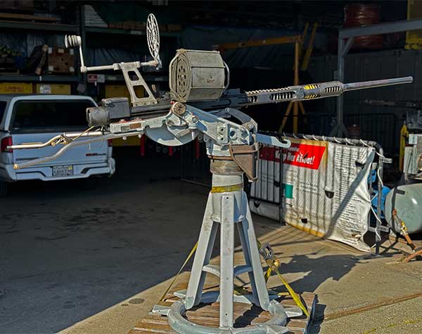
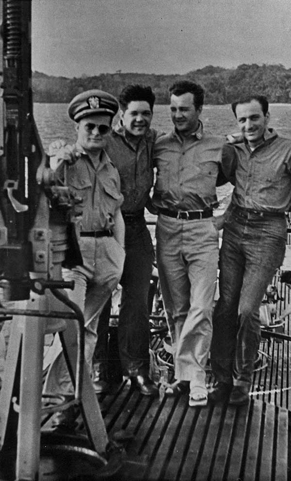
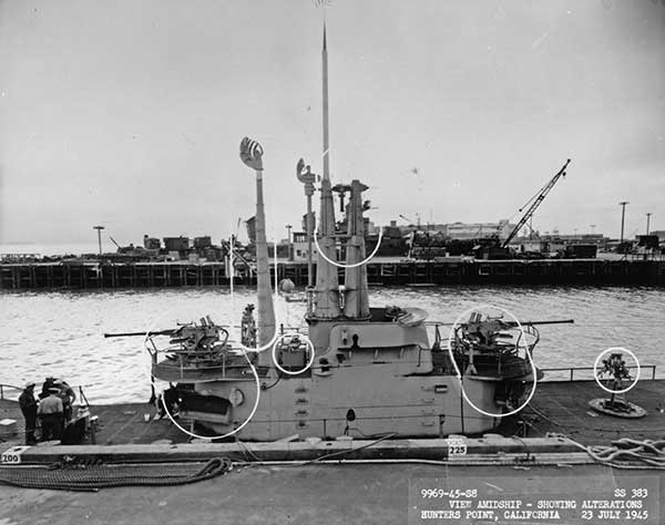
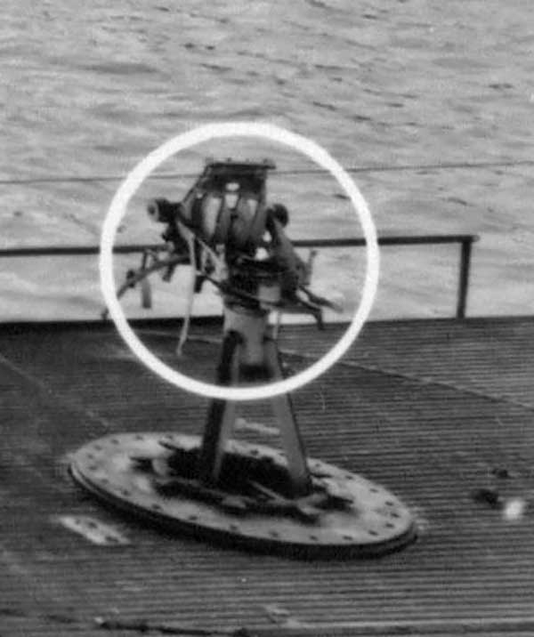
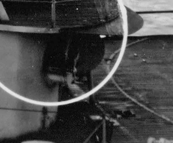
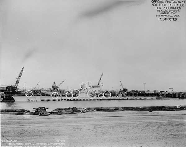
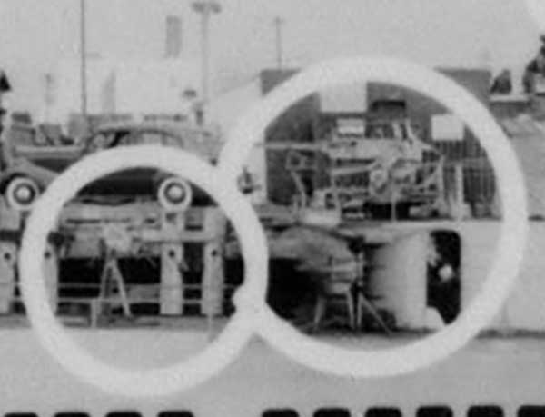
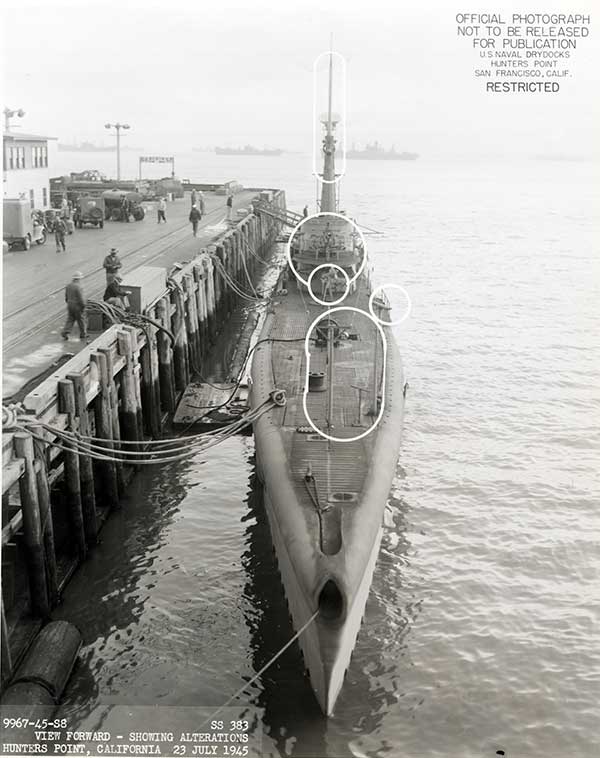
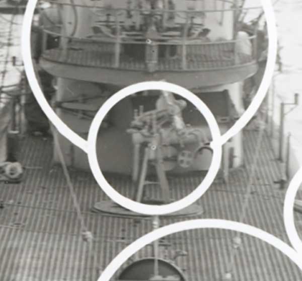
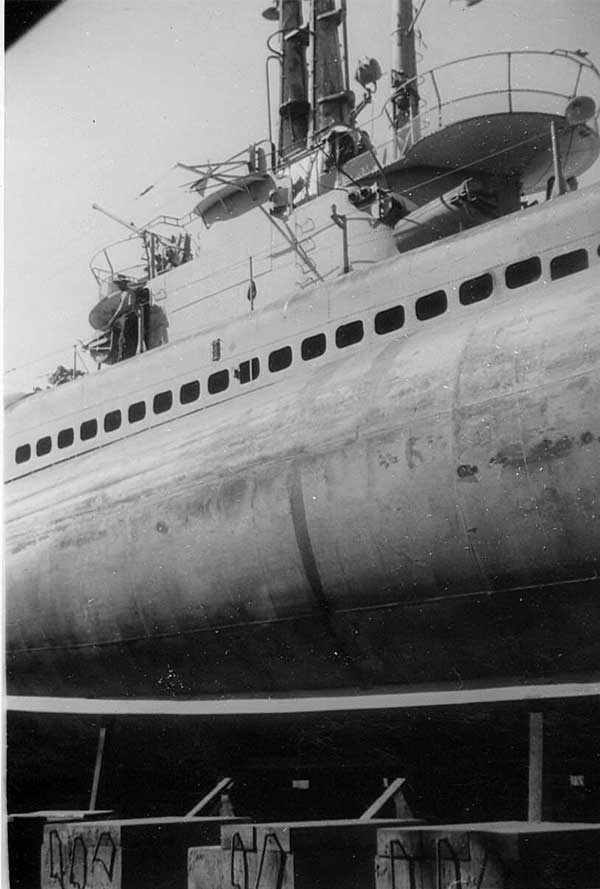
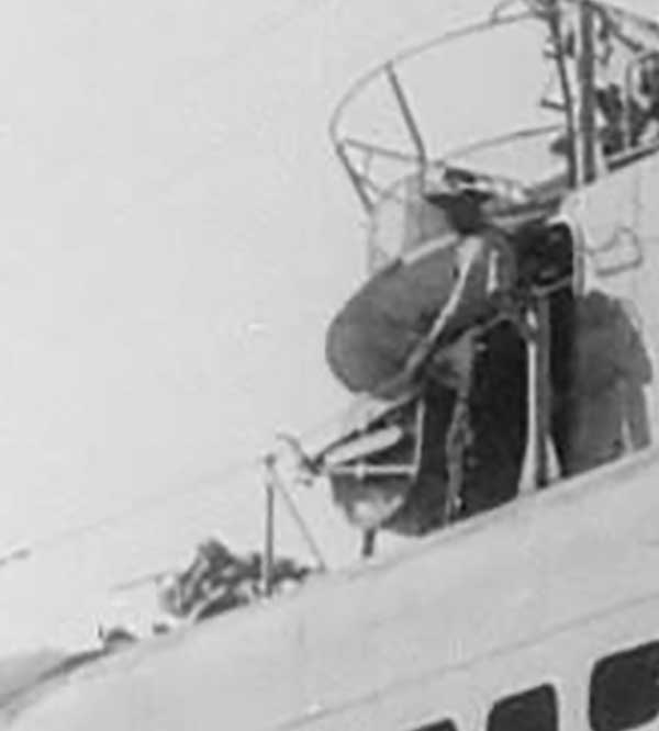
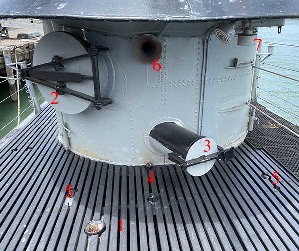
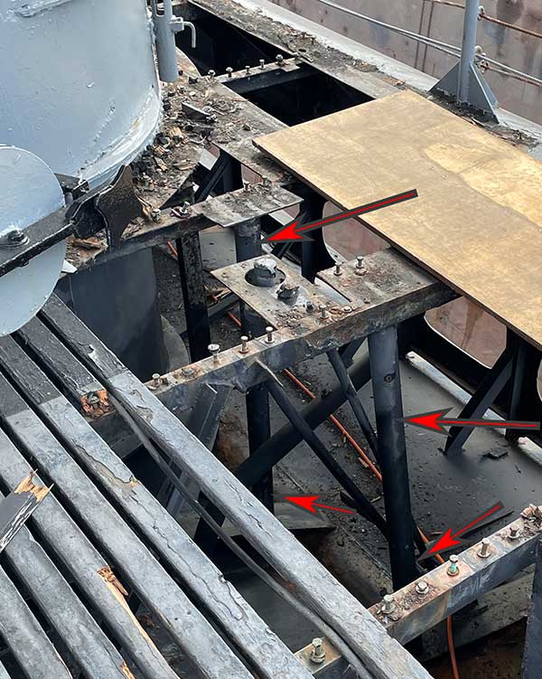
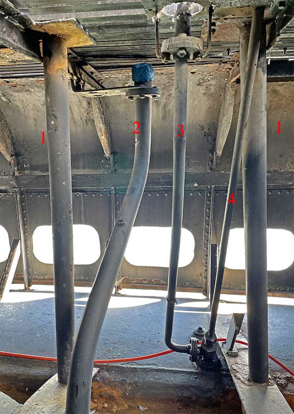
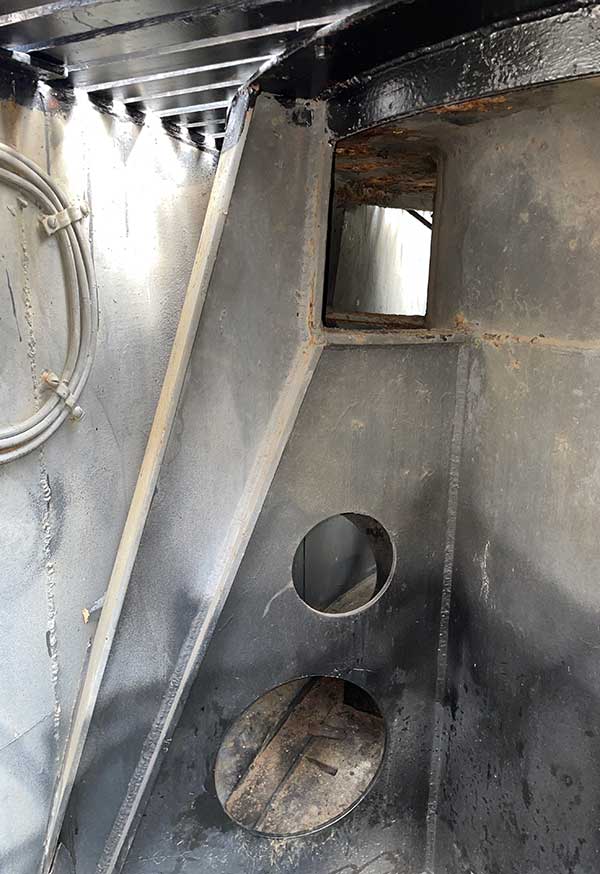
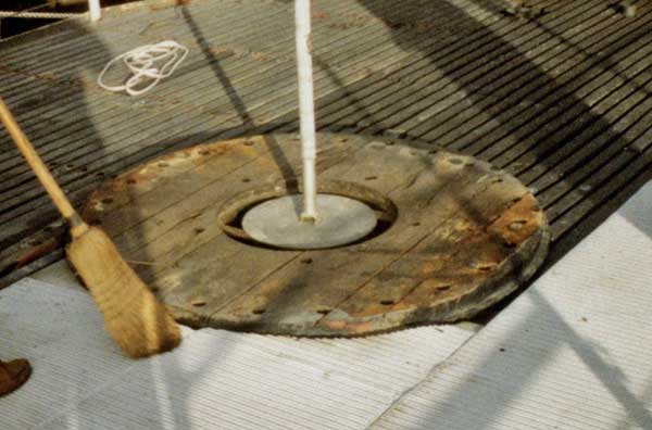
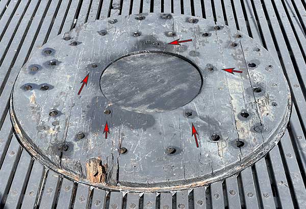
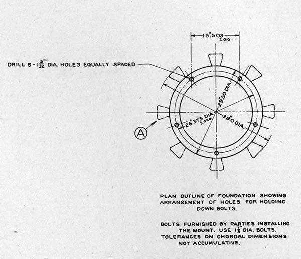
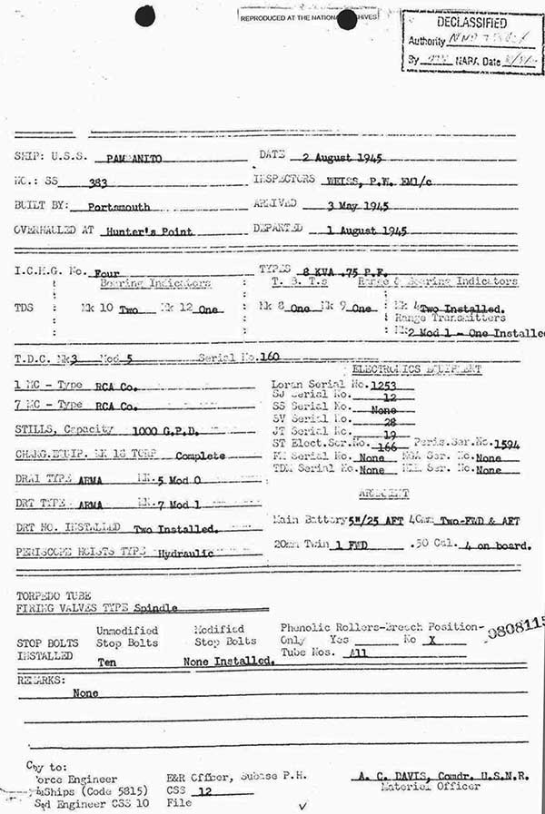
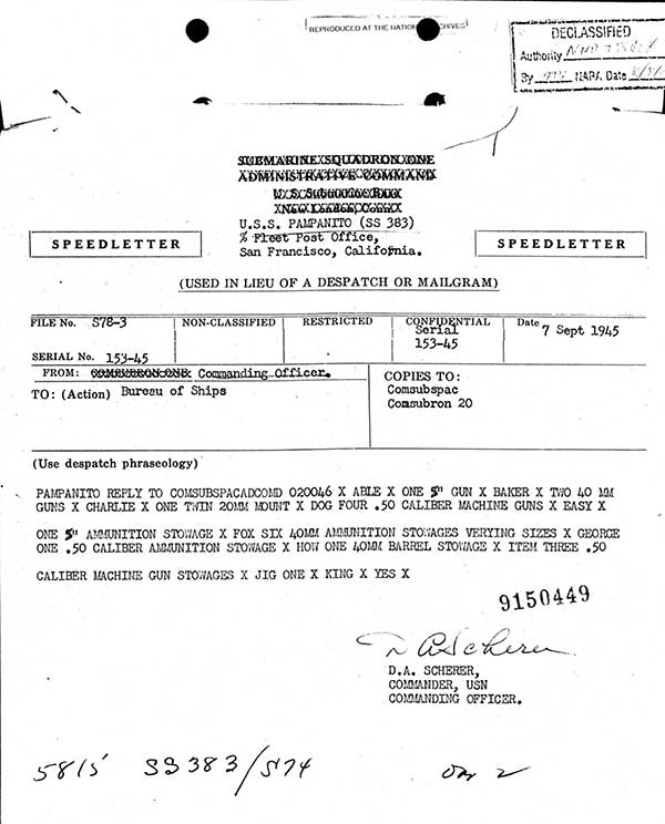
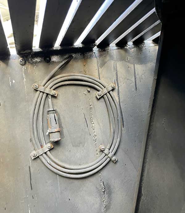
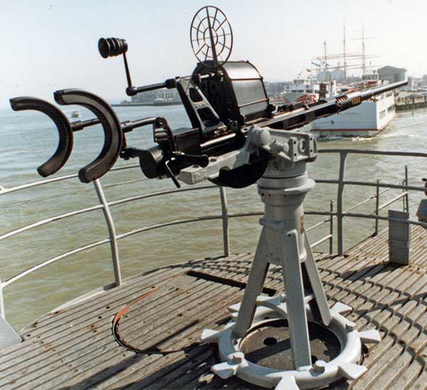
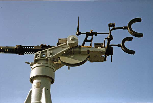
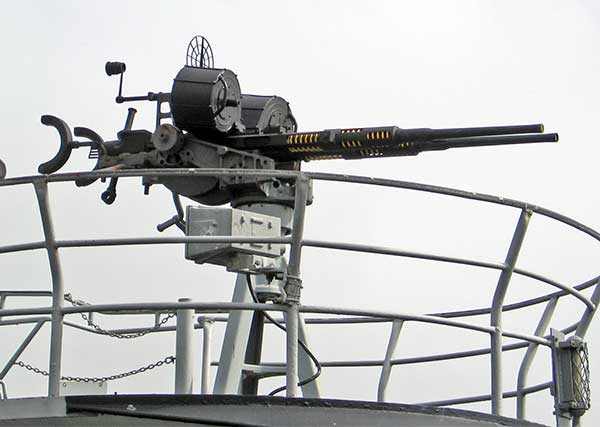
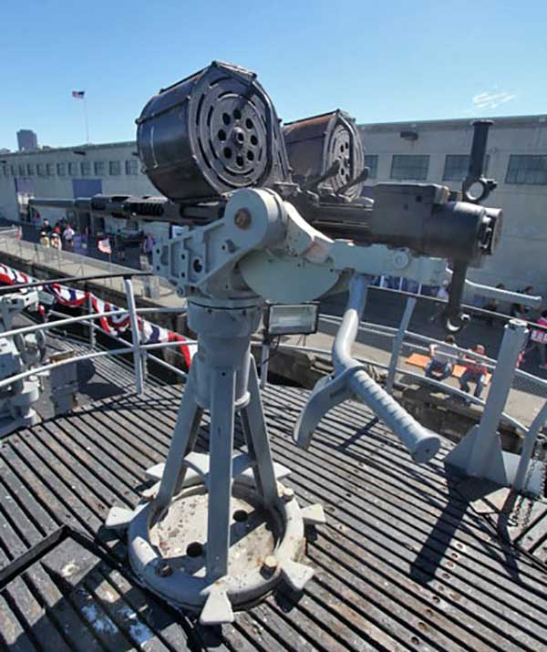
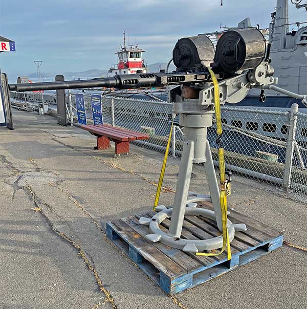
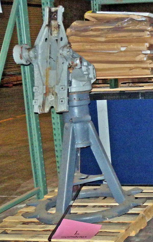
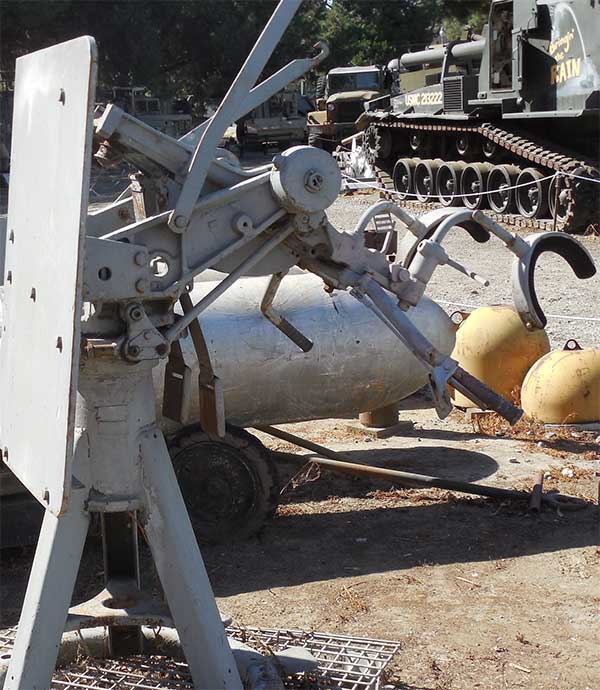
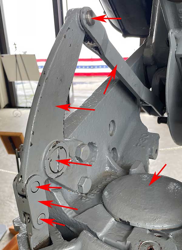
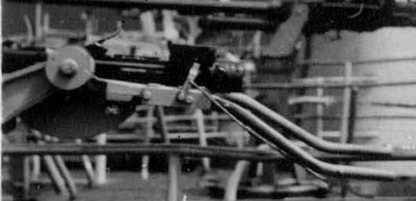
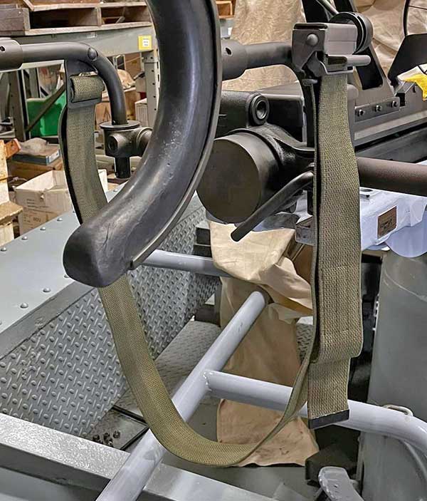 Buckle and shoulder strap on USS Texas mount.
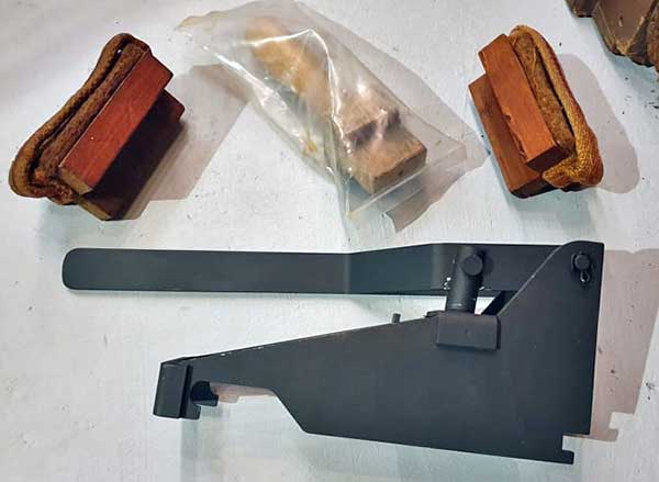
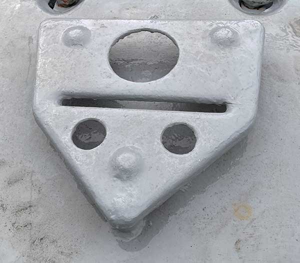
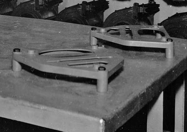
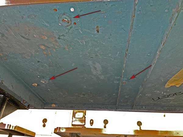
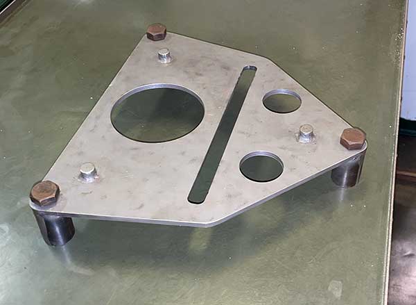
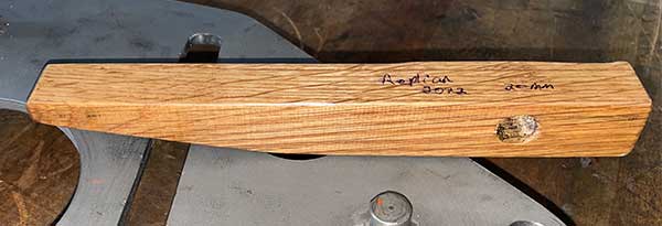
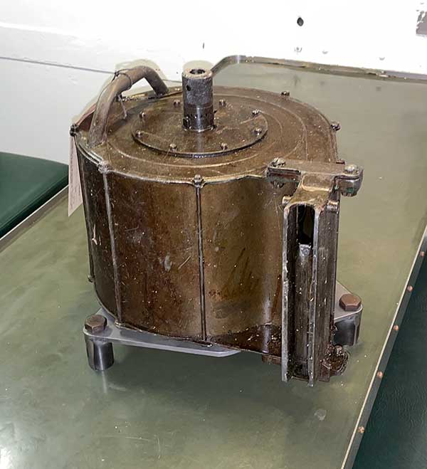
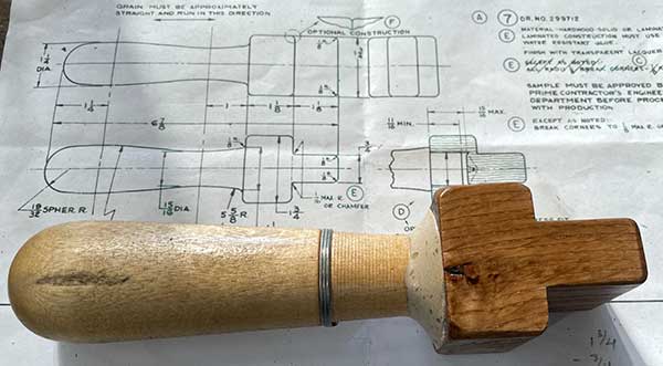
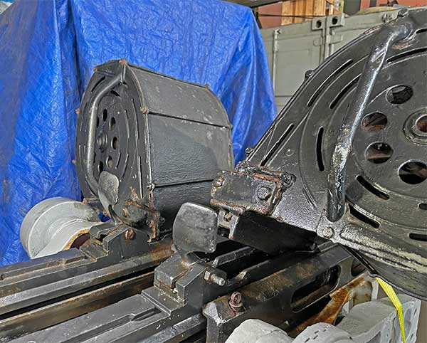
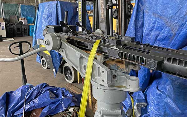
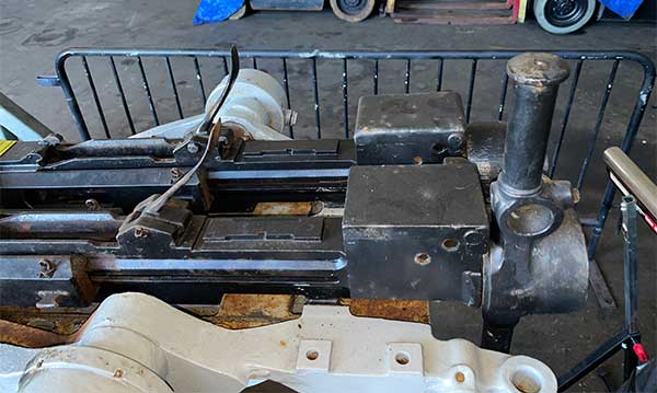
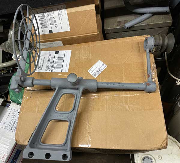
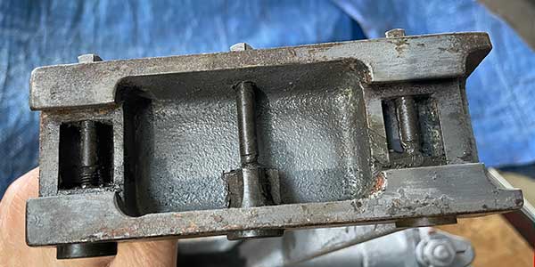
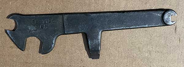
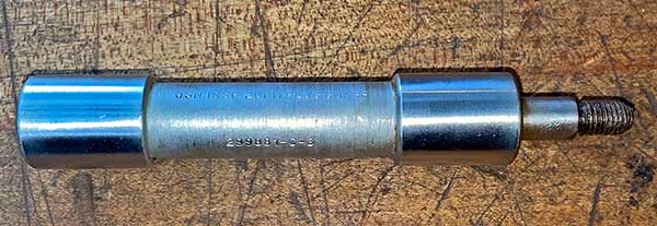
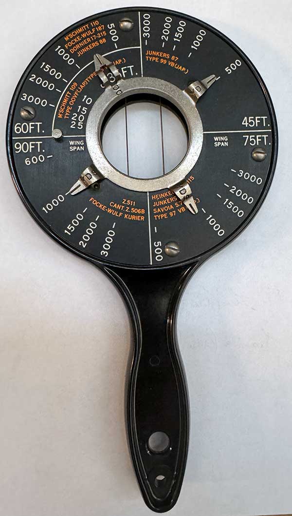
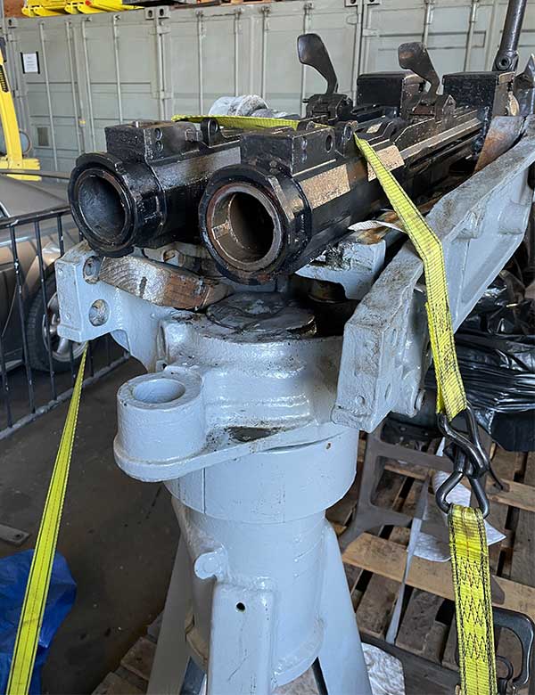
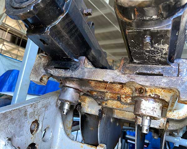
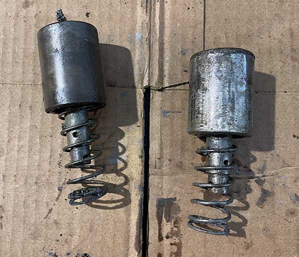
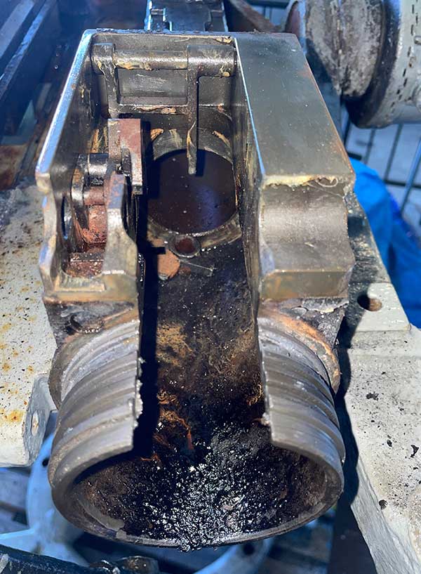
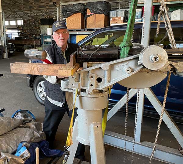
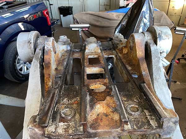
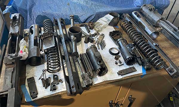
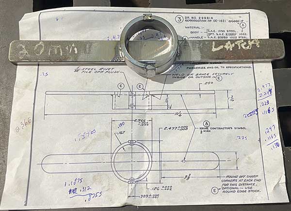
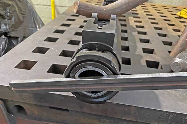
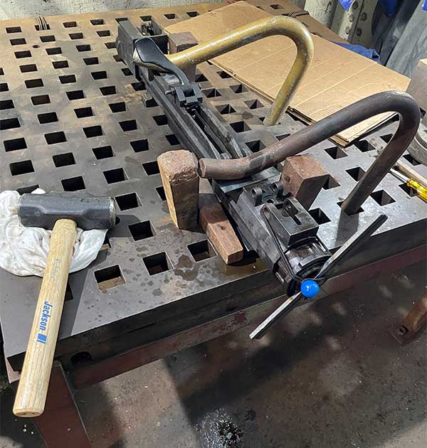
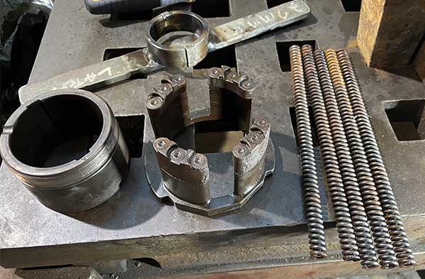
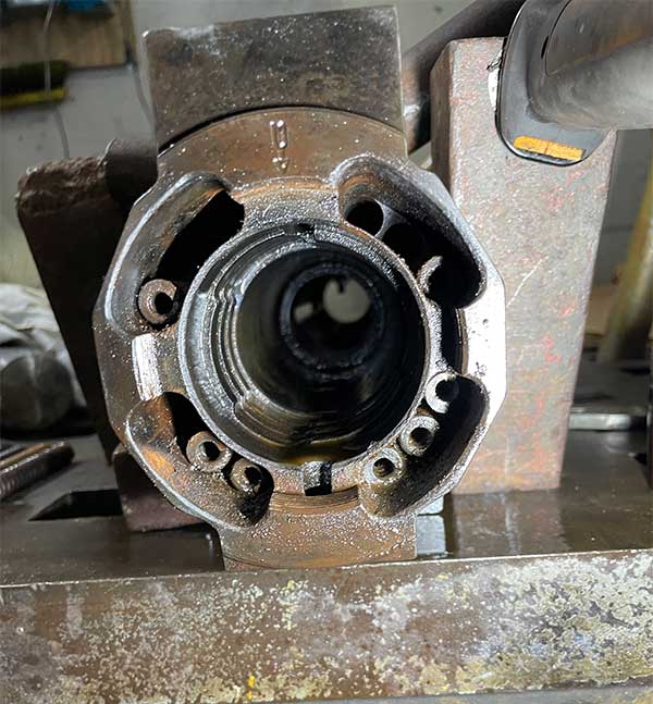
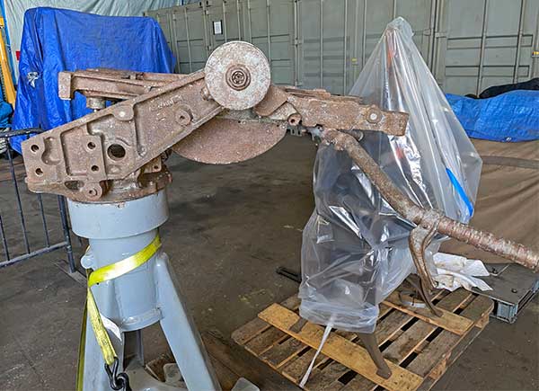
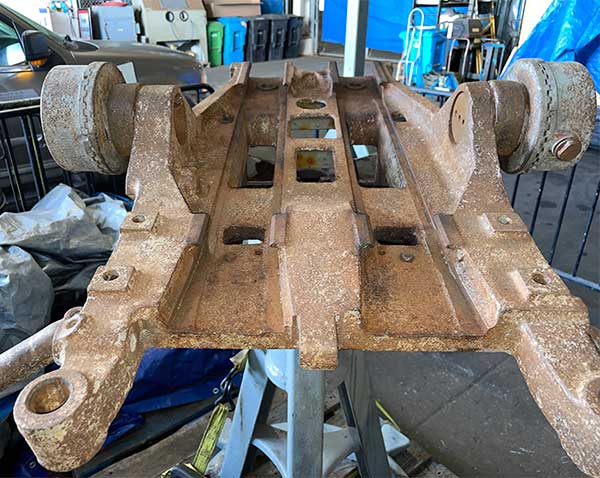
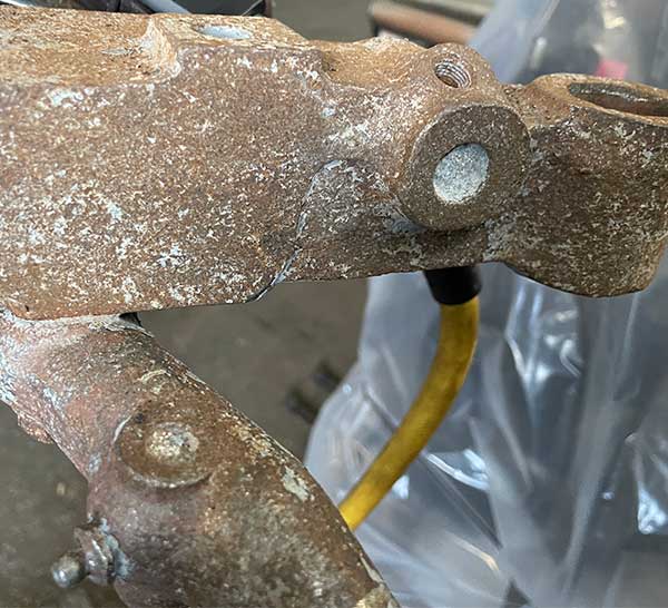
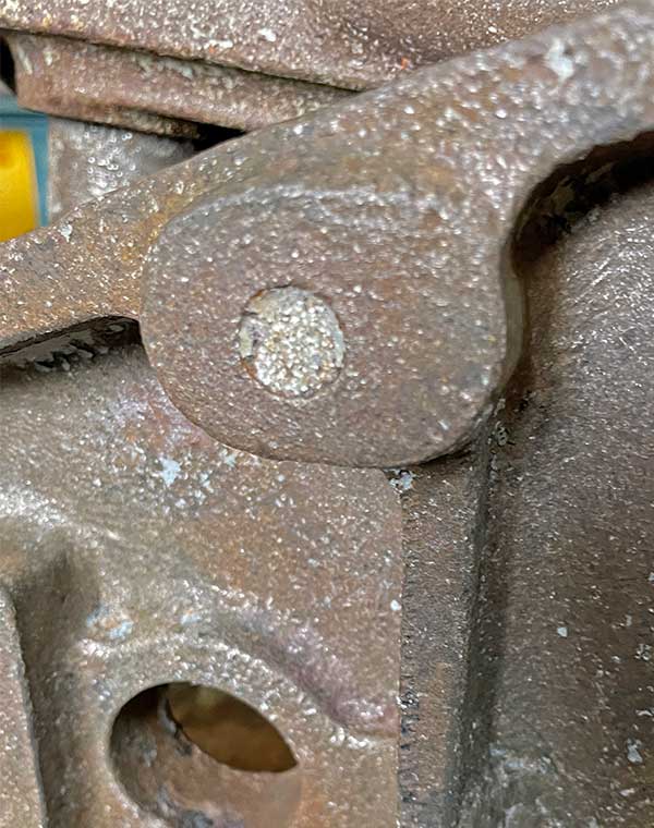
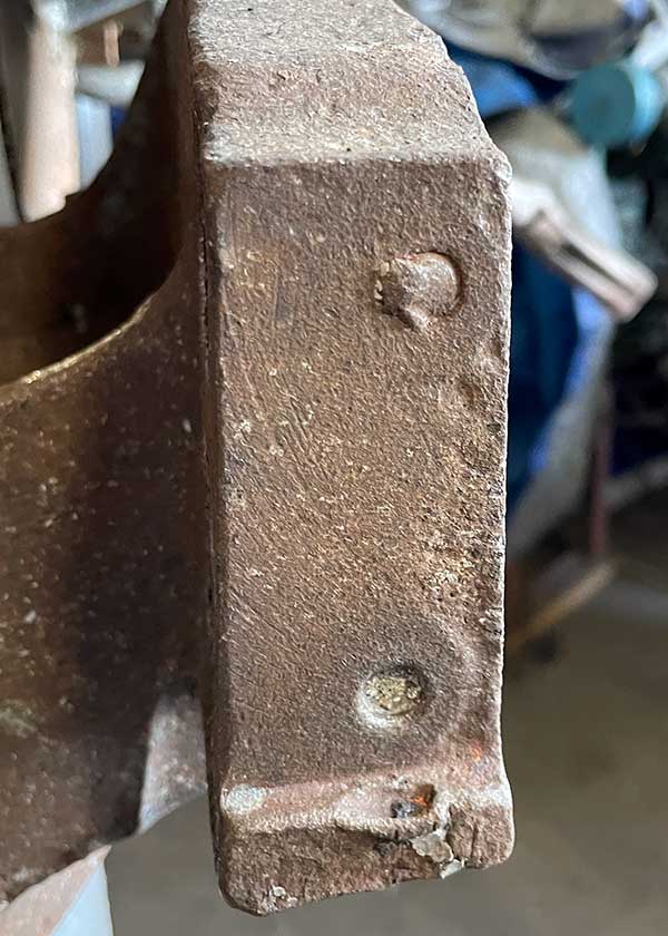
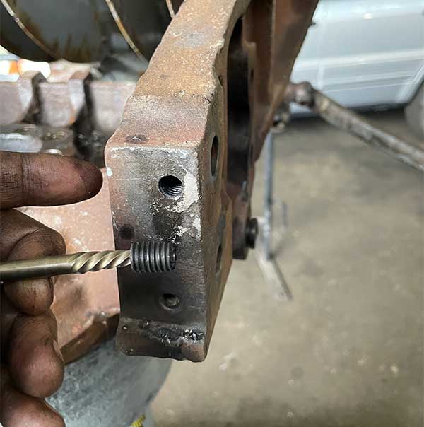
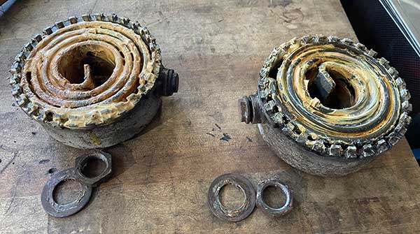
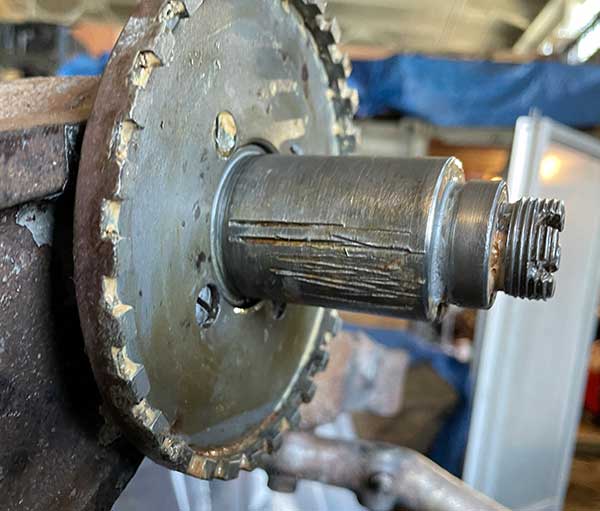
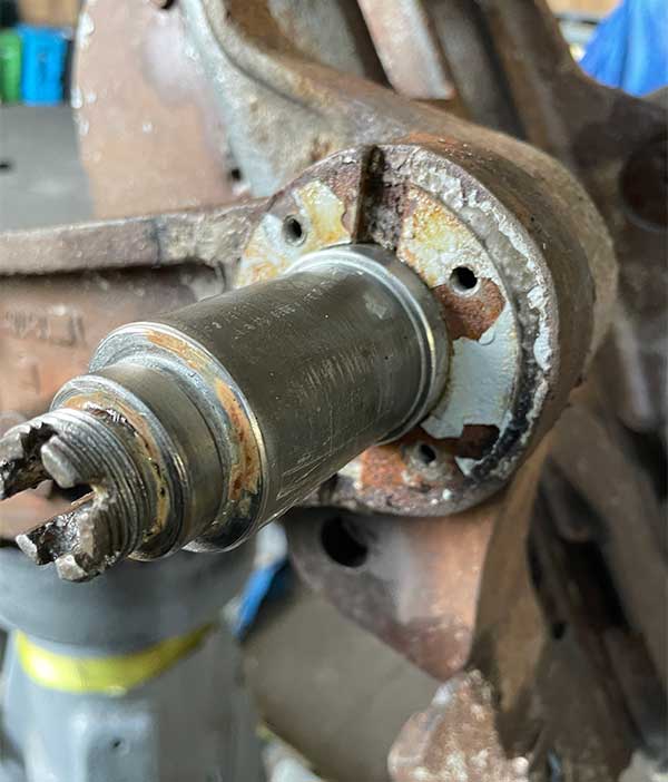
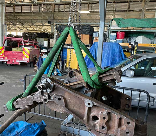
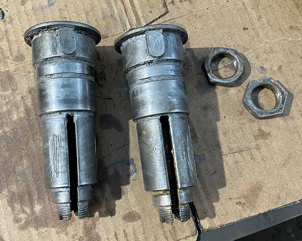
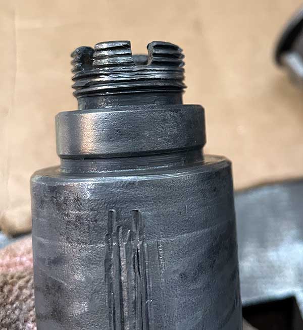
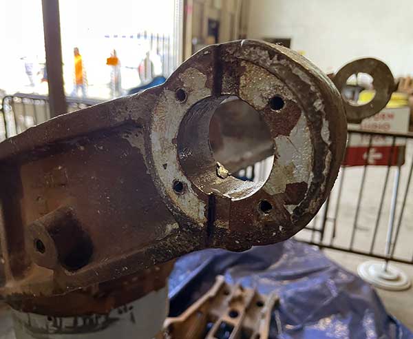
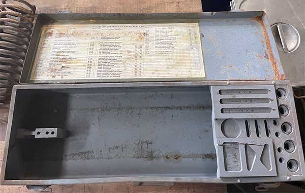
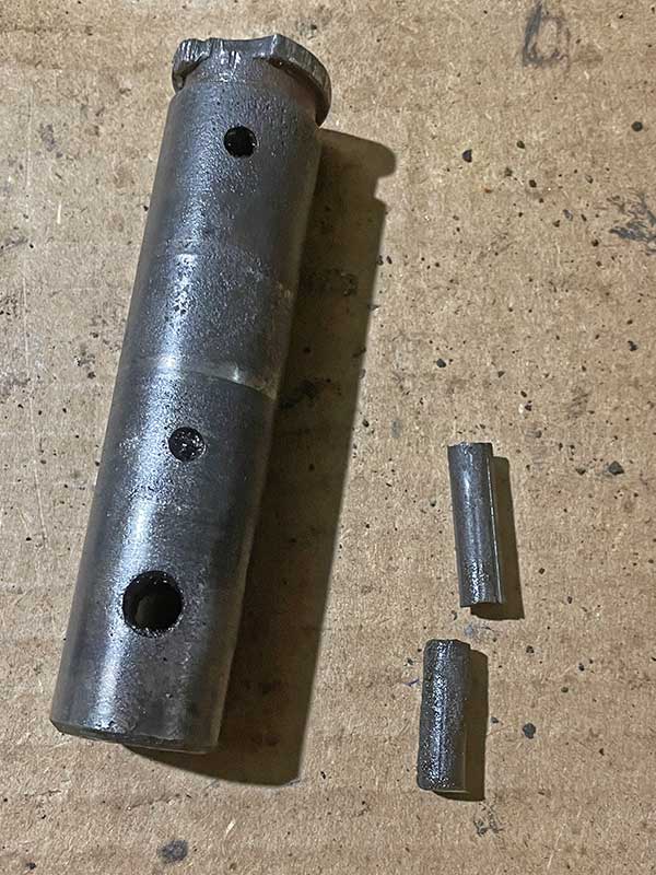
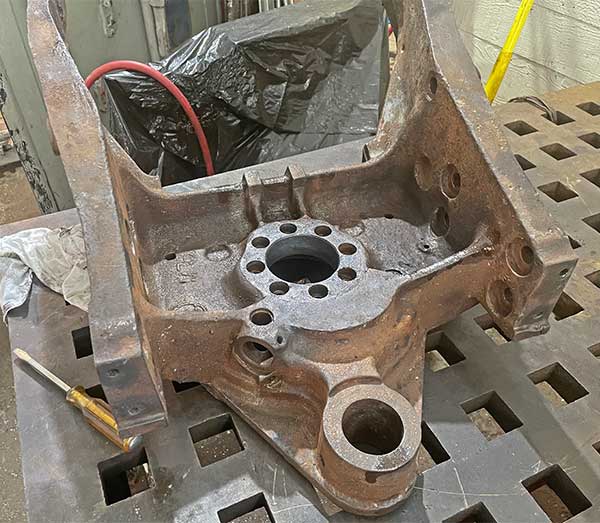
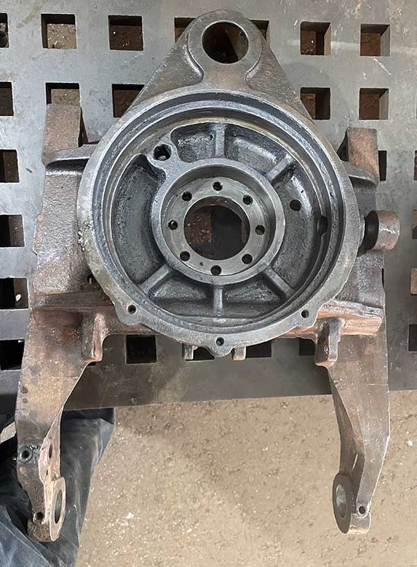
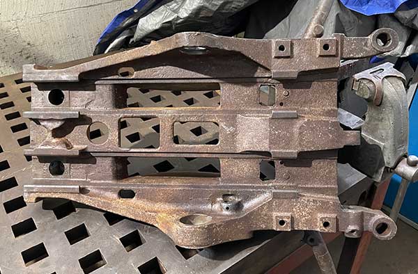
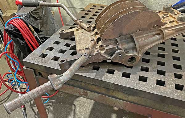
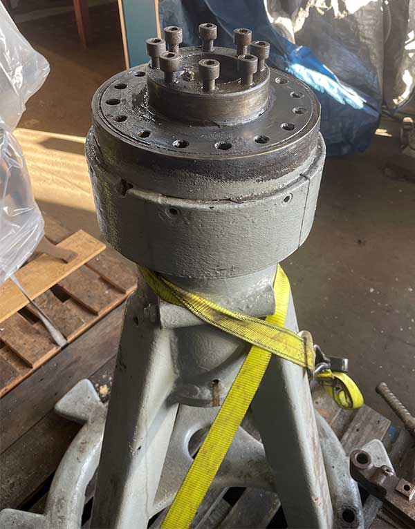
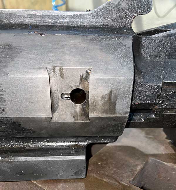
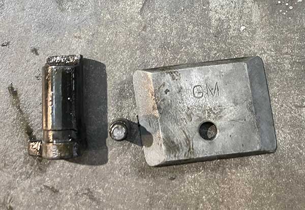
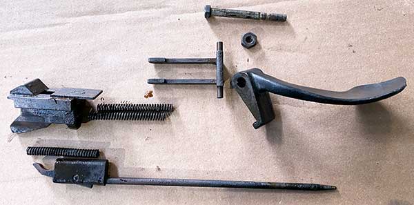
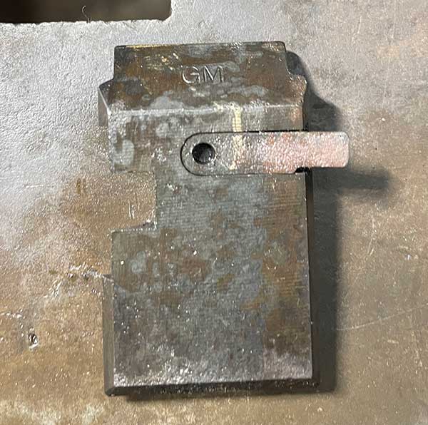
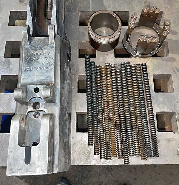
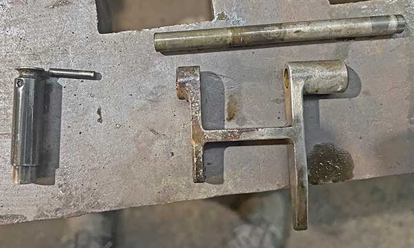
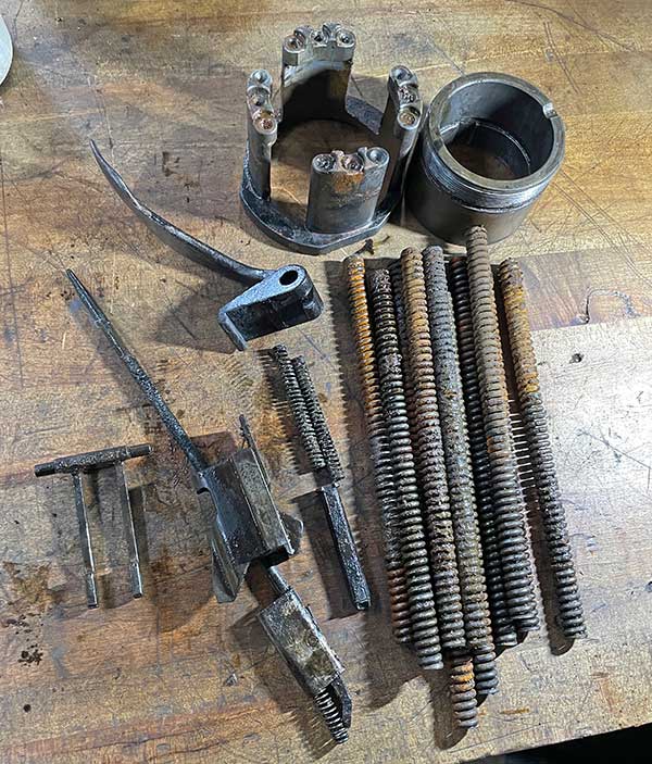
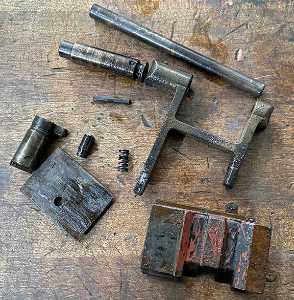
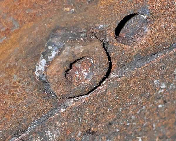
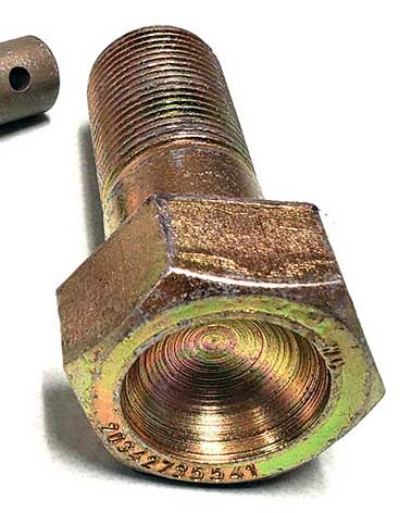
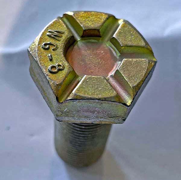
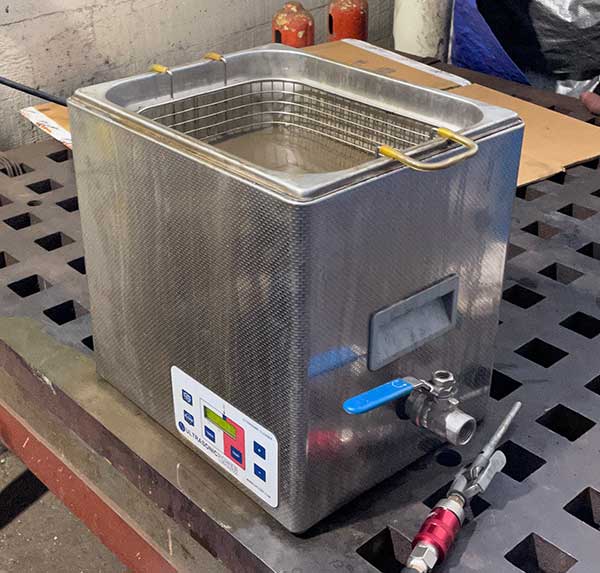
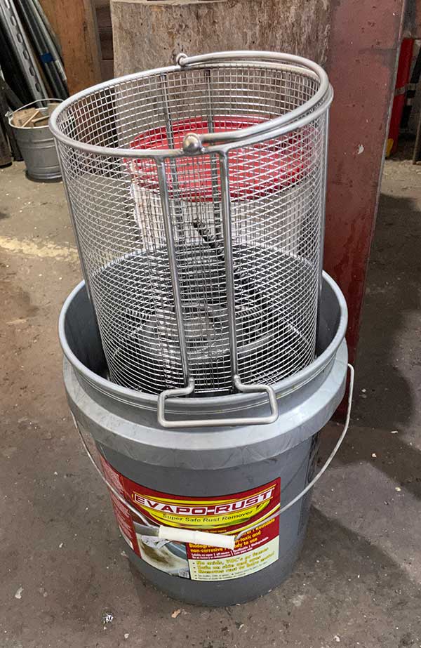
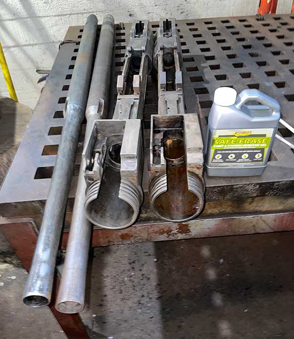
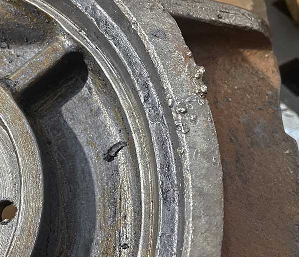
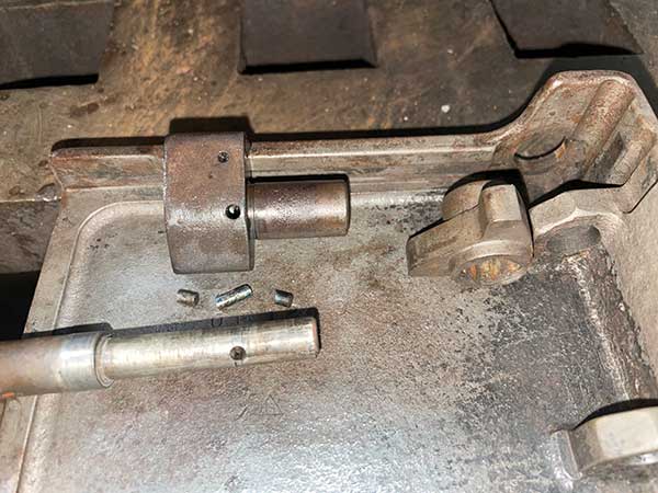
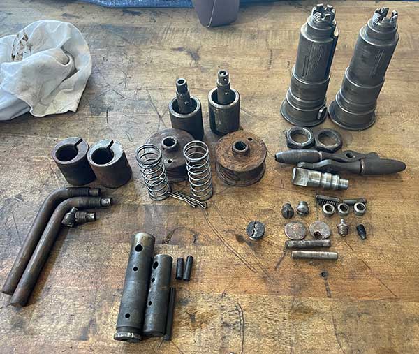
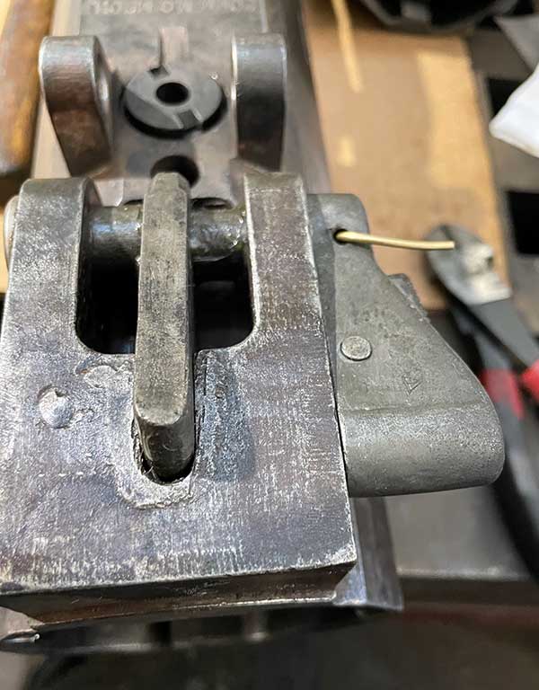
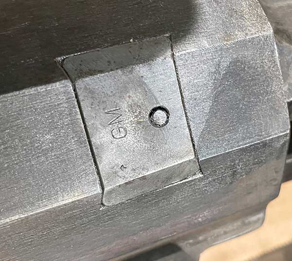
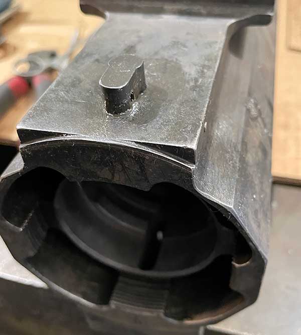
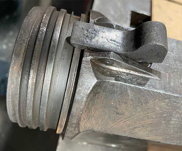
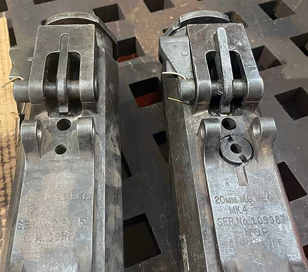
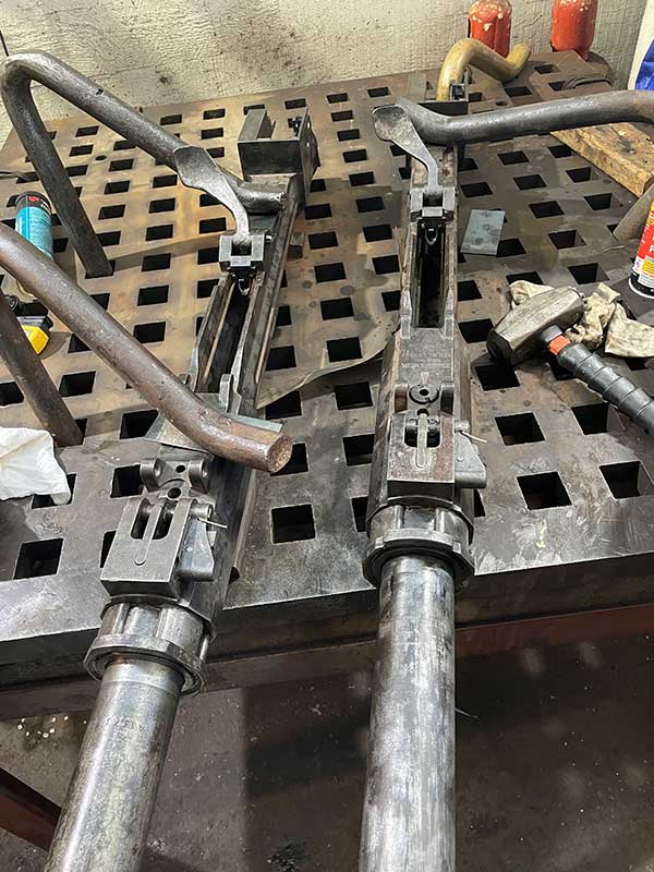
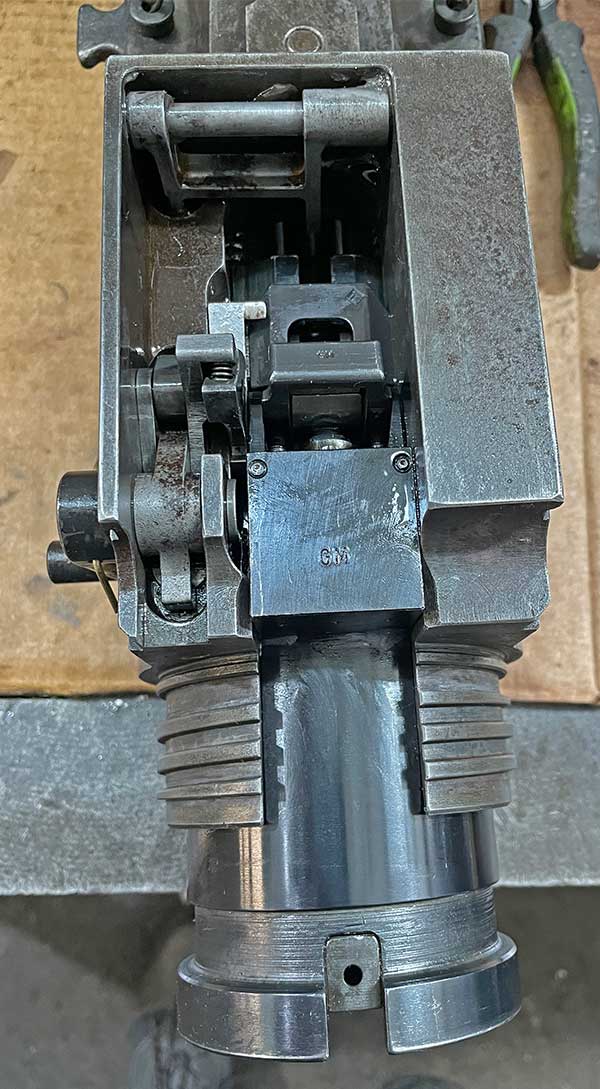
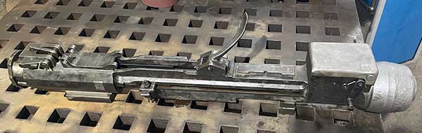
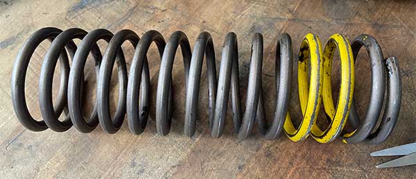
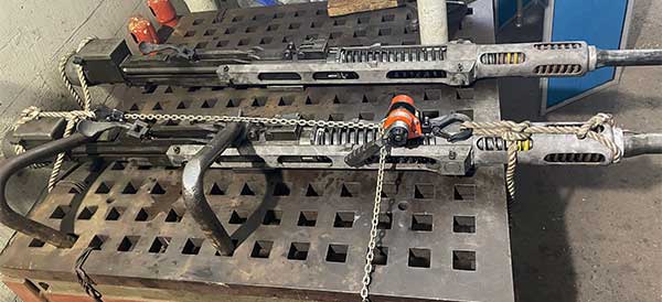
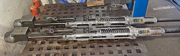
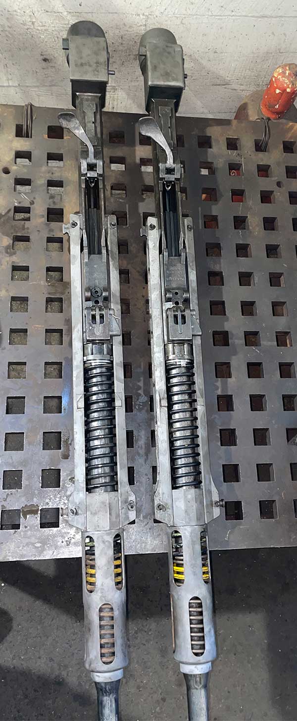
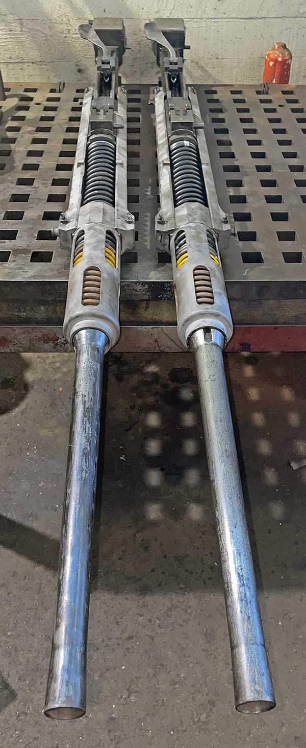
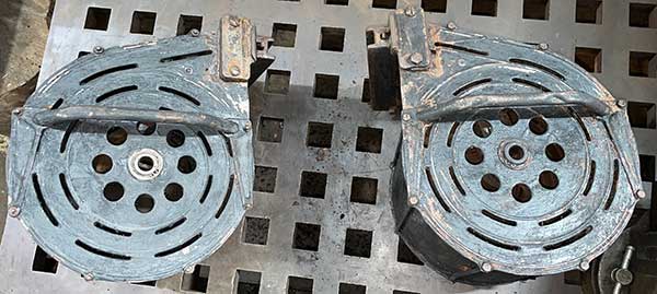
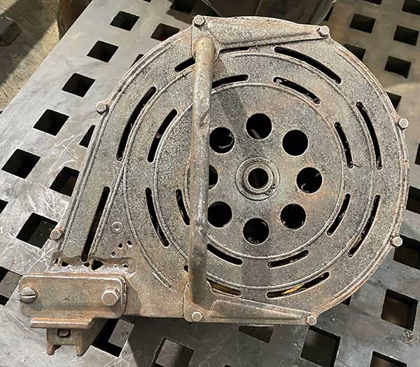
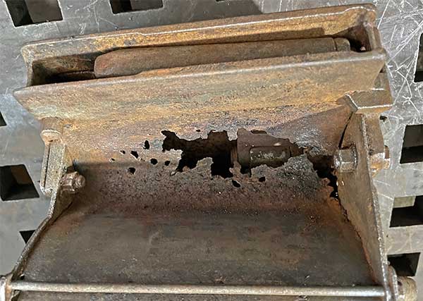
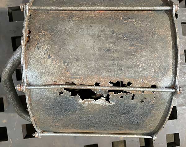
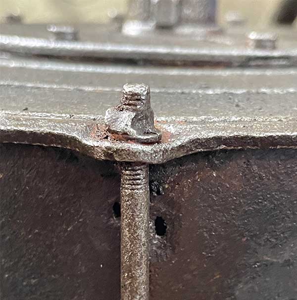 2 Jun 2022. Right magazine, wasted nut.
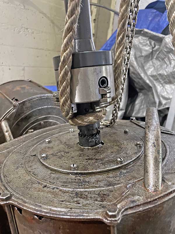
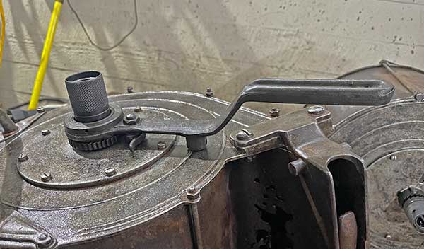
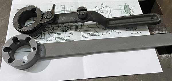
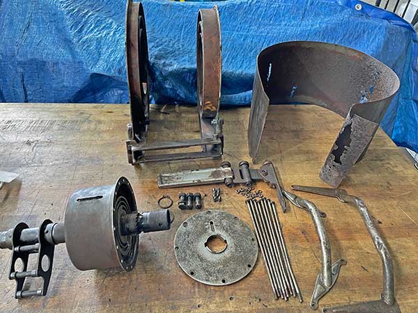
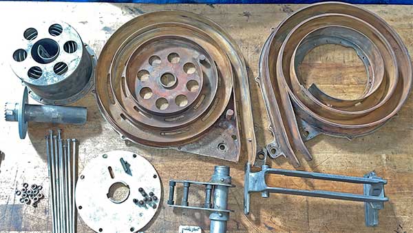
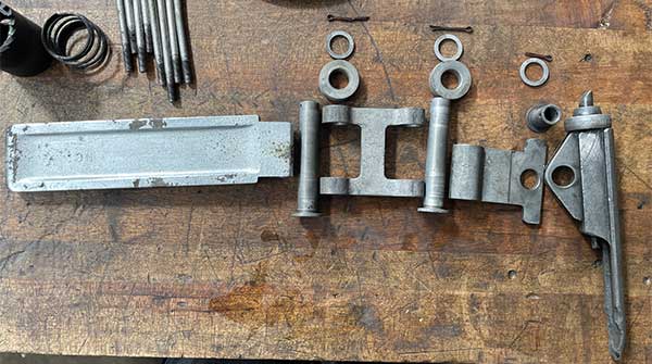
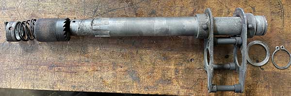
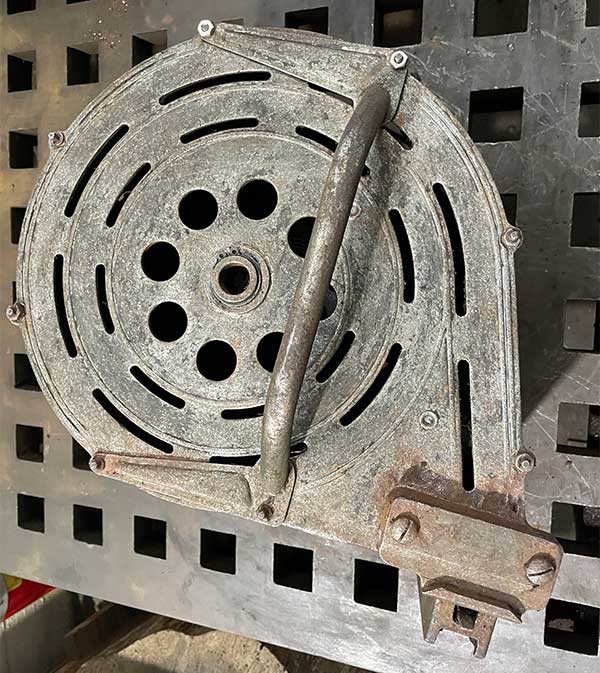
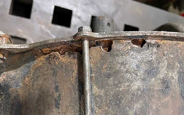
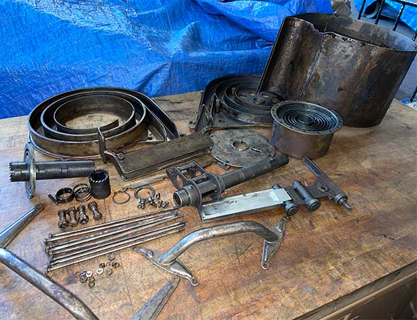
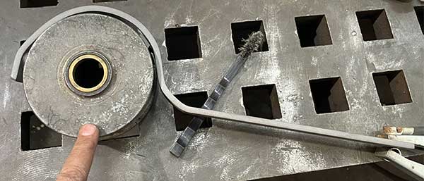
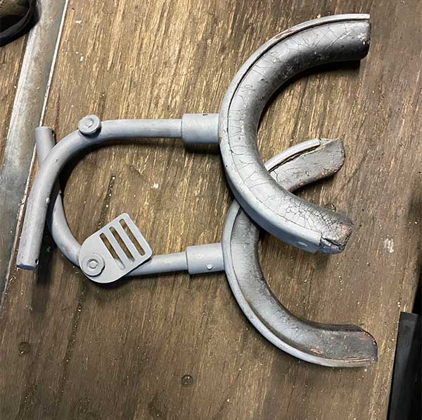
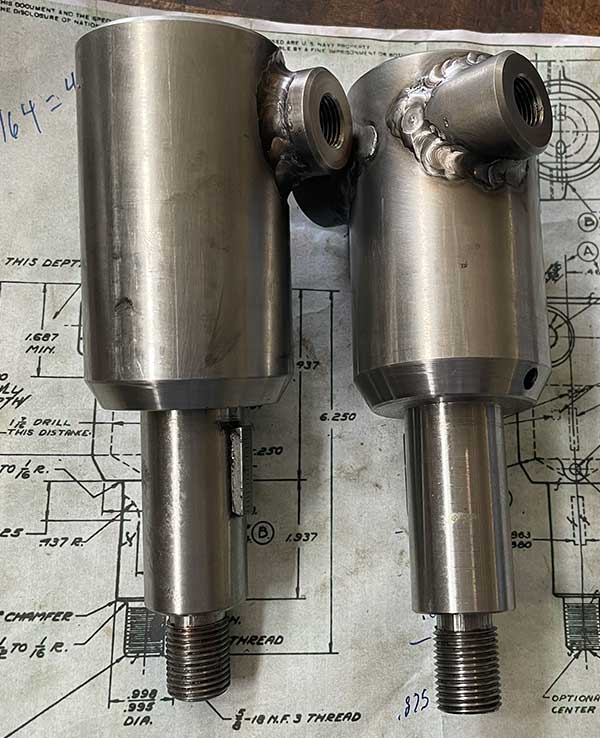
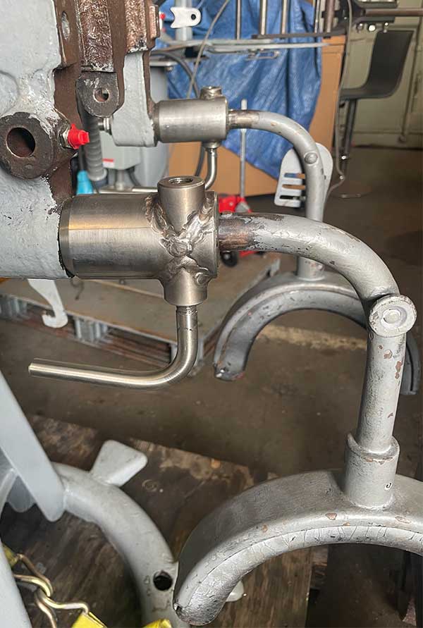
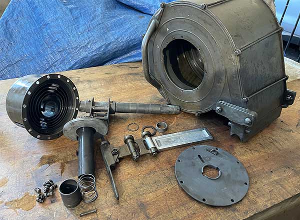
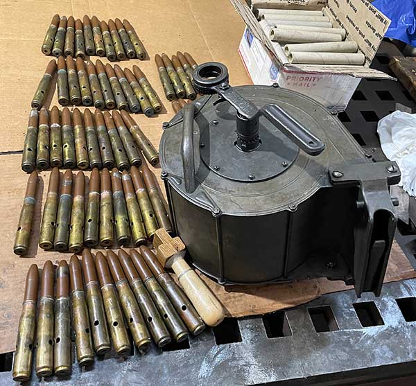
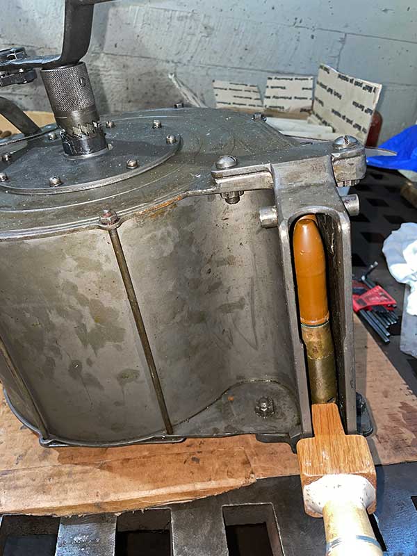
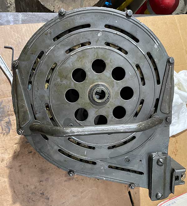
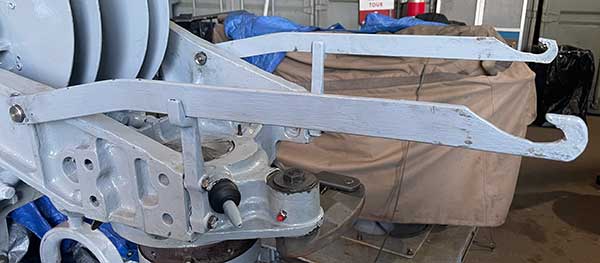
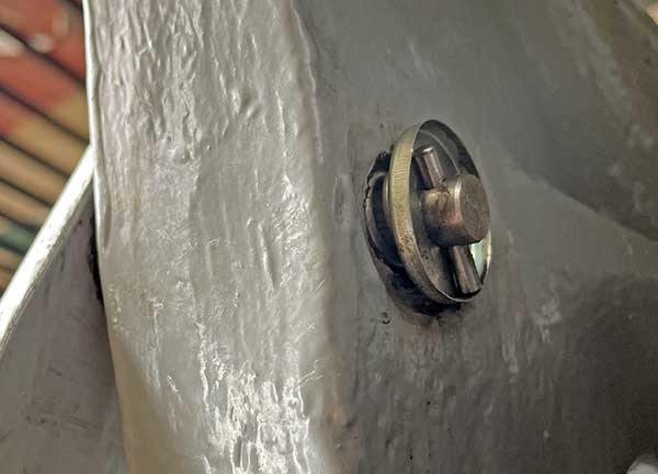
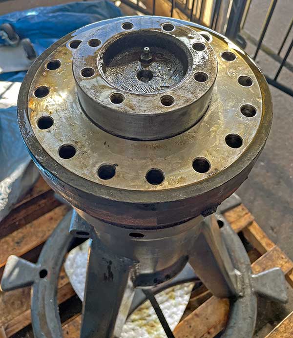
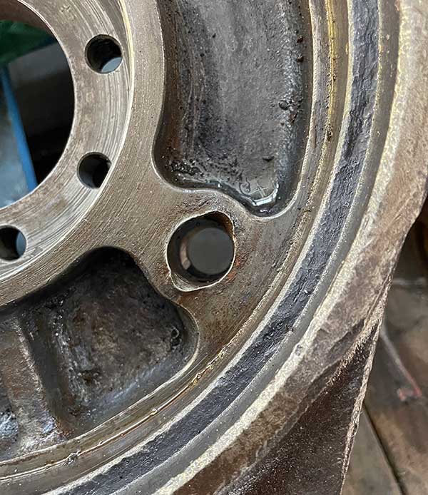
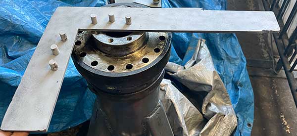
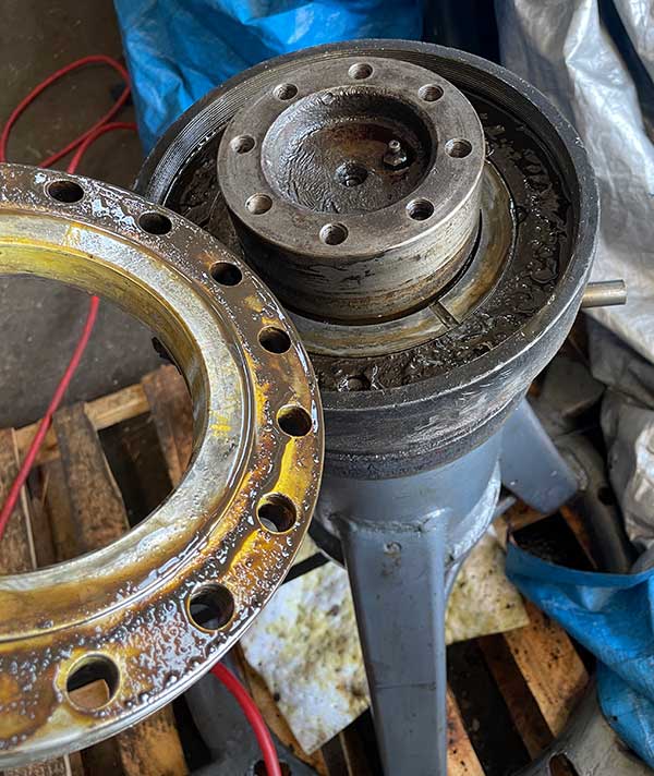
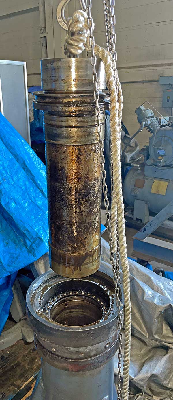
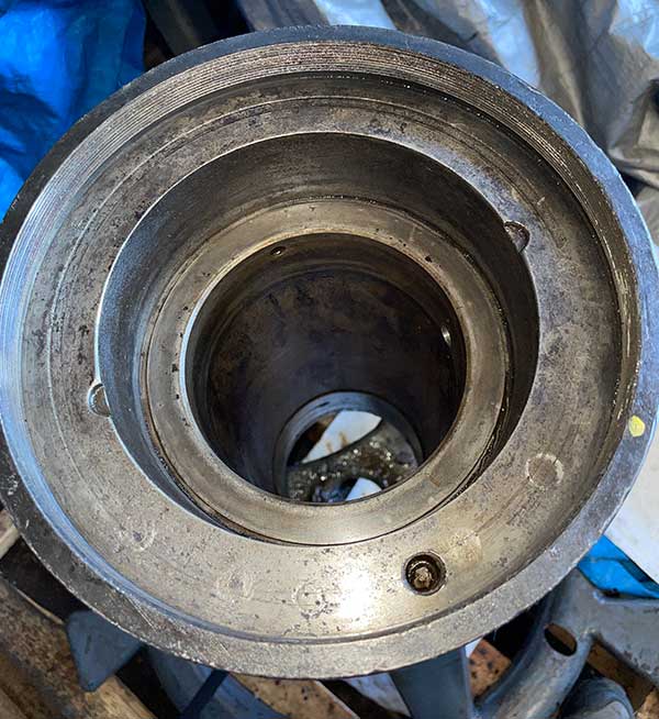
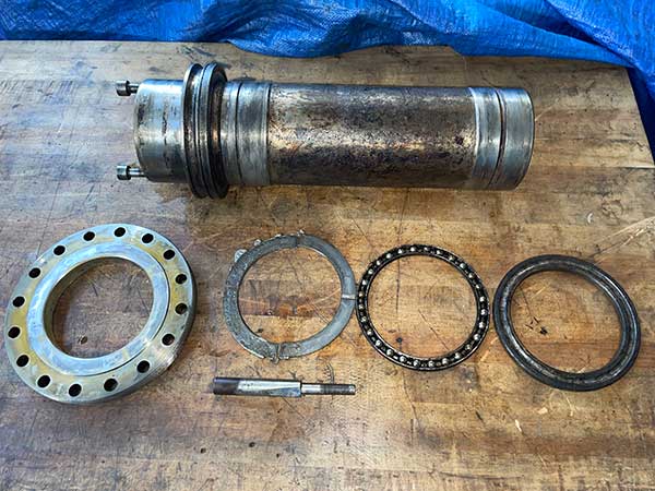
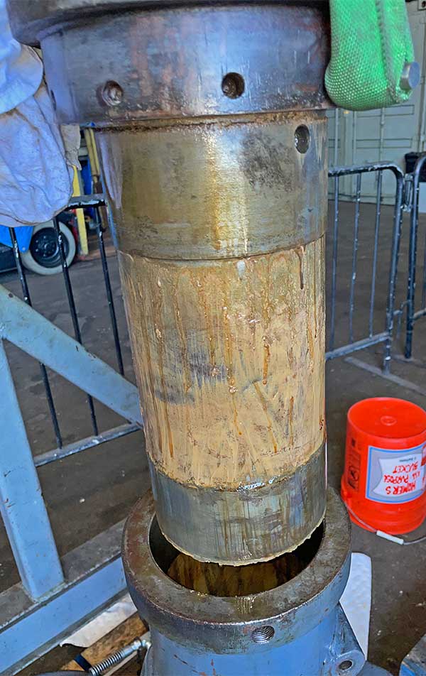
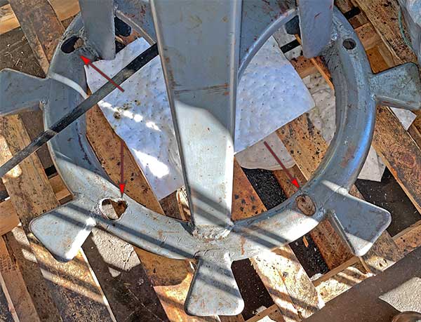
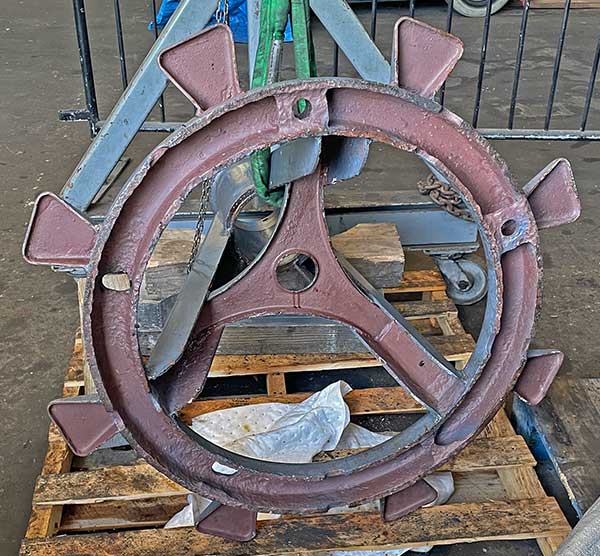
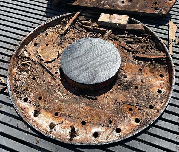
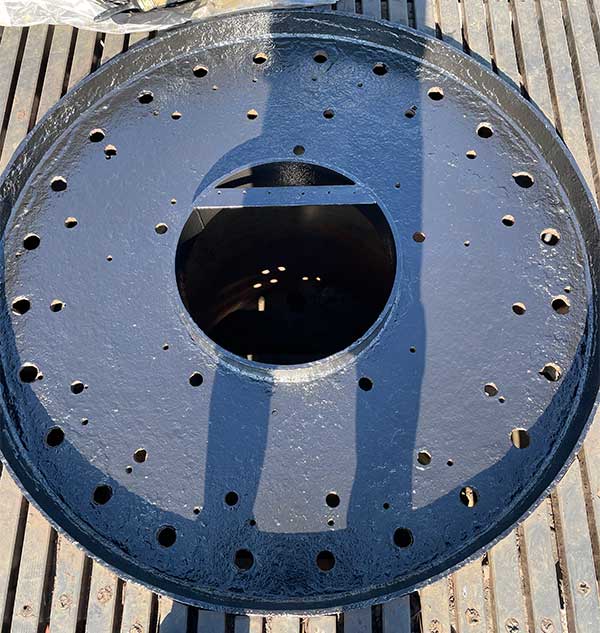
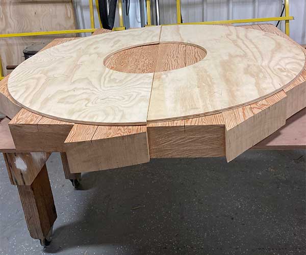
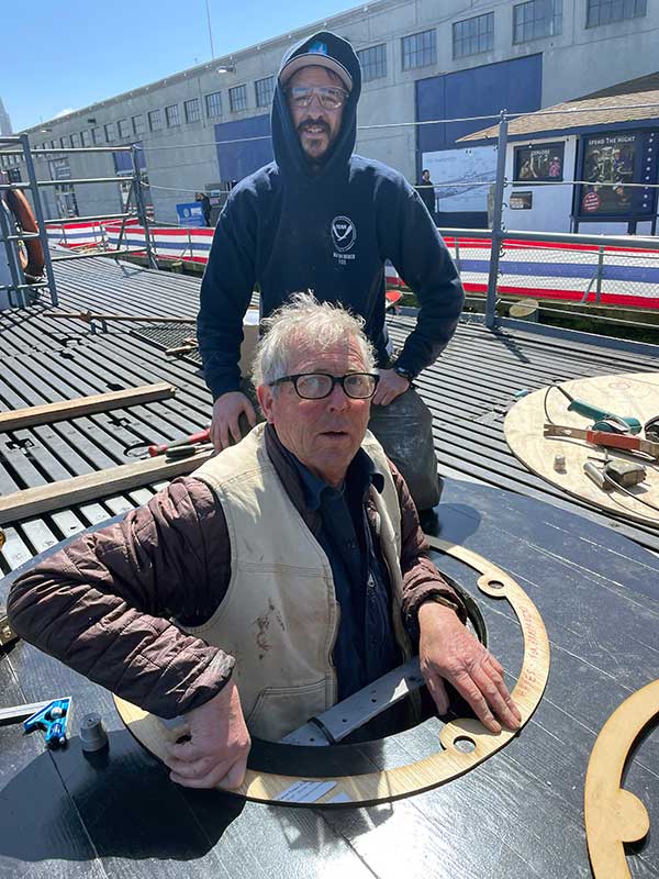
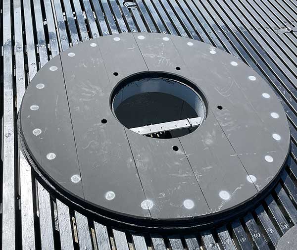
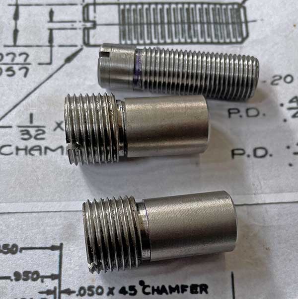
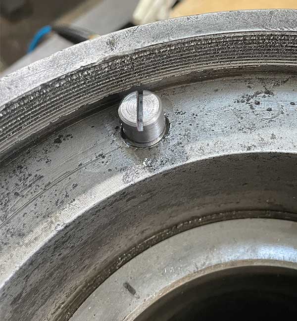
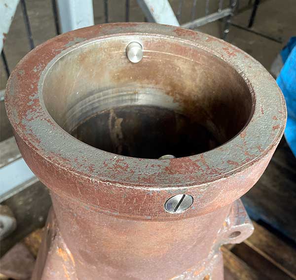
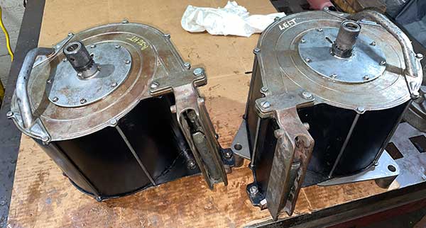
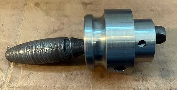
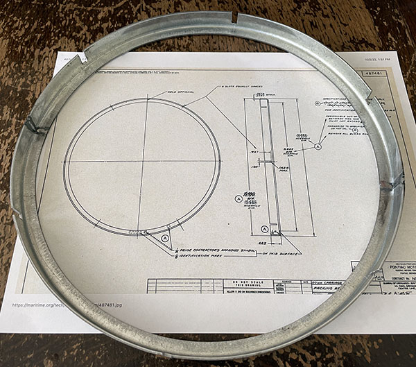
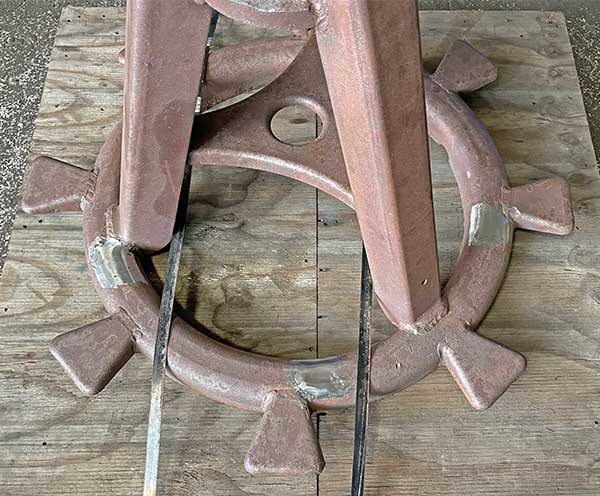
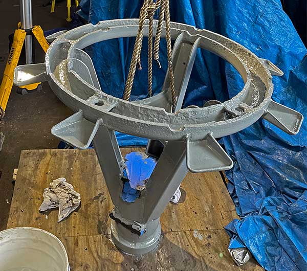
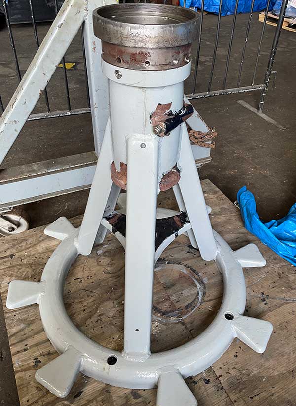
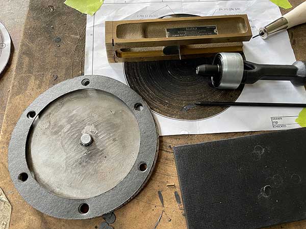
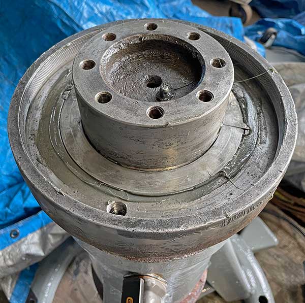
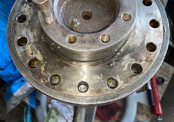
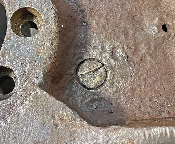
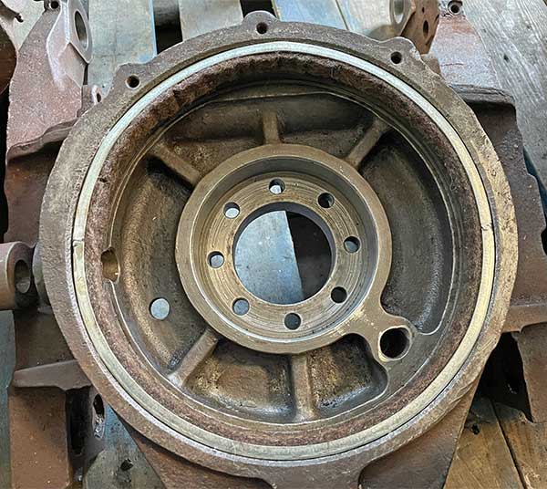
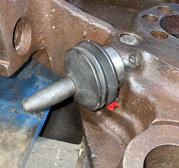
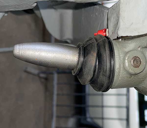
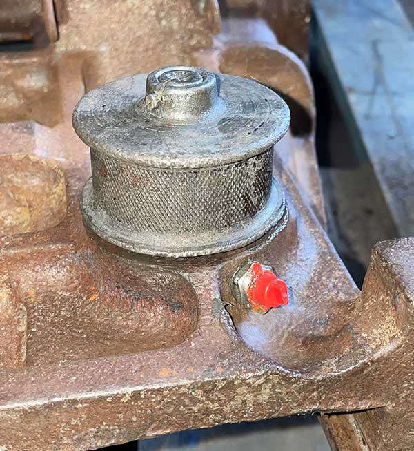
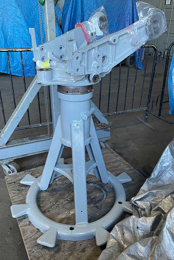
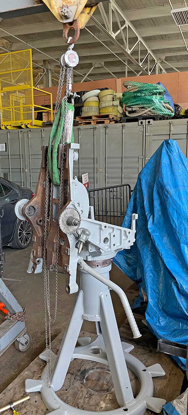
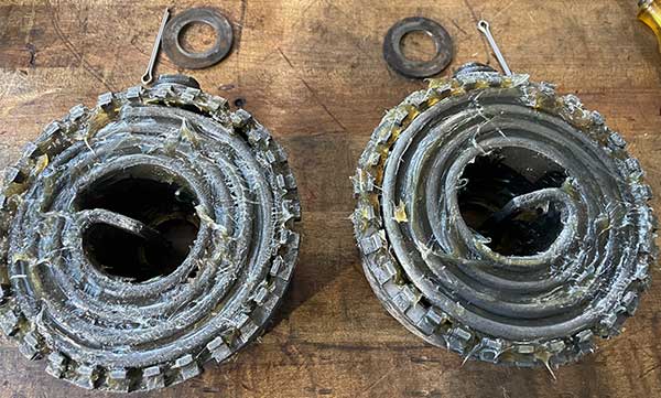
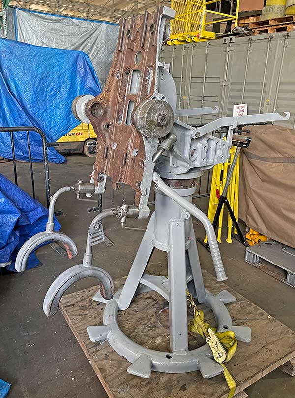
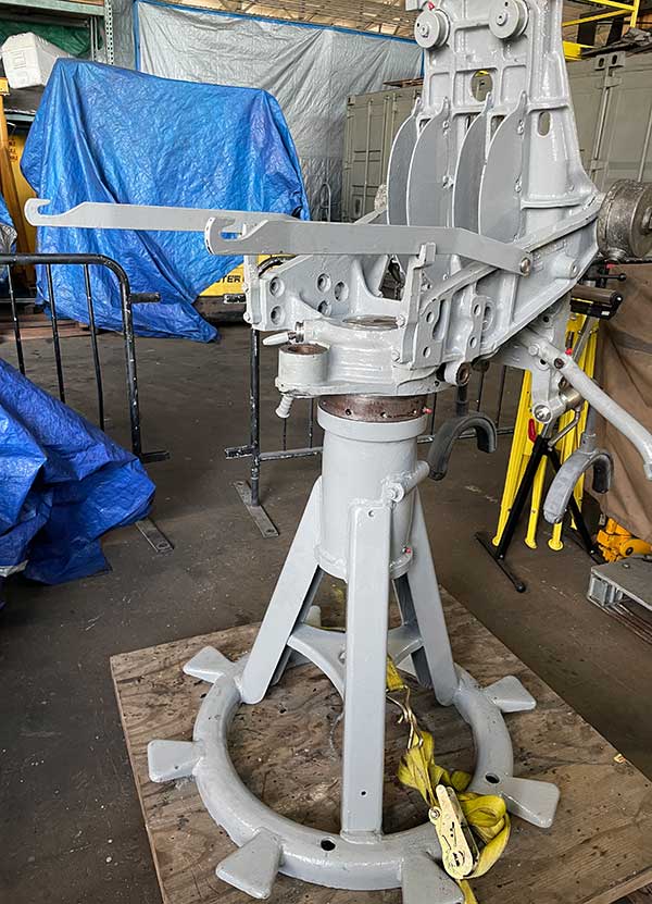
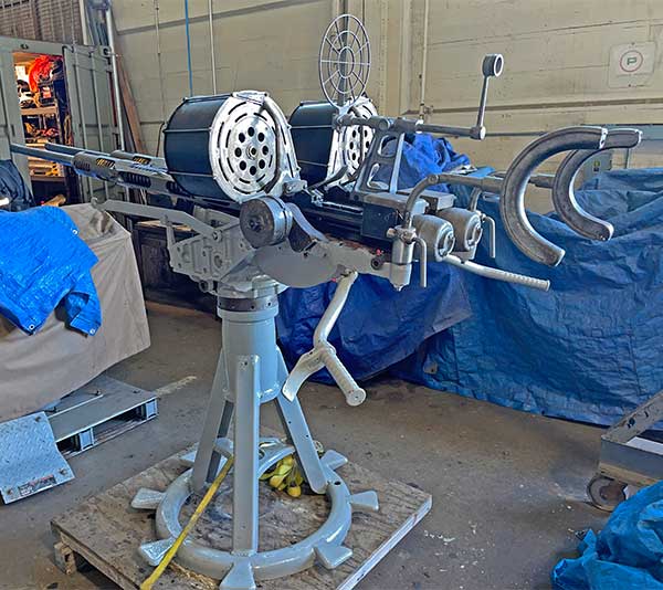
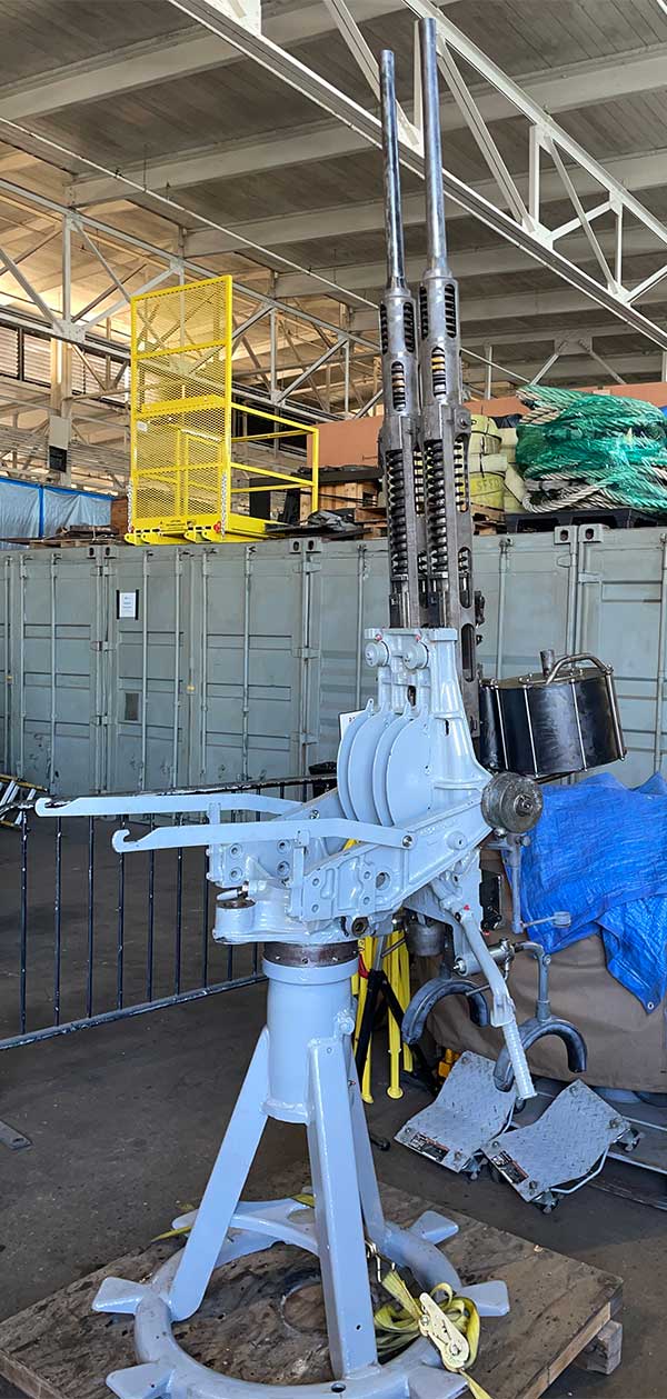
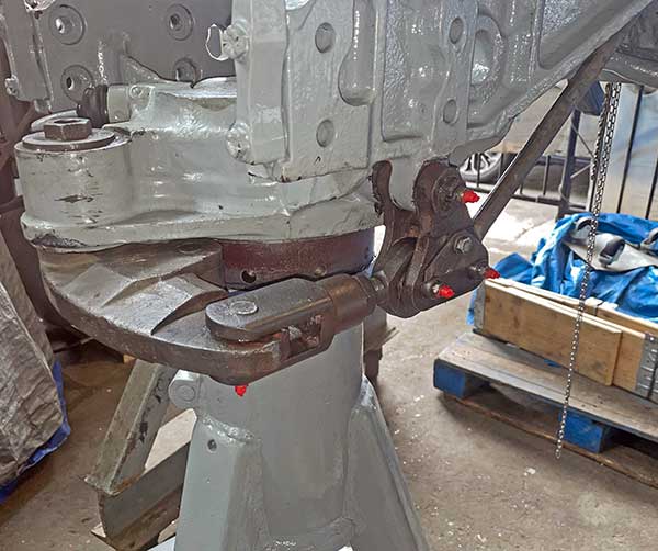
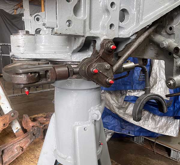
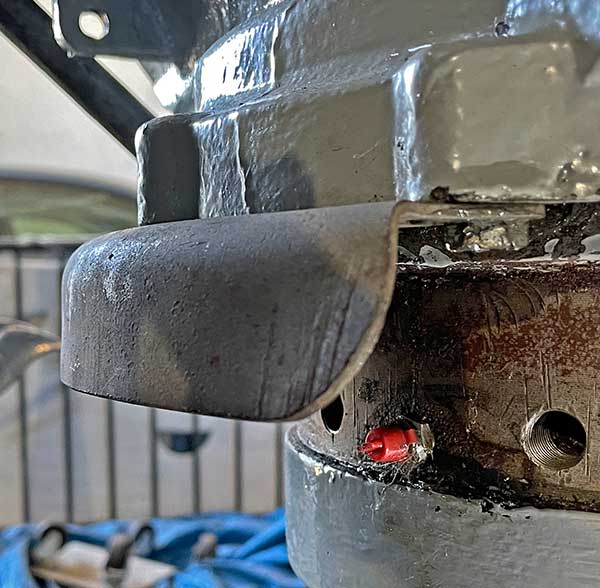
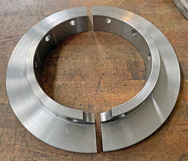
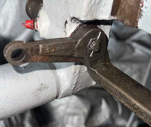
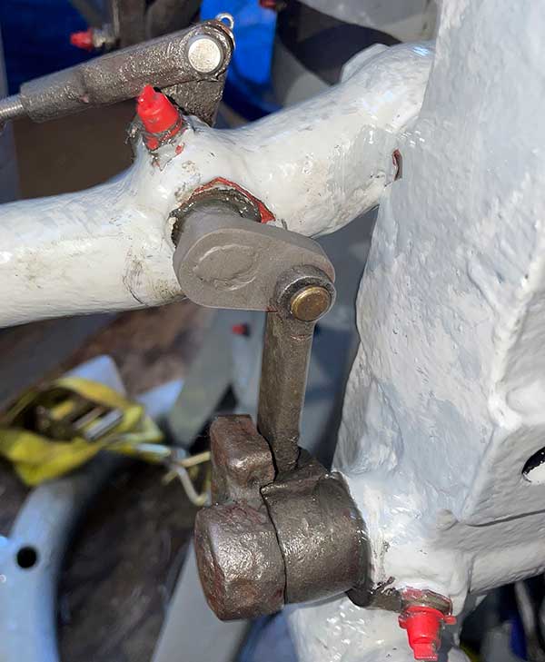
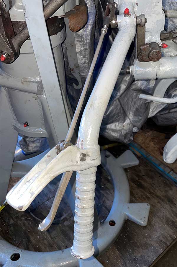
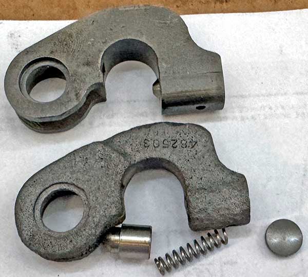
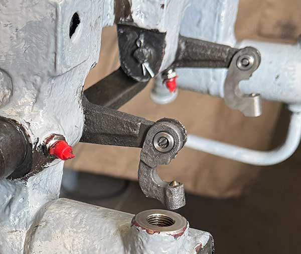
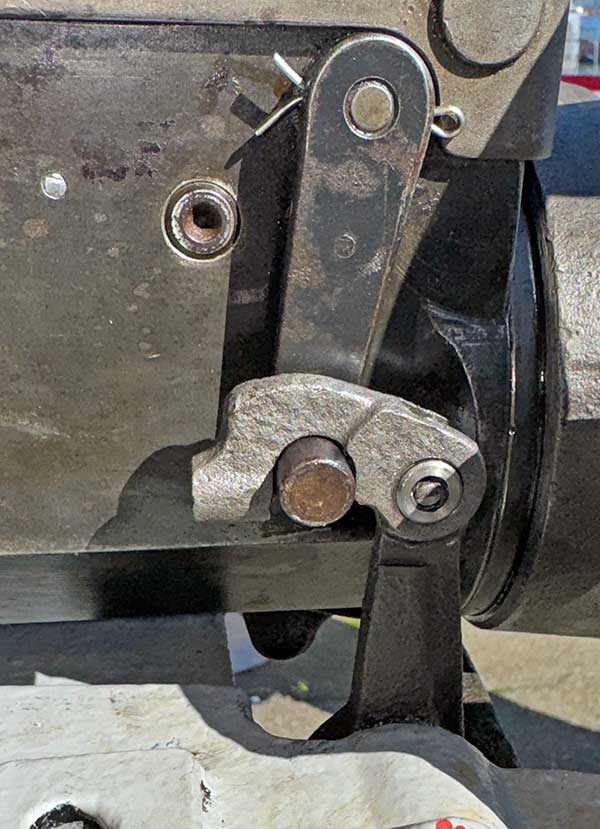
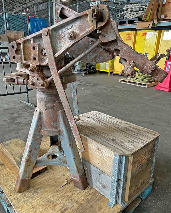
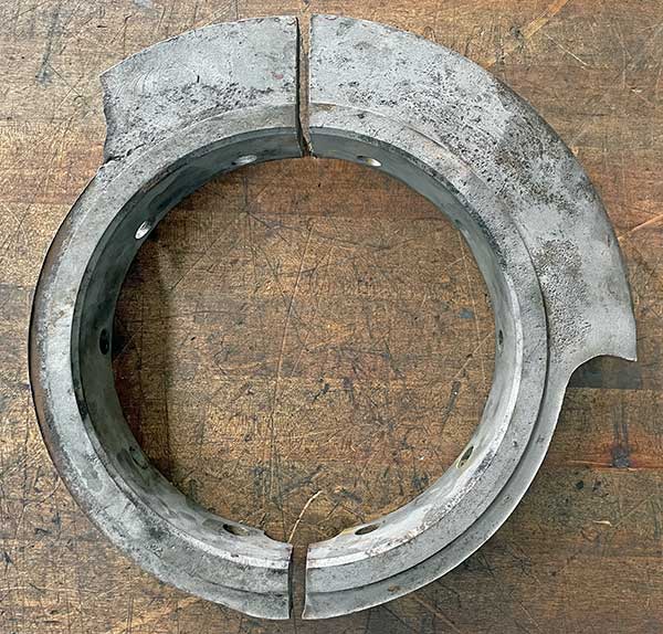
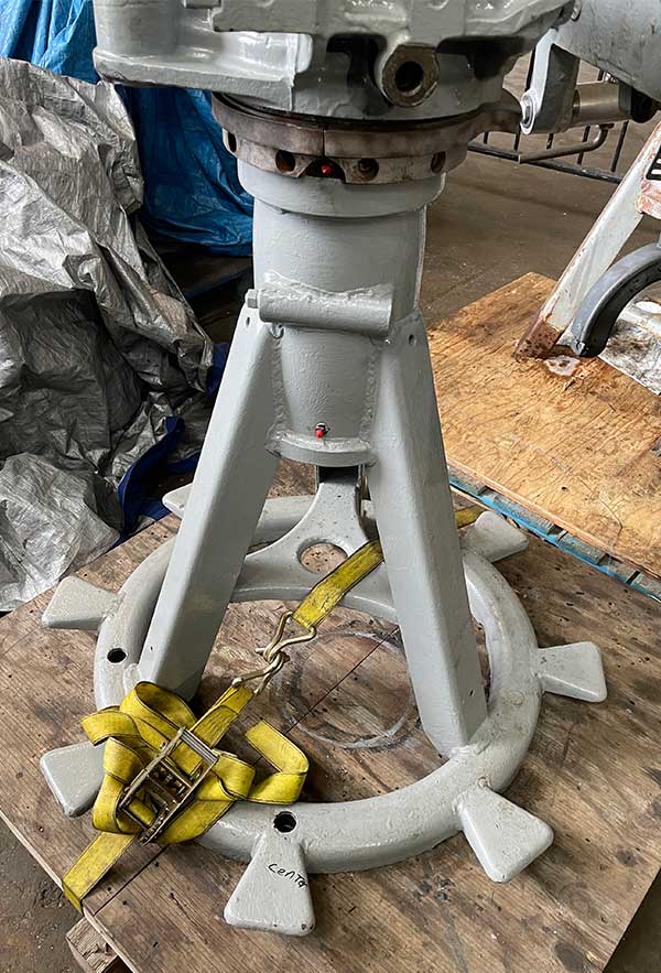
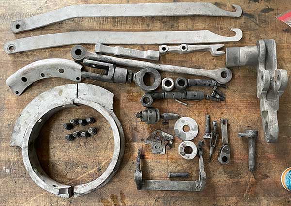
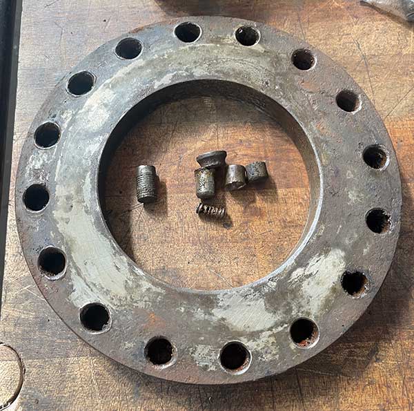
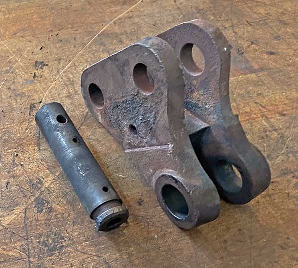
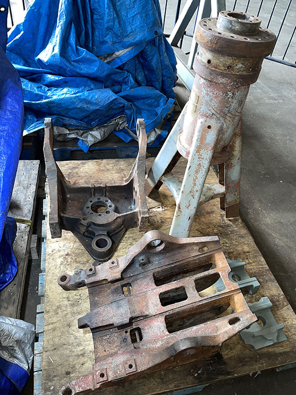
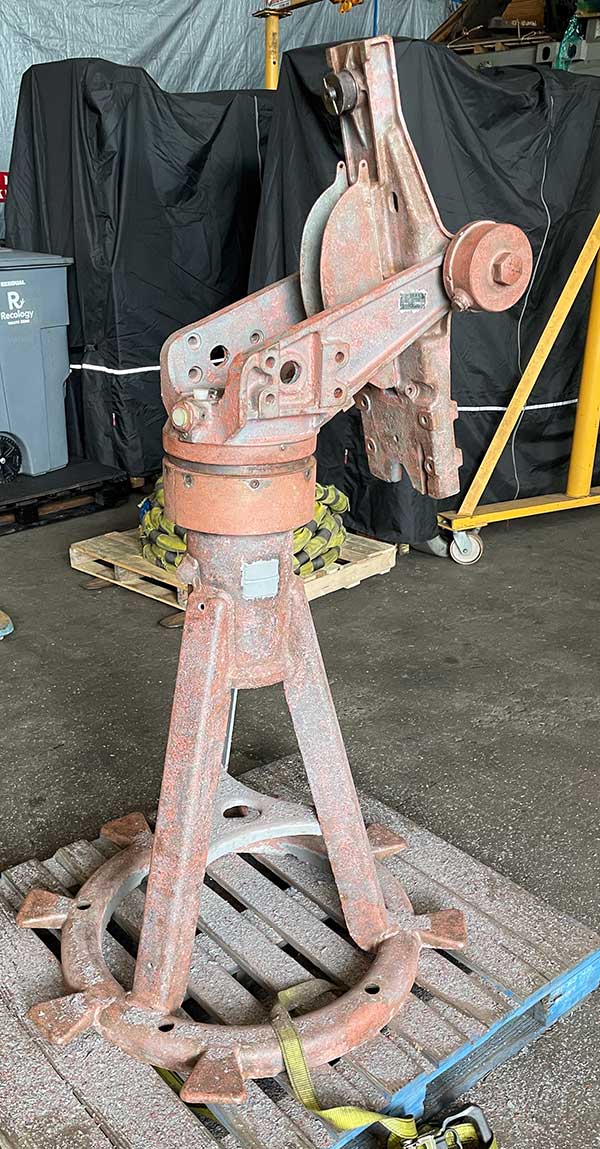
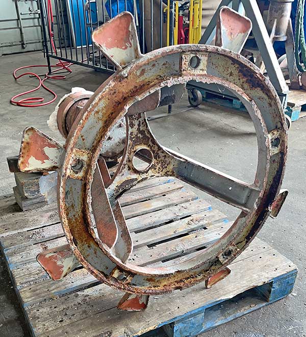
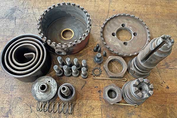
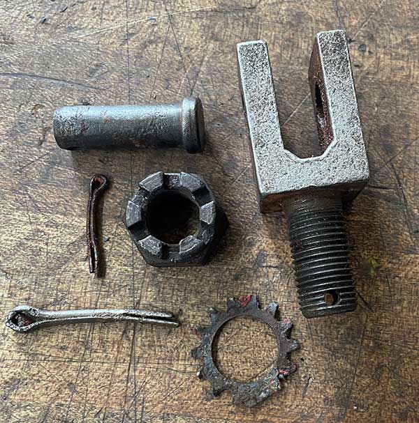
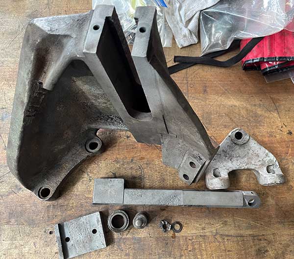
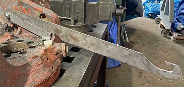
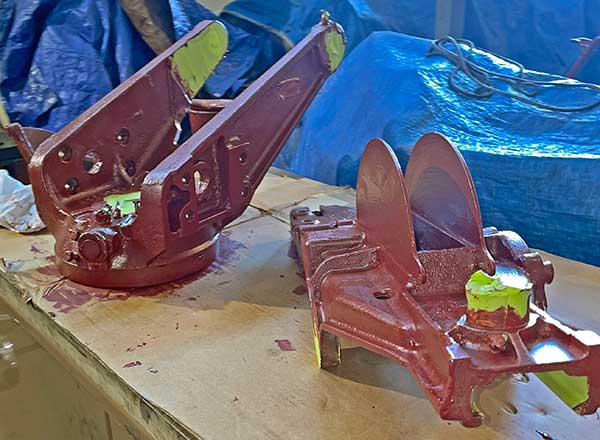
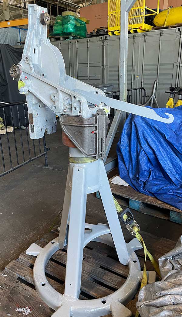
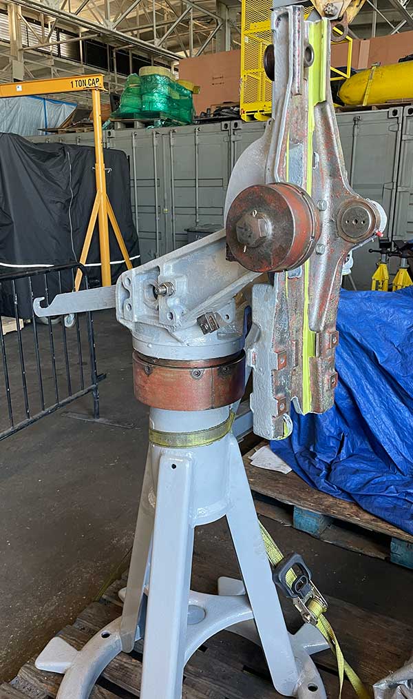
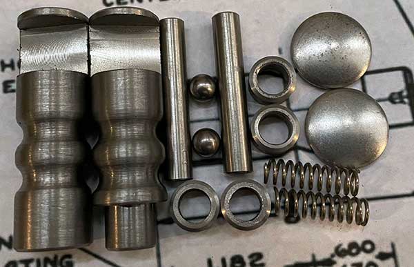
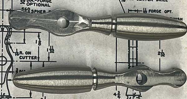
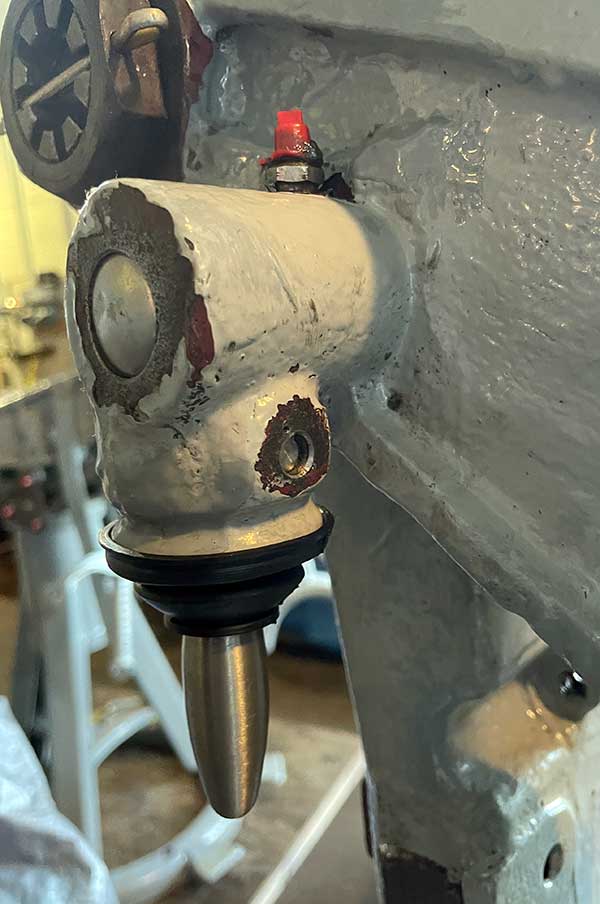
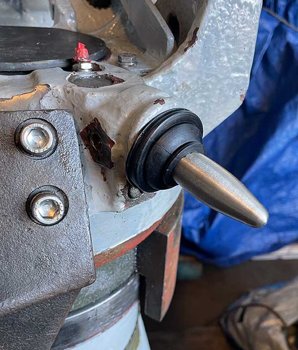
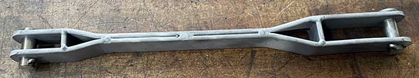
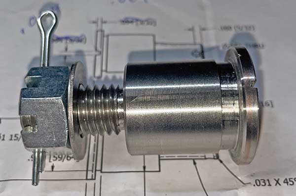
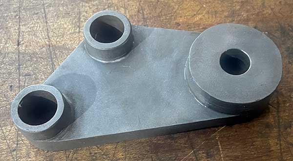
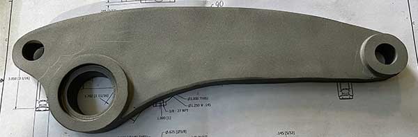
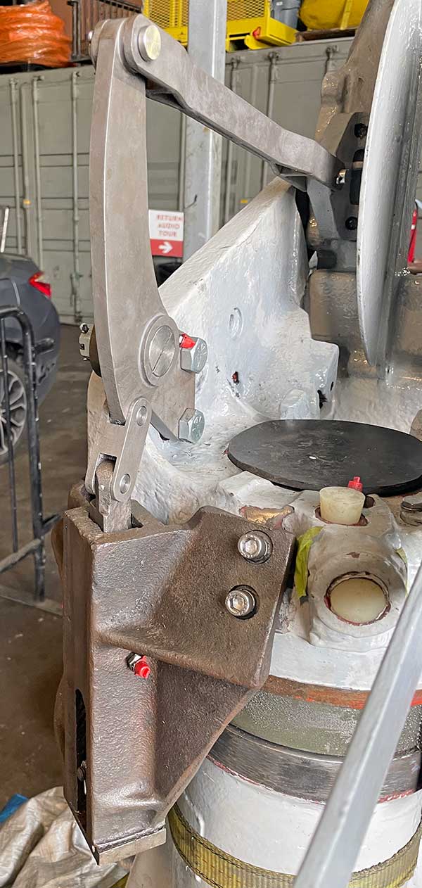
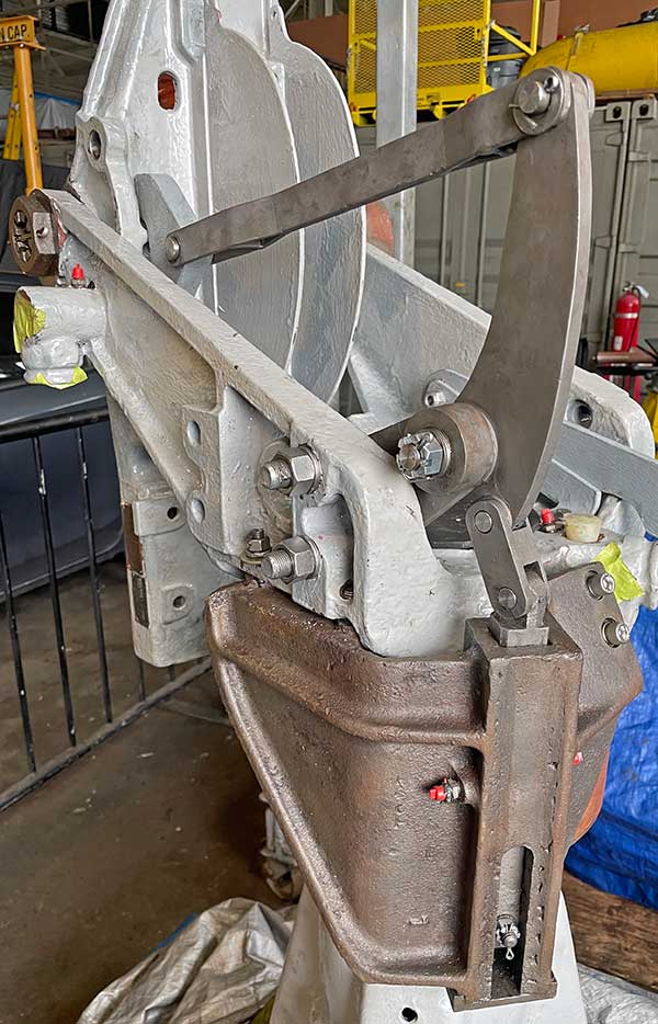
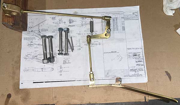
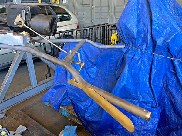
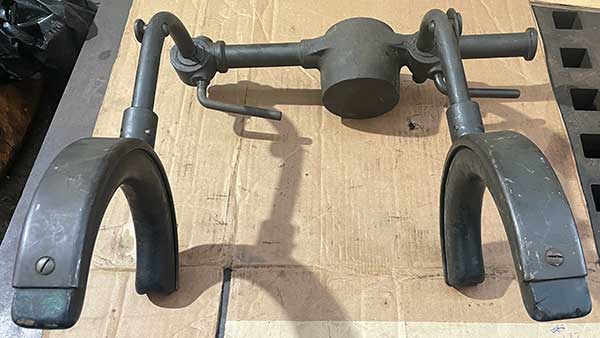
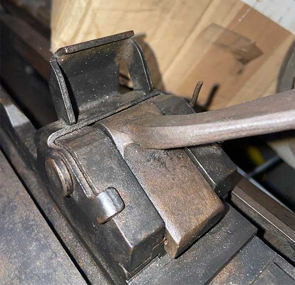
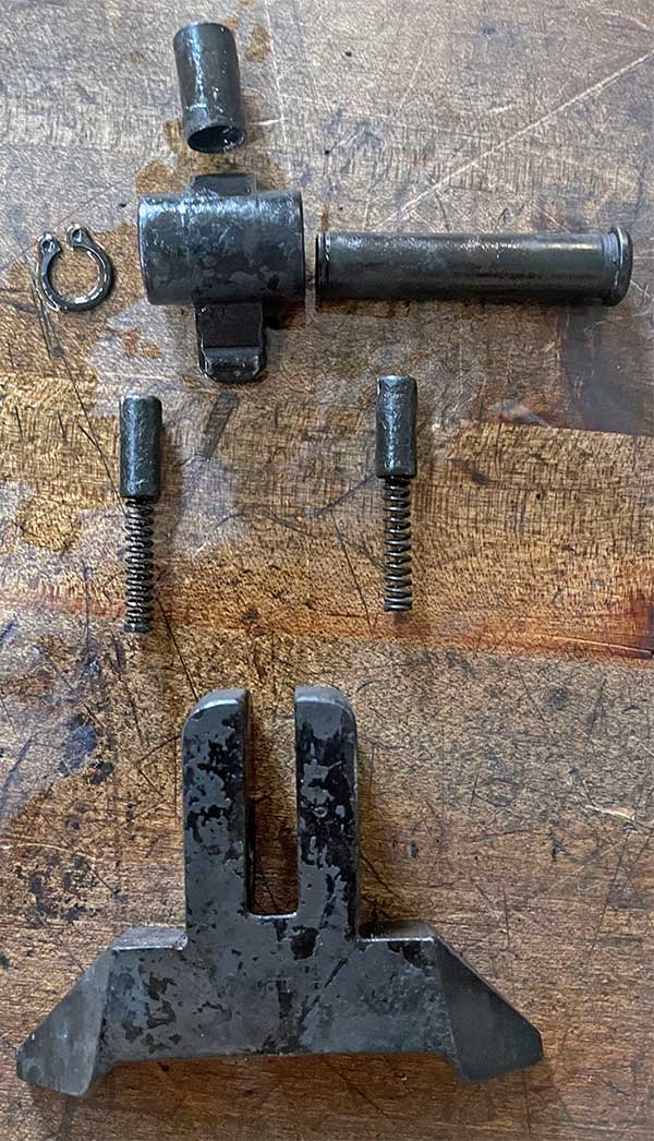
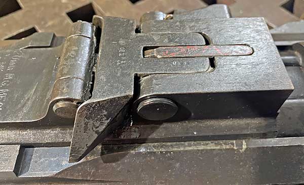
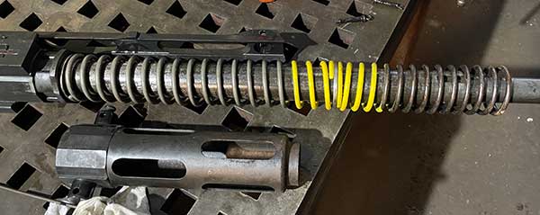
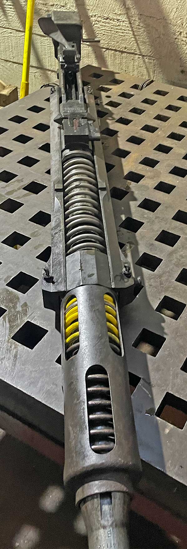
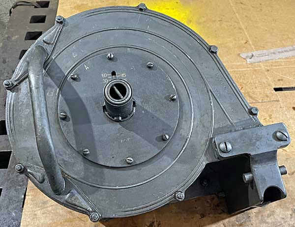
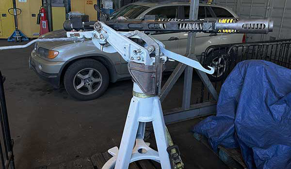
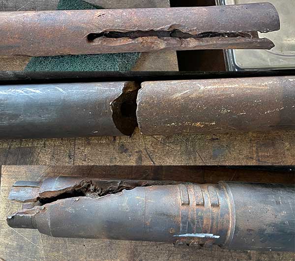
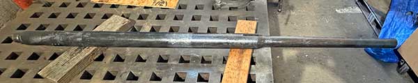
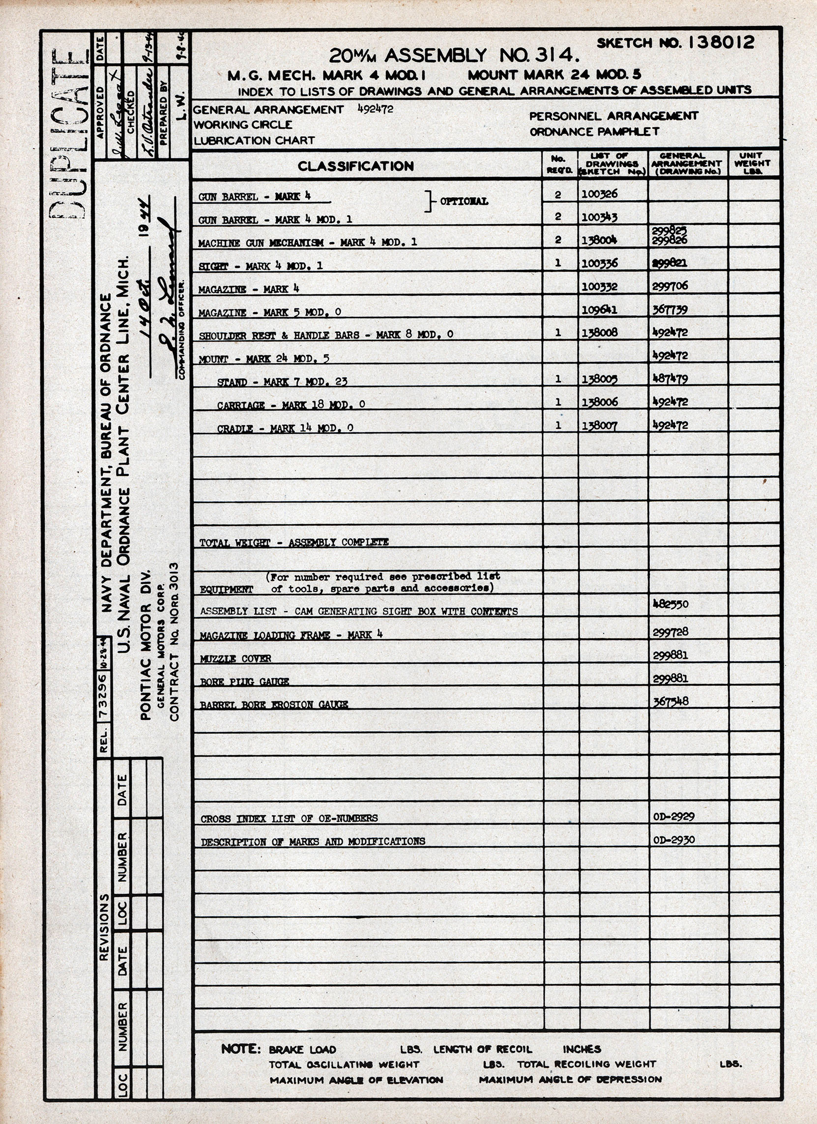
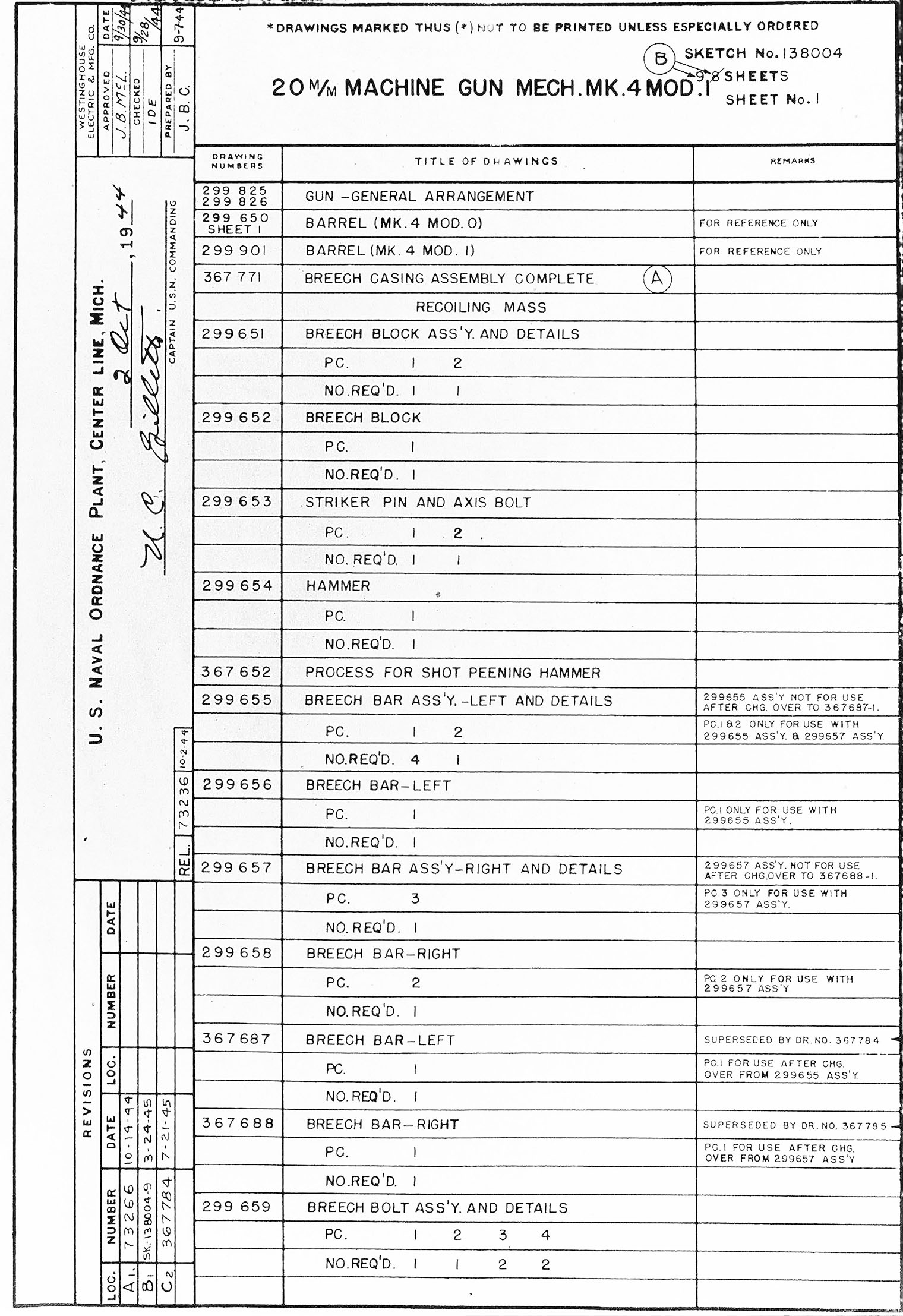
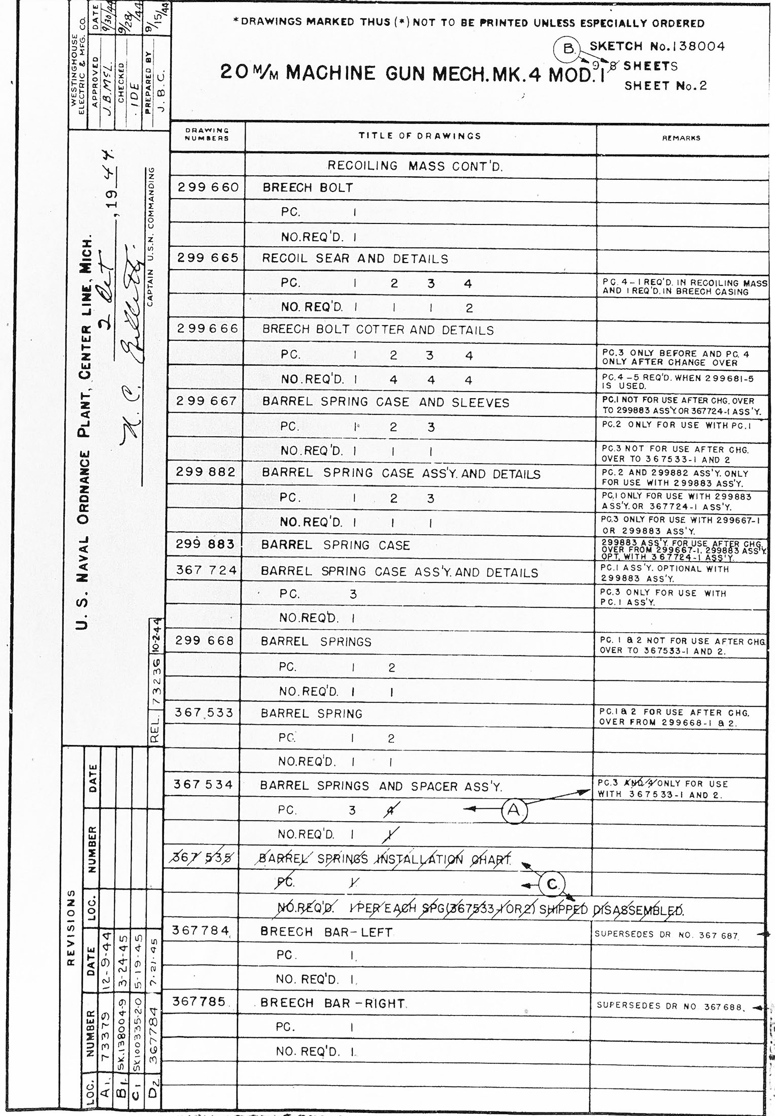
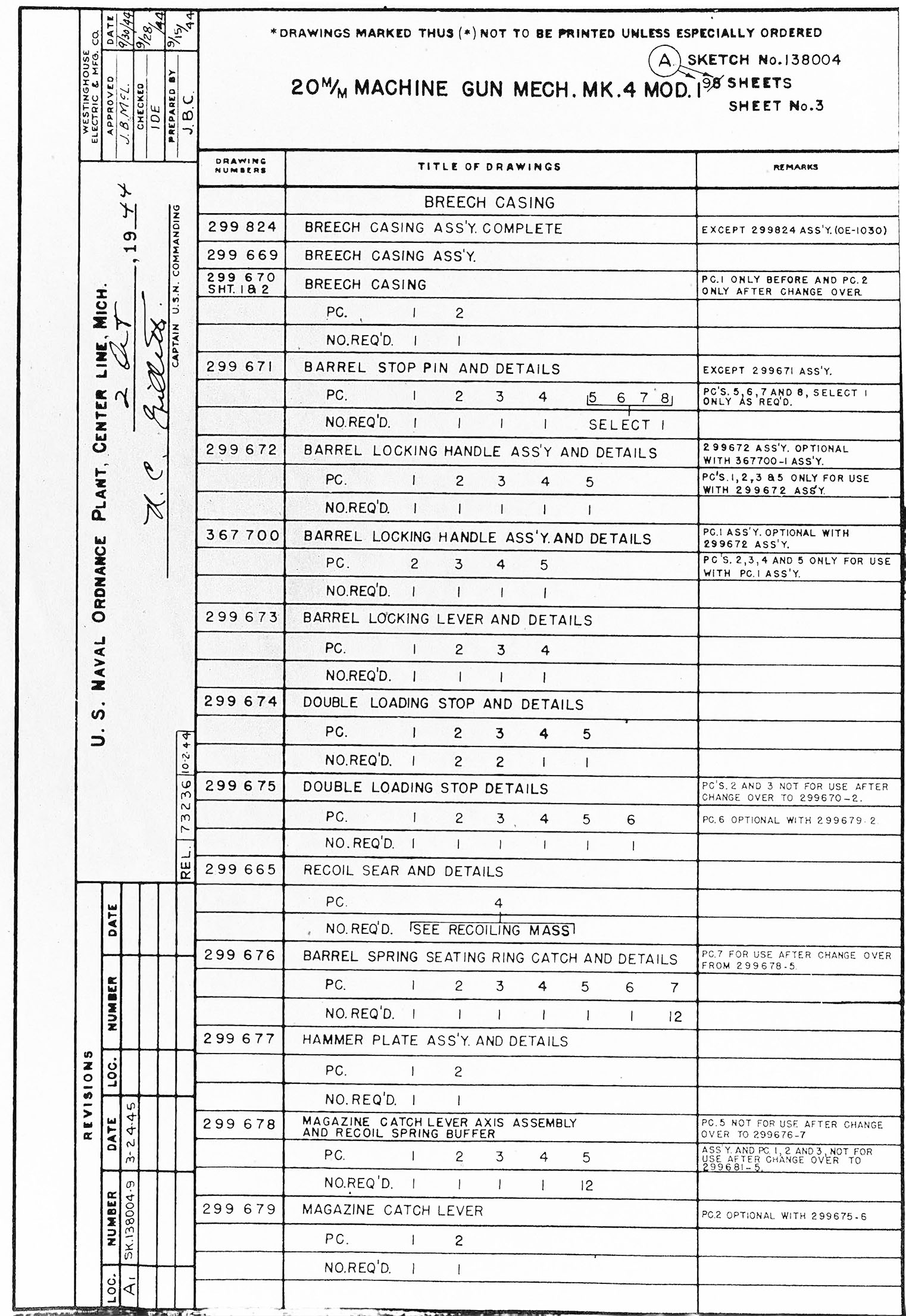
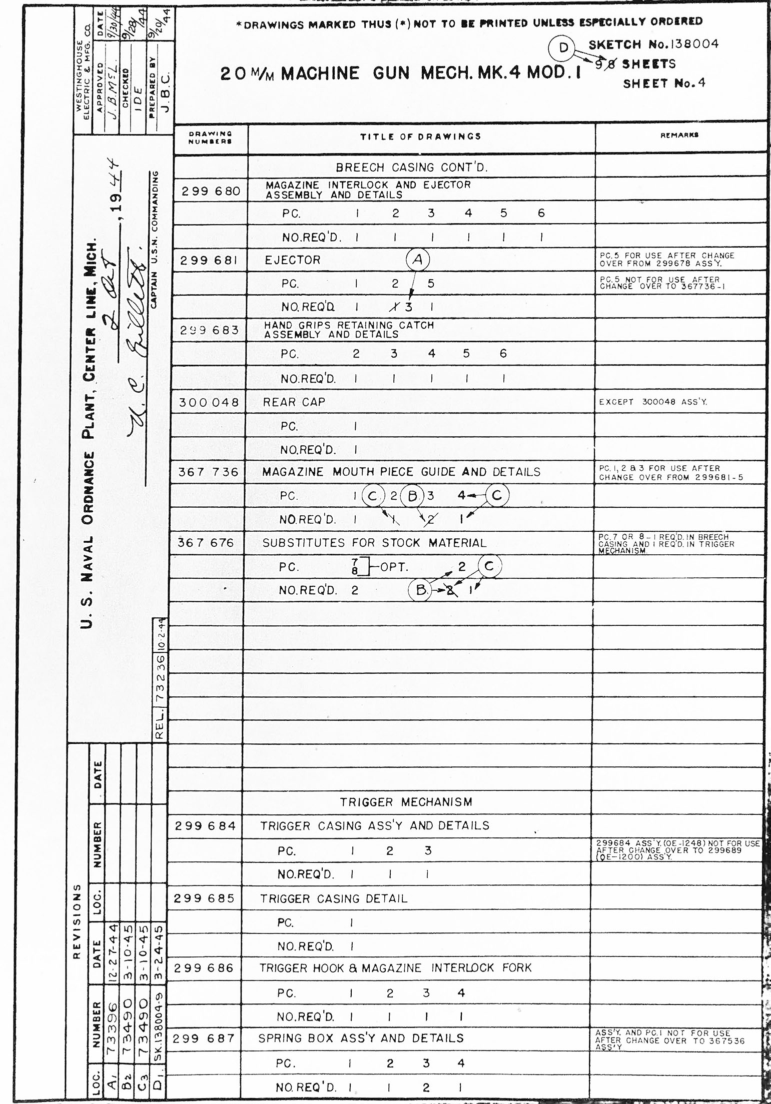
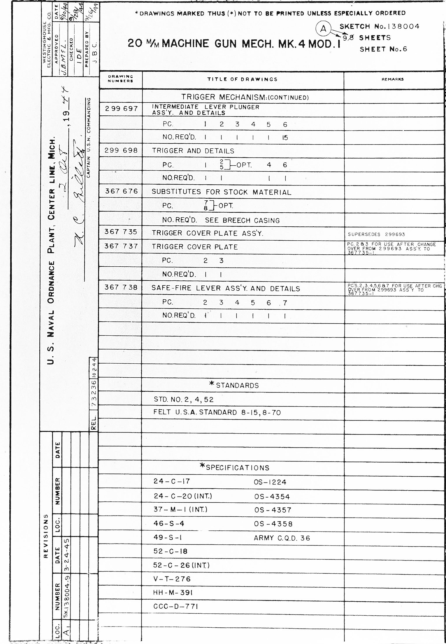
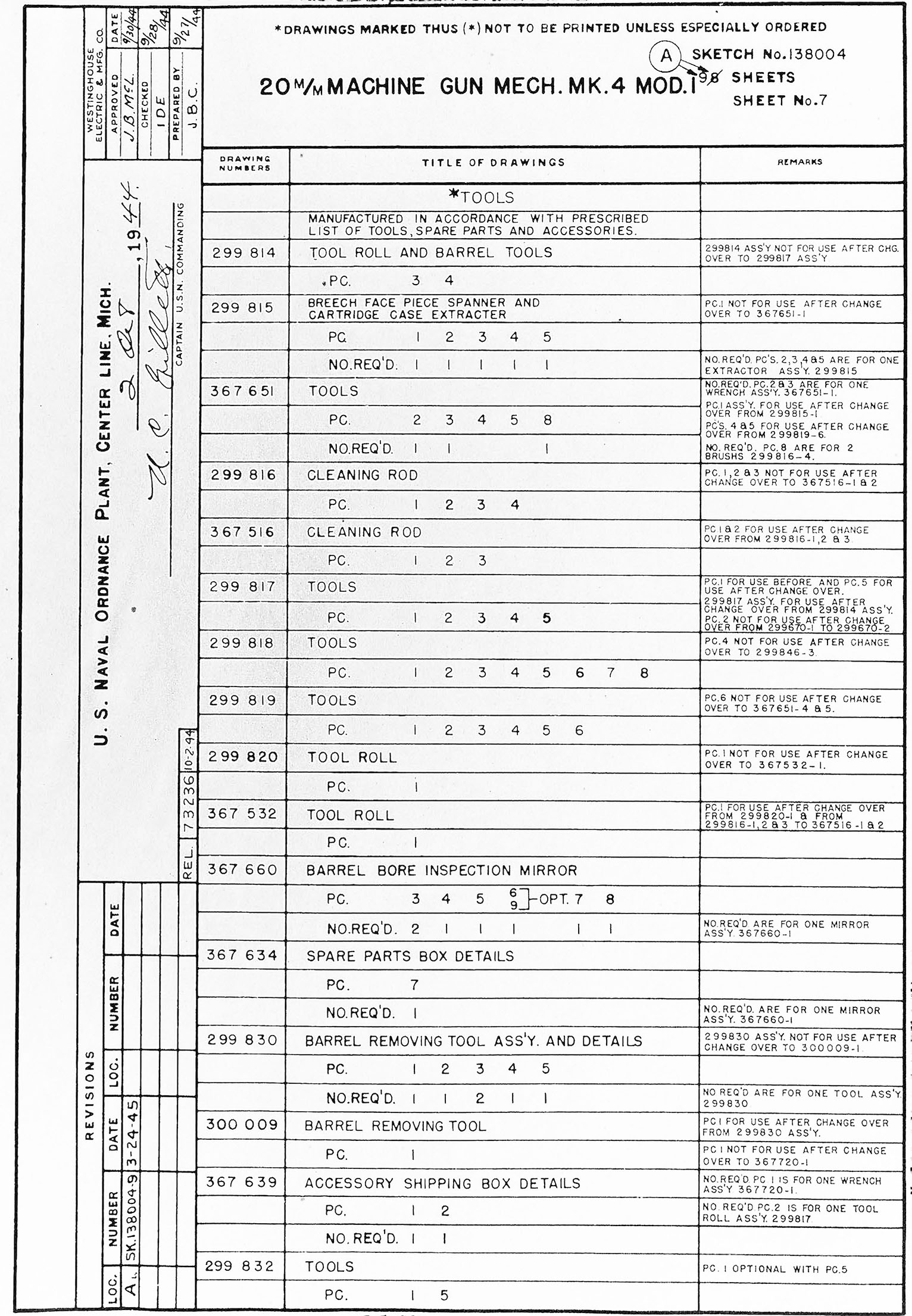
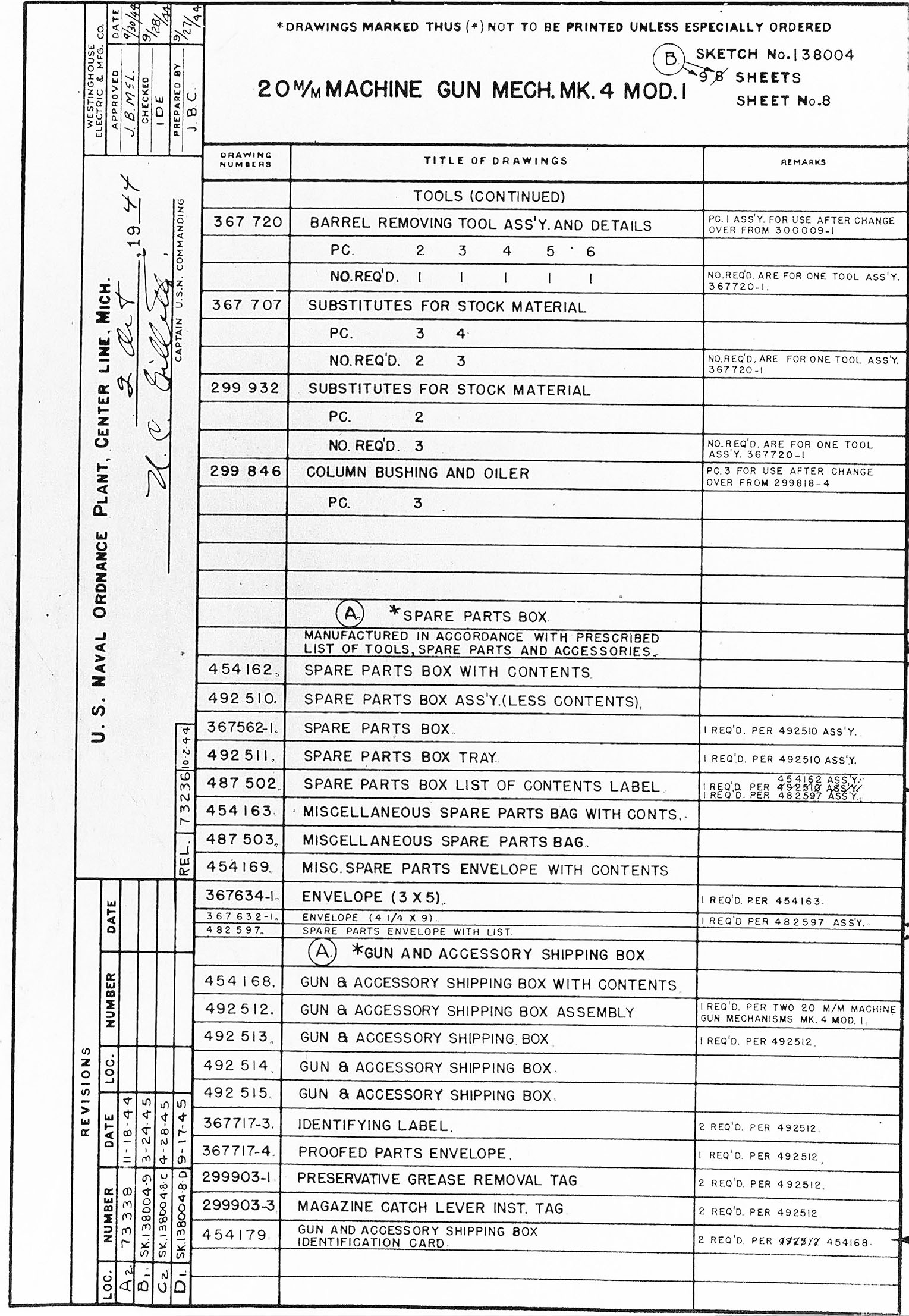
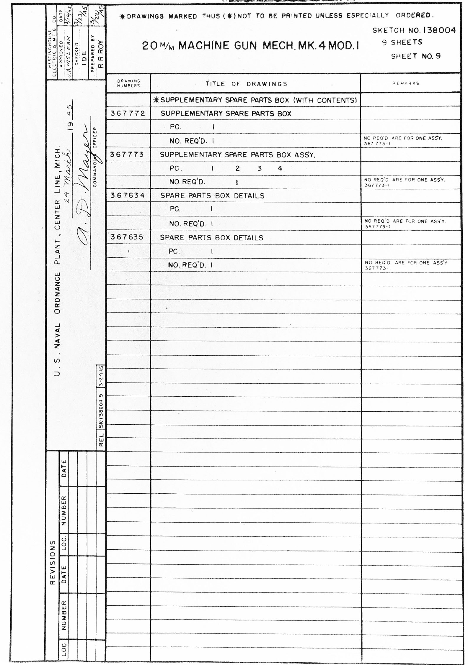
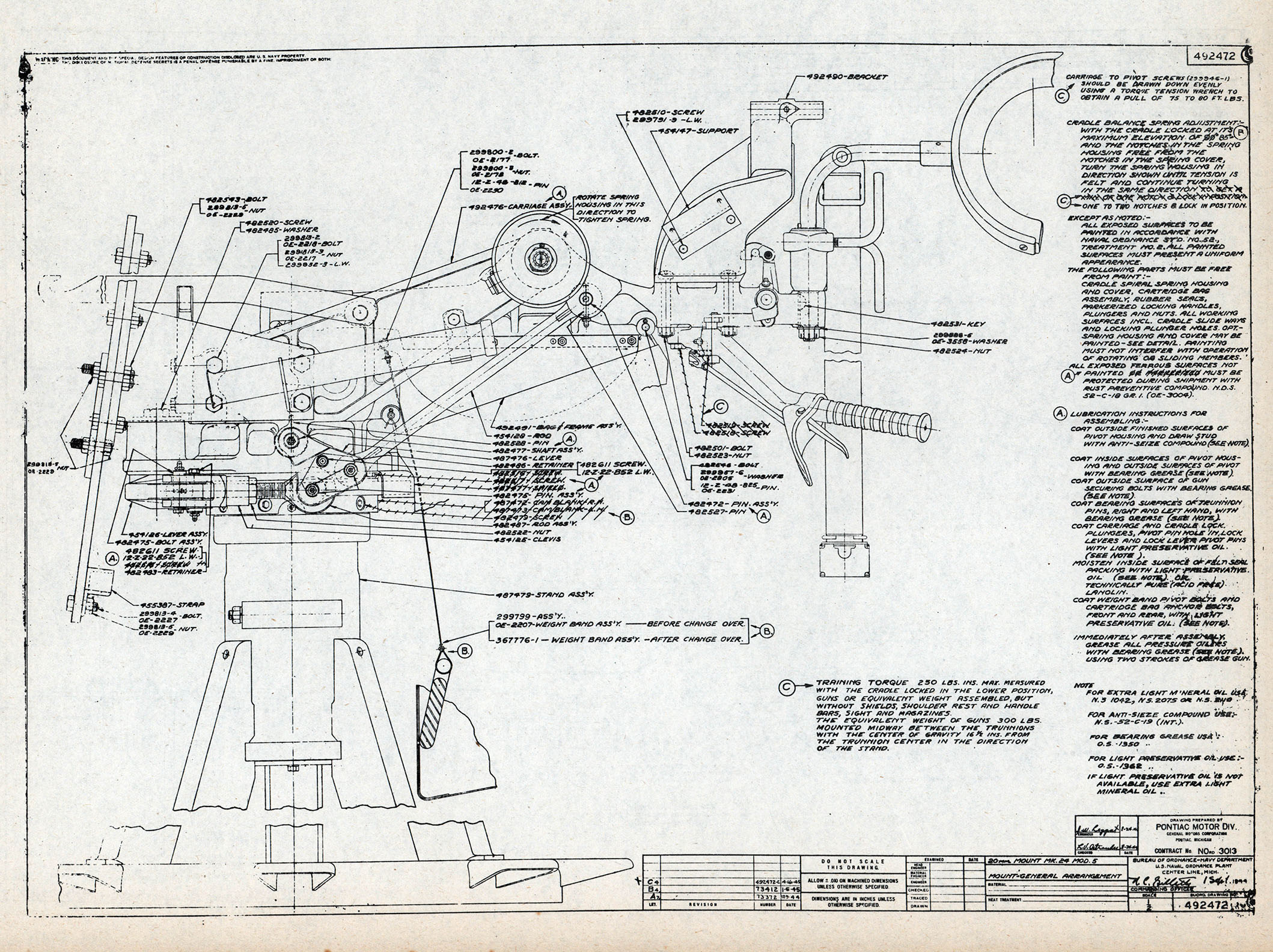
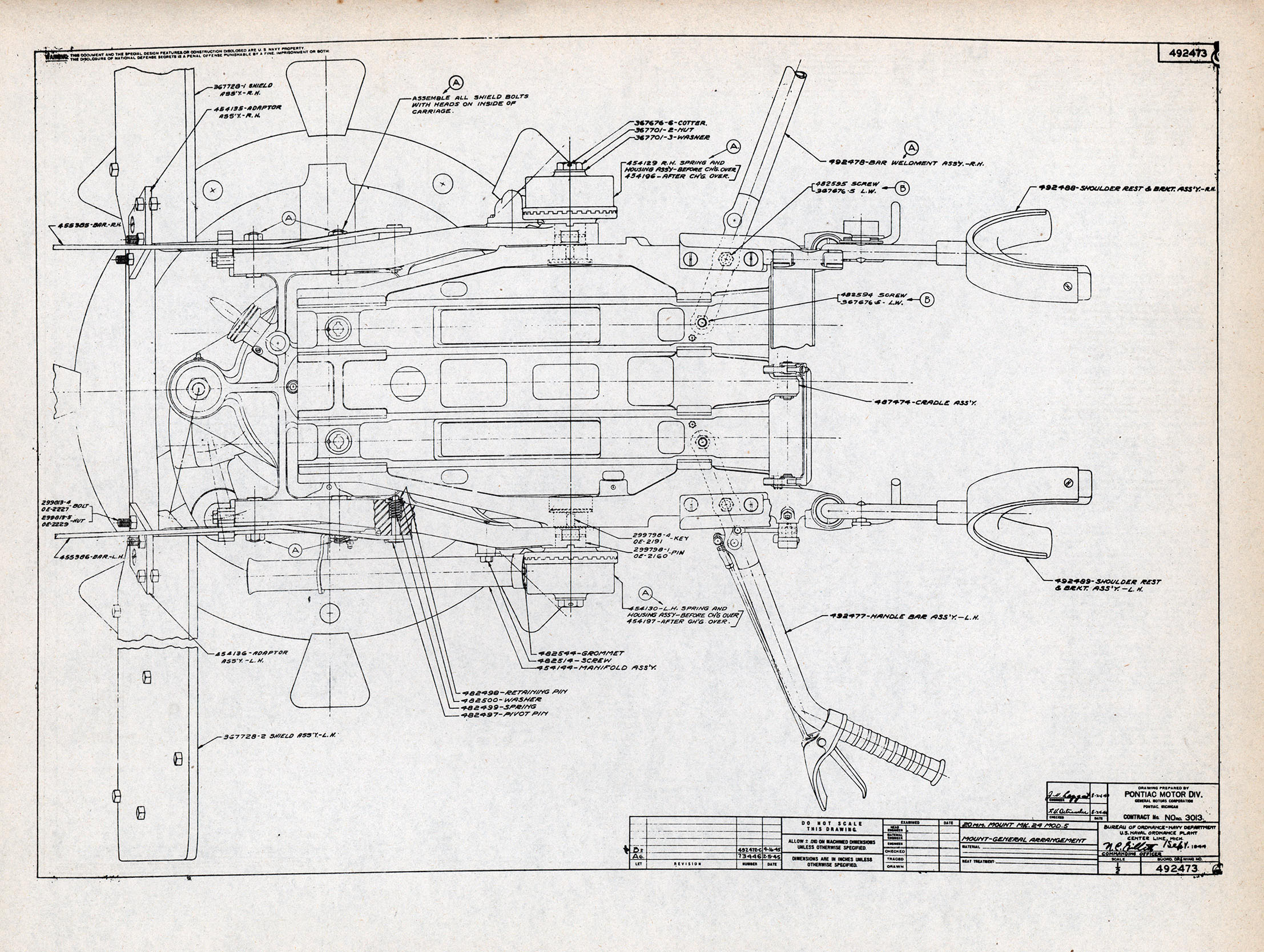
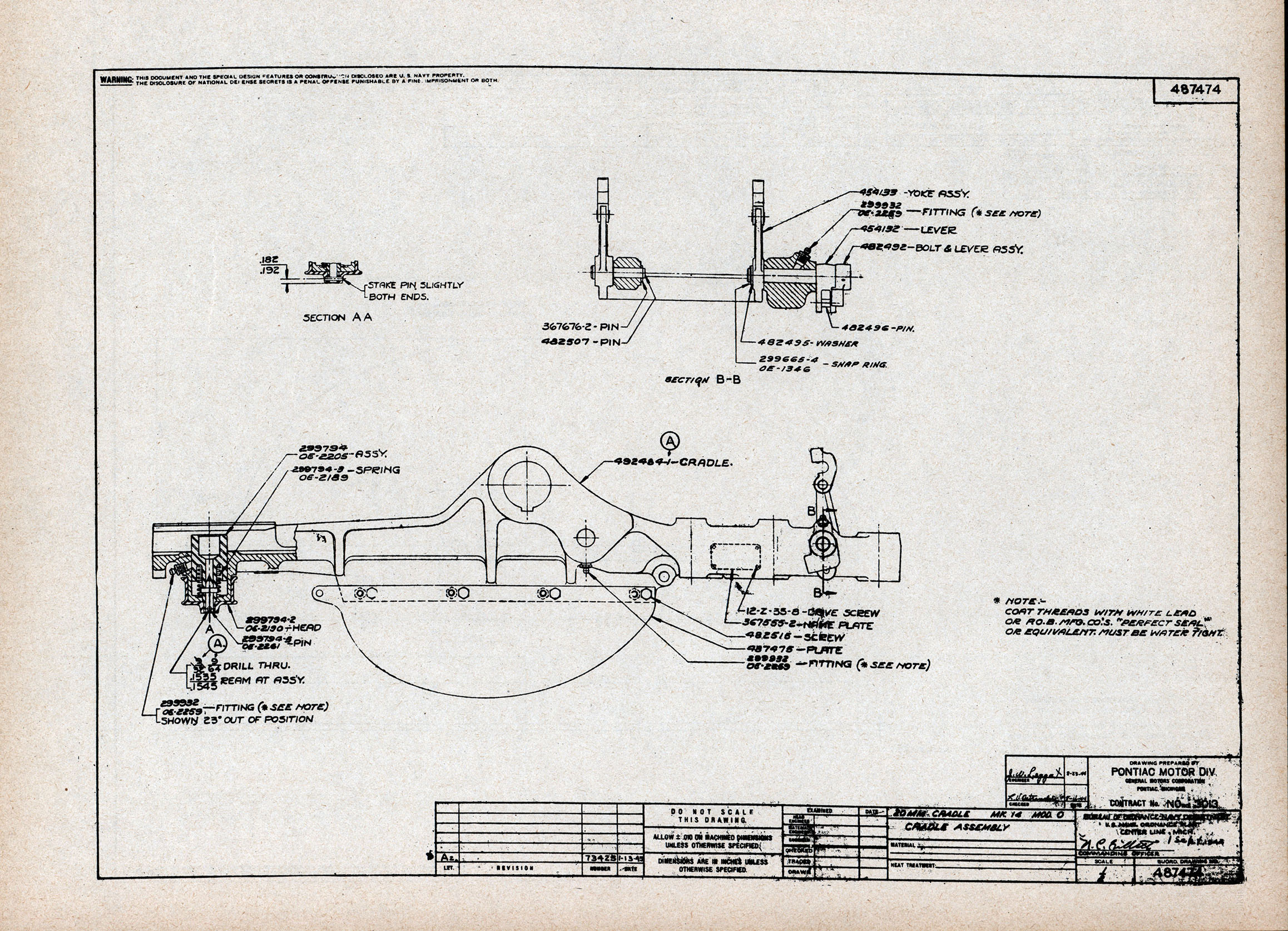
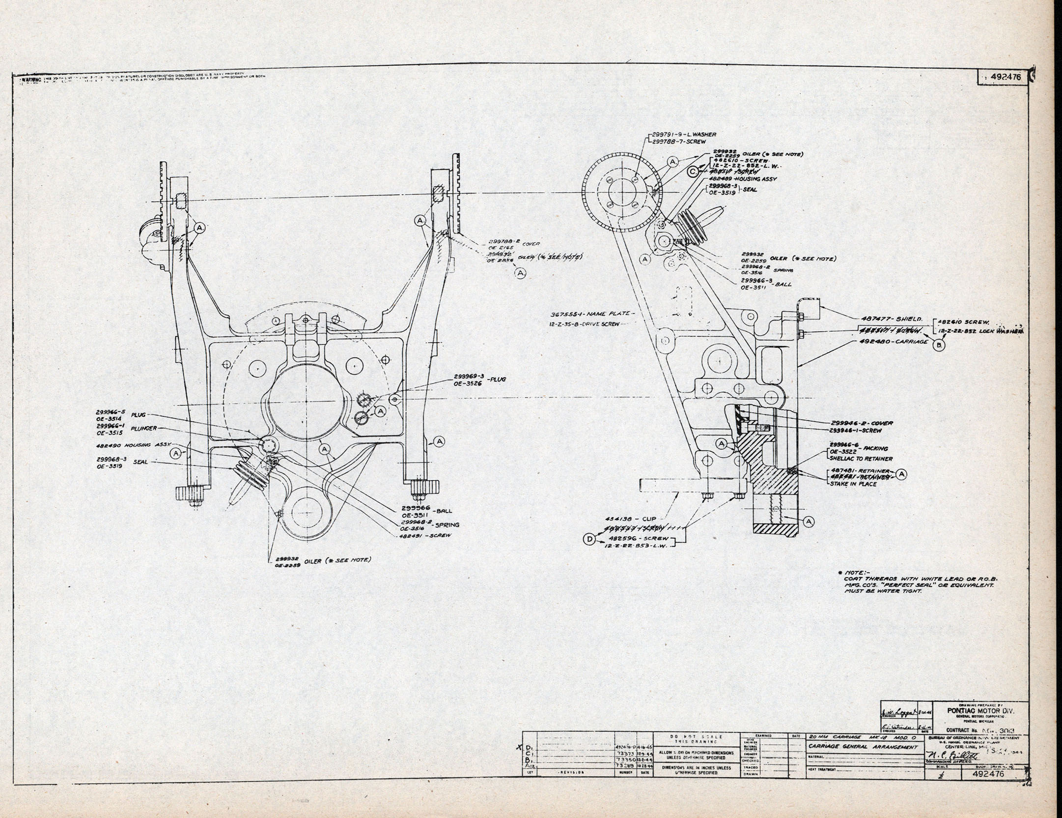
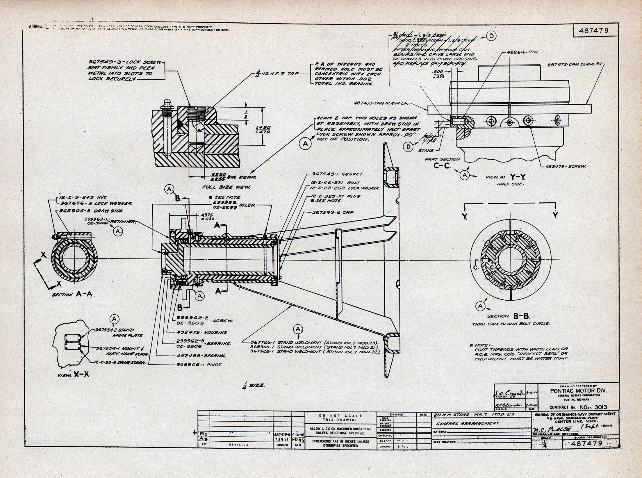
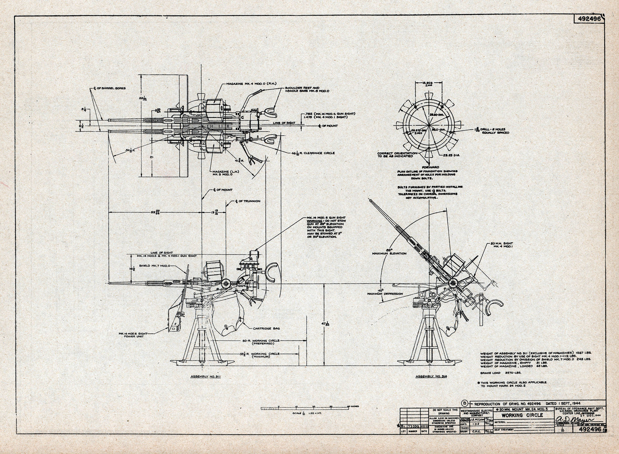
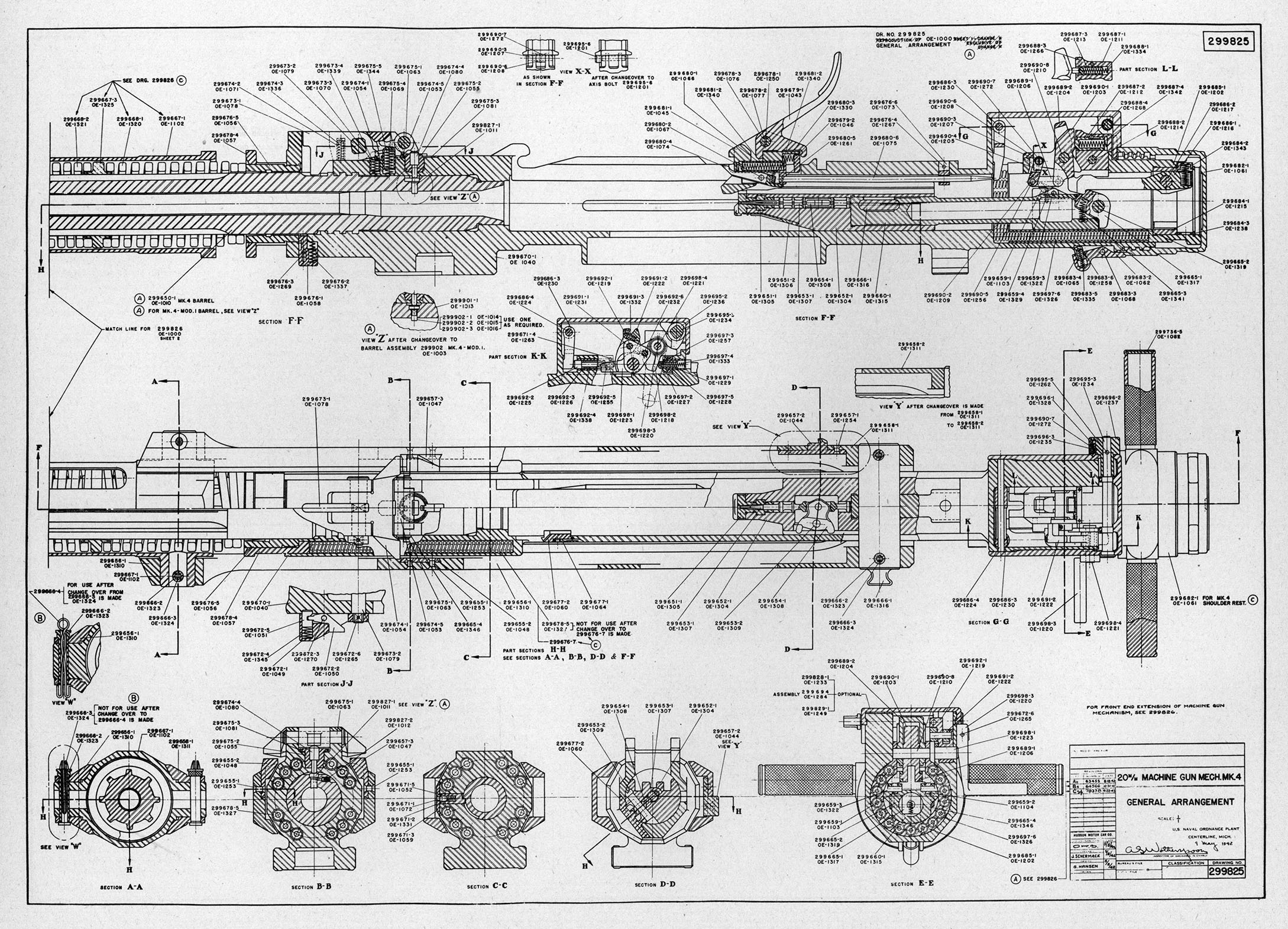
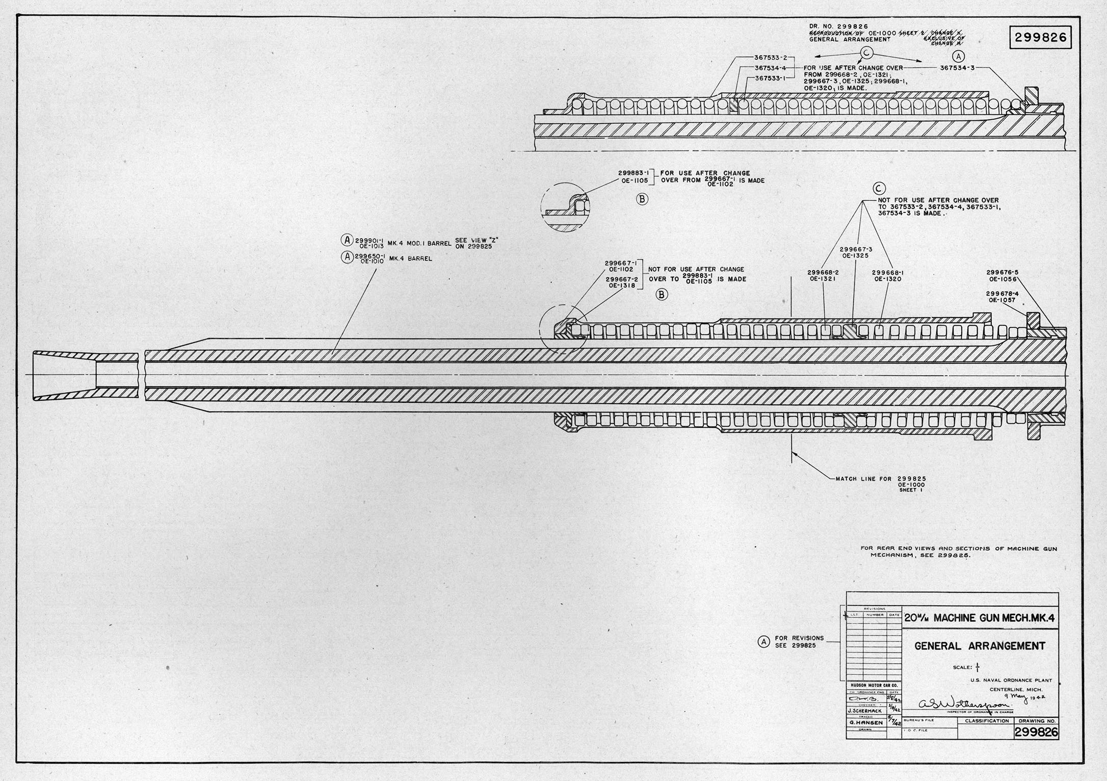
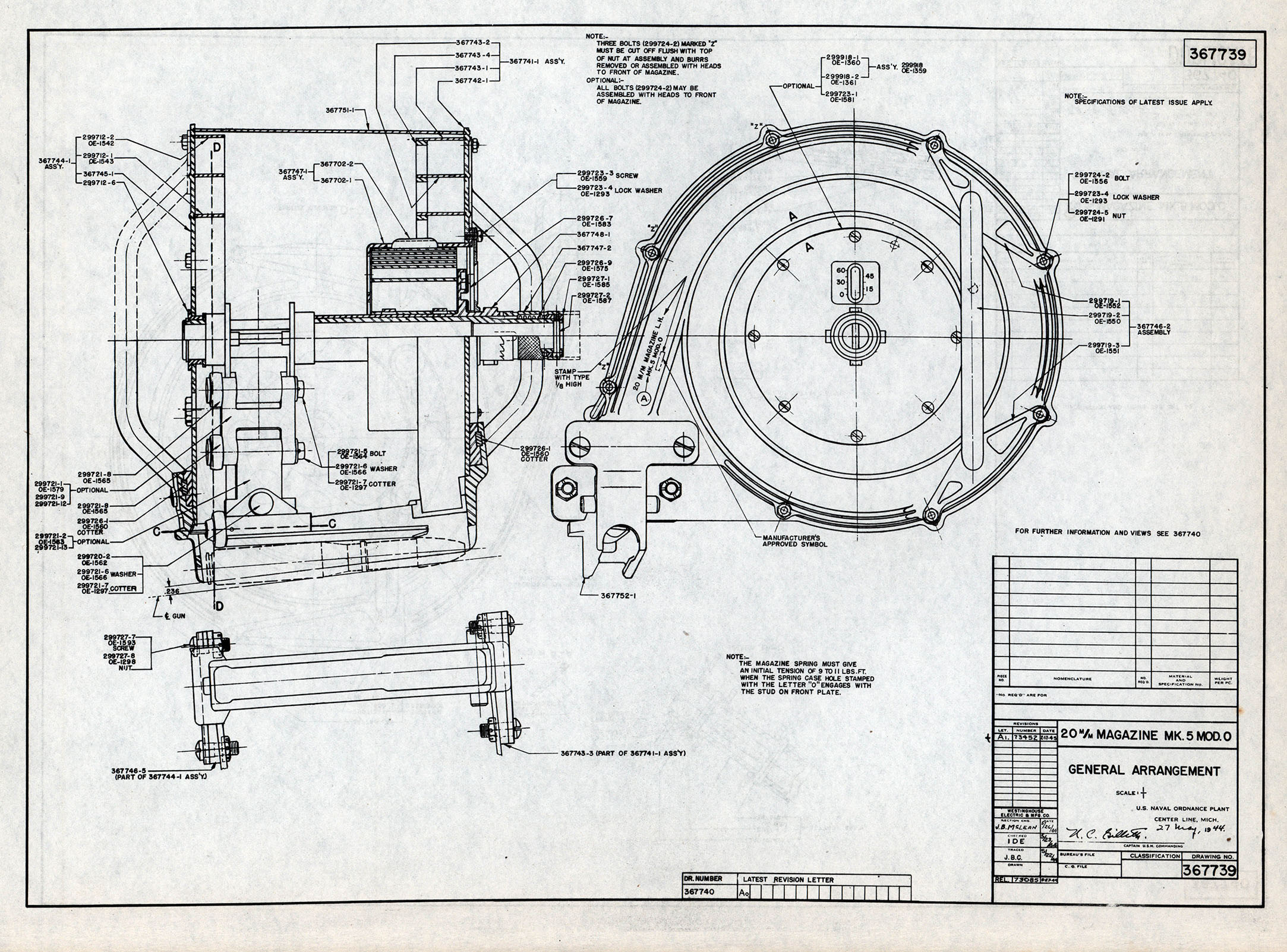
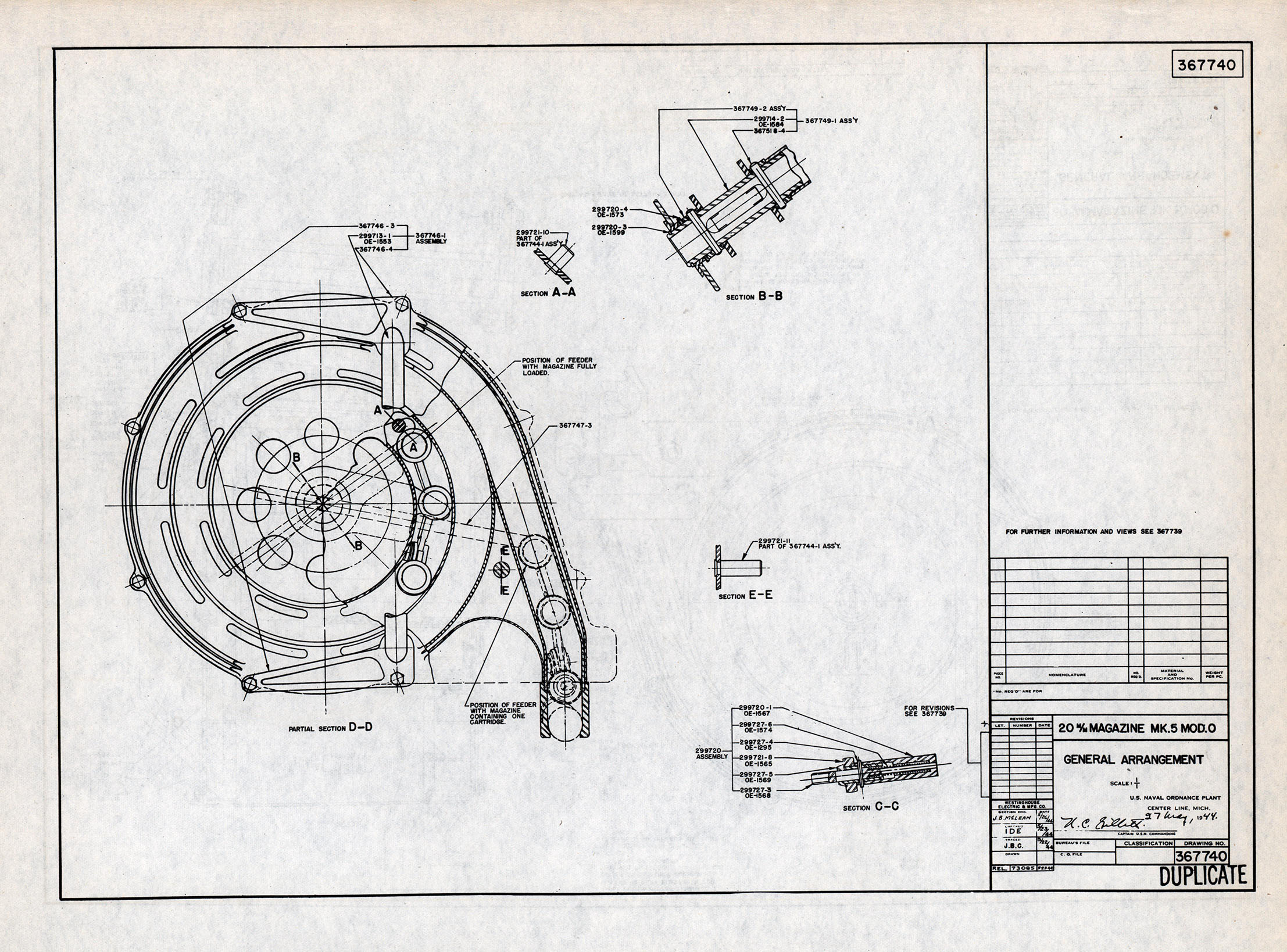
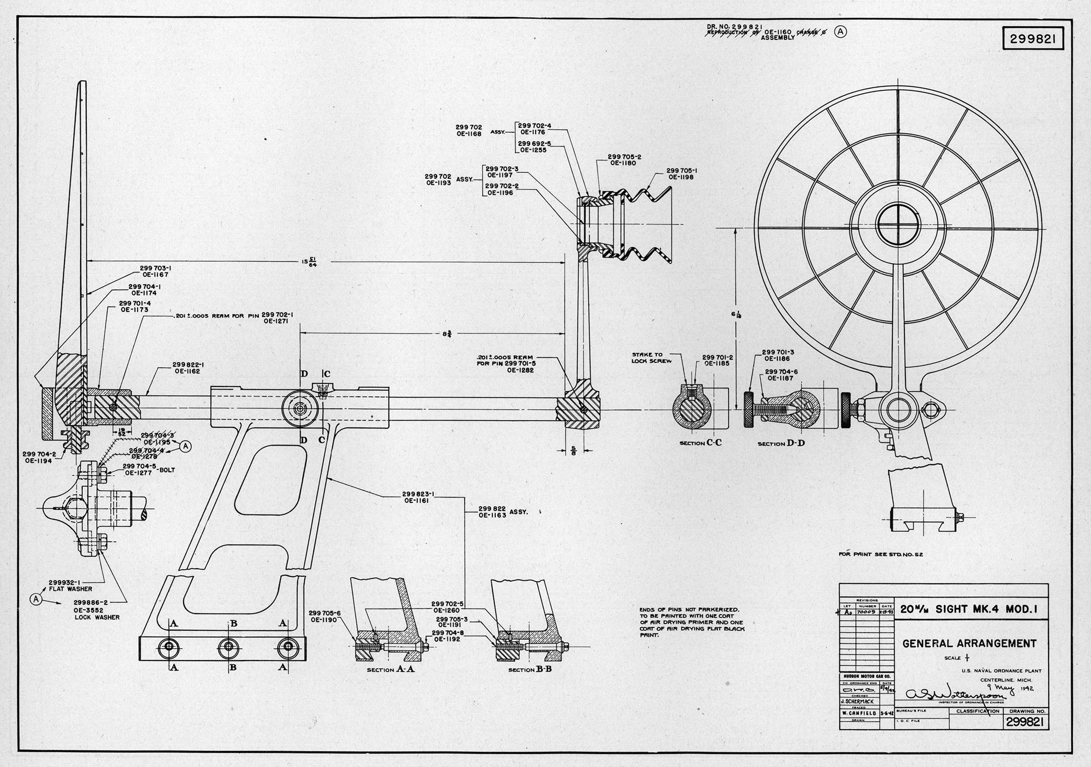
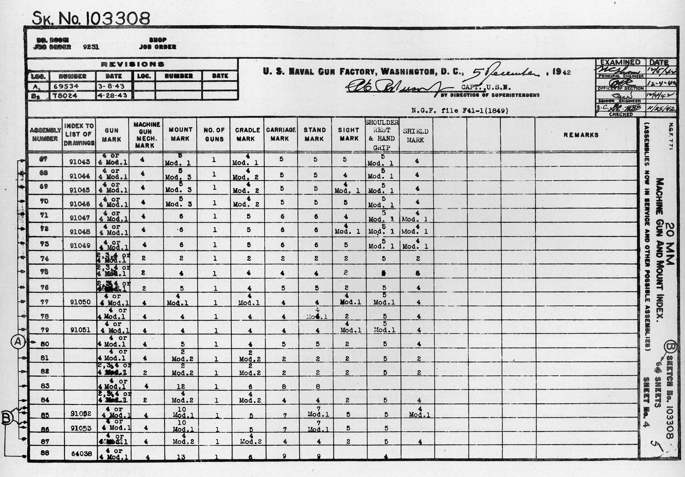
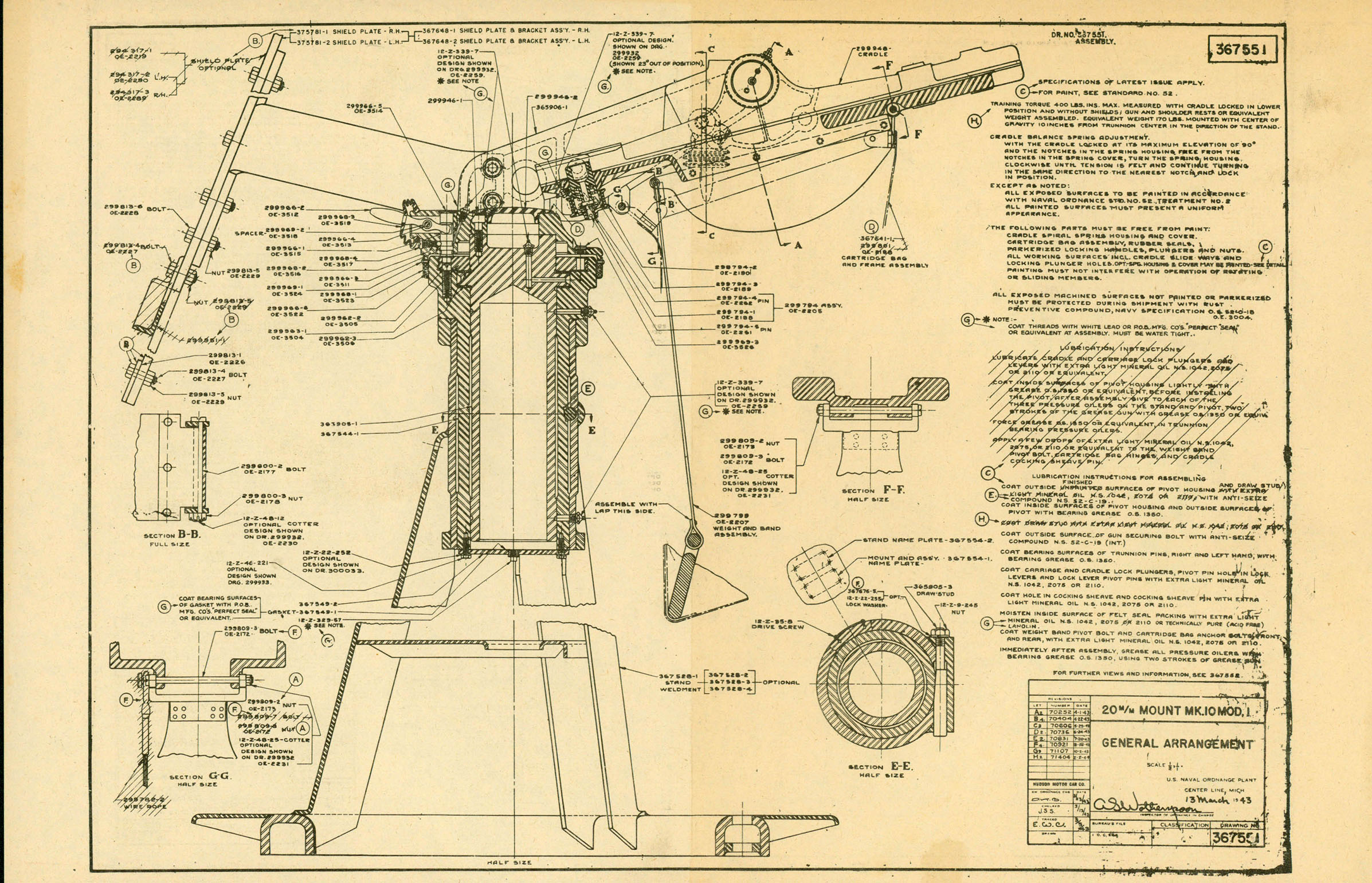
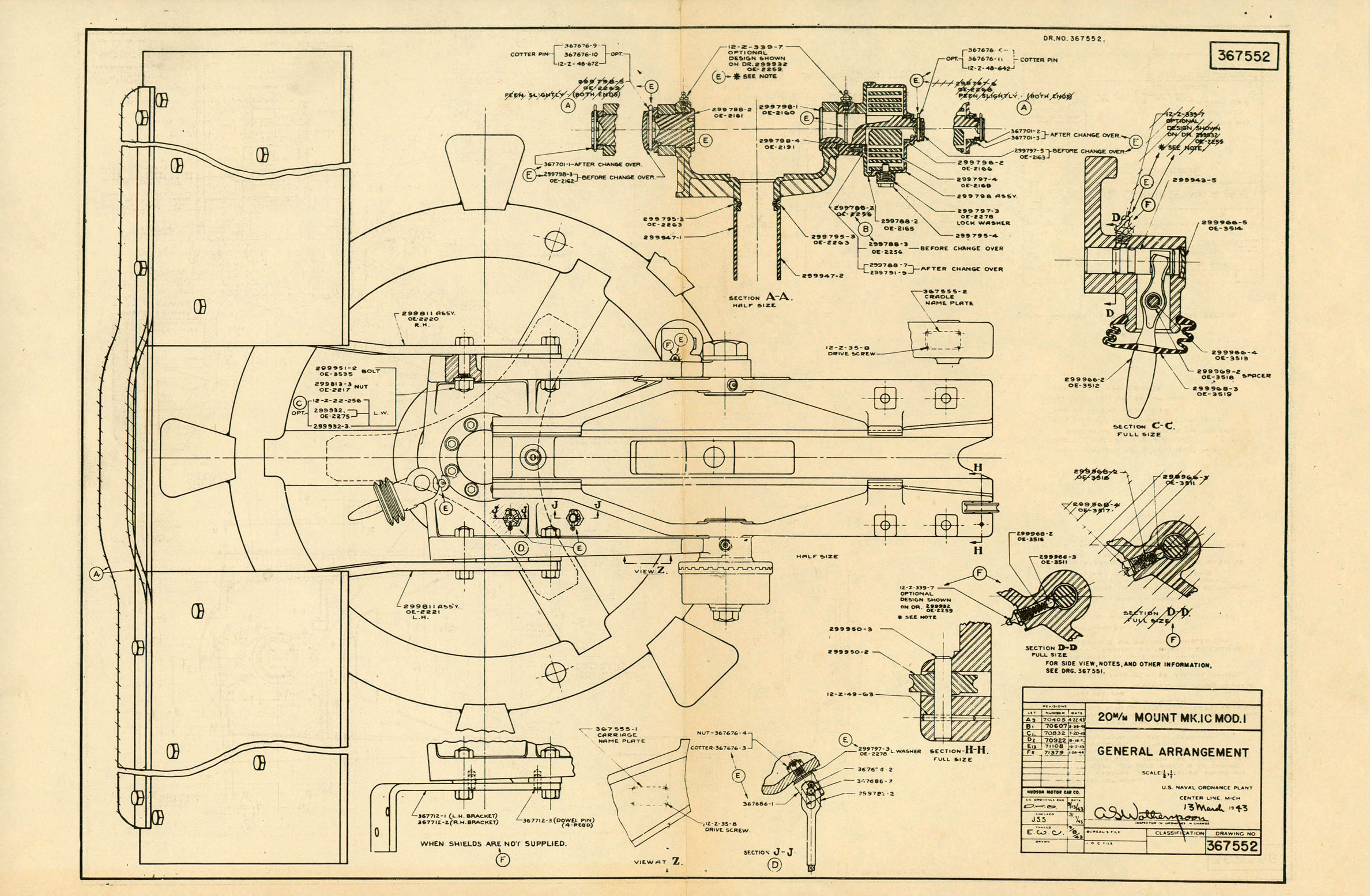
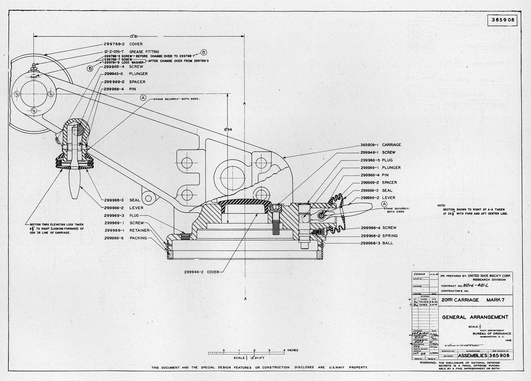
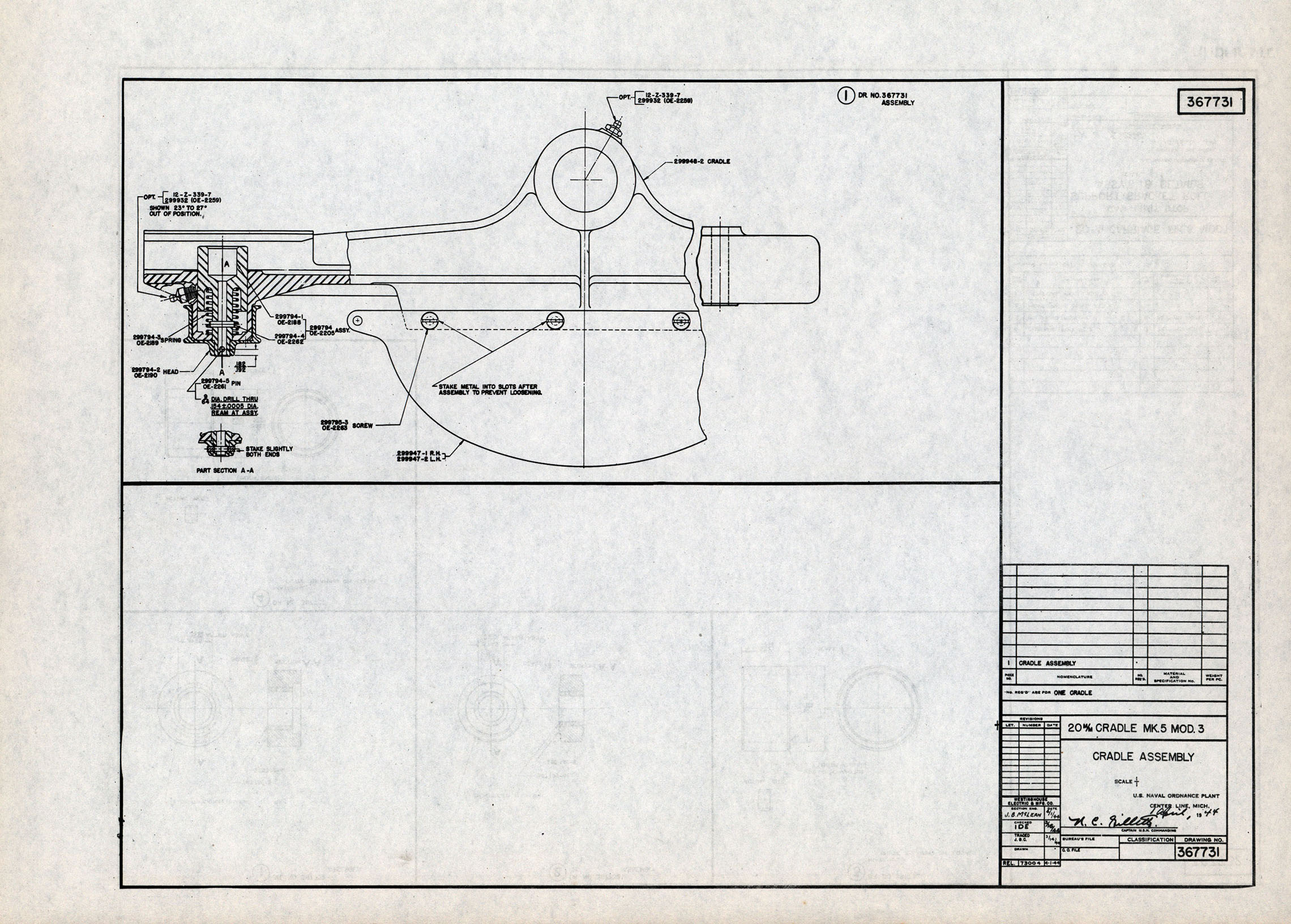
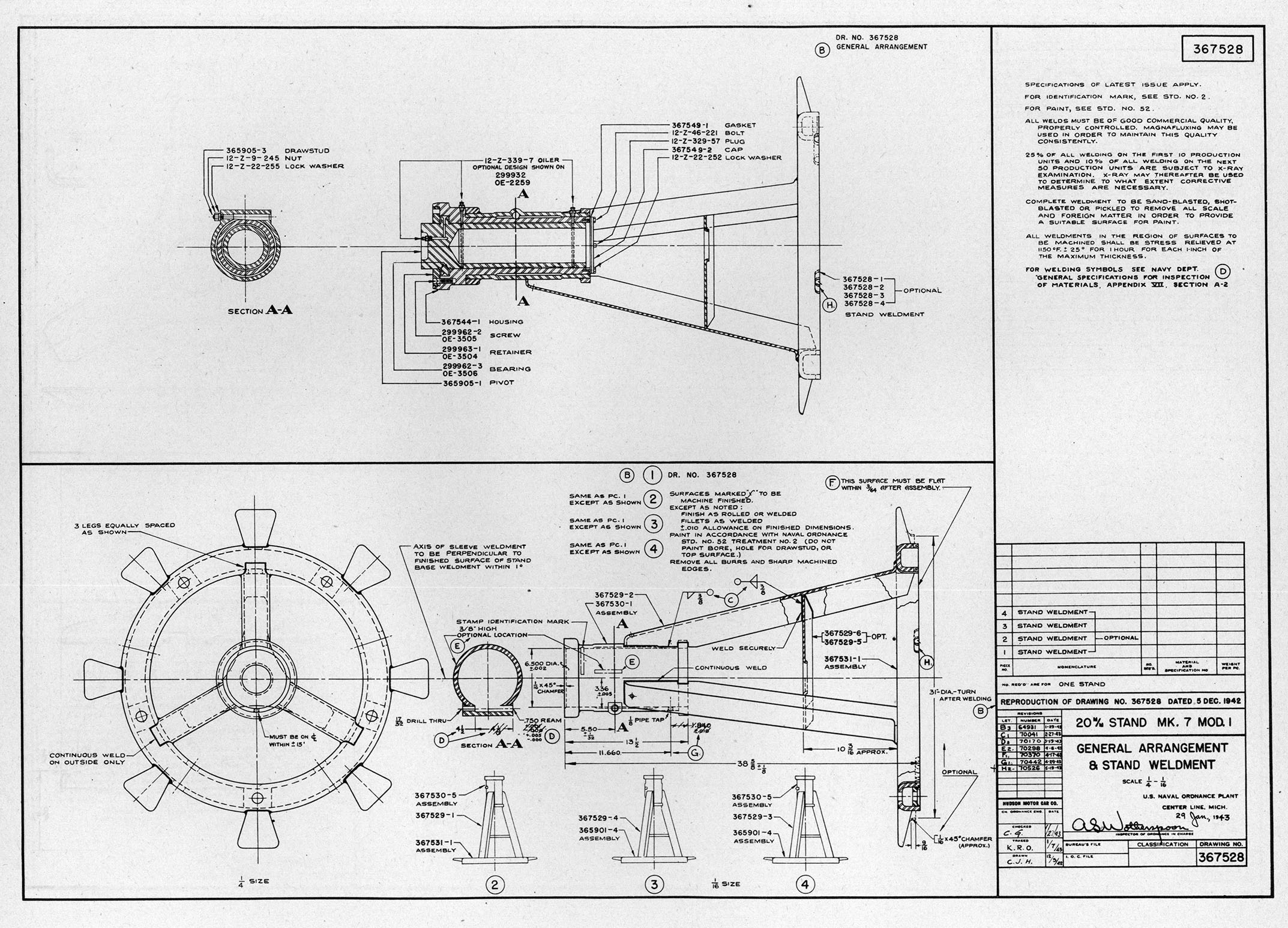
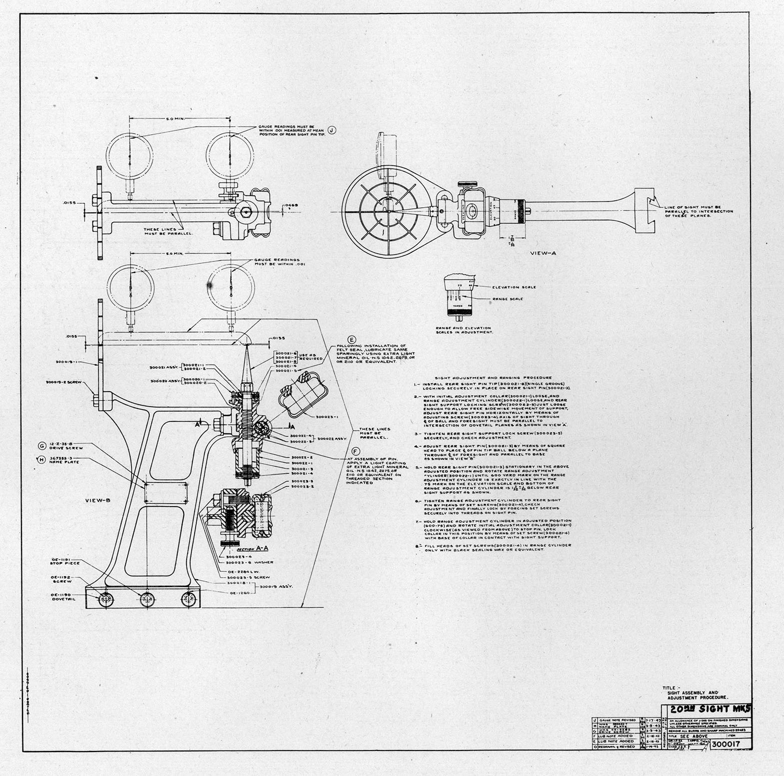
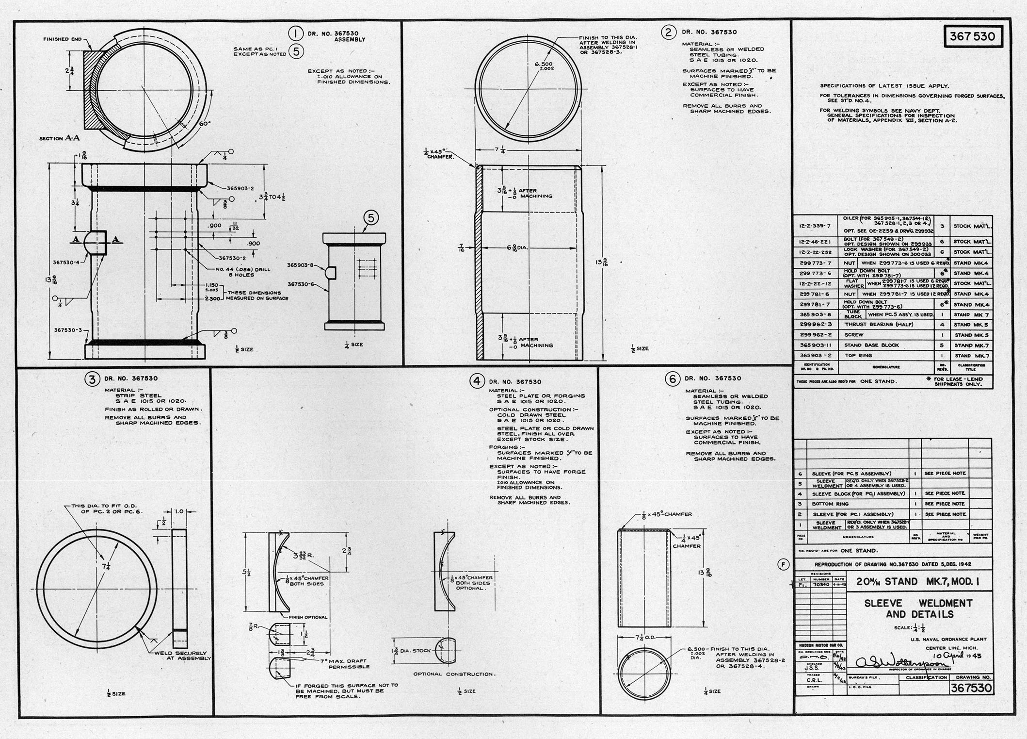
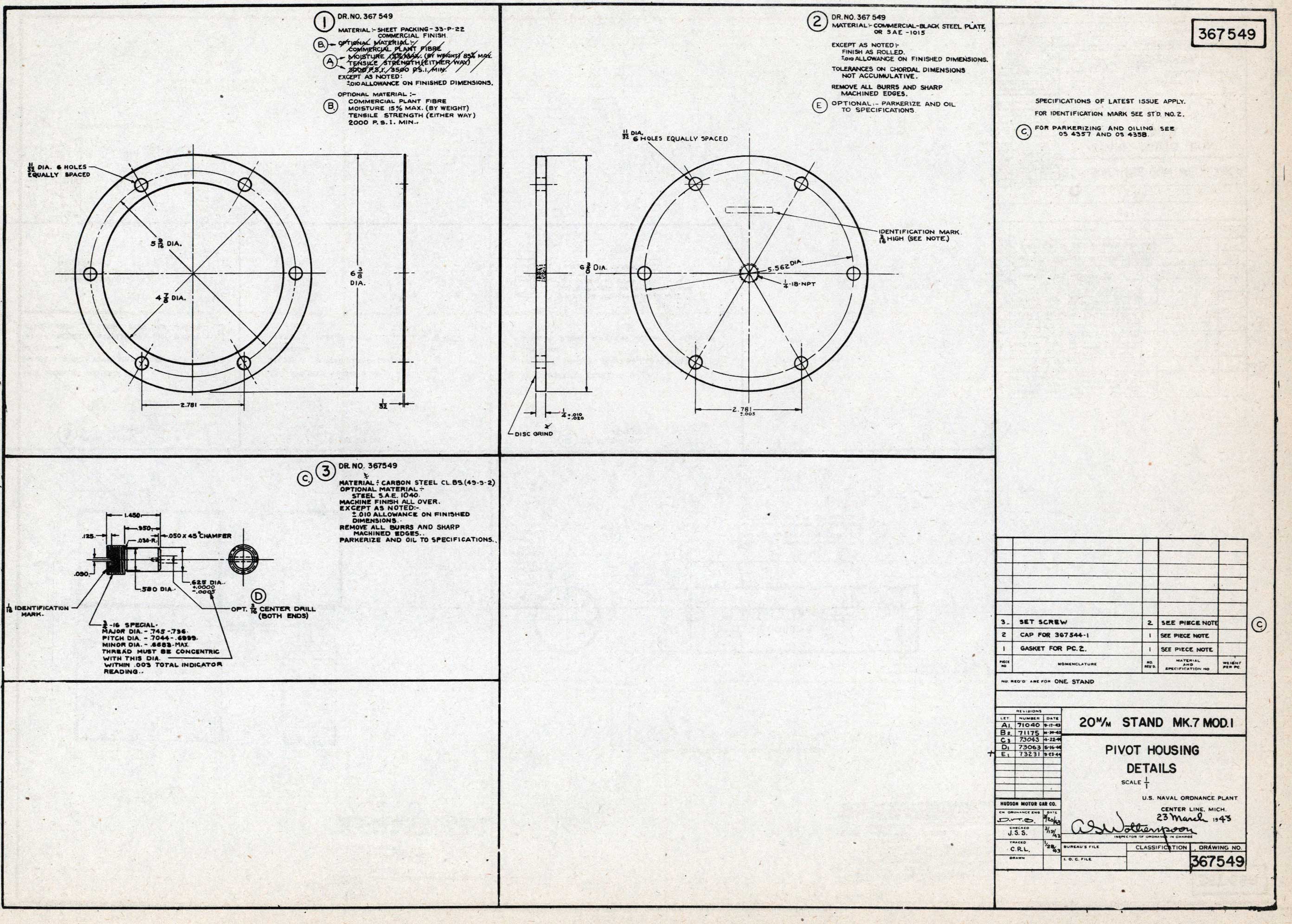
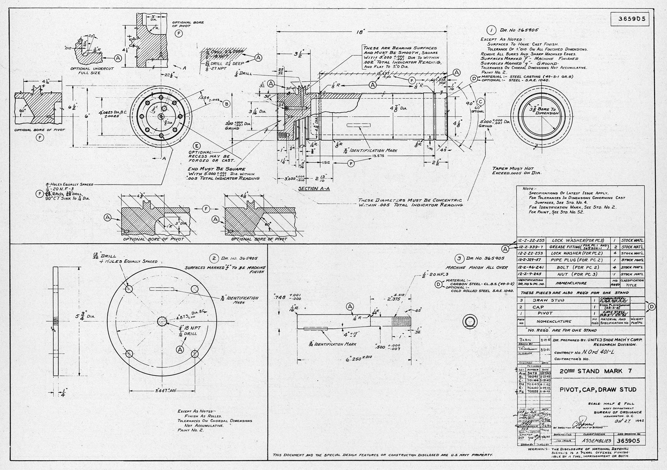
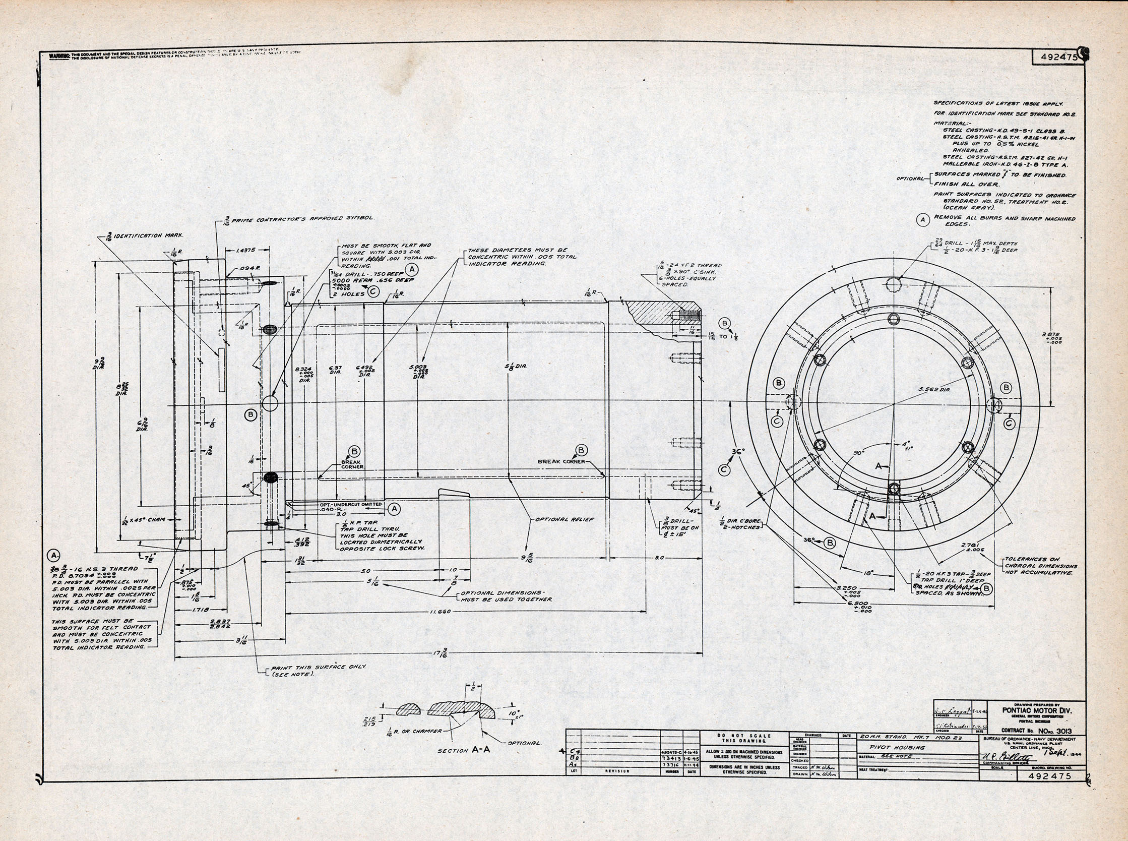
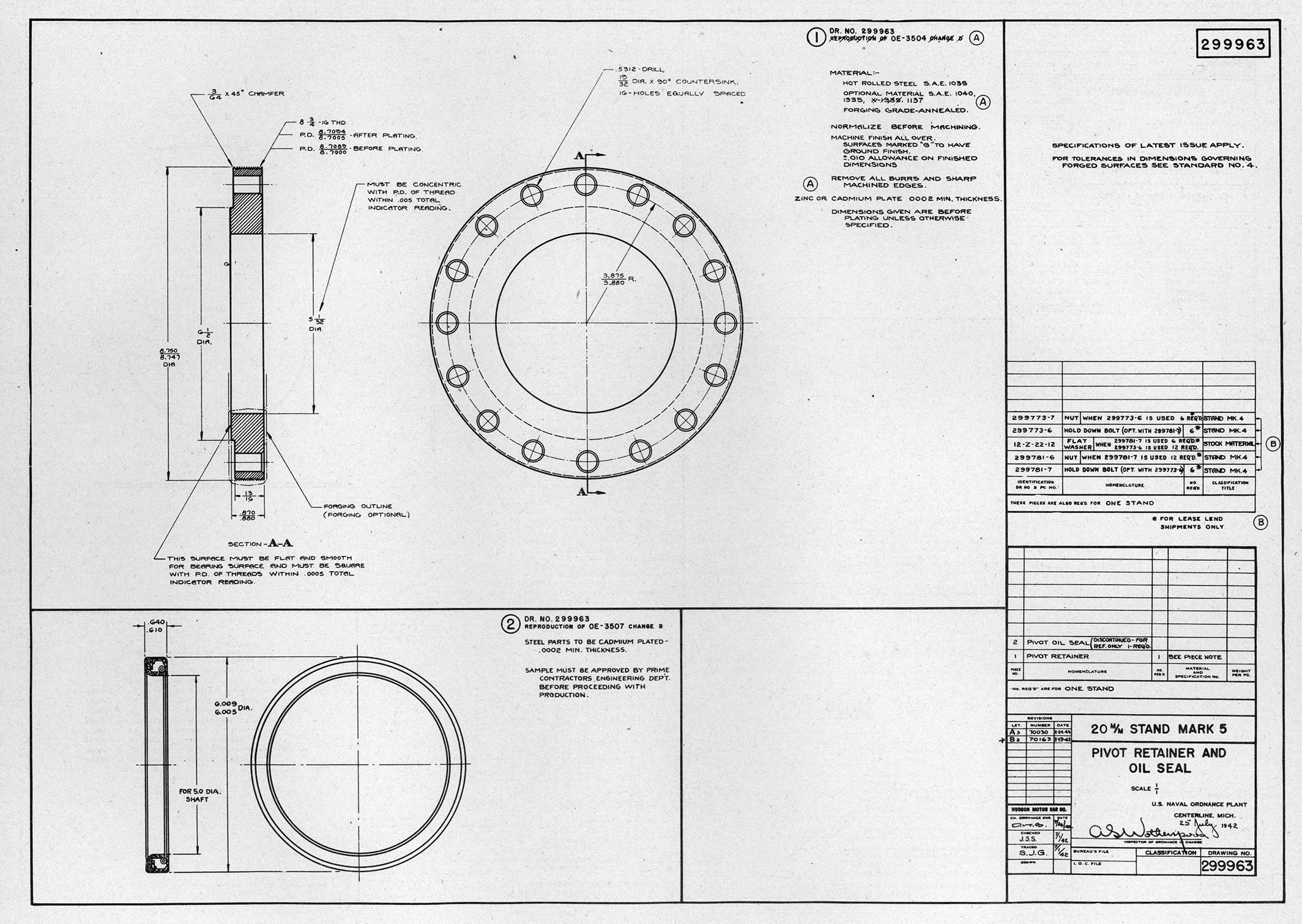
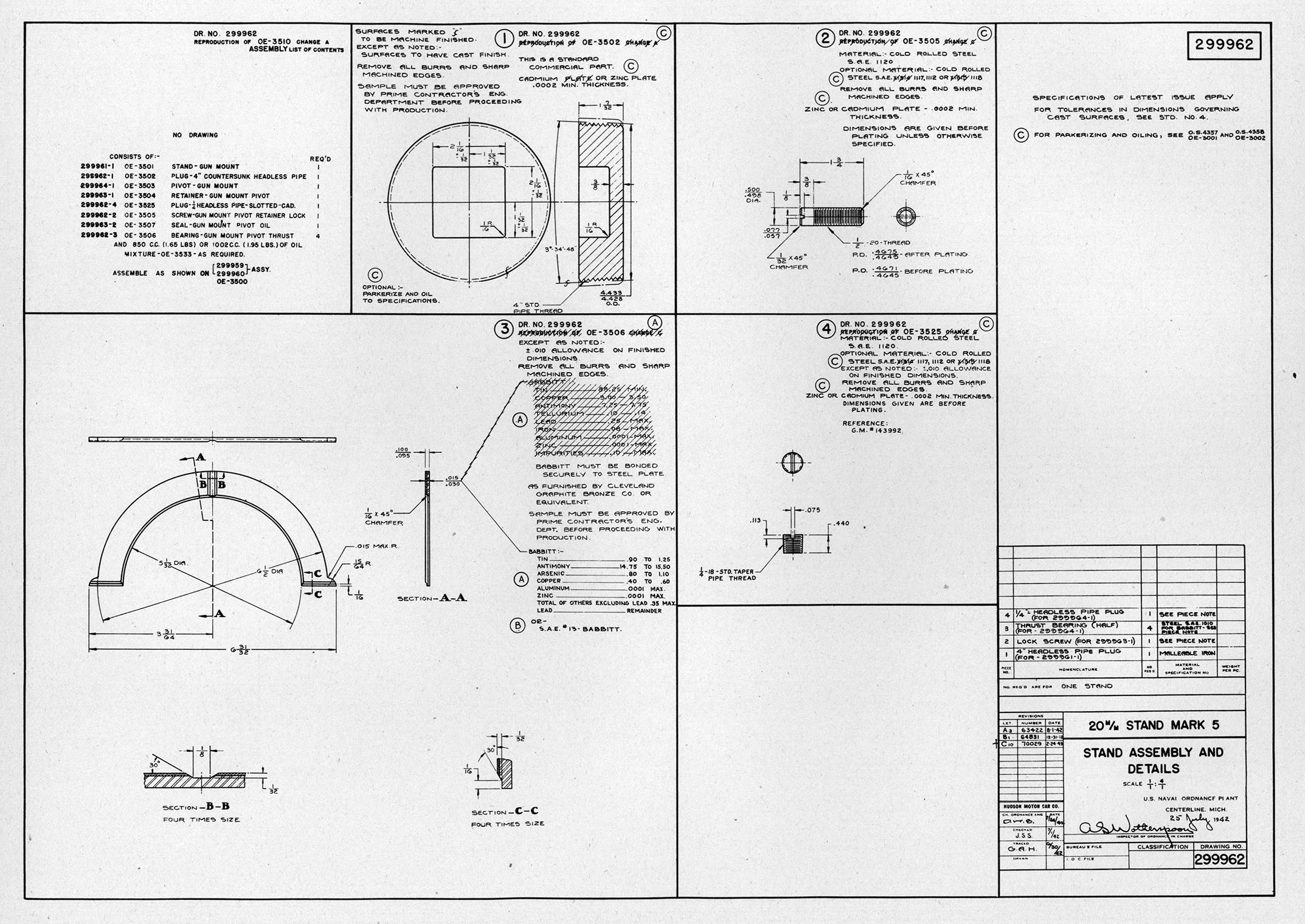
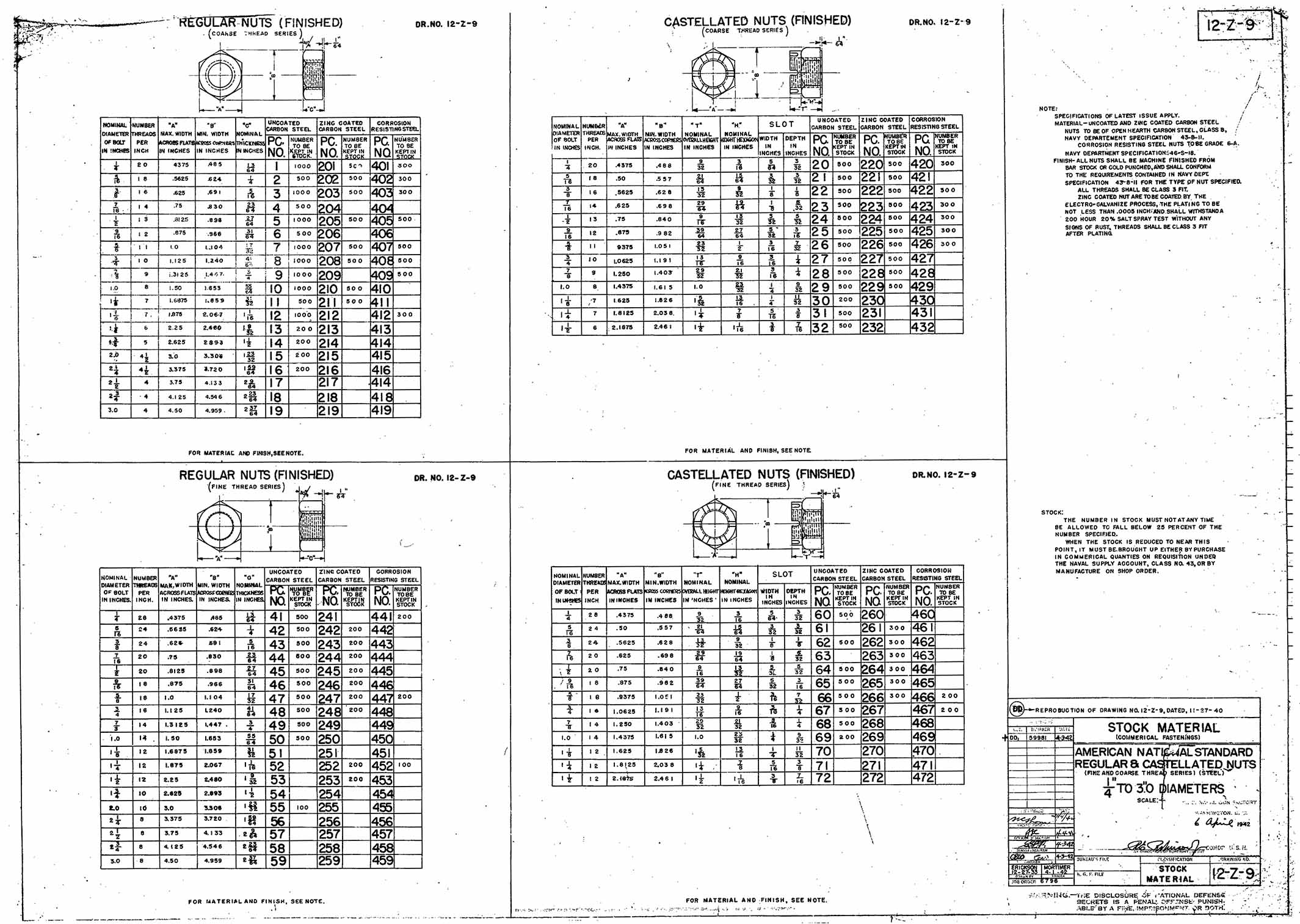
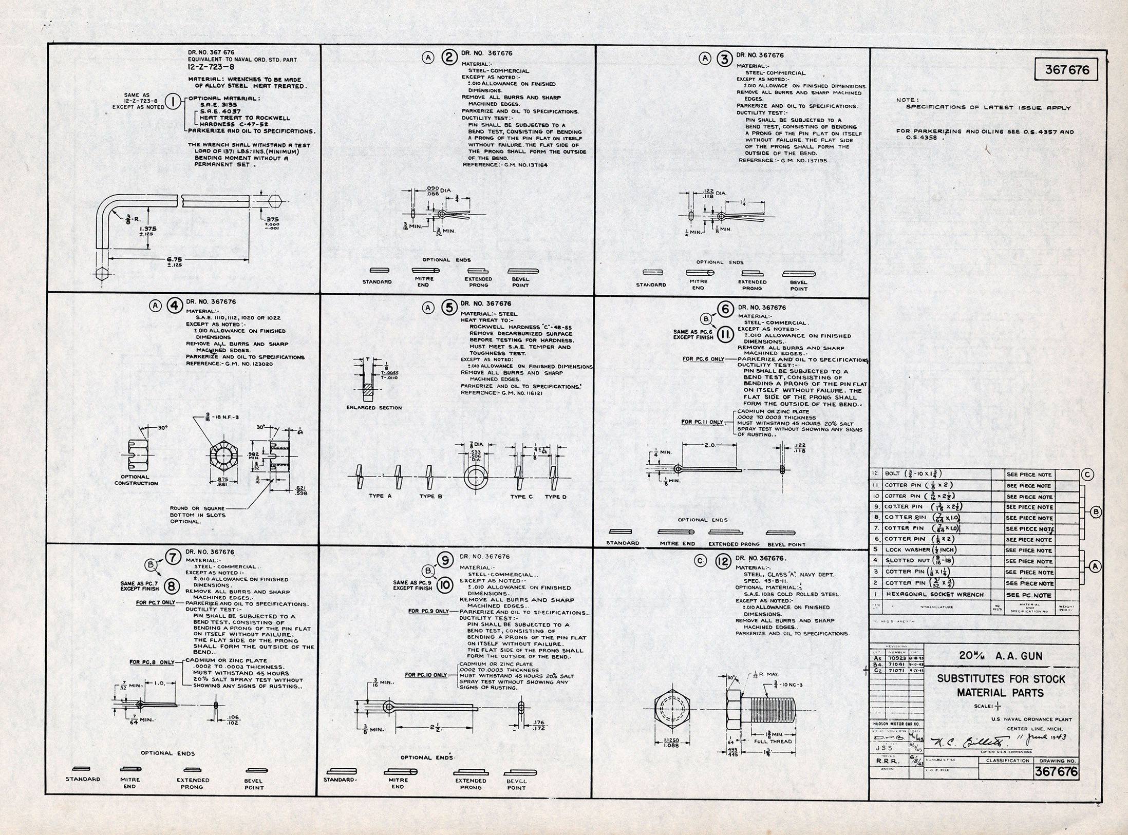
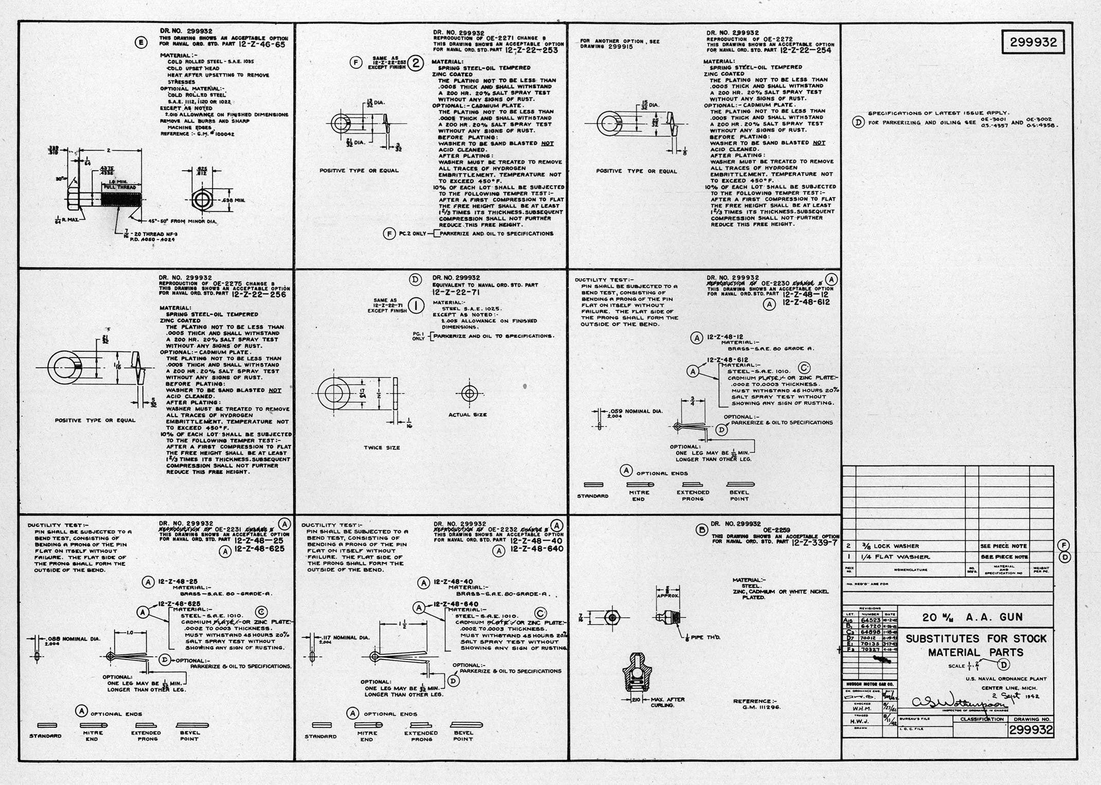
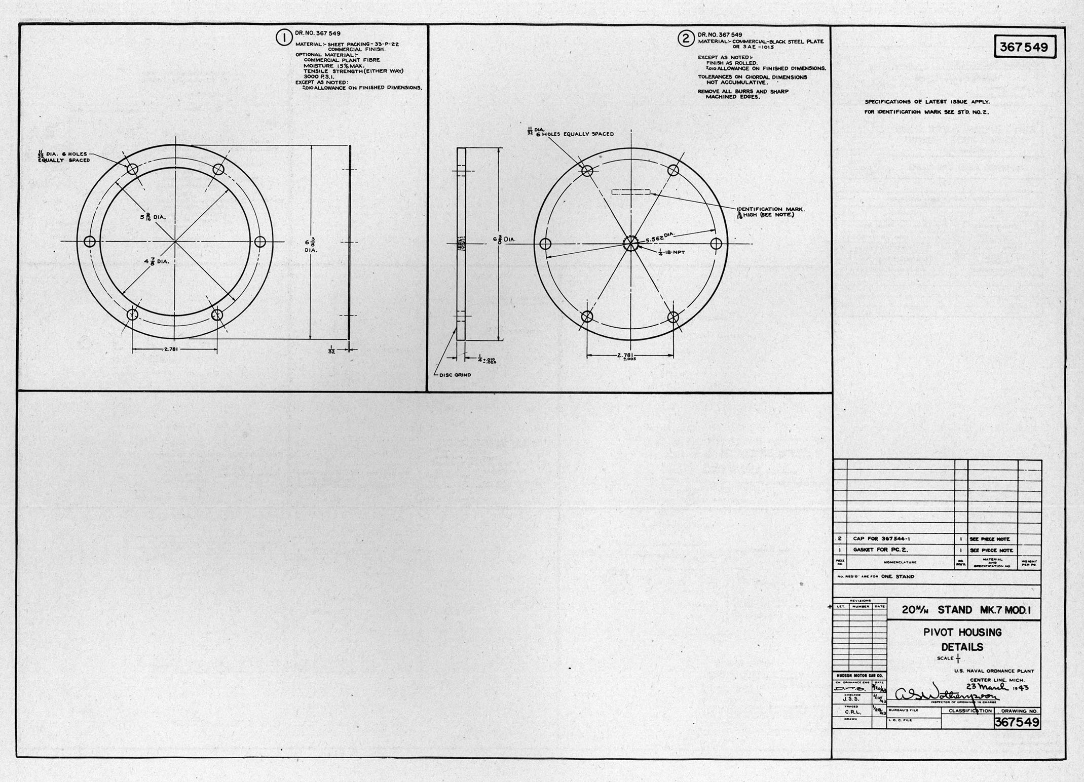
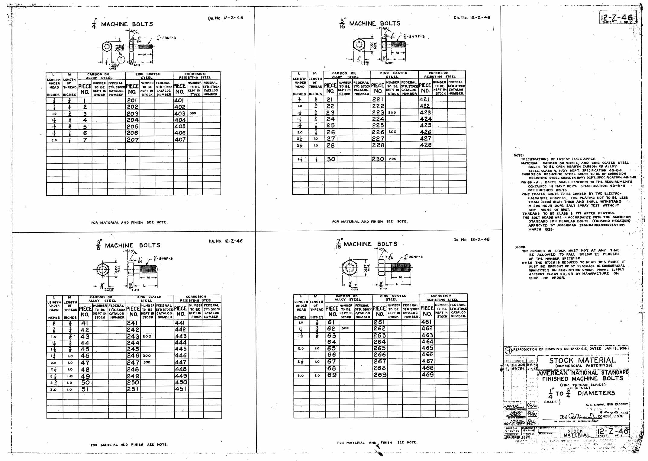
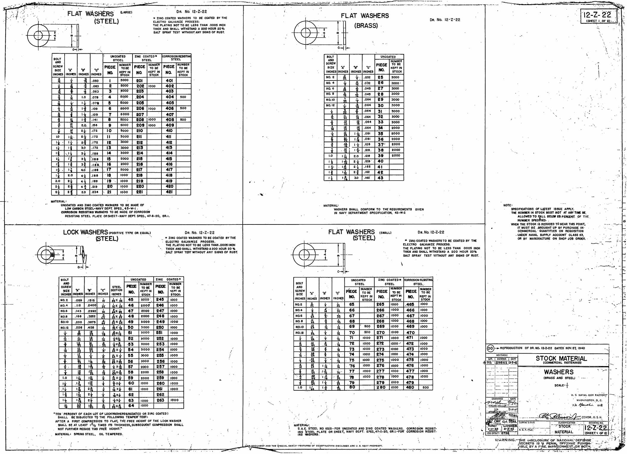
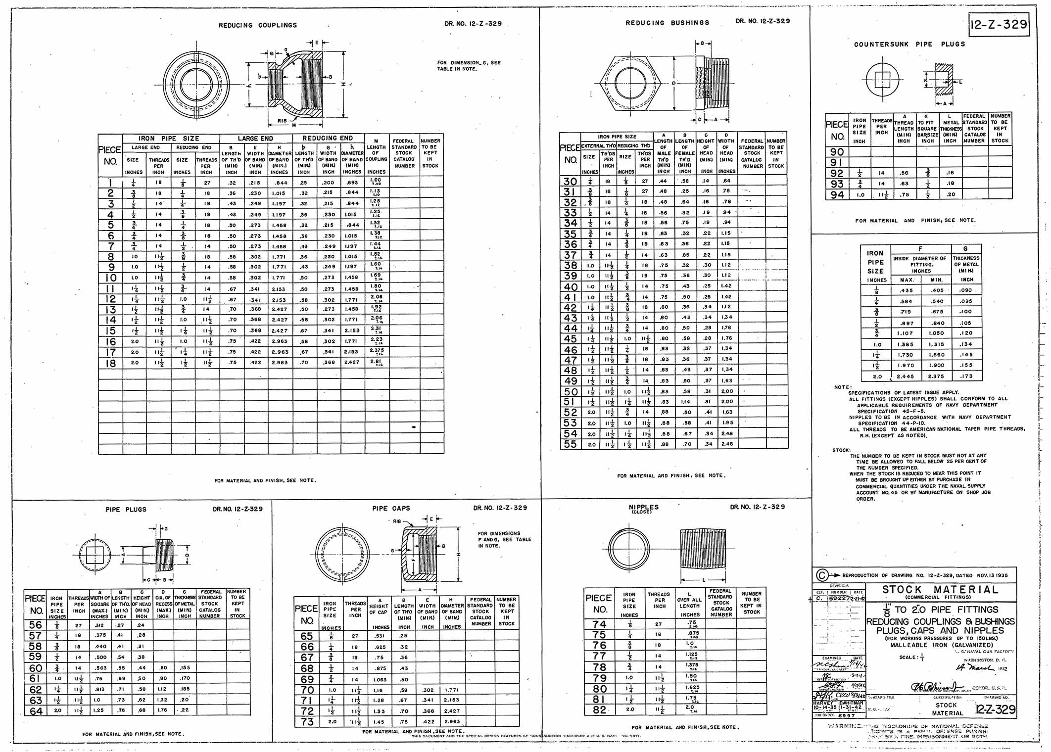
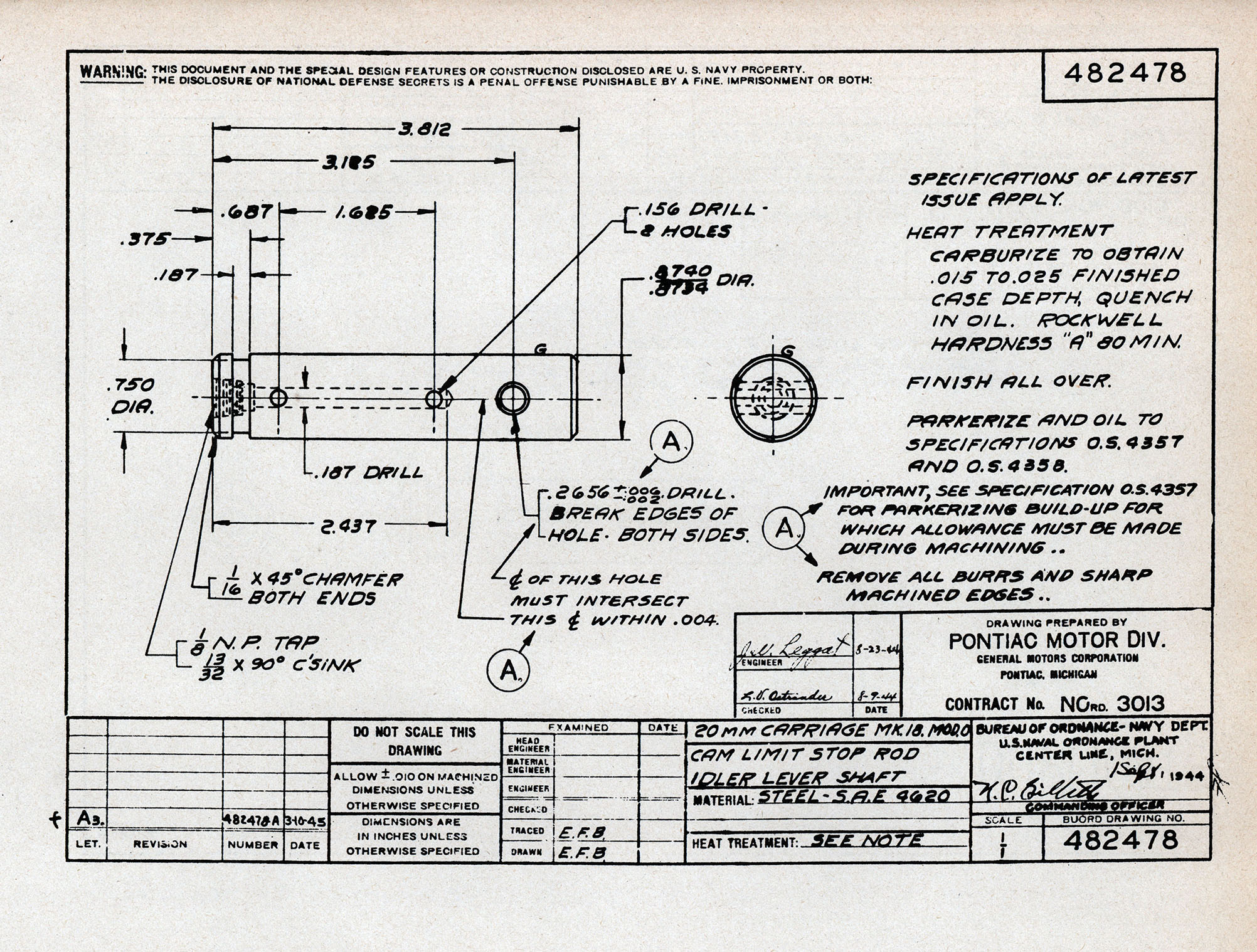
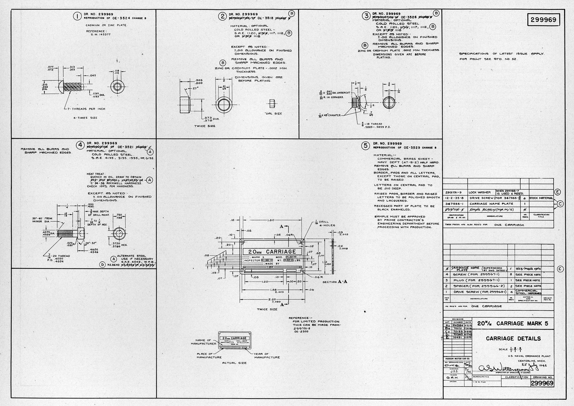
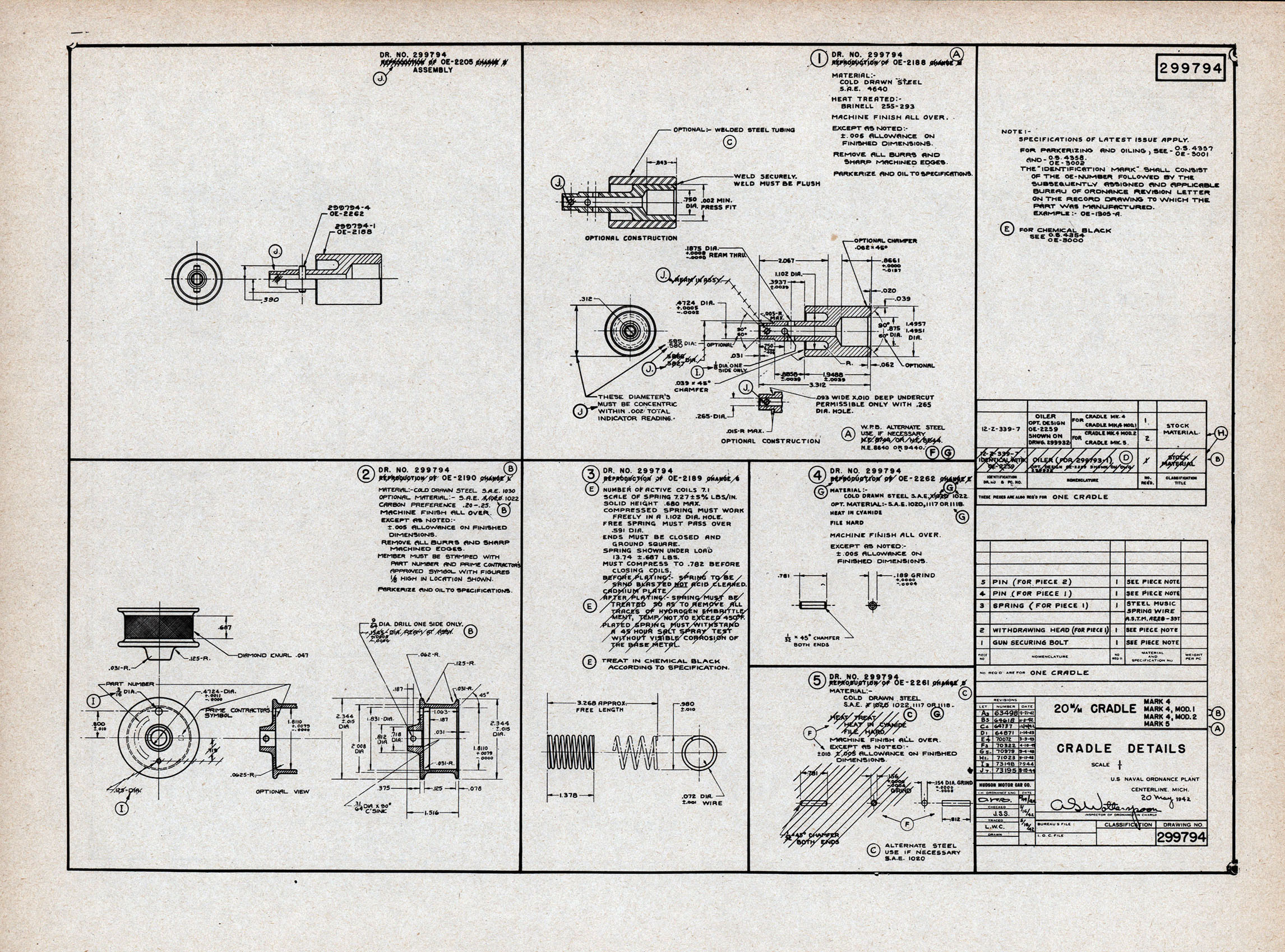
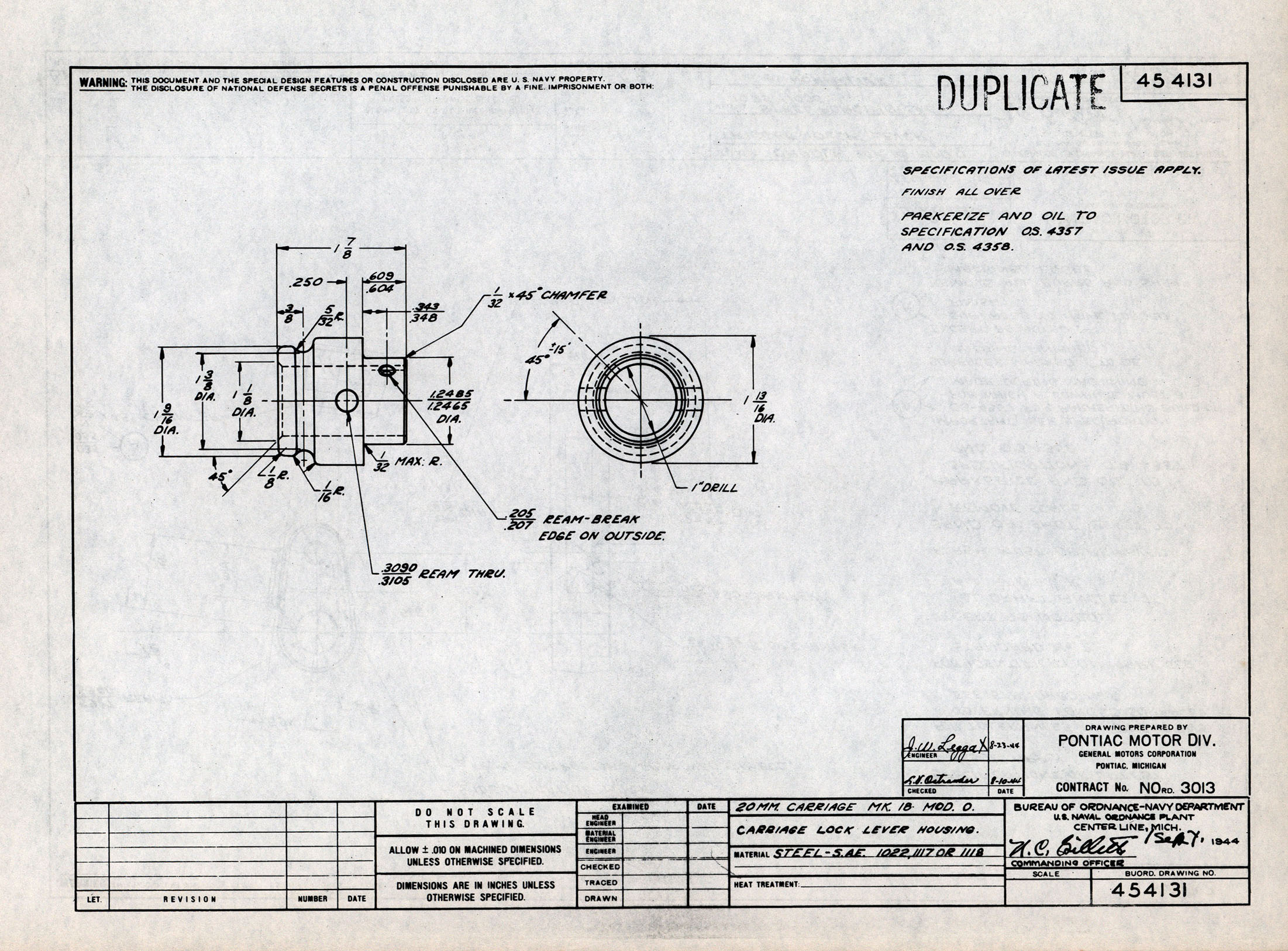
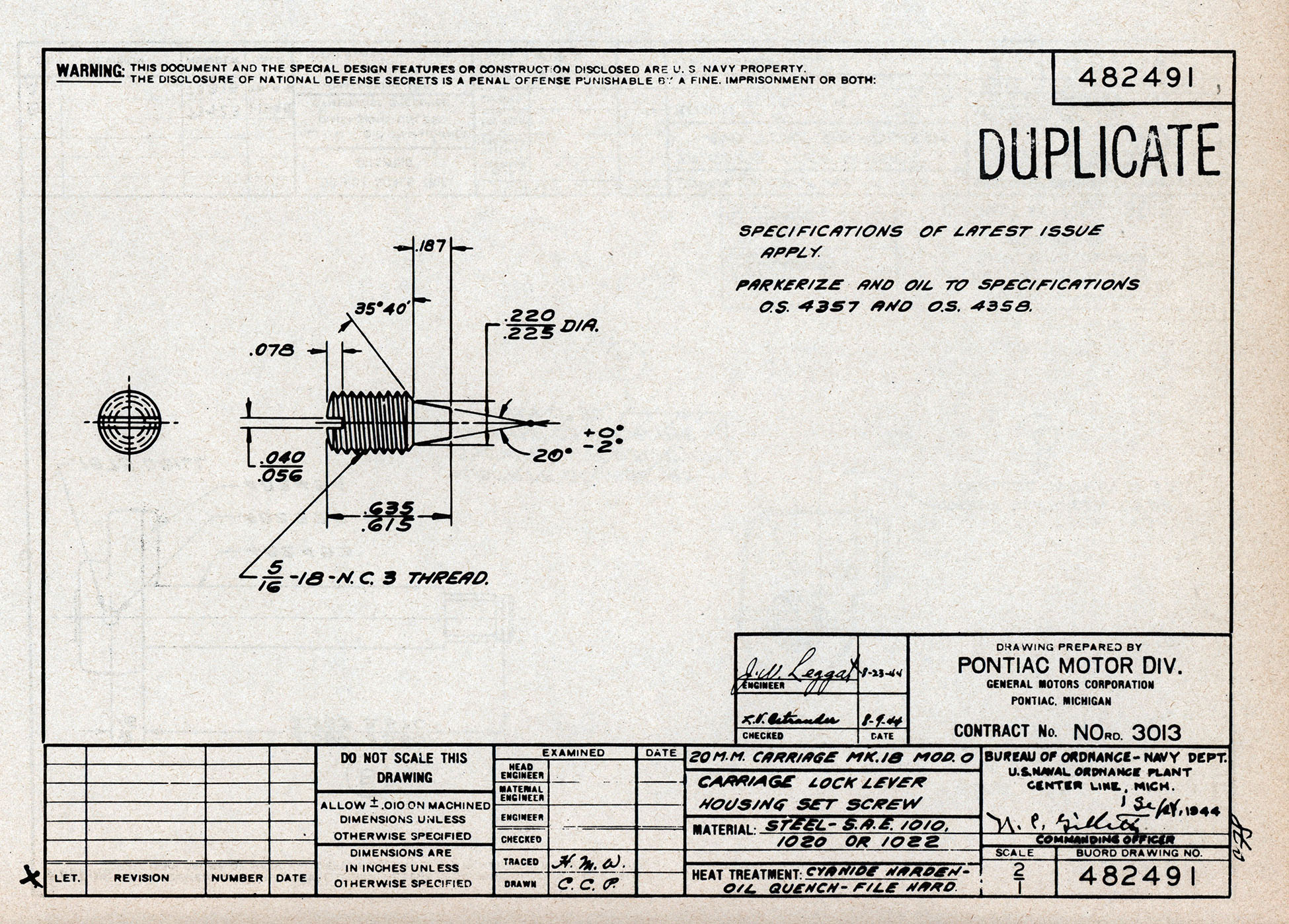
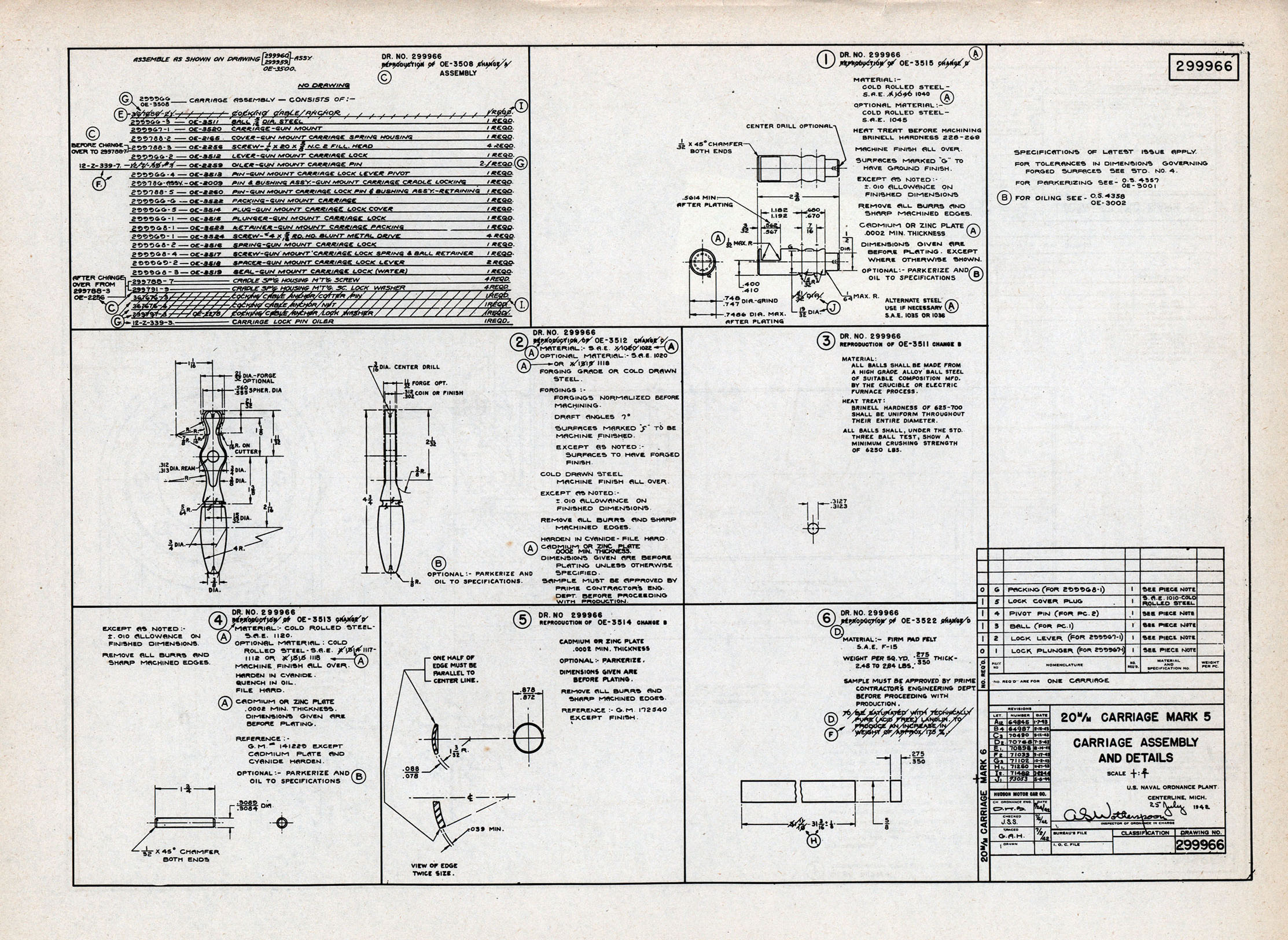
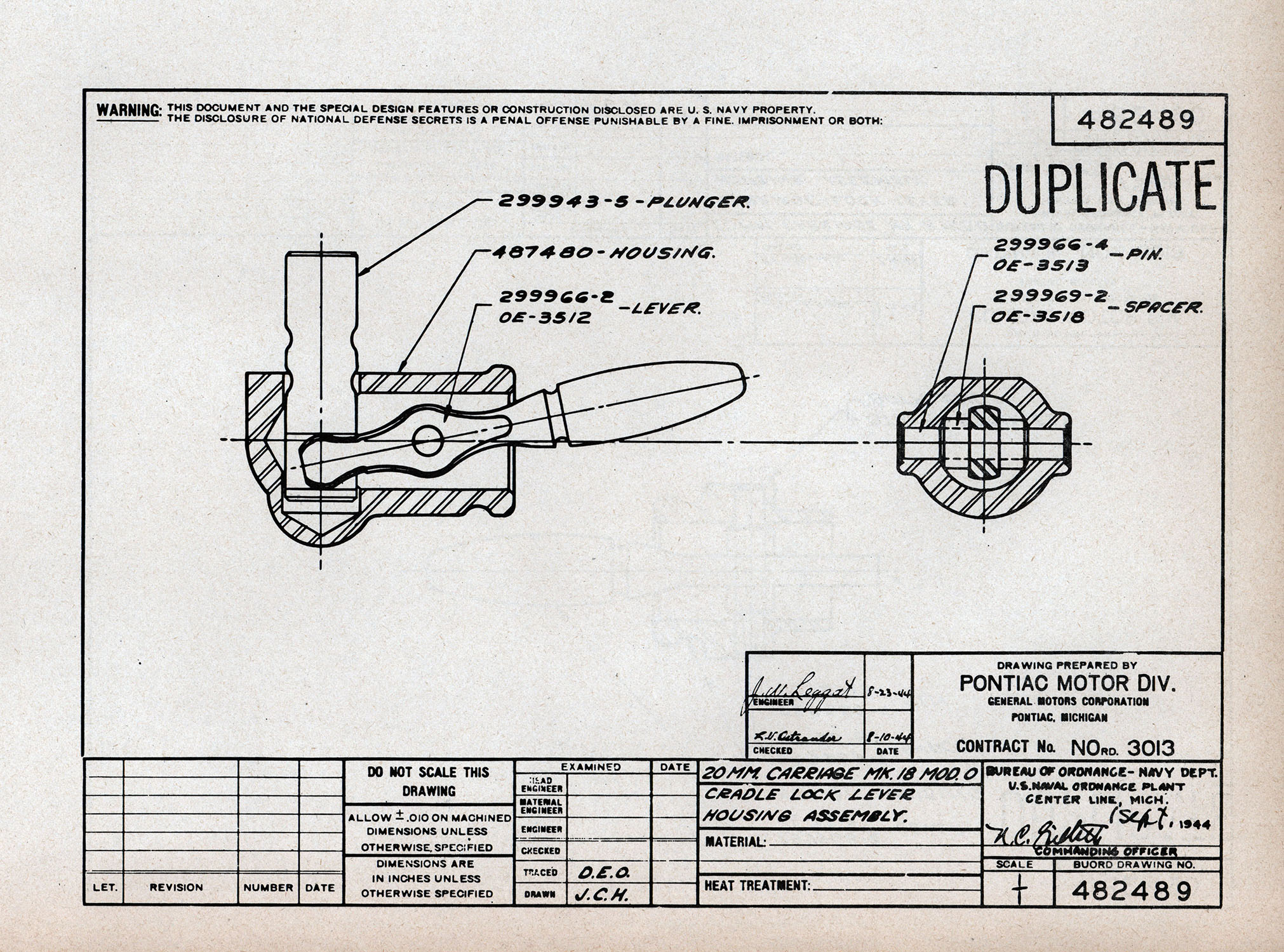
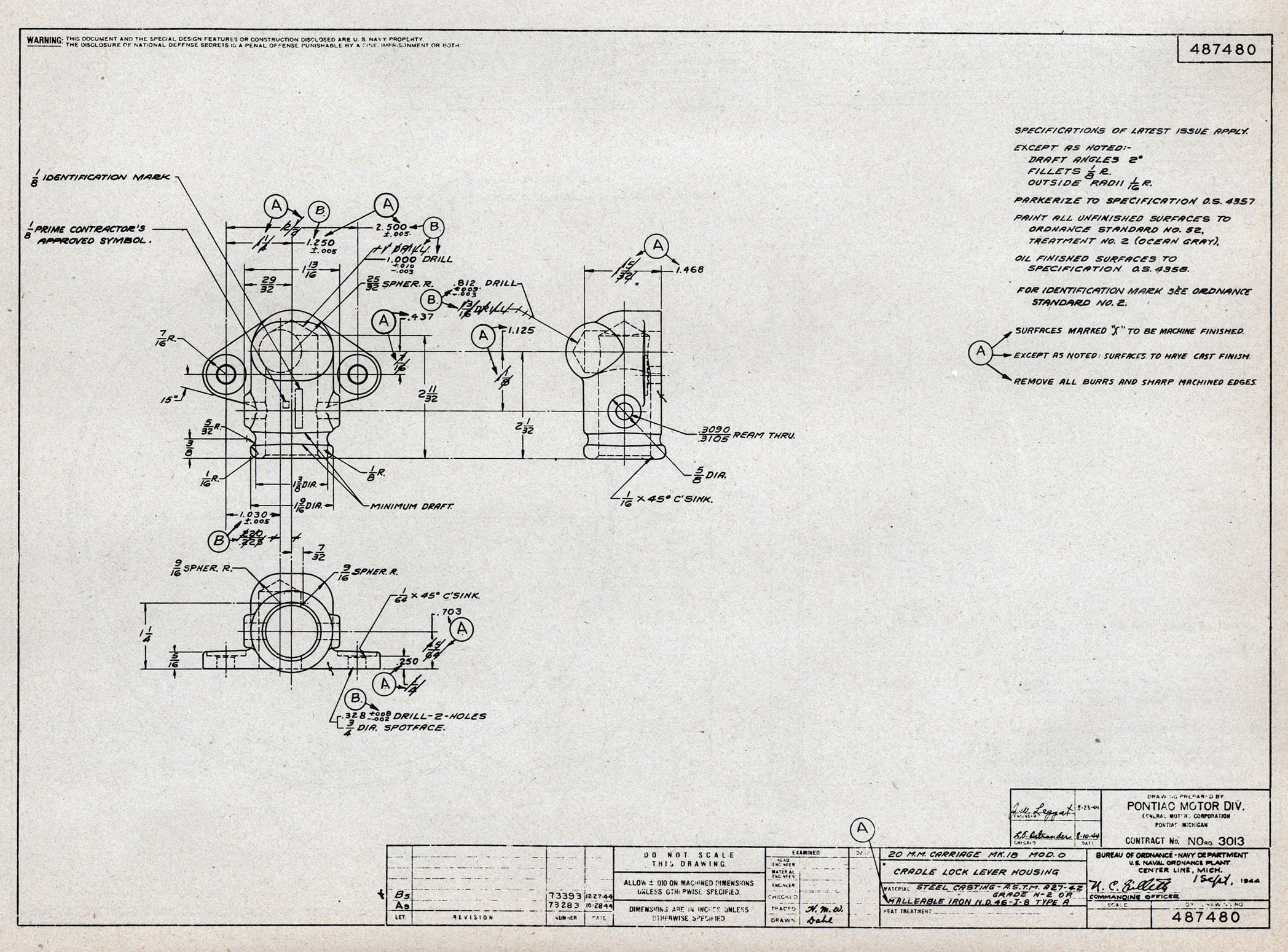
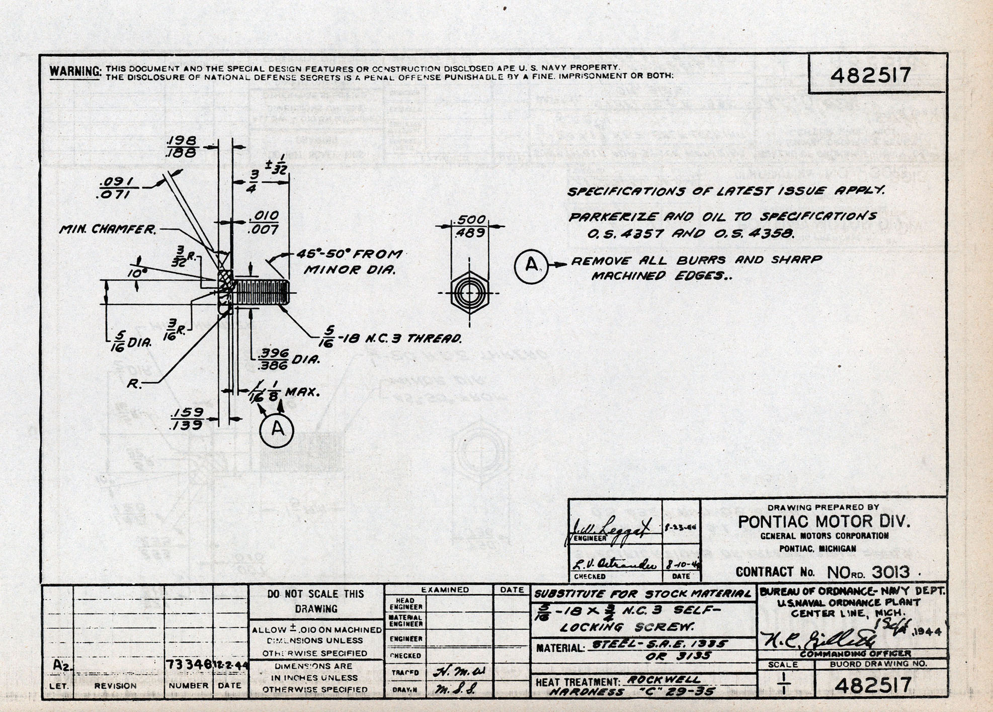
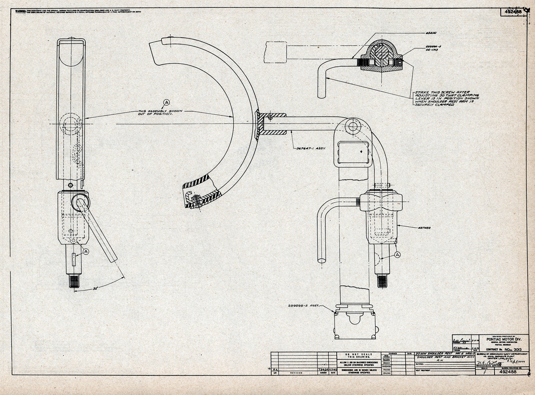
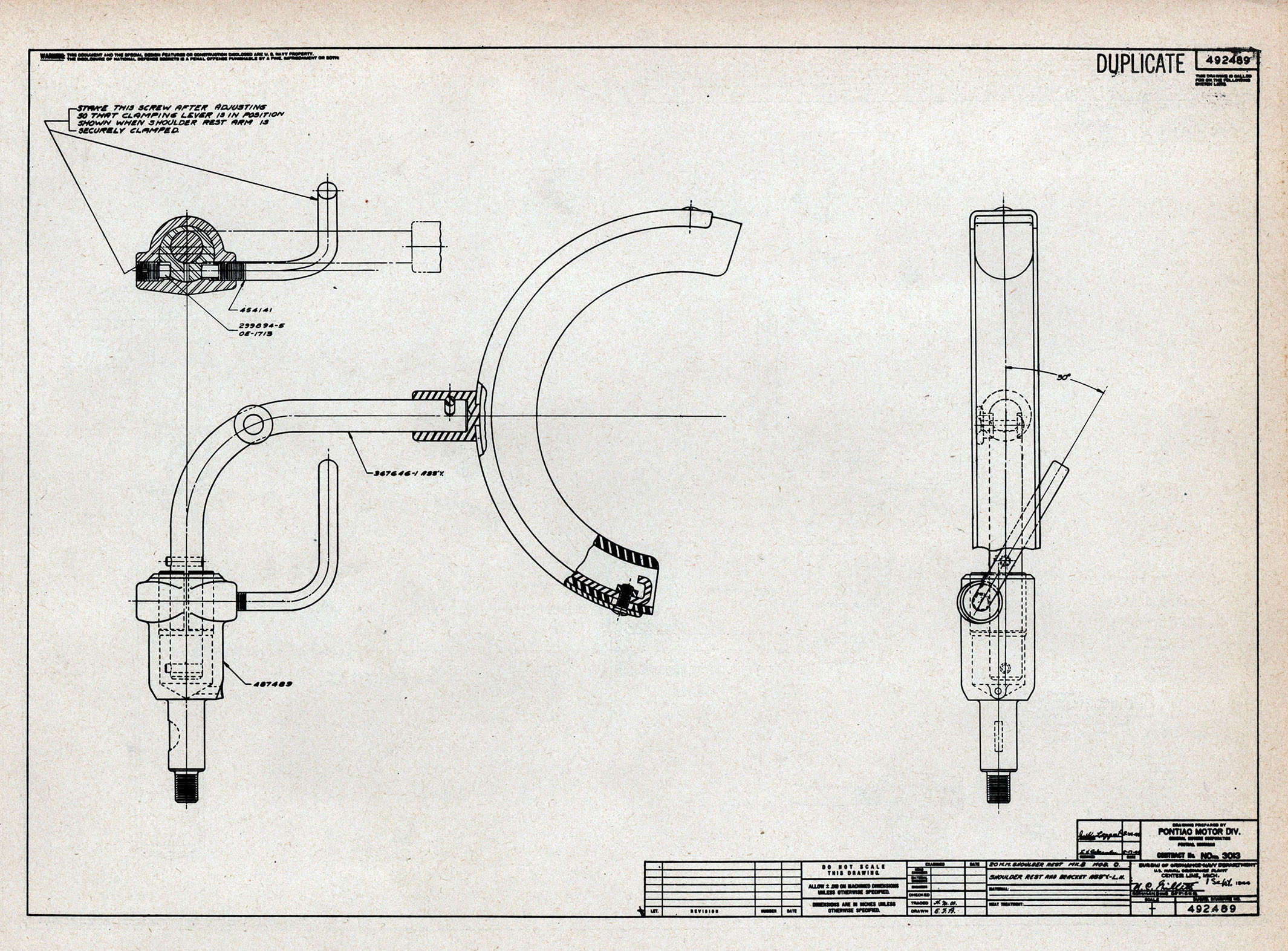
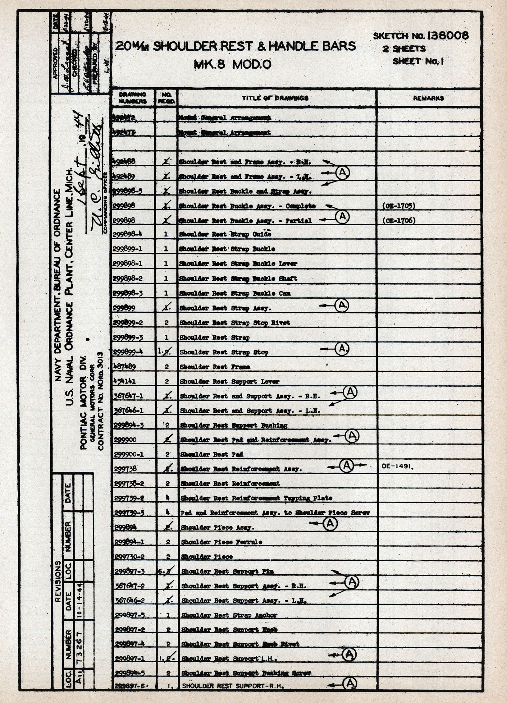
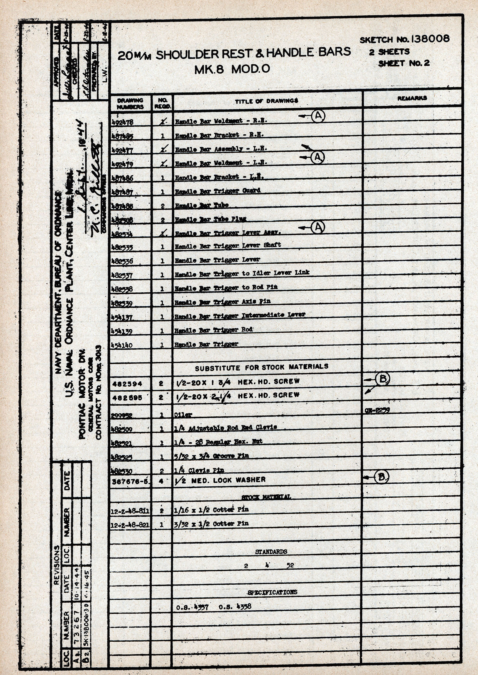
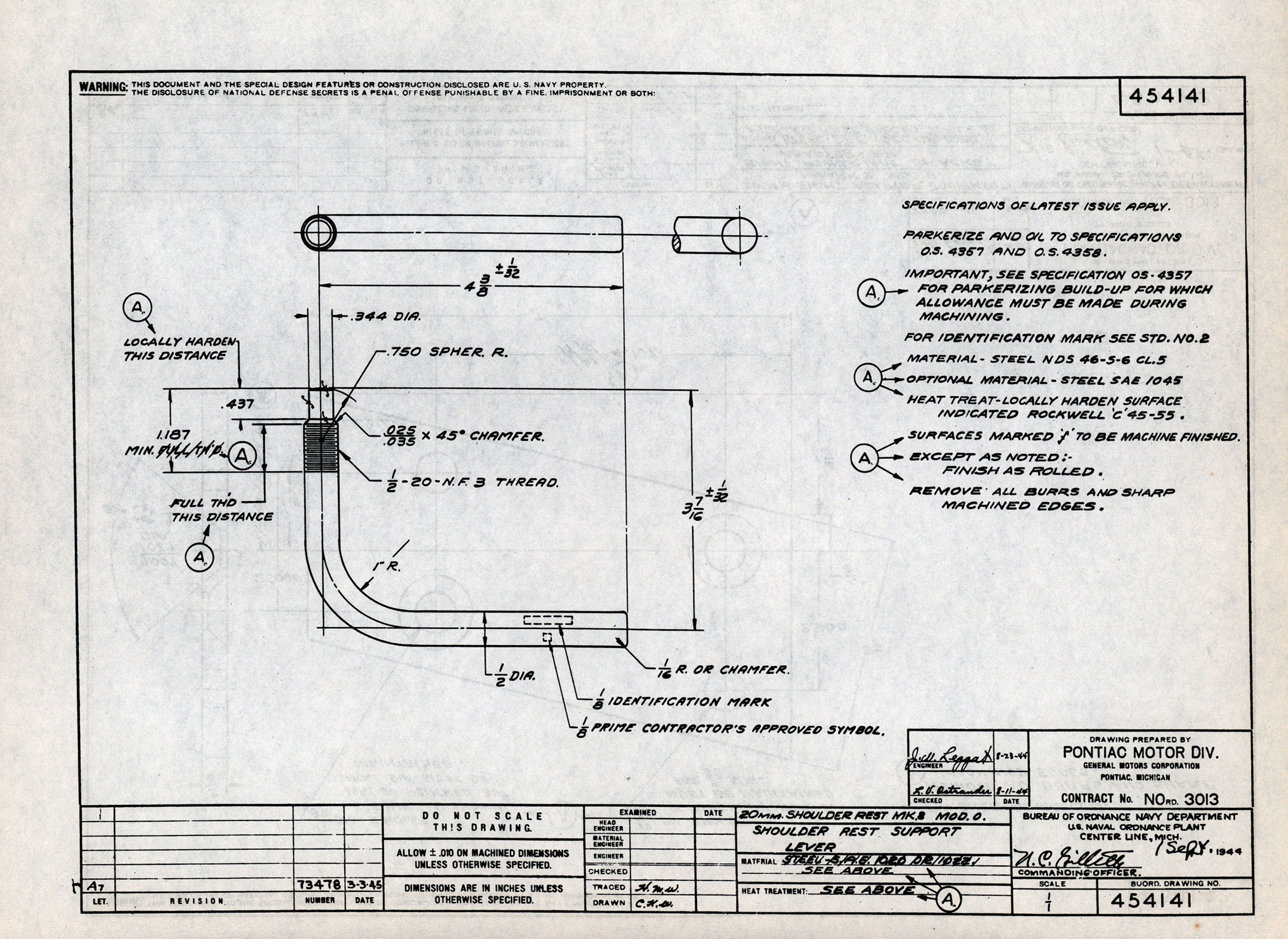
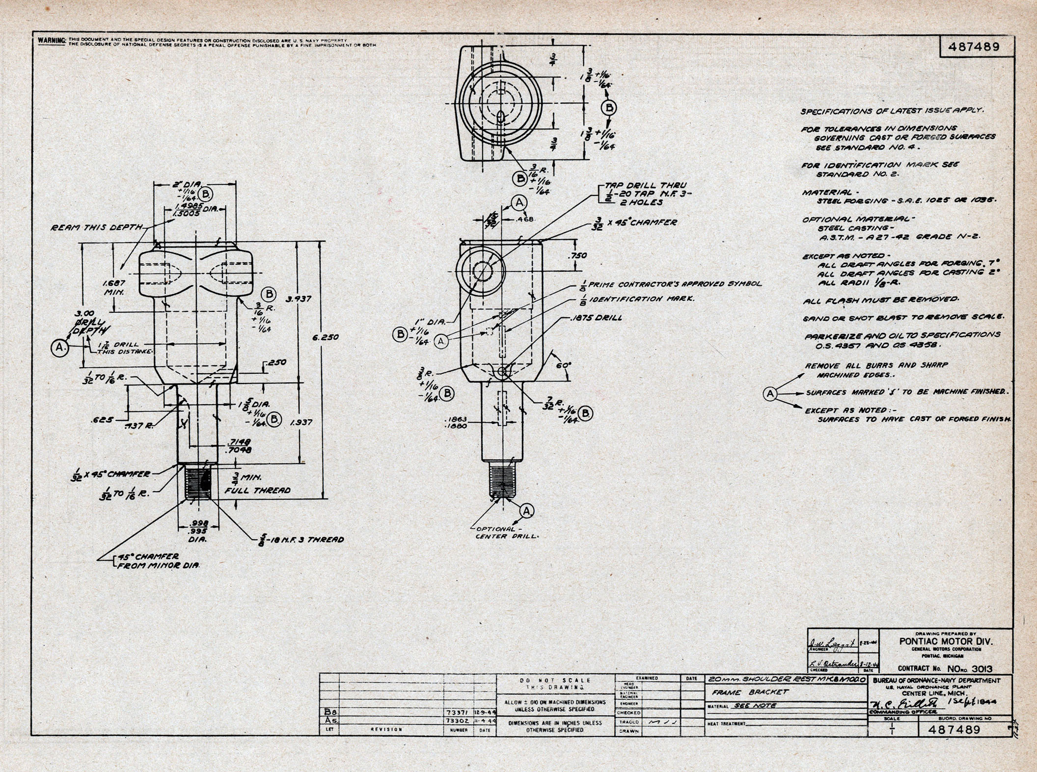
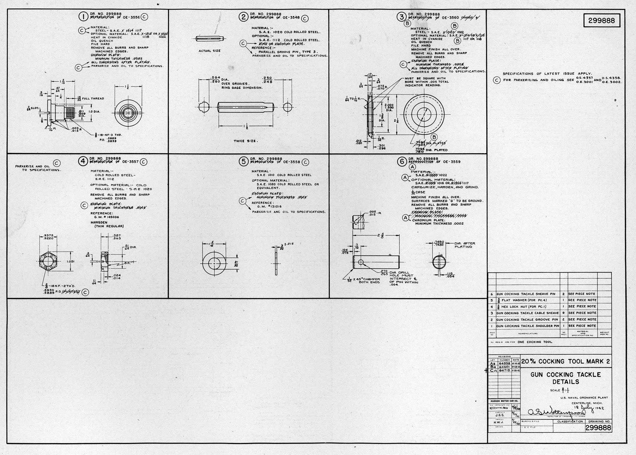
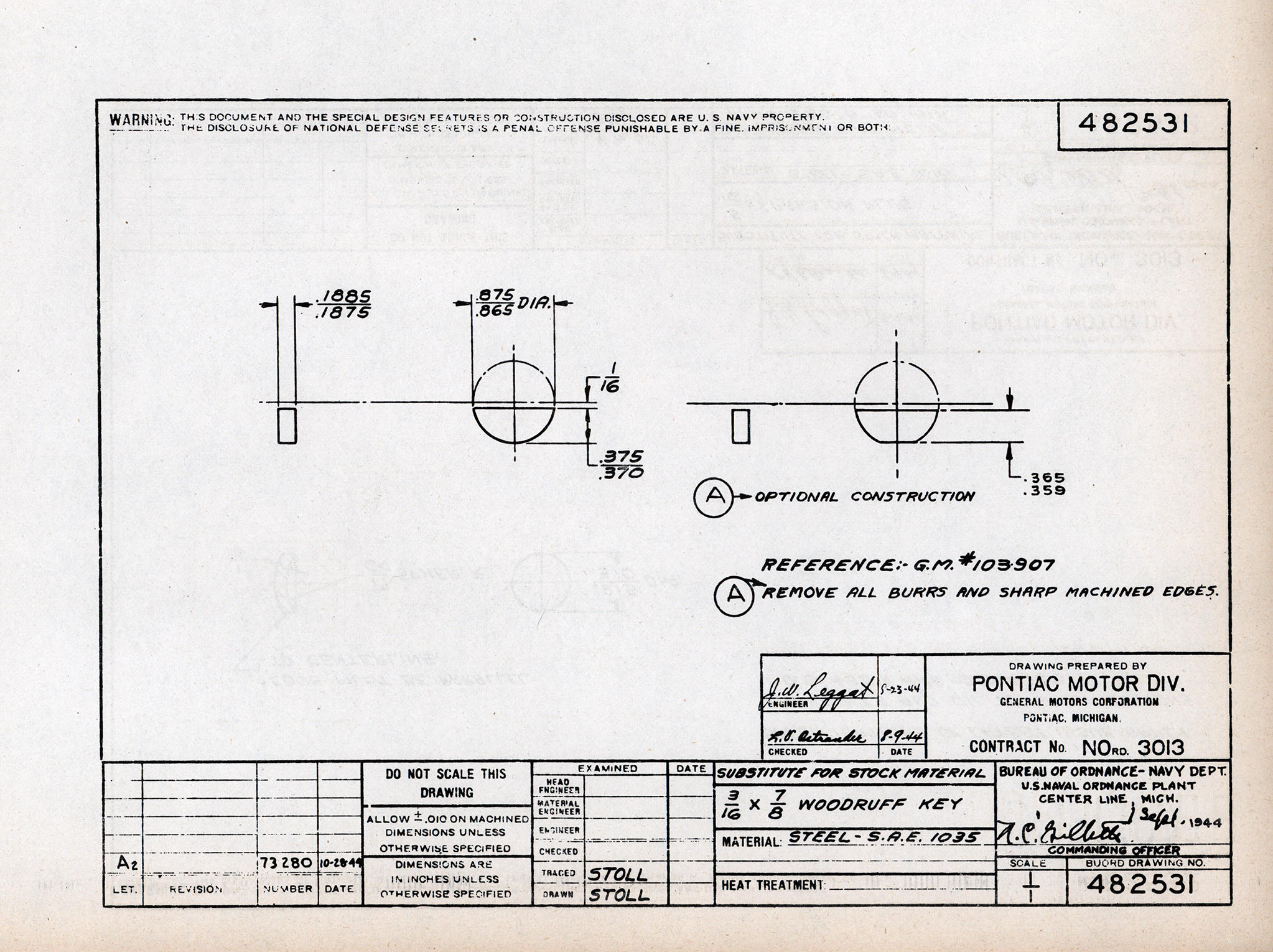
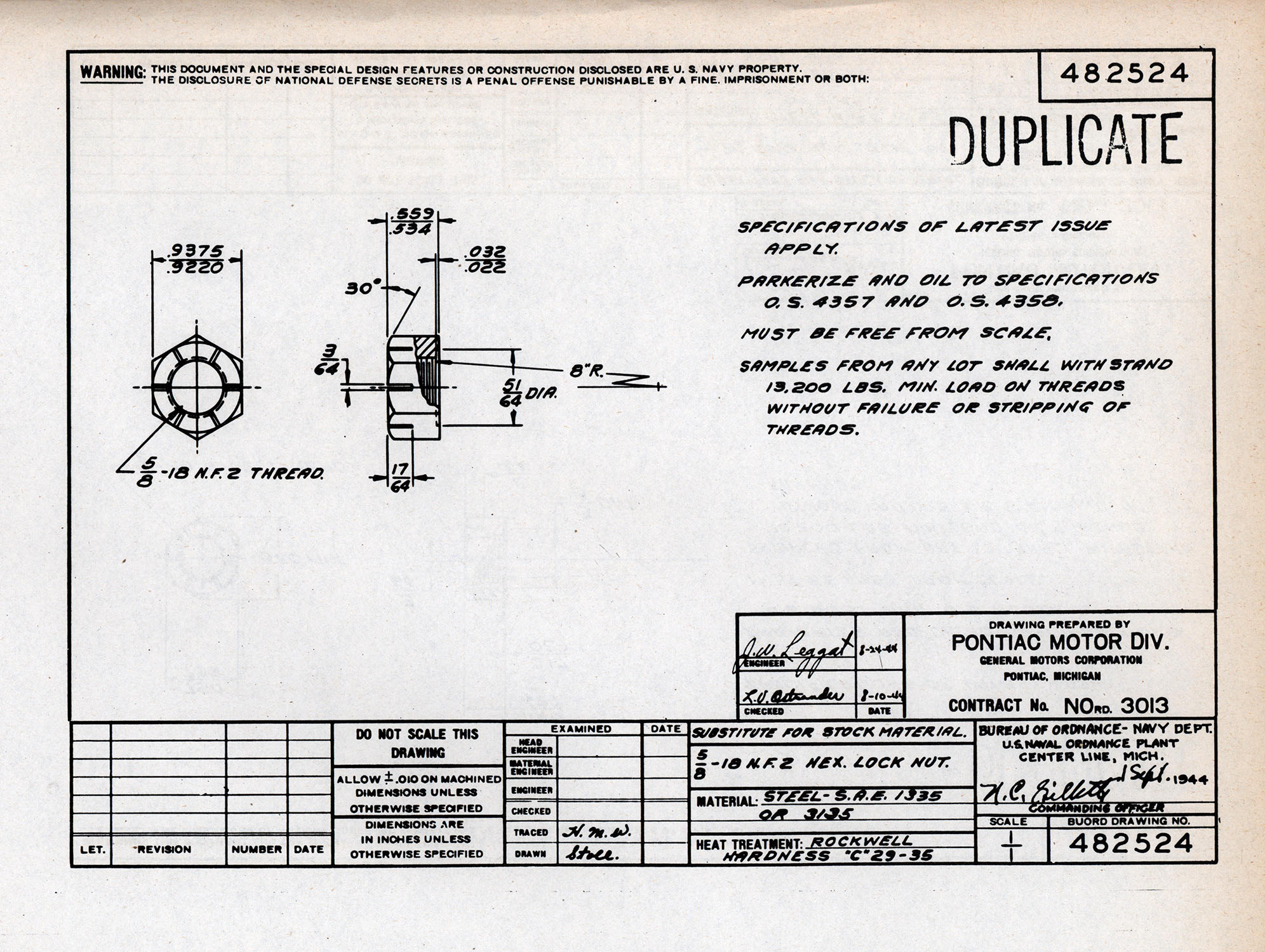
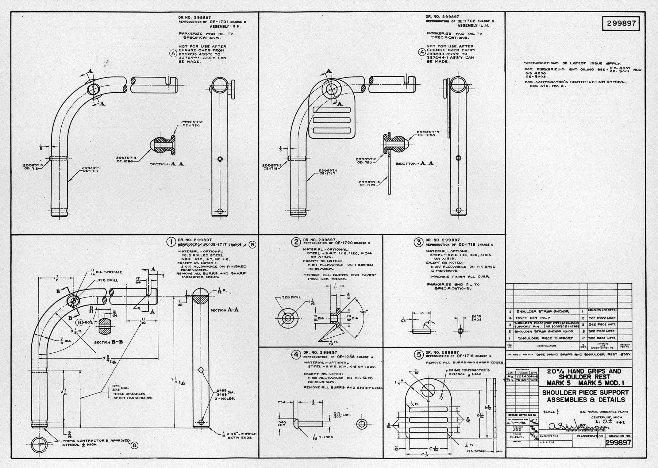
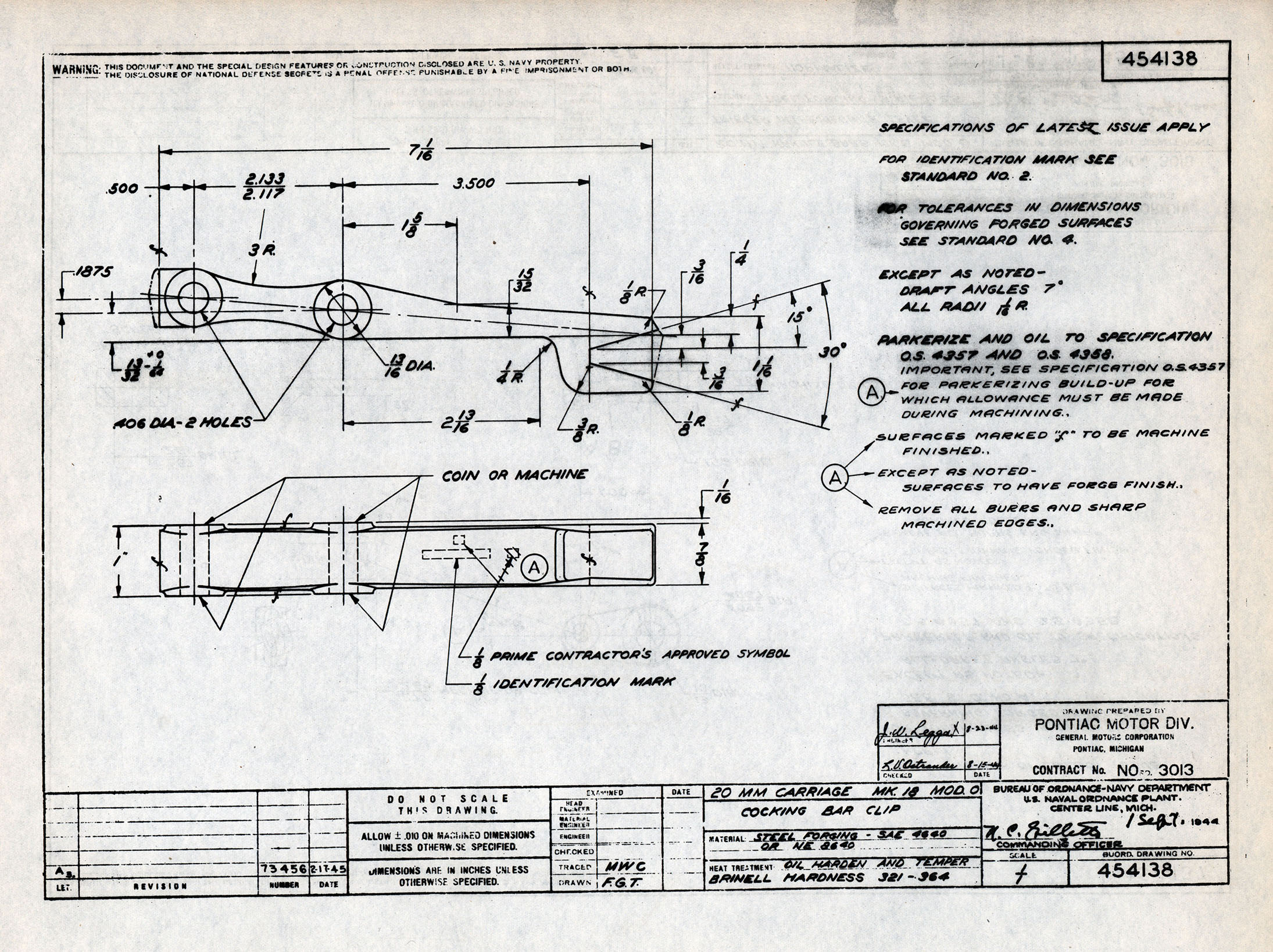
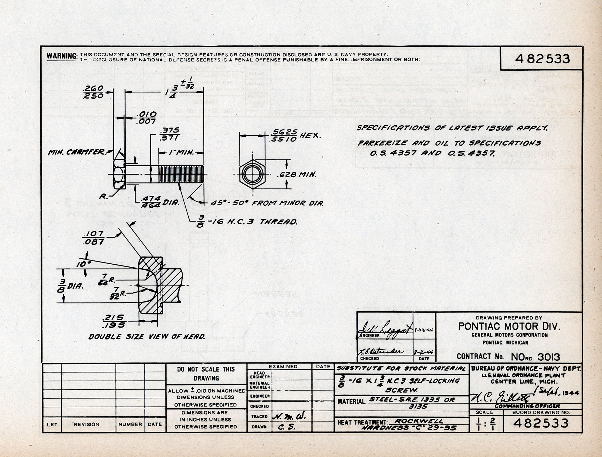
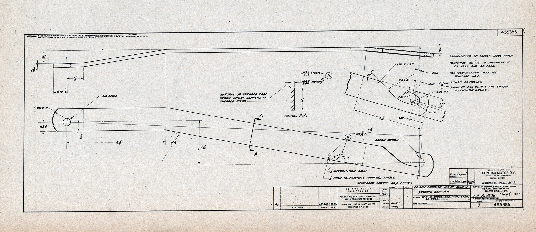
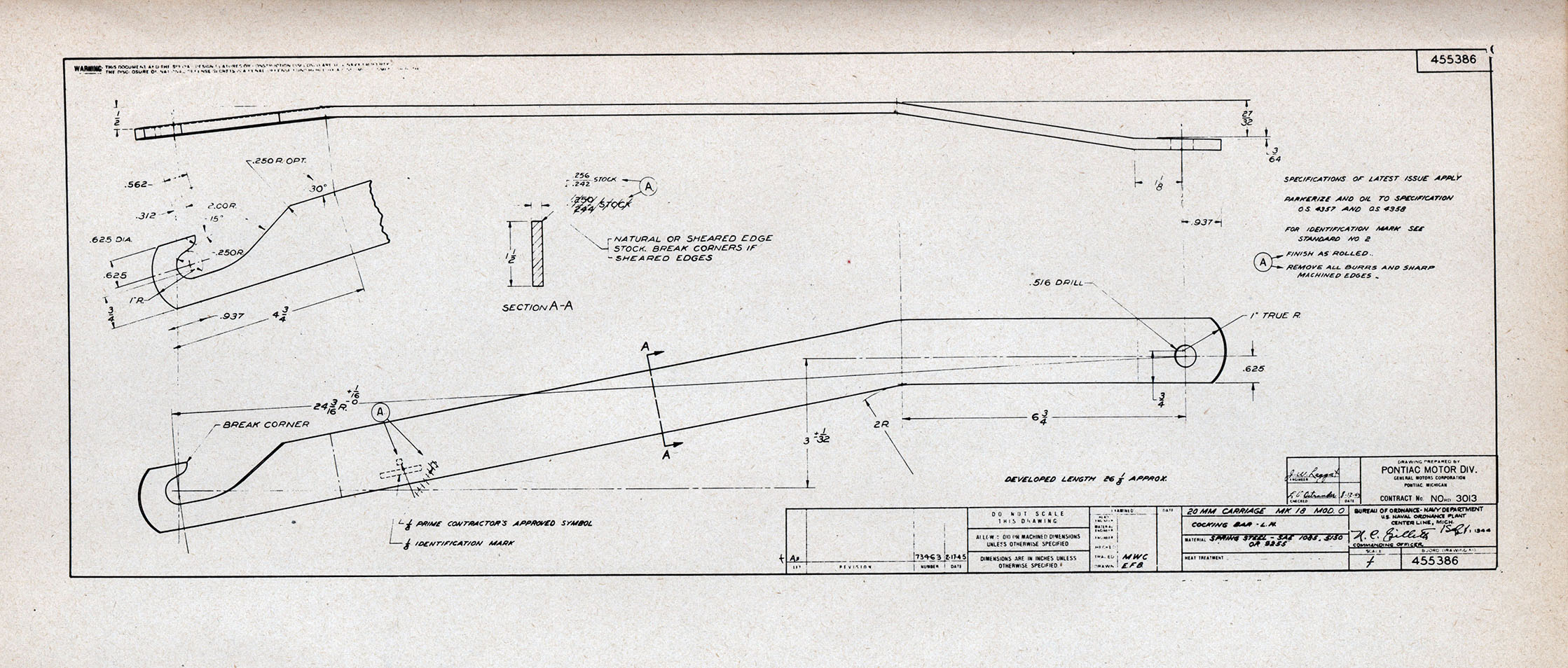
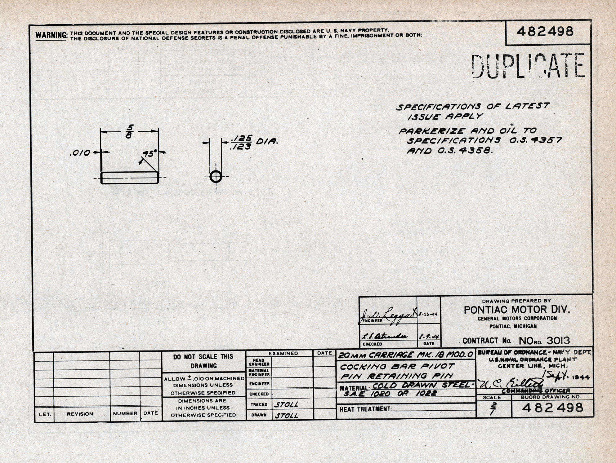
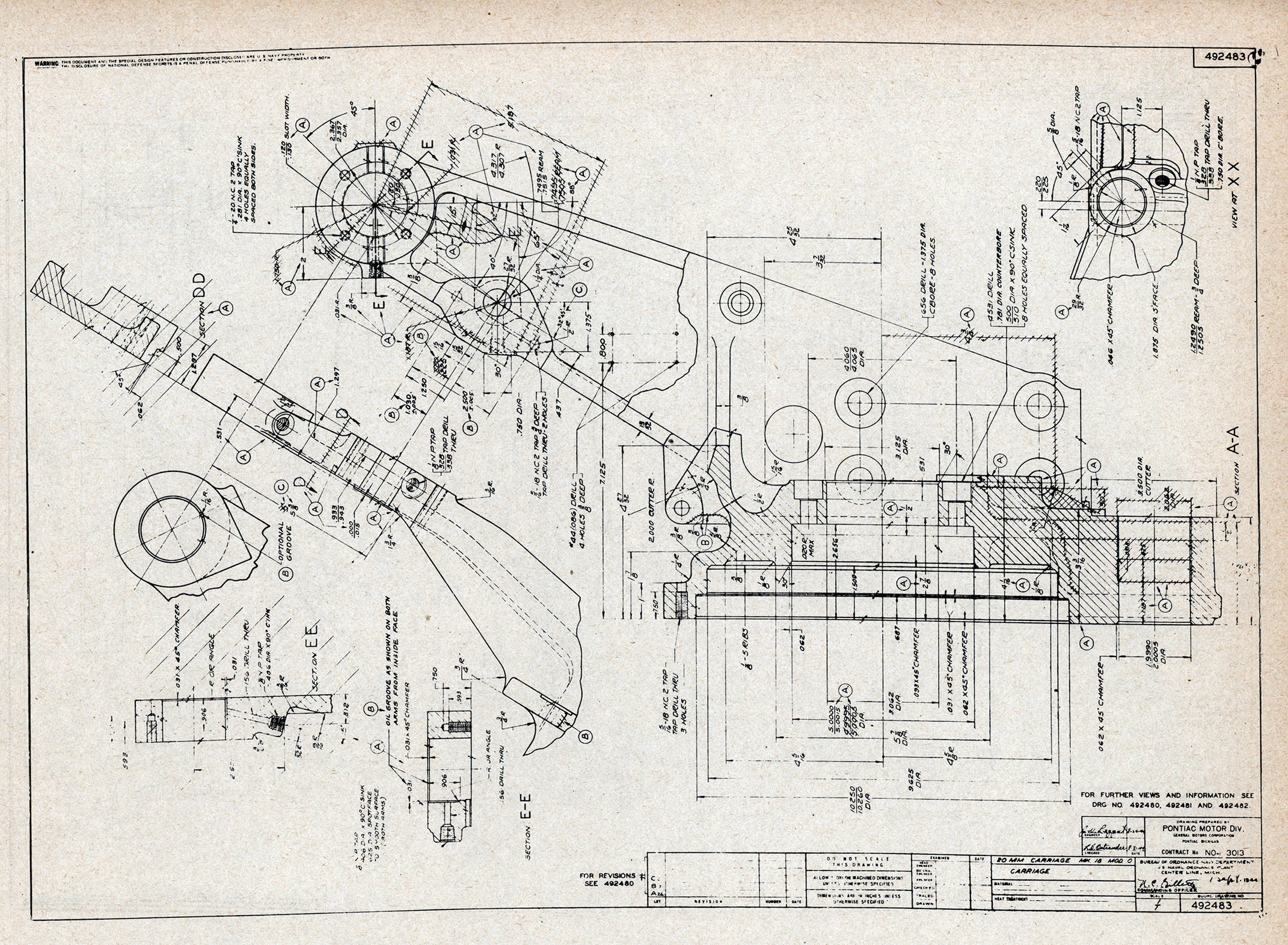
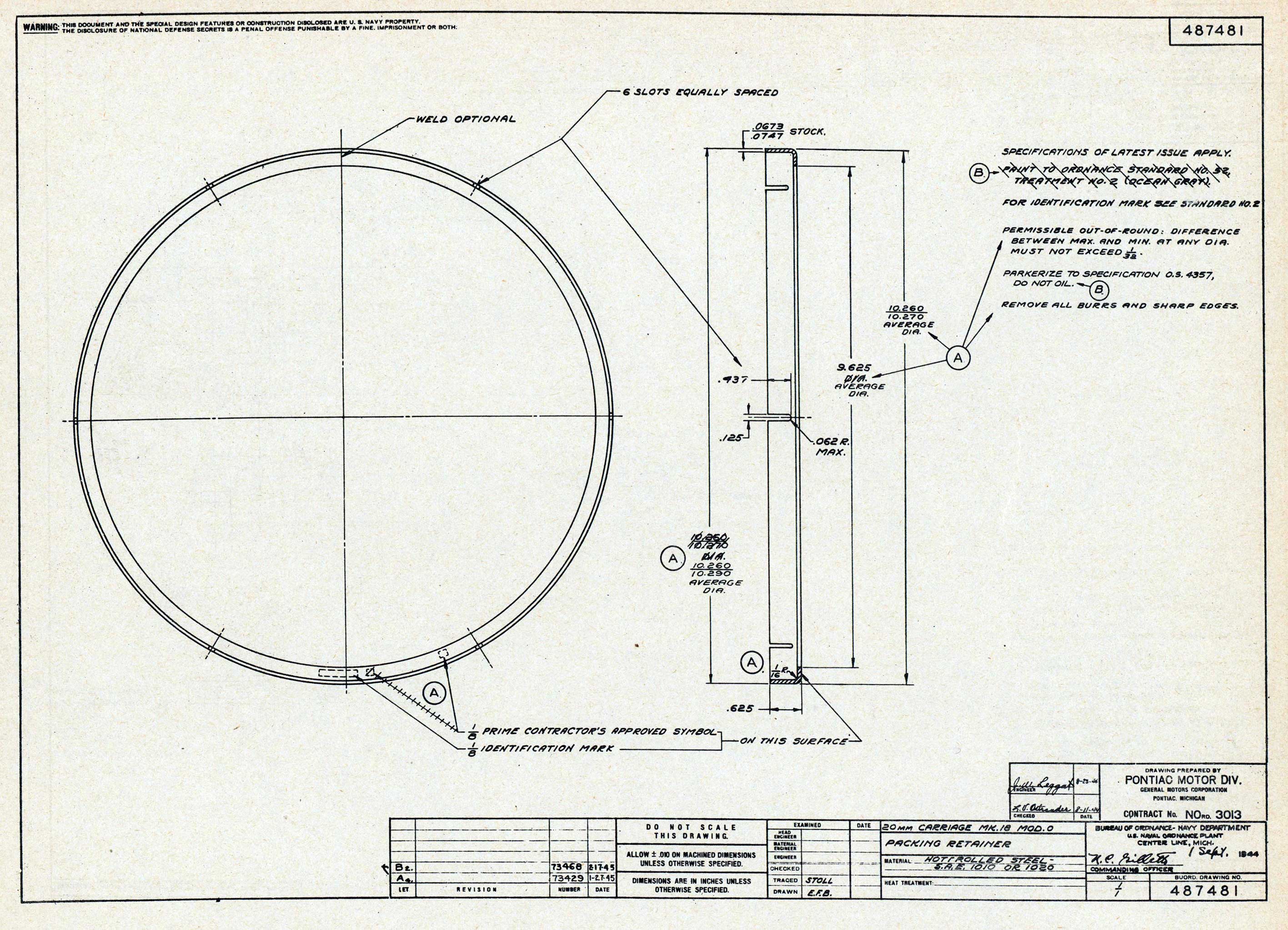
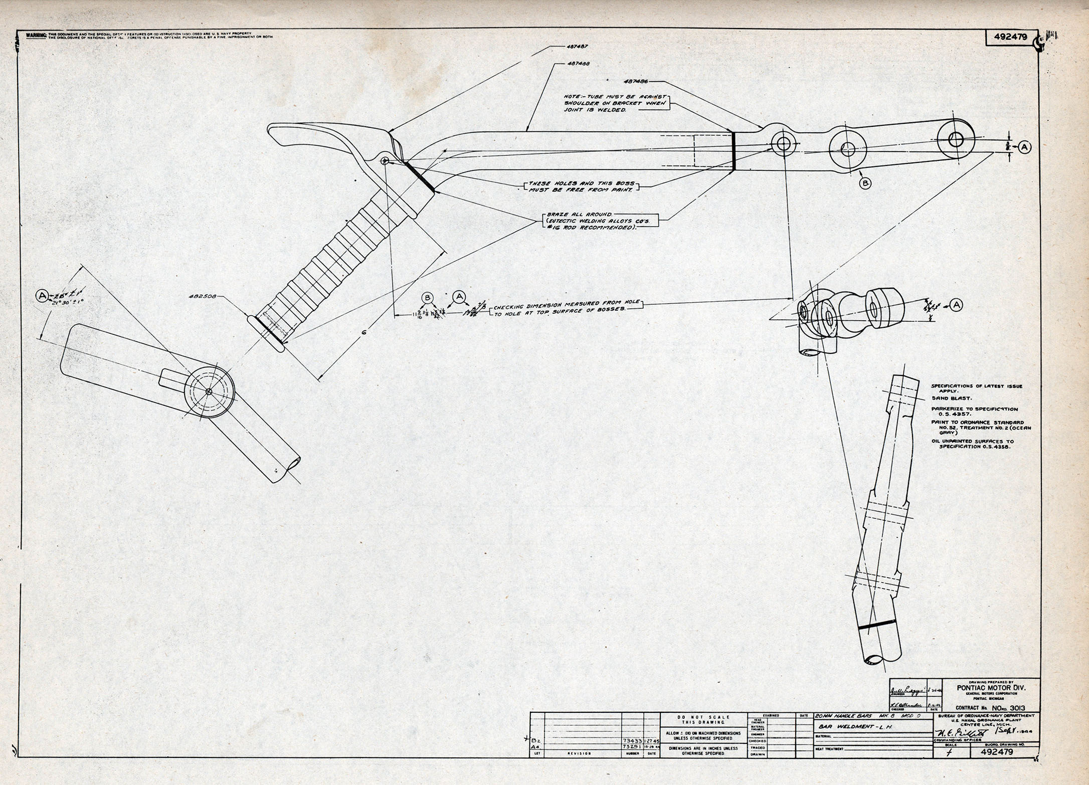
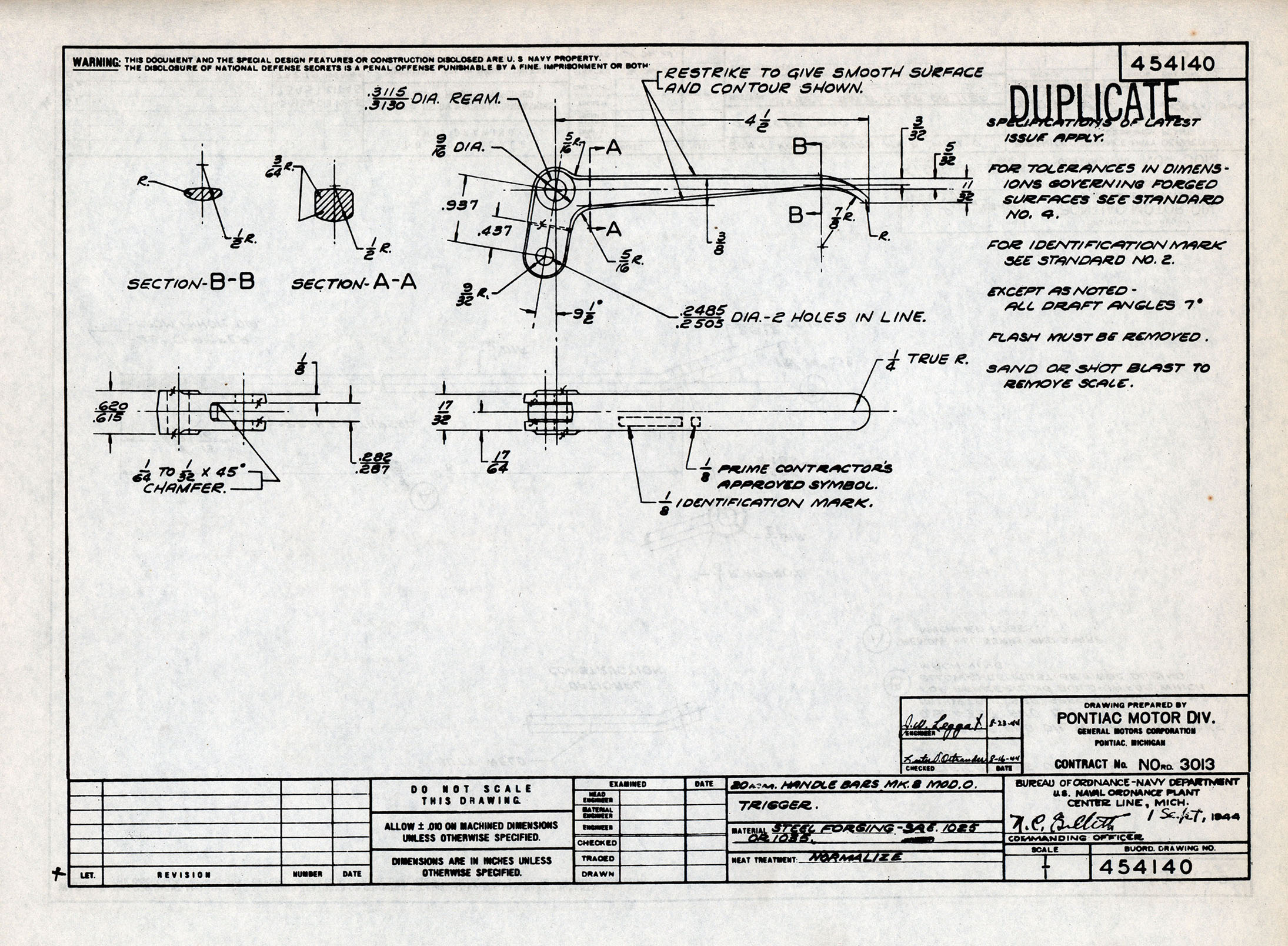
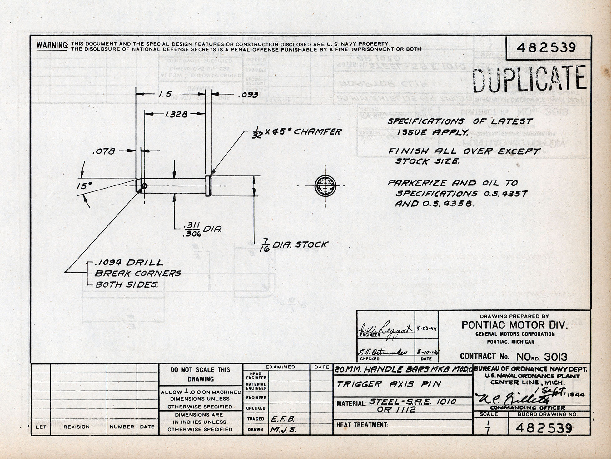
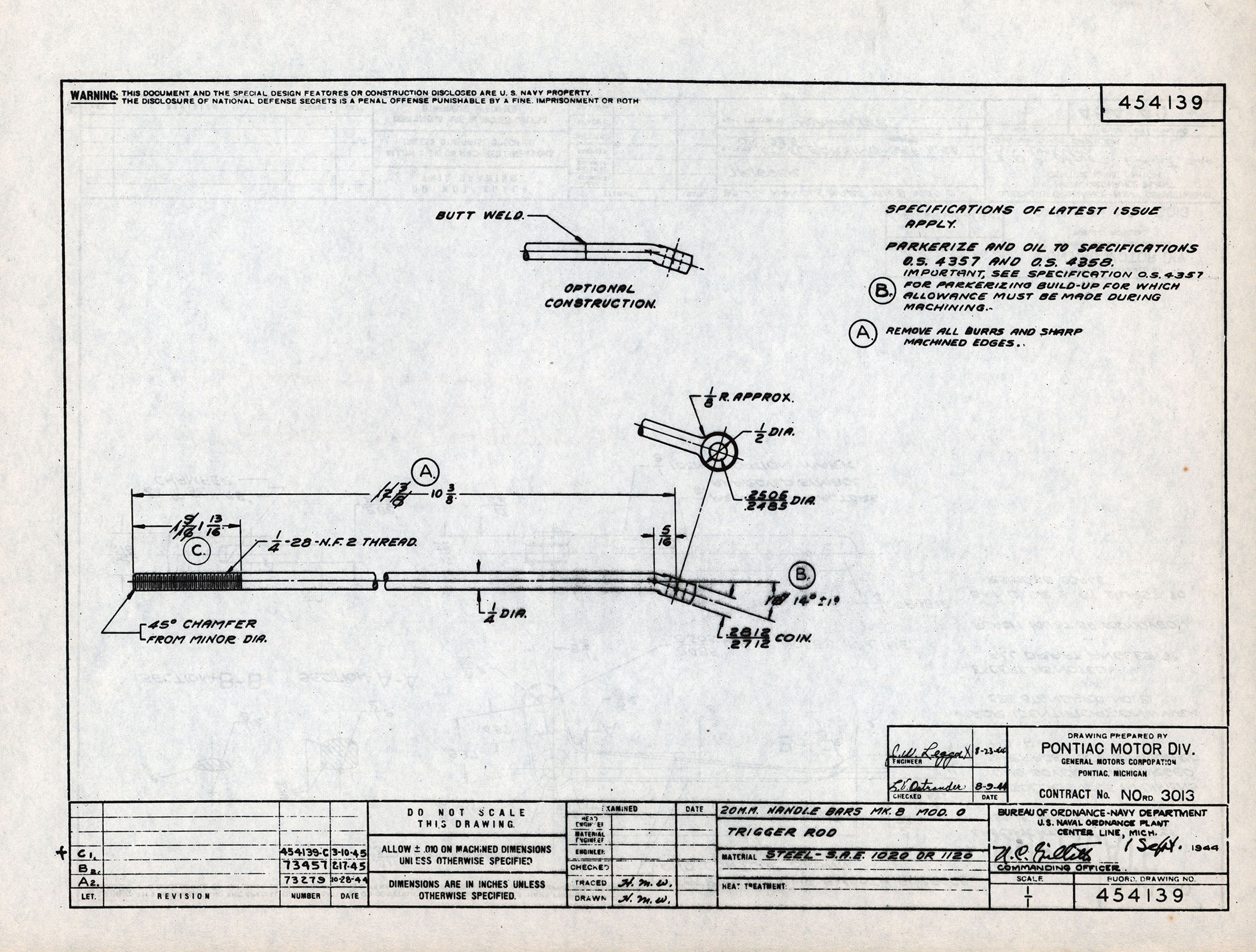
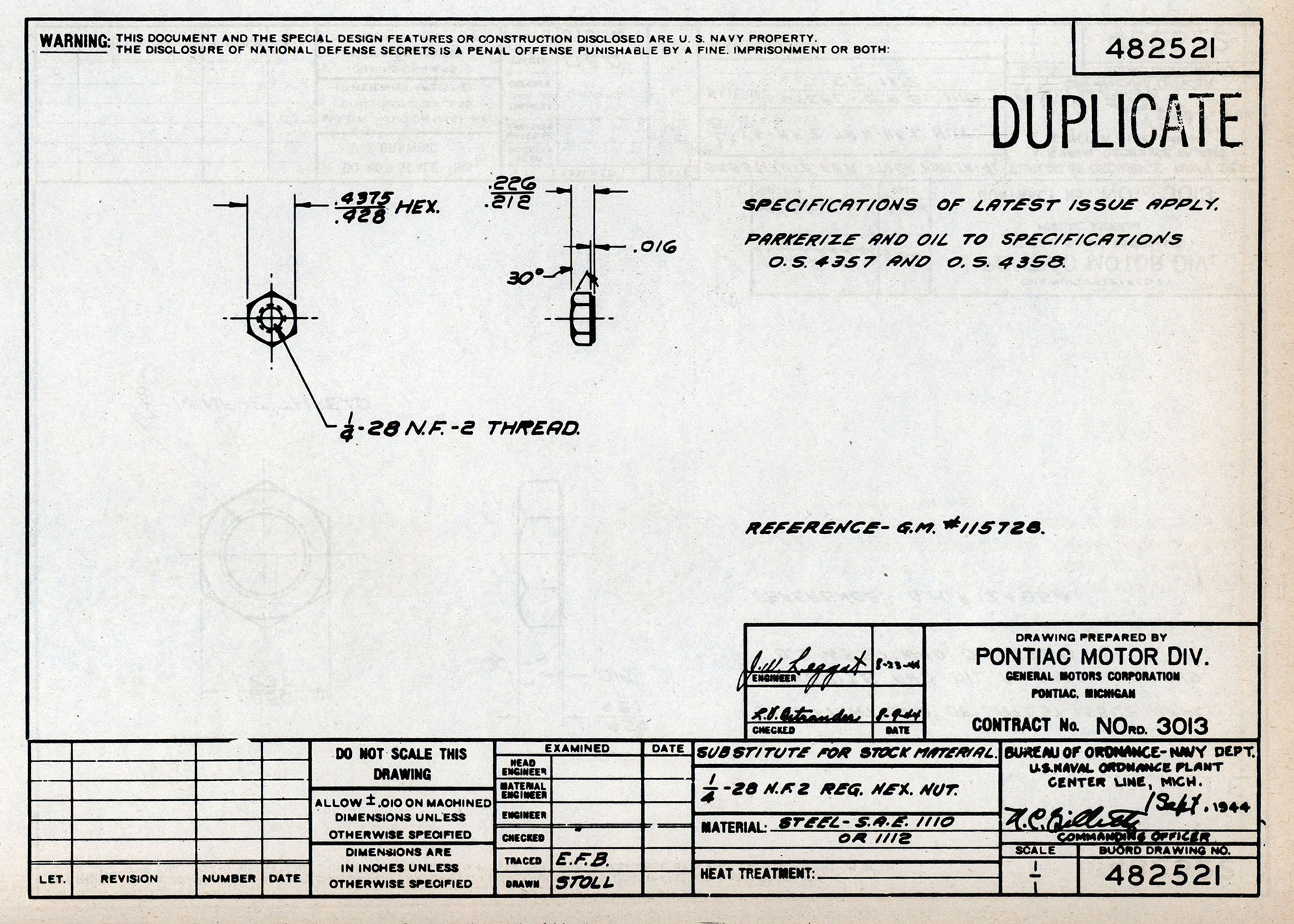
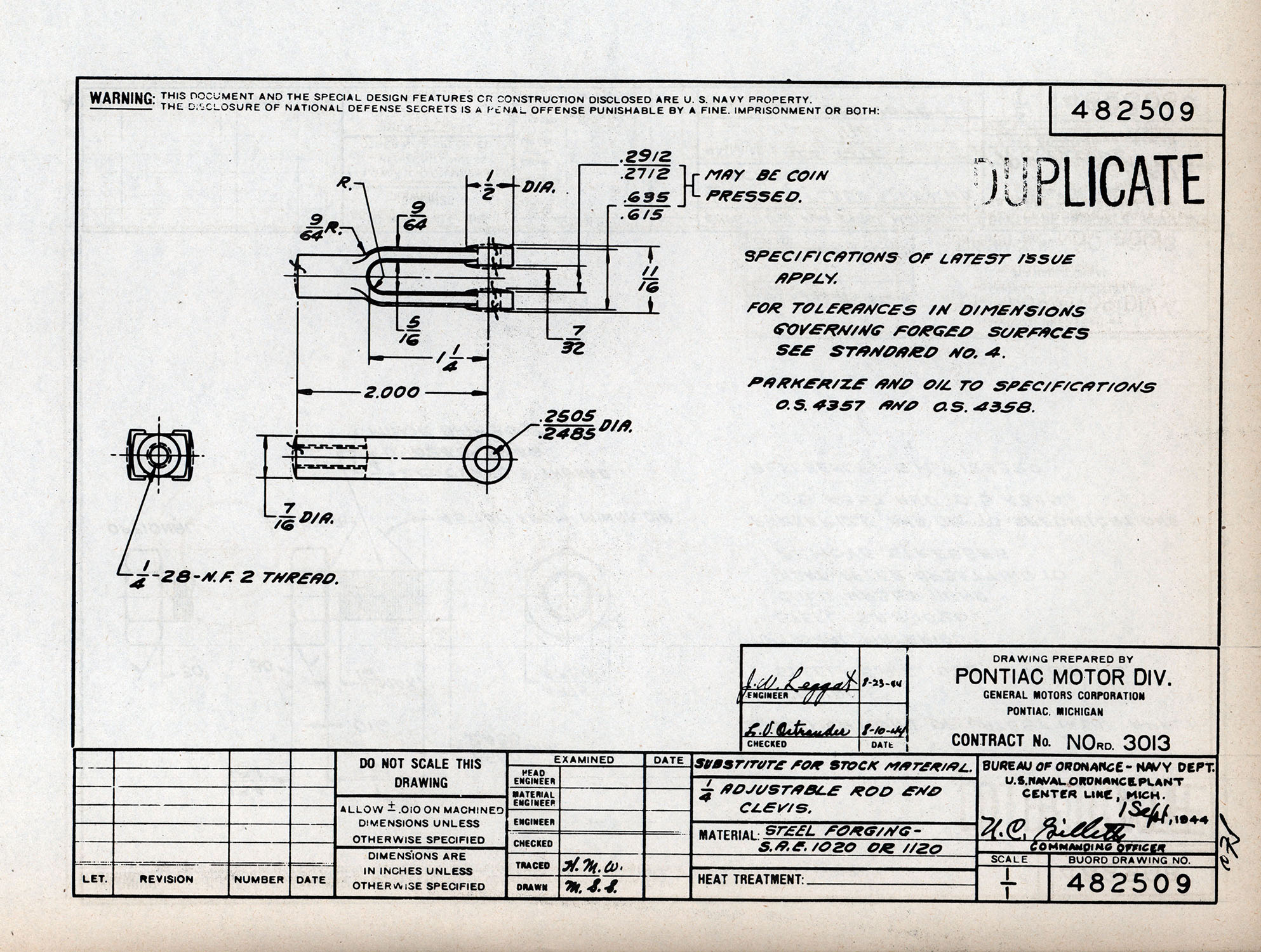
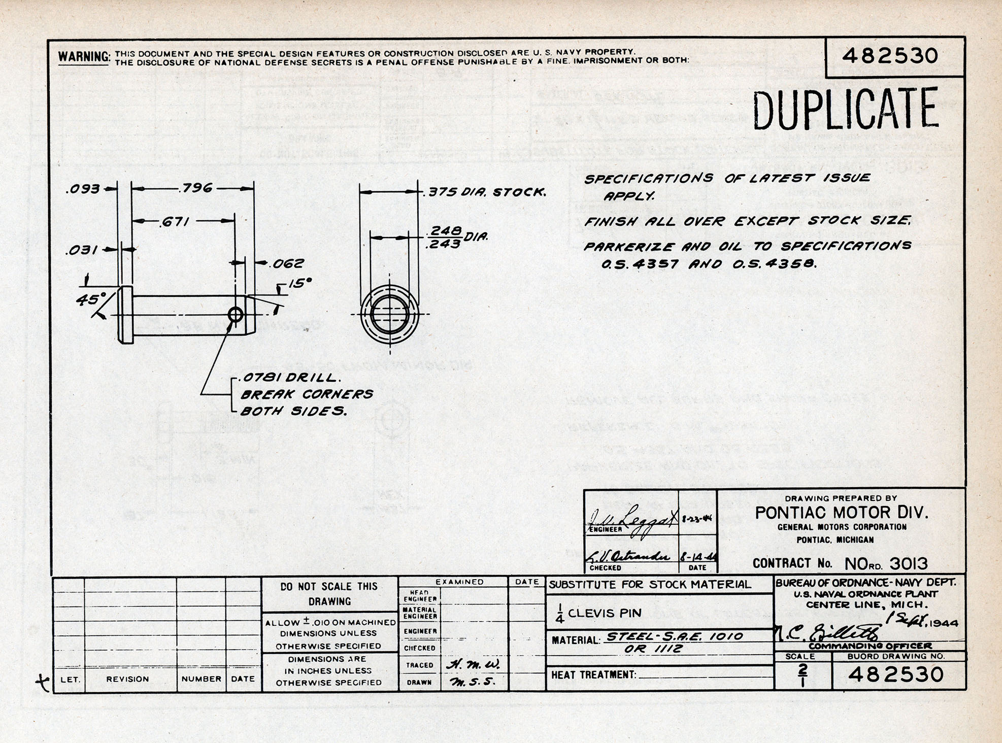
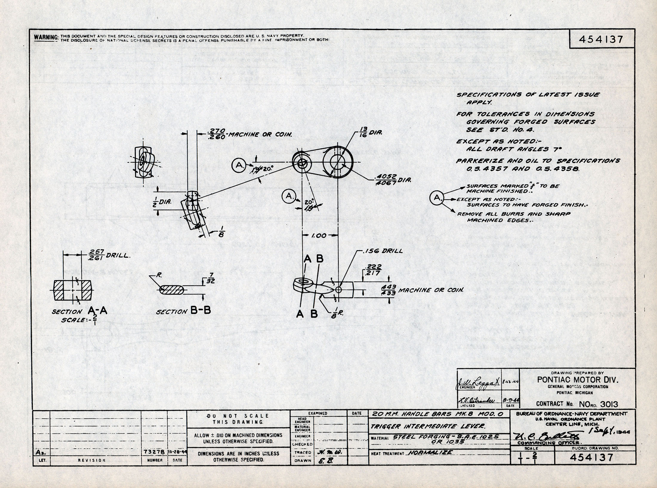
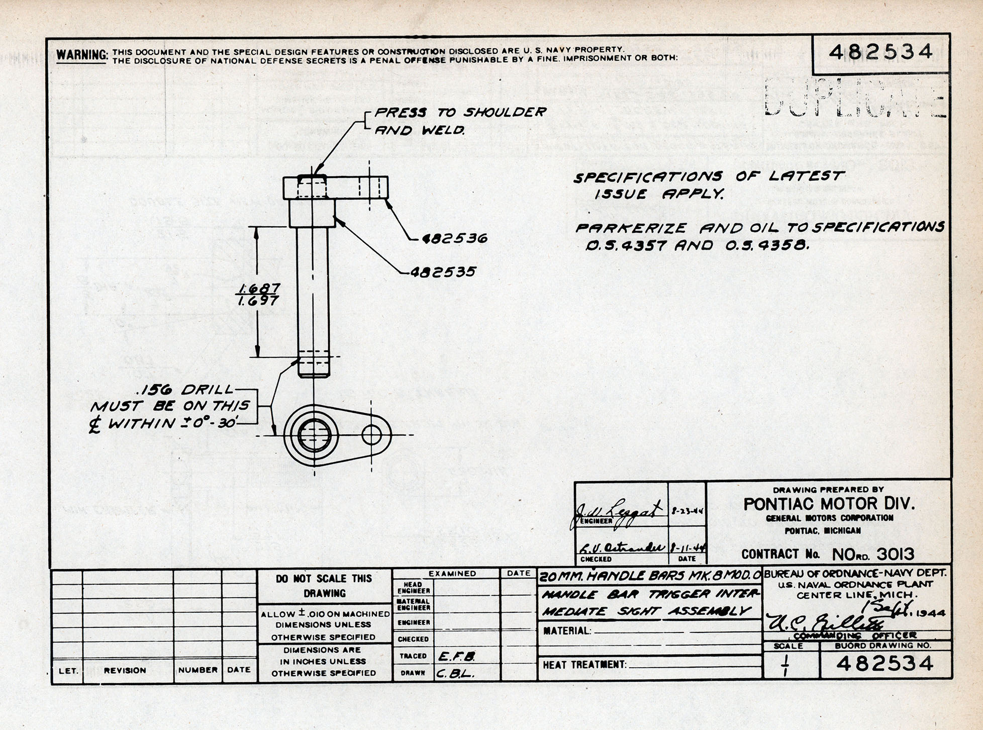
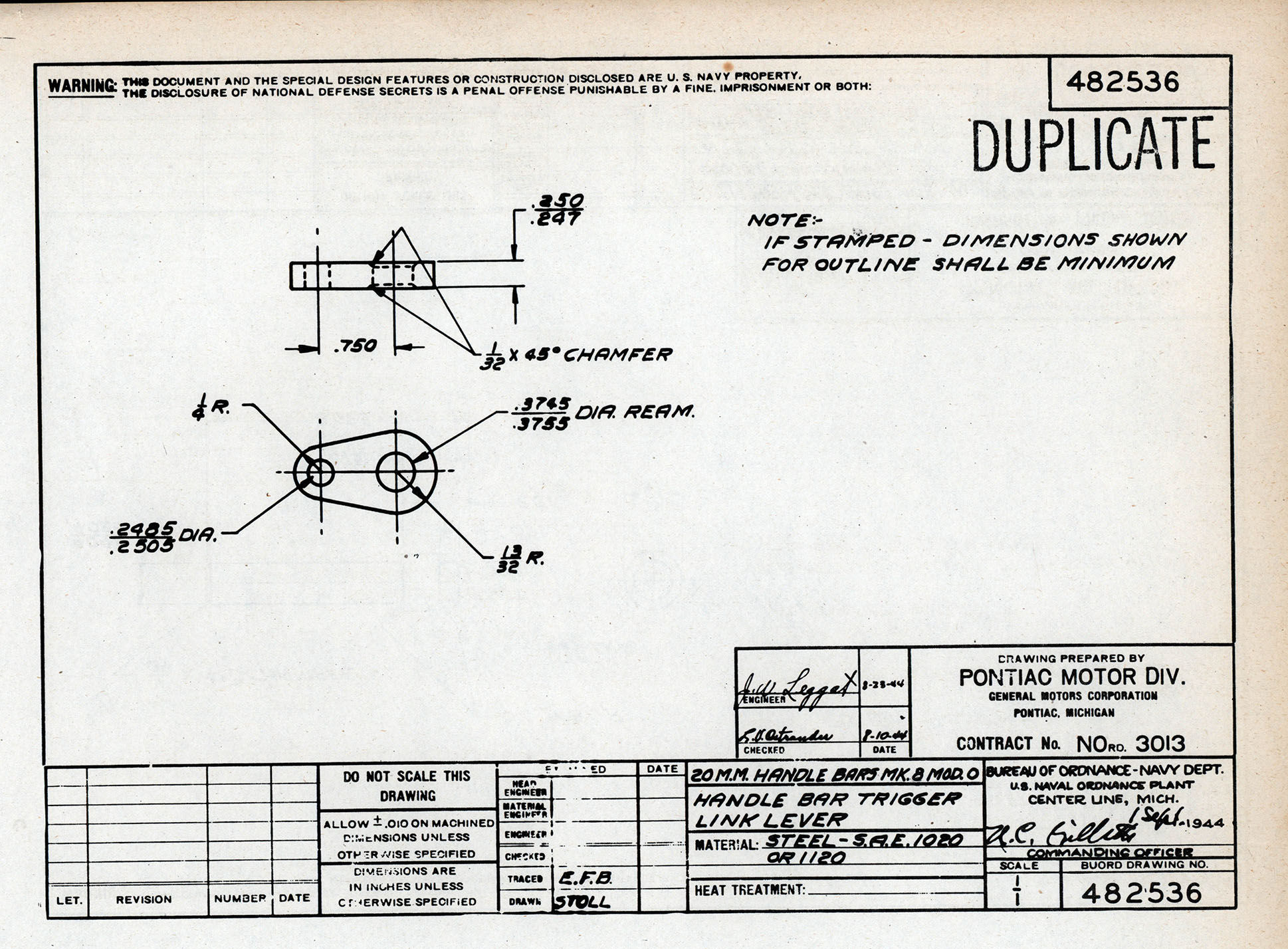
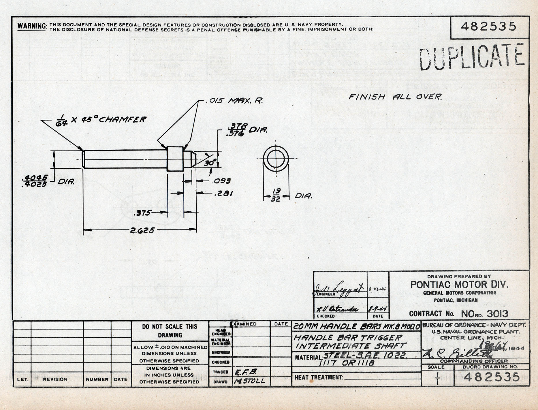
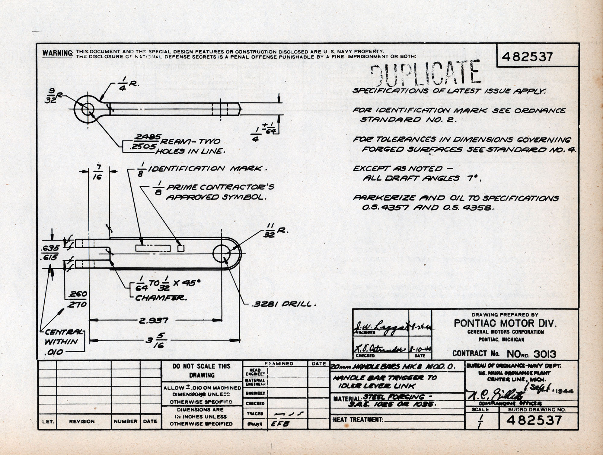
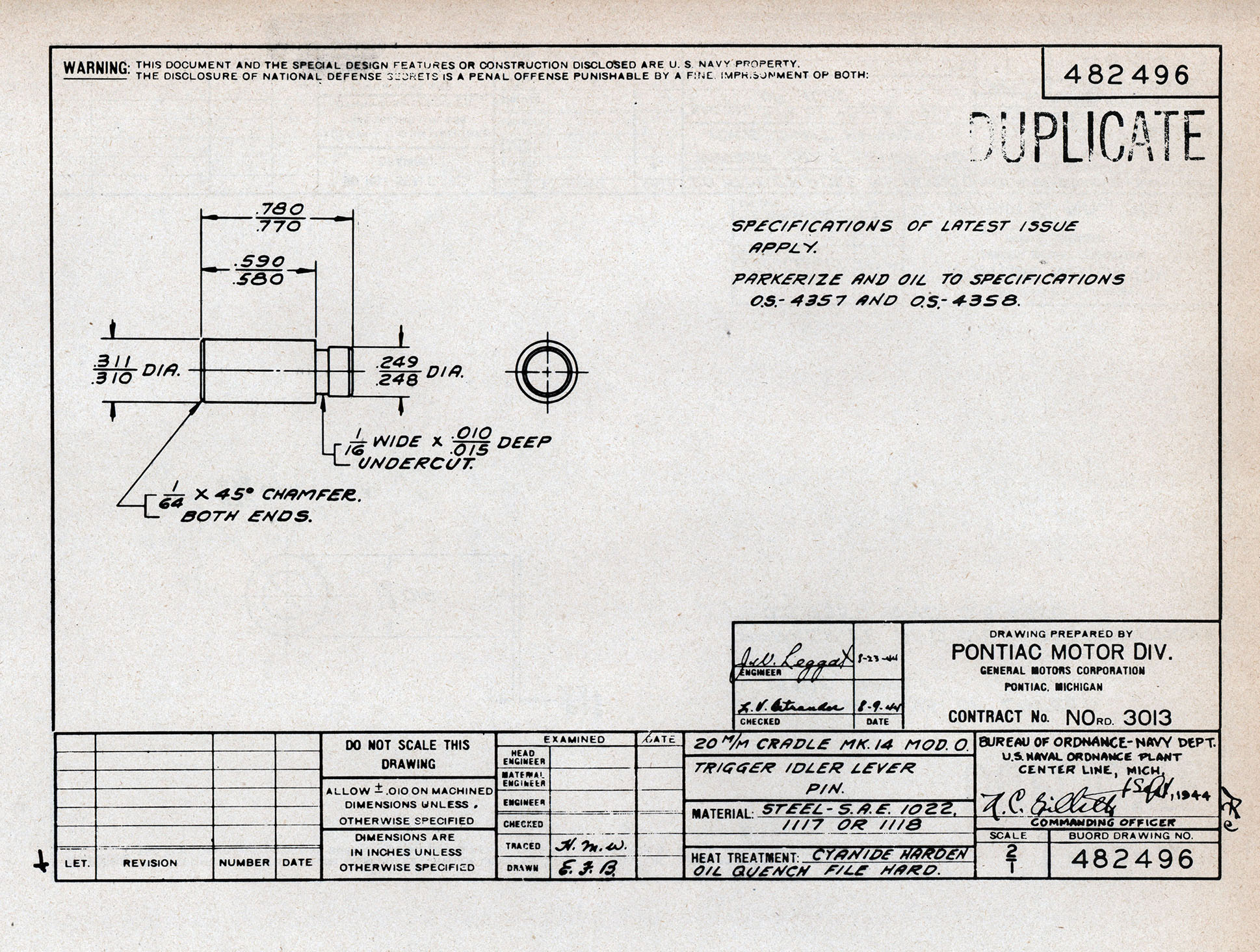
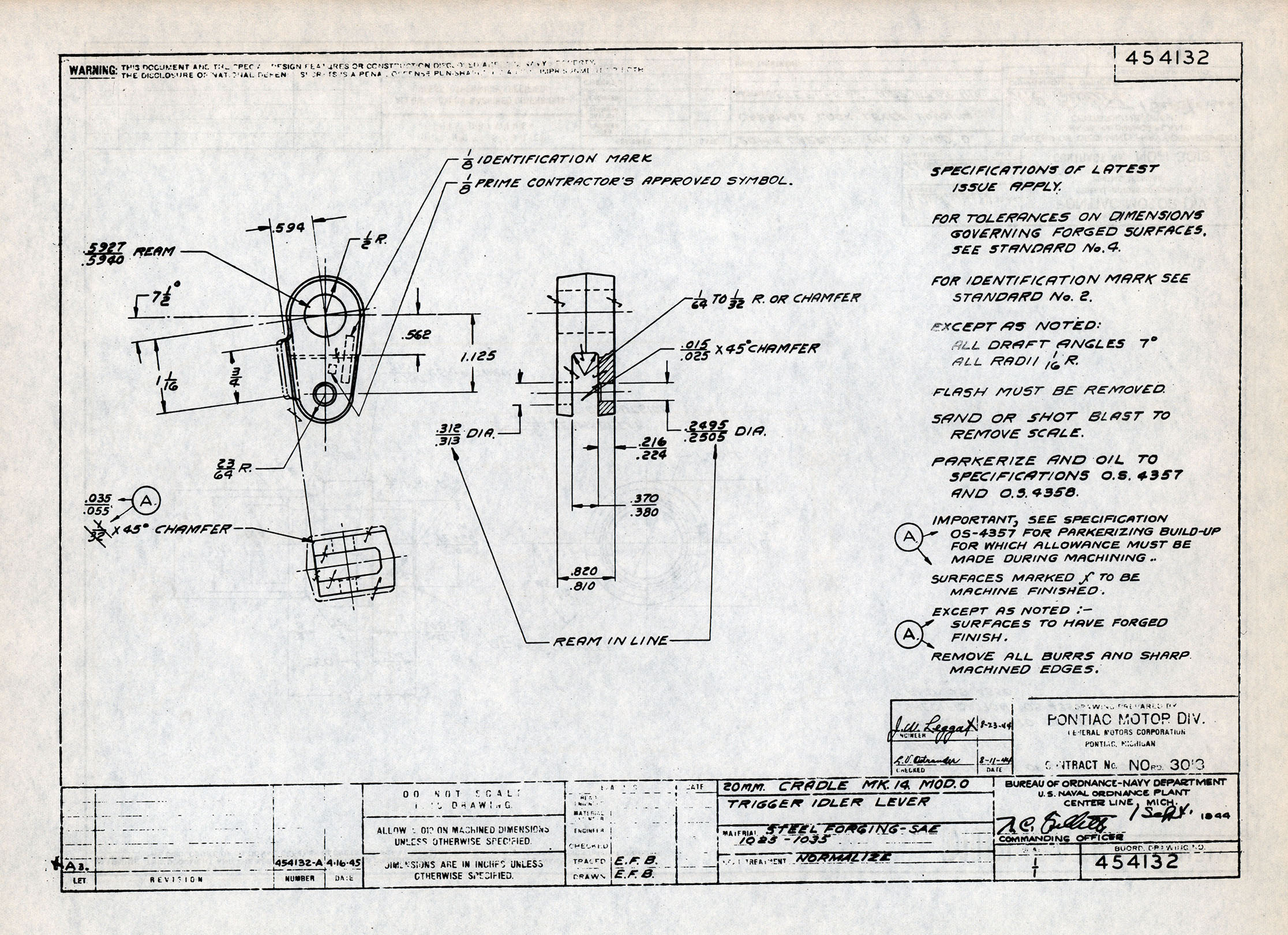
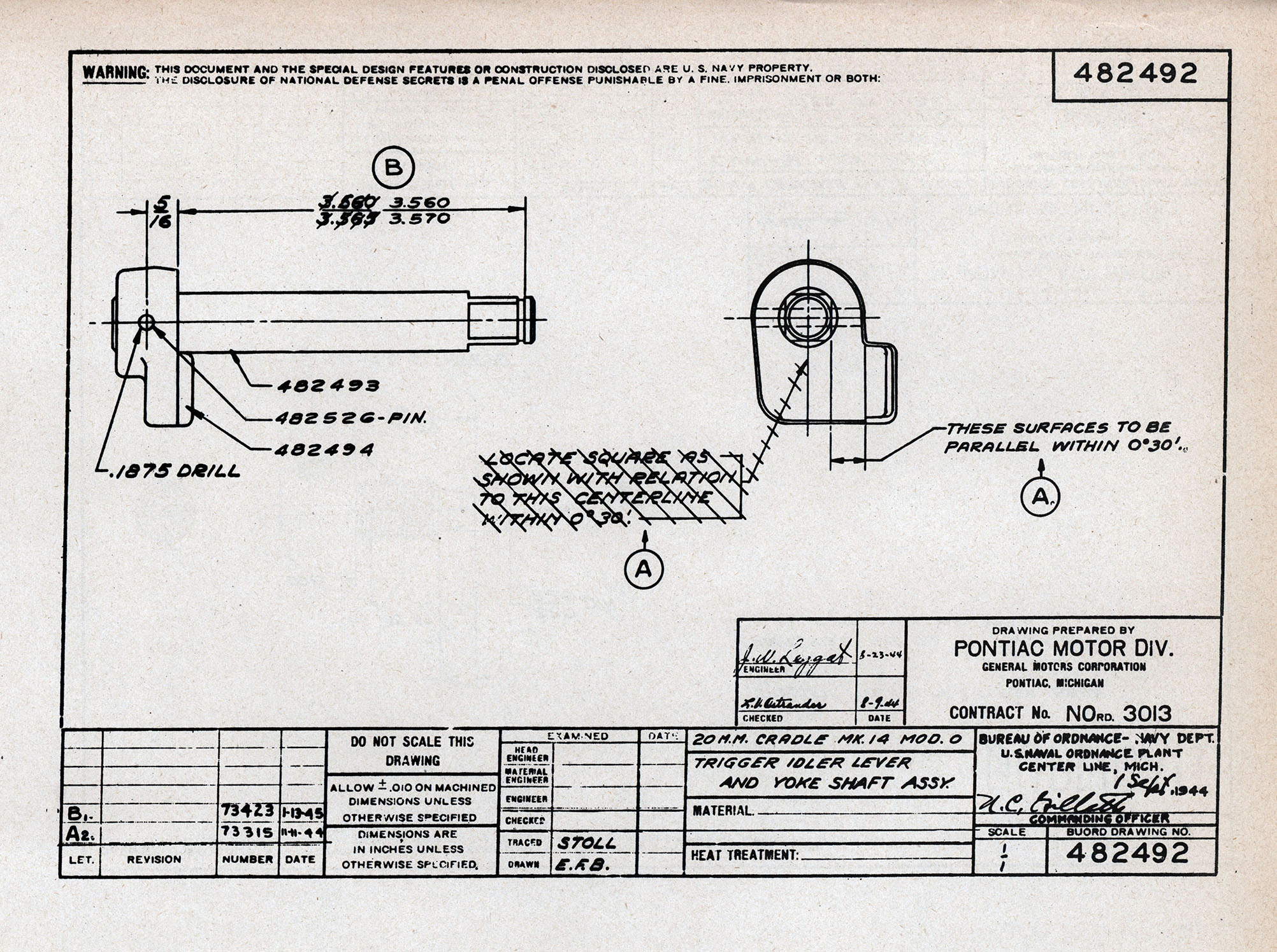
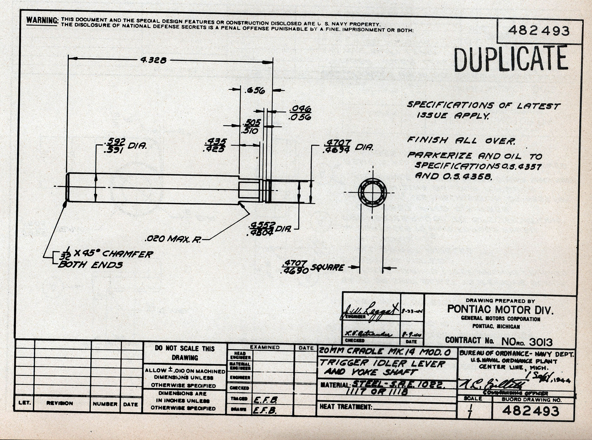
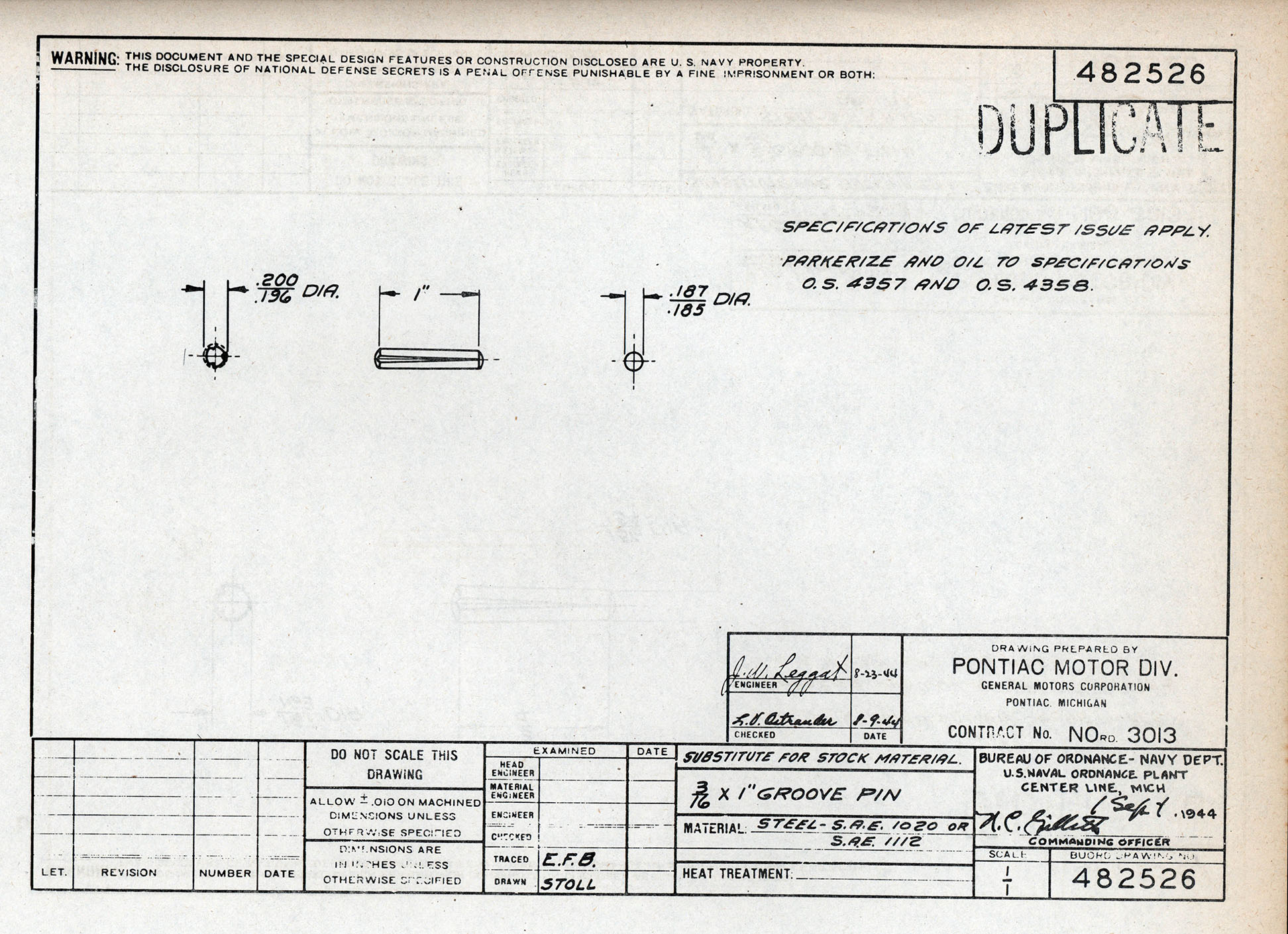
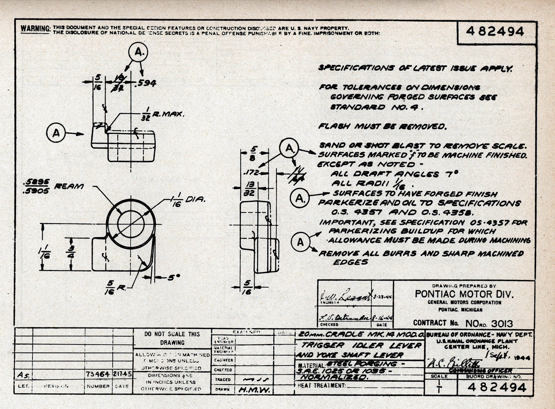
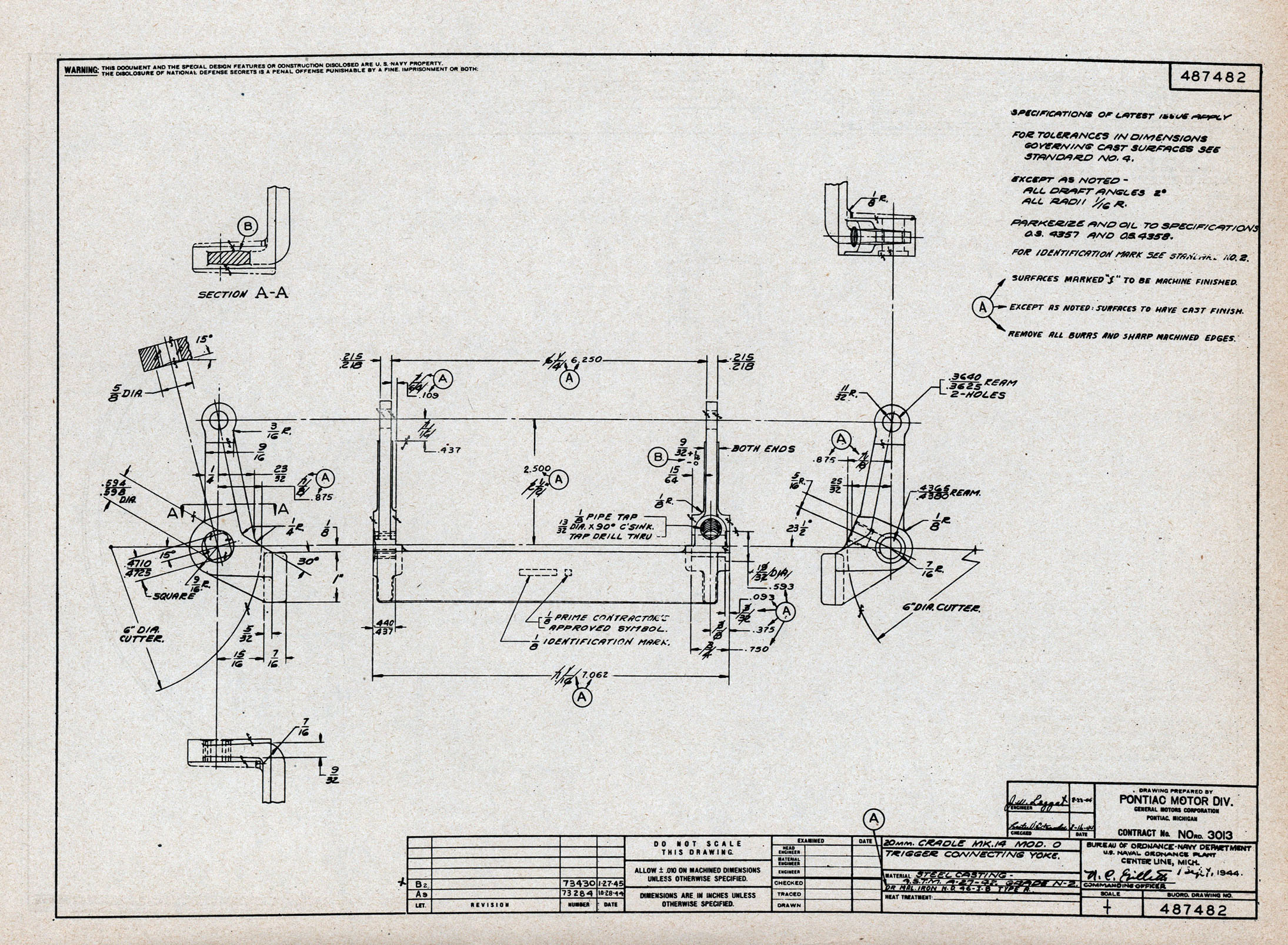
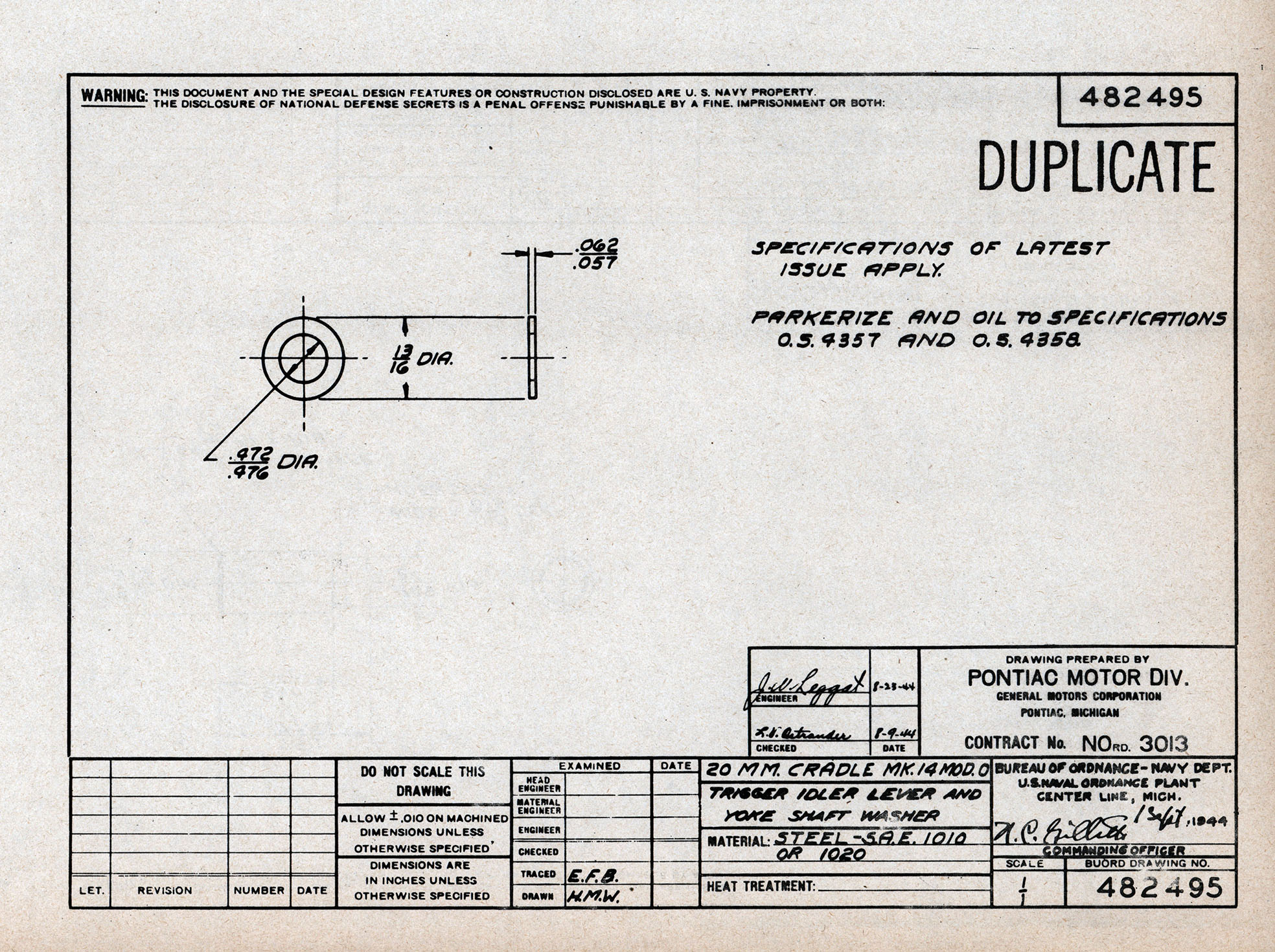
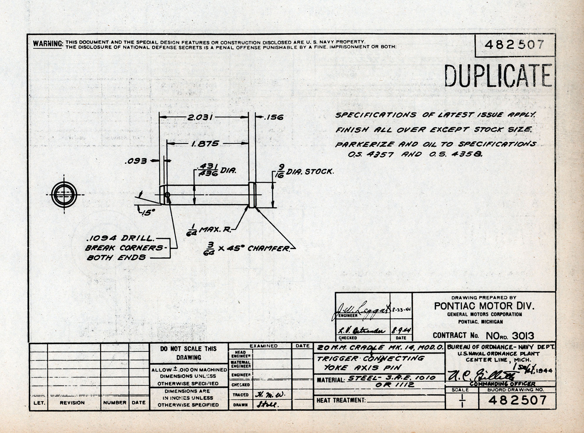
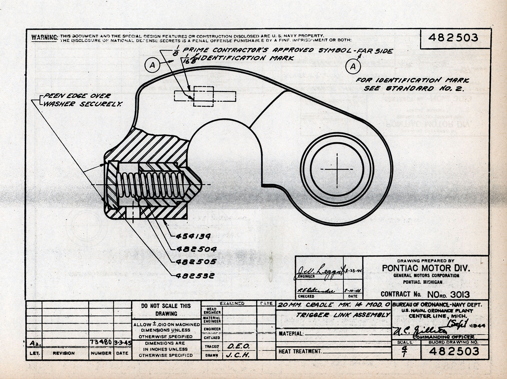
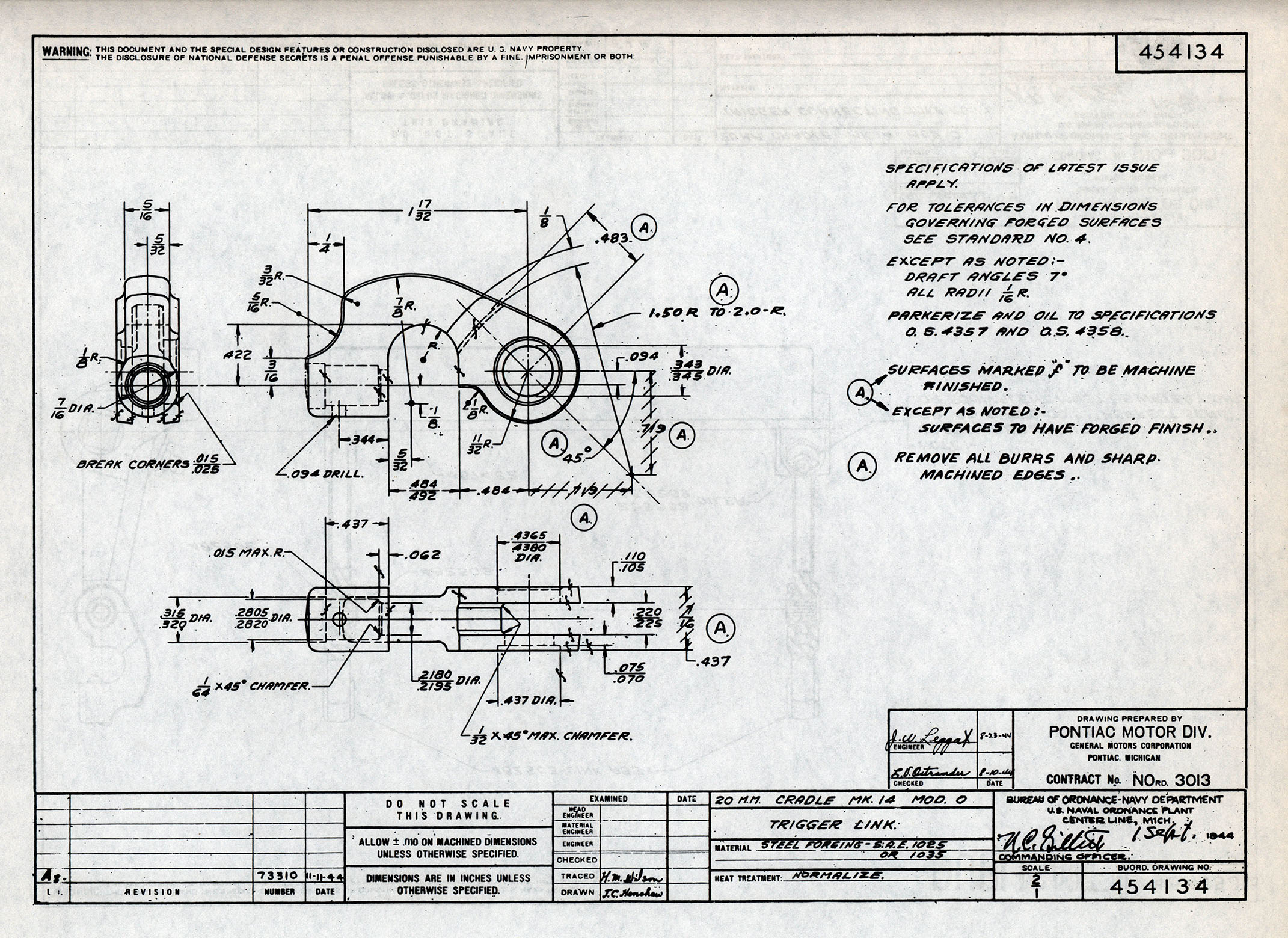
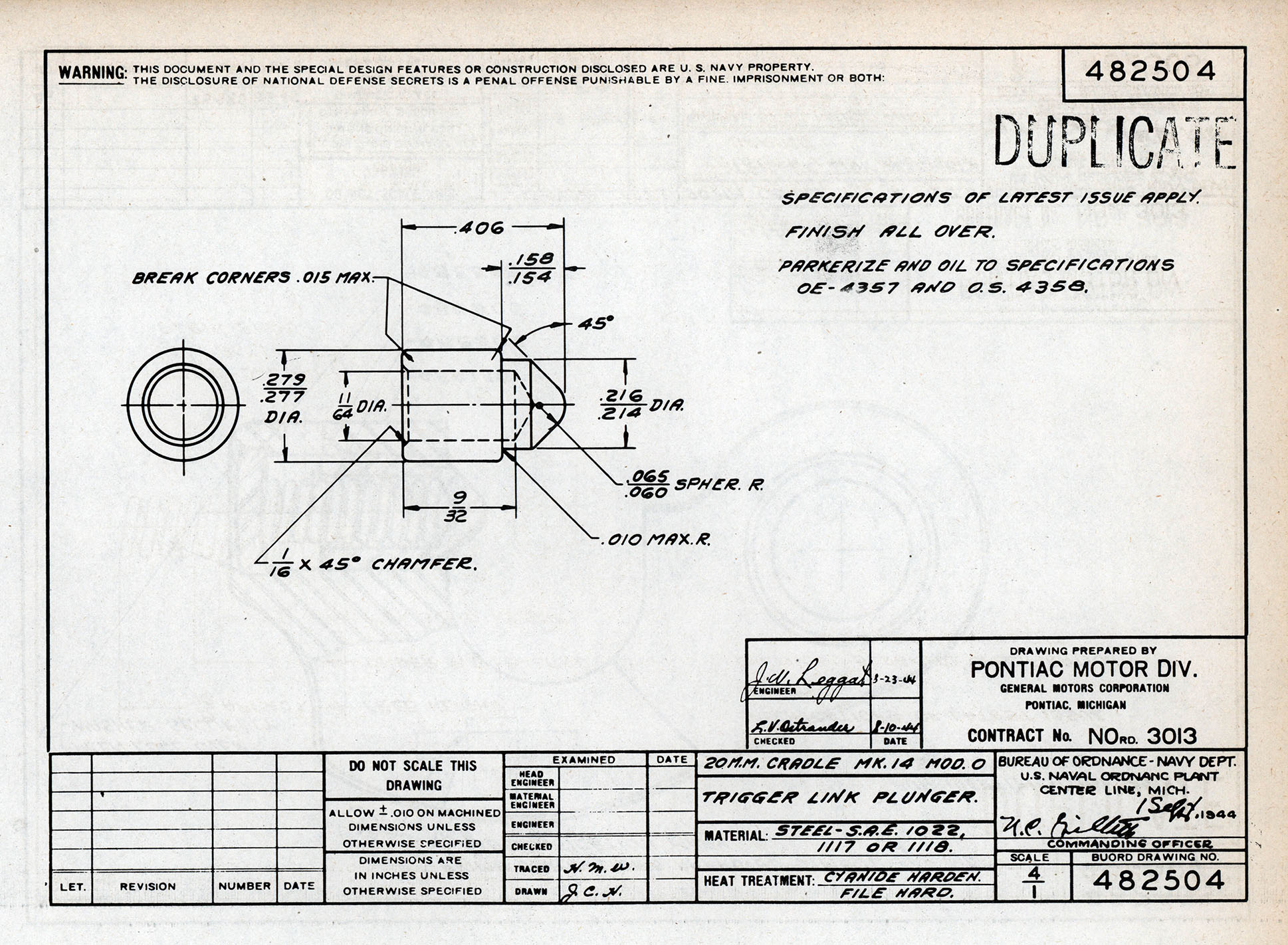
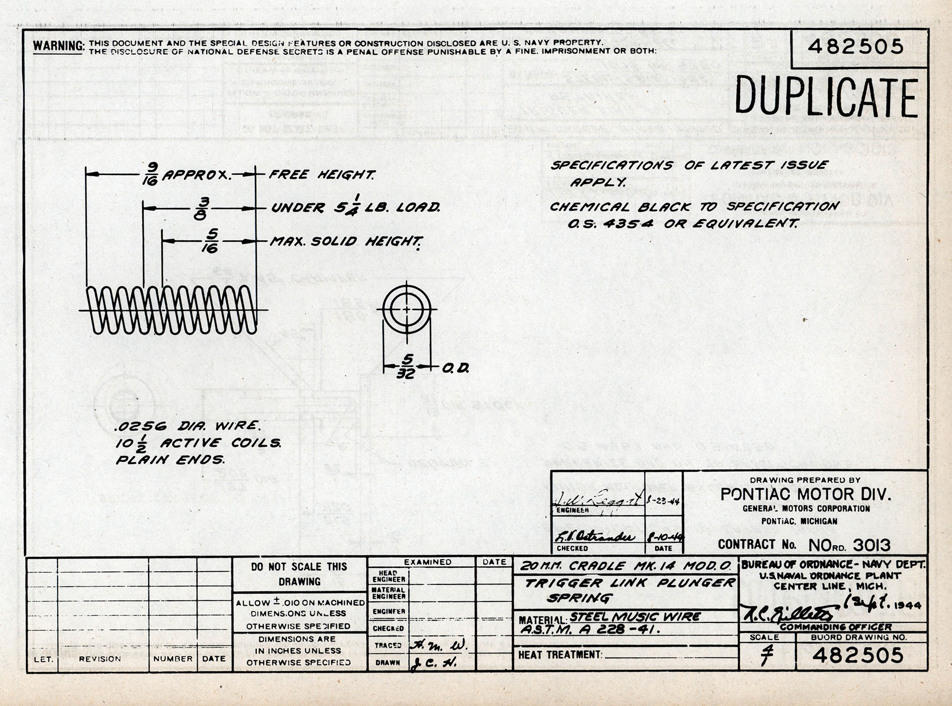
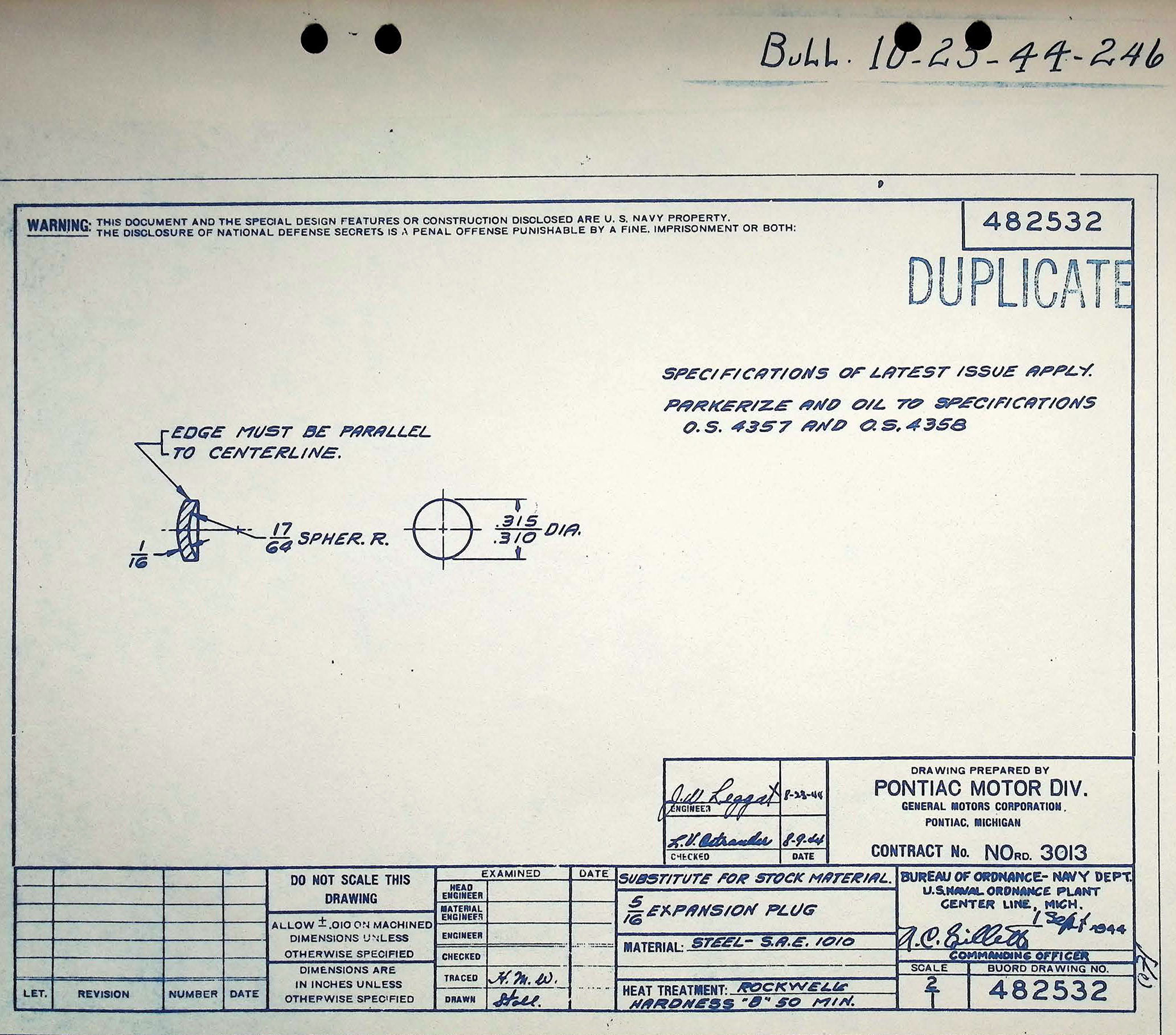
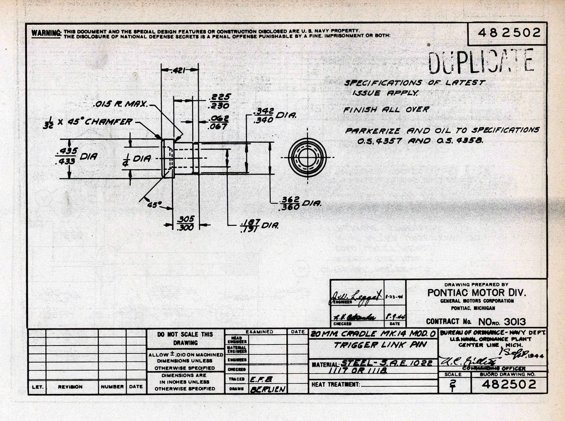
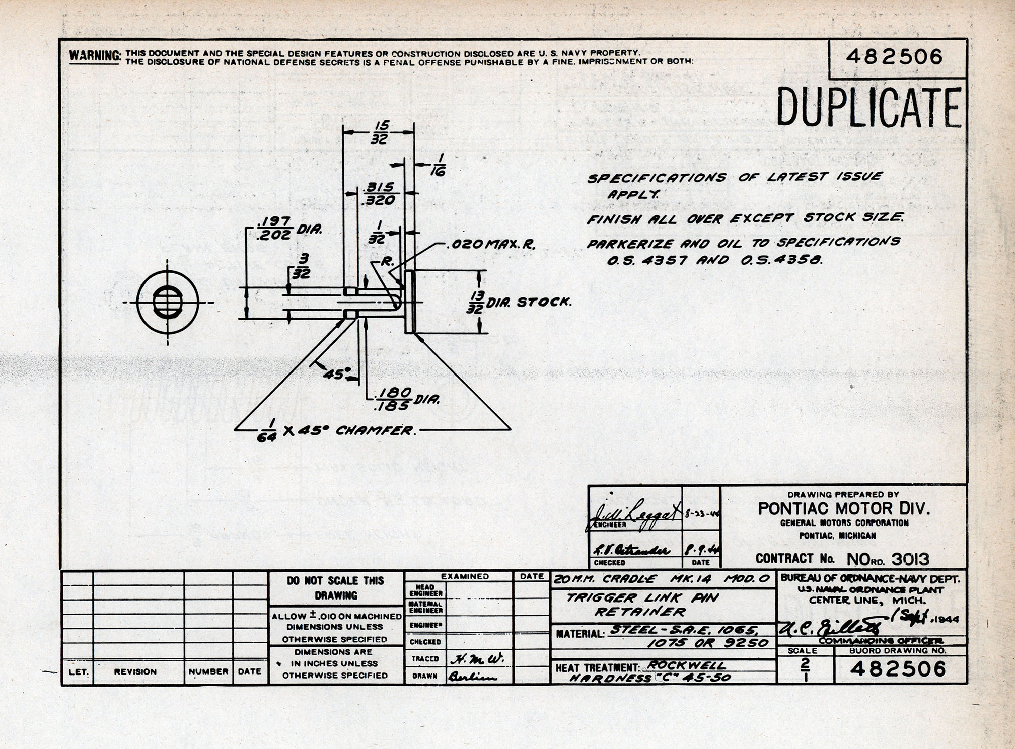
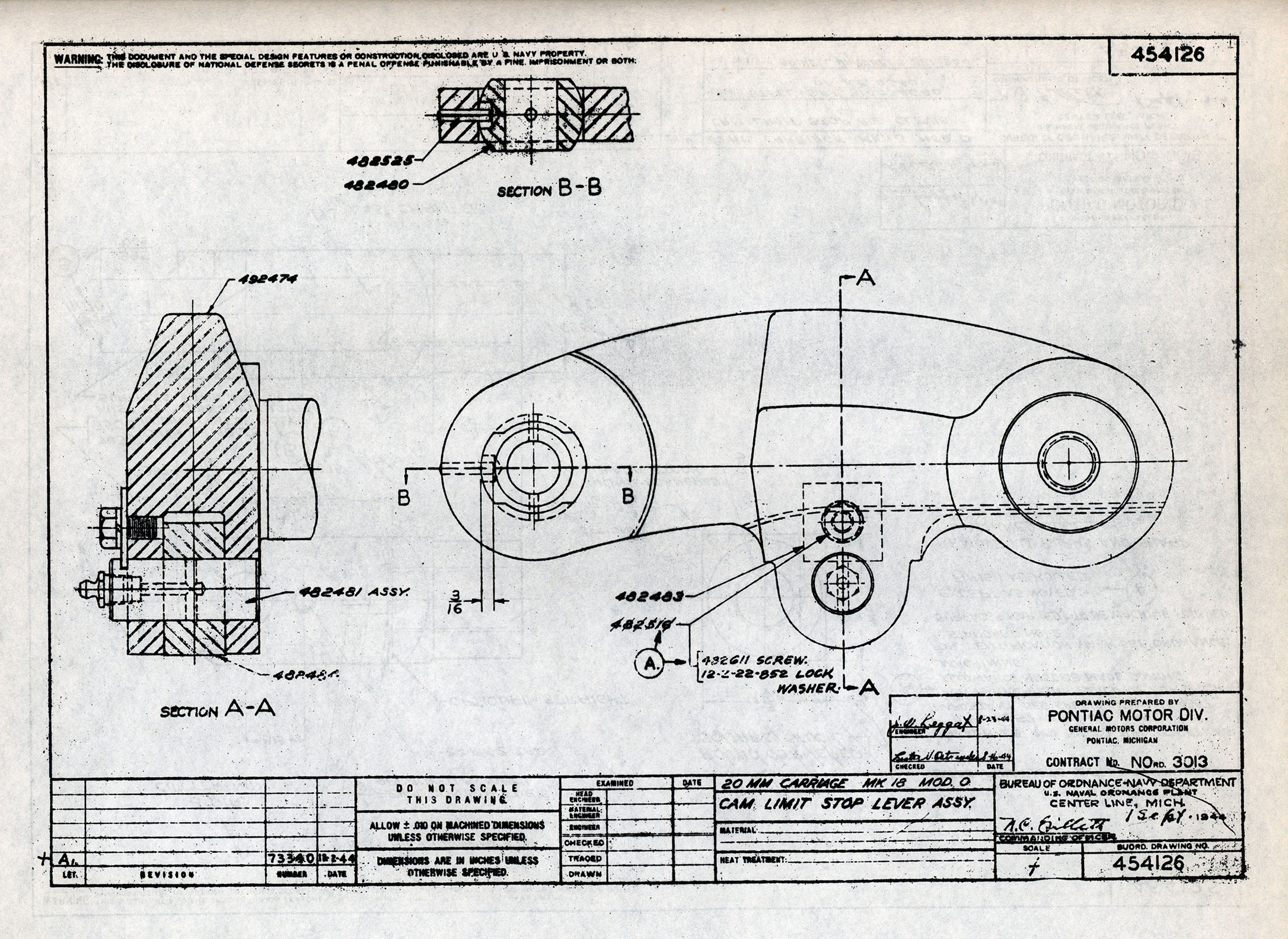
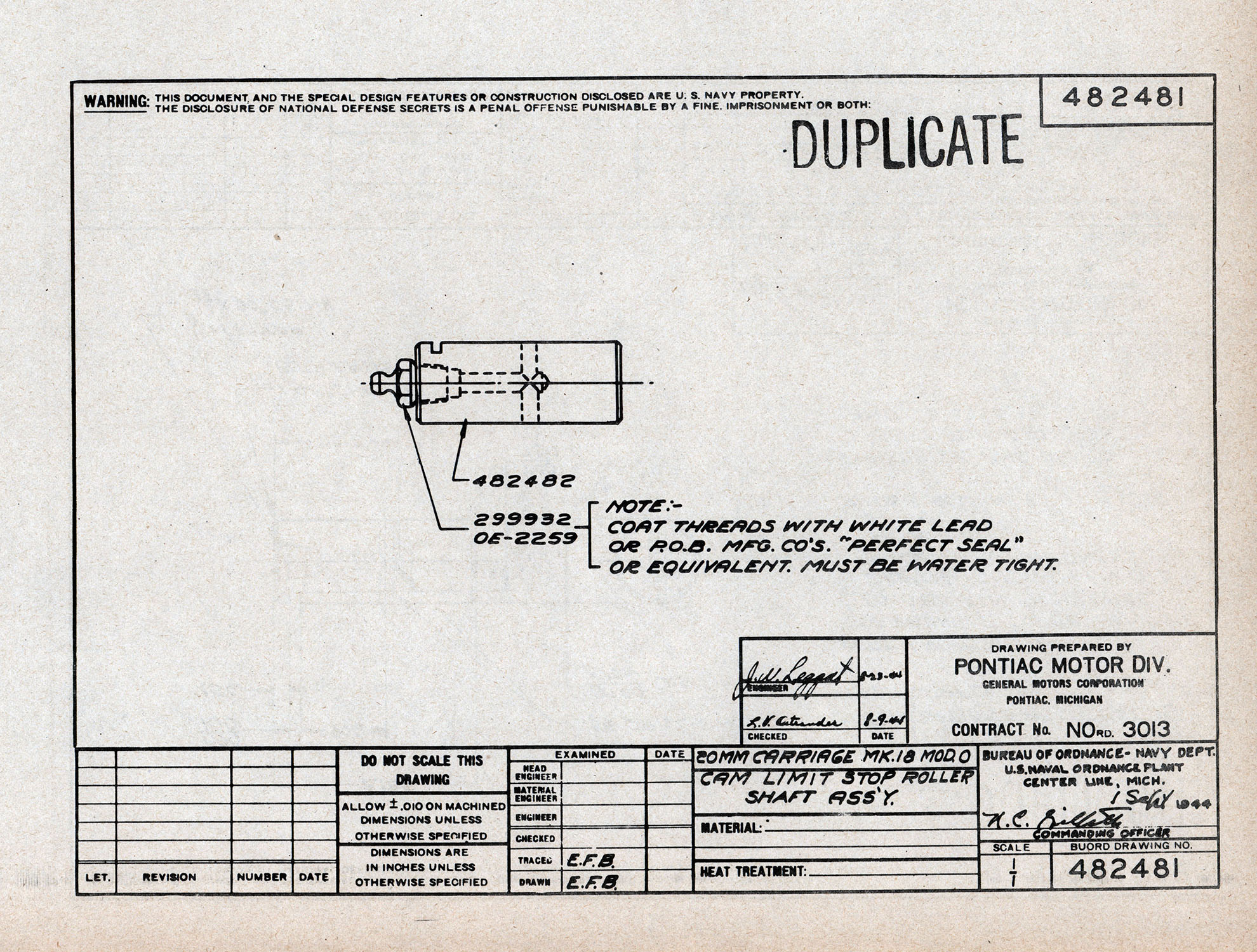
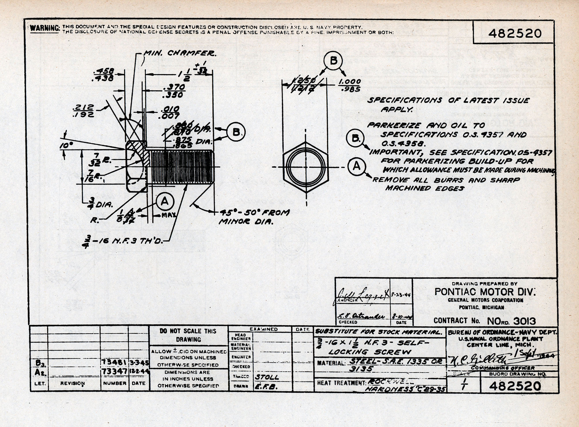
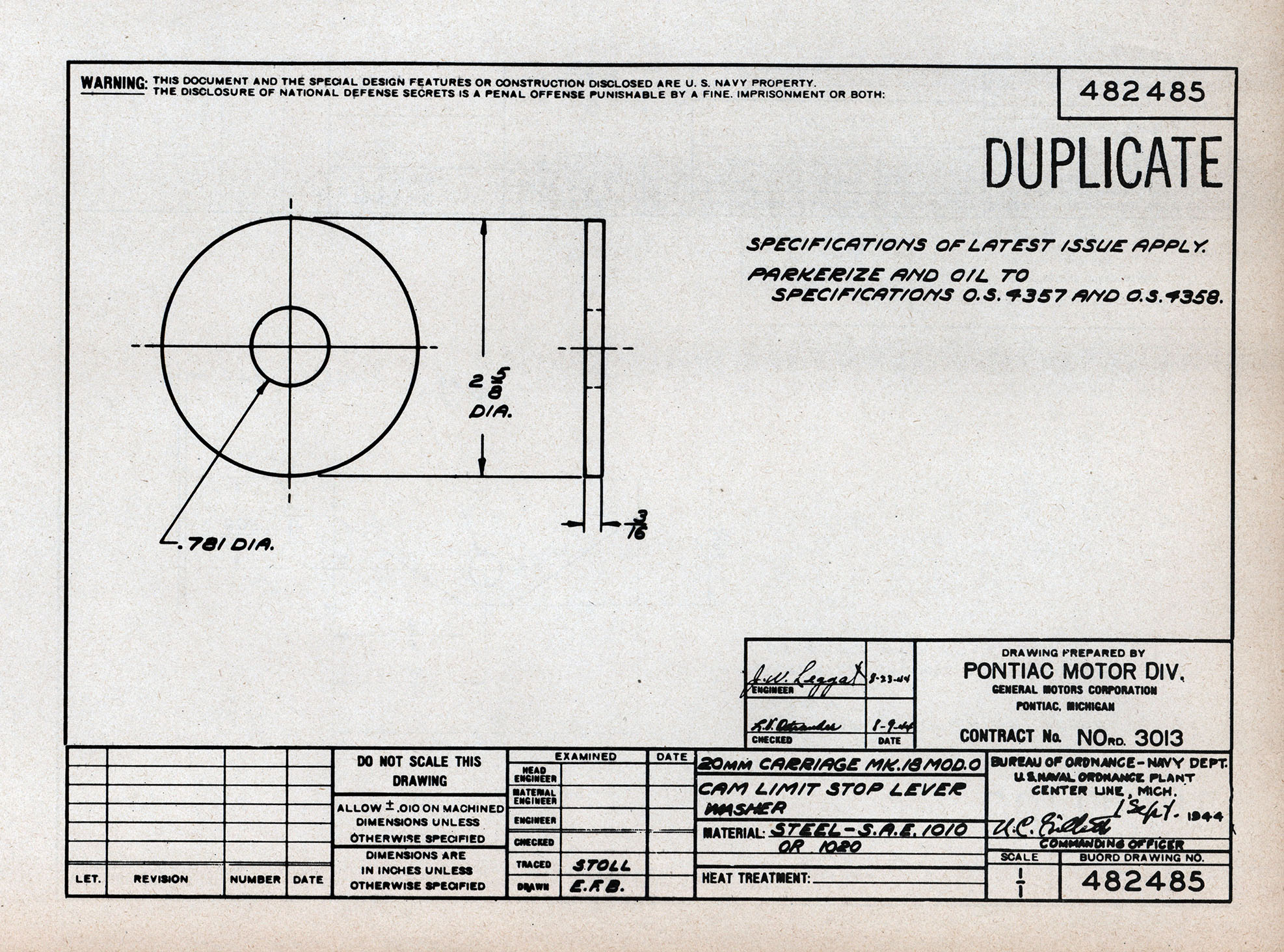
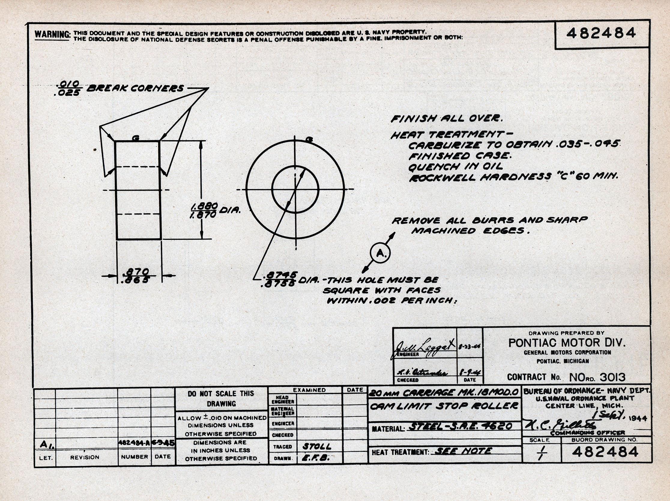
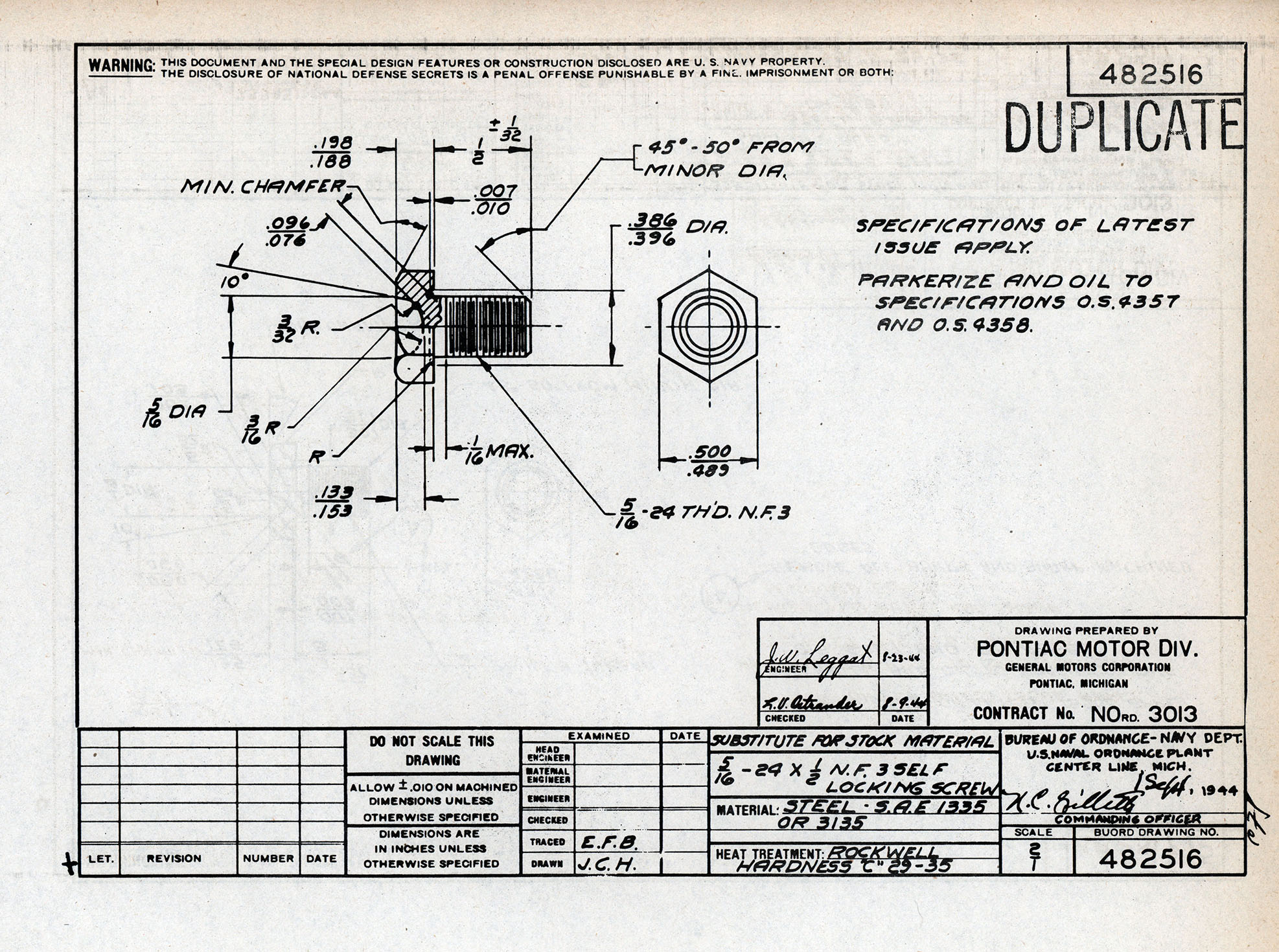
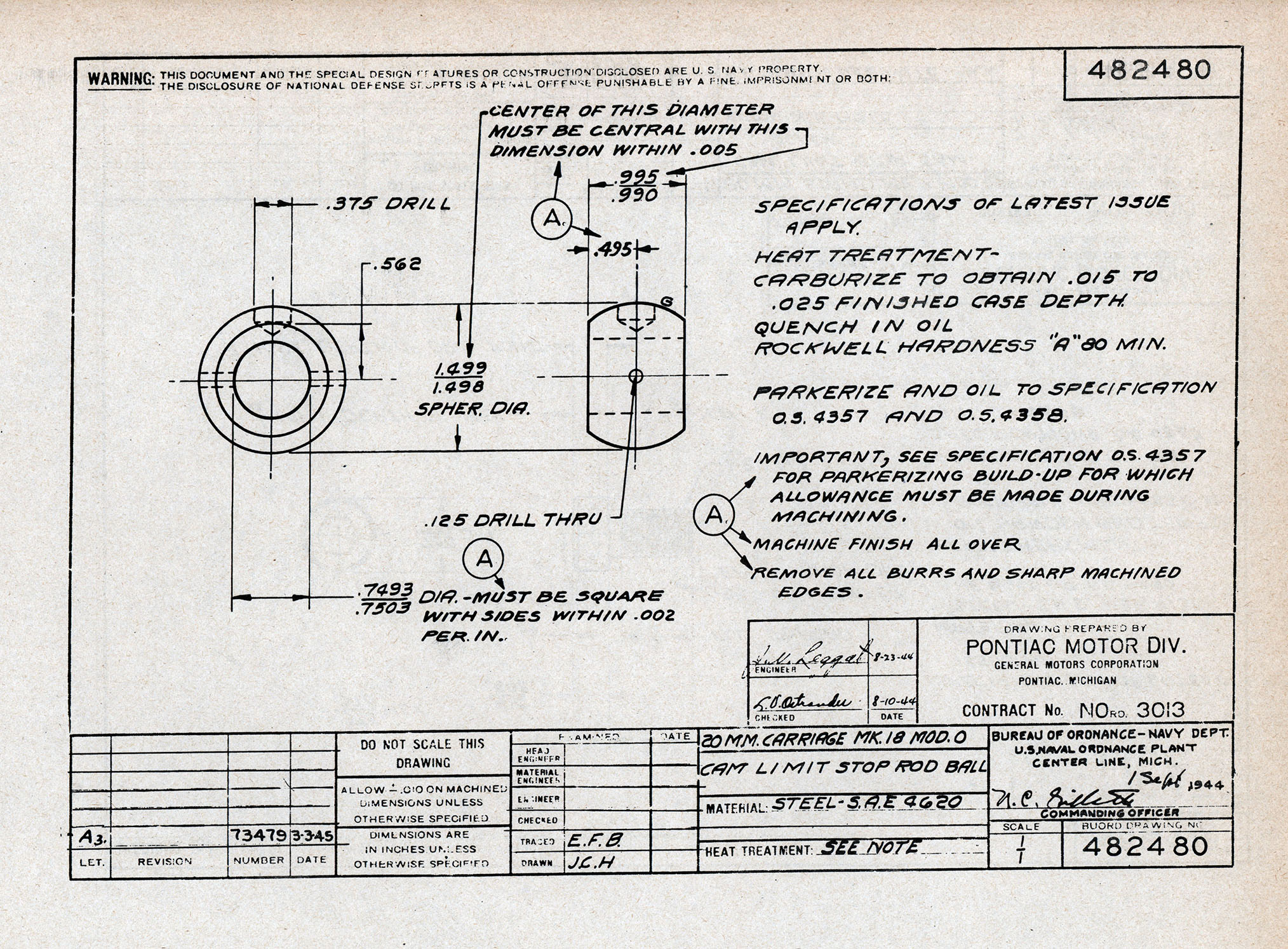
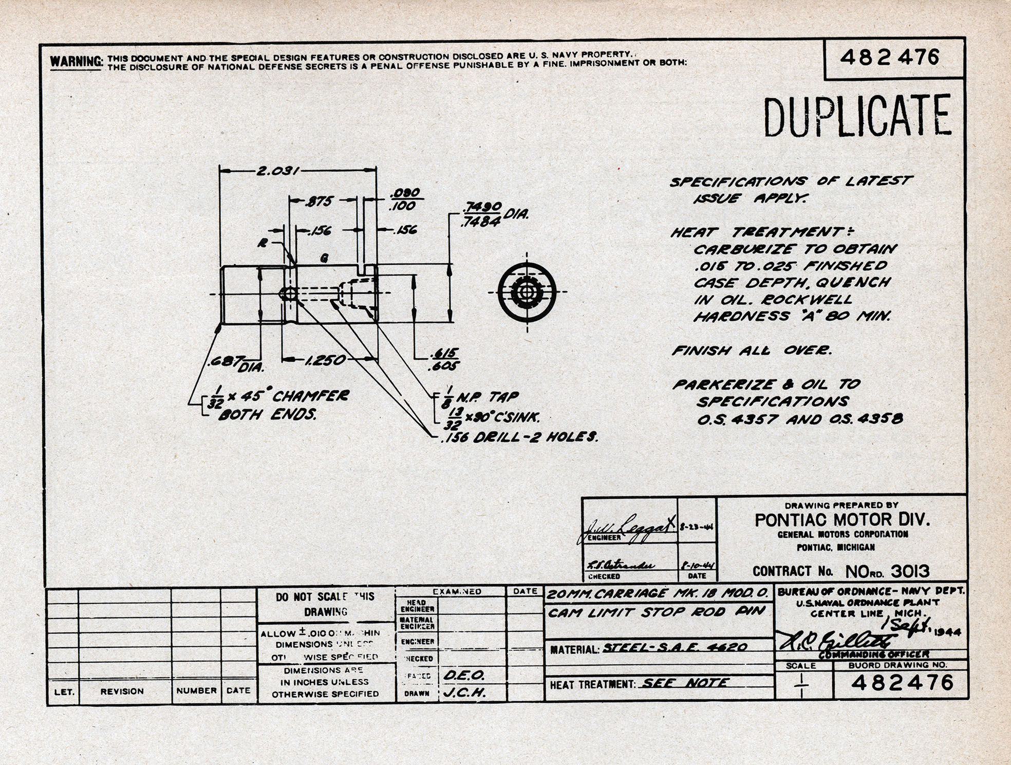
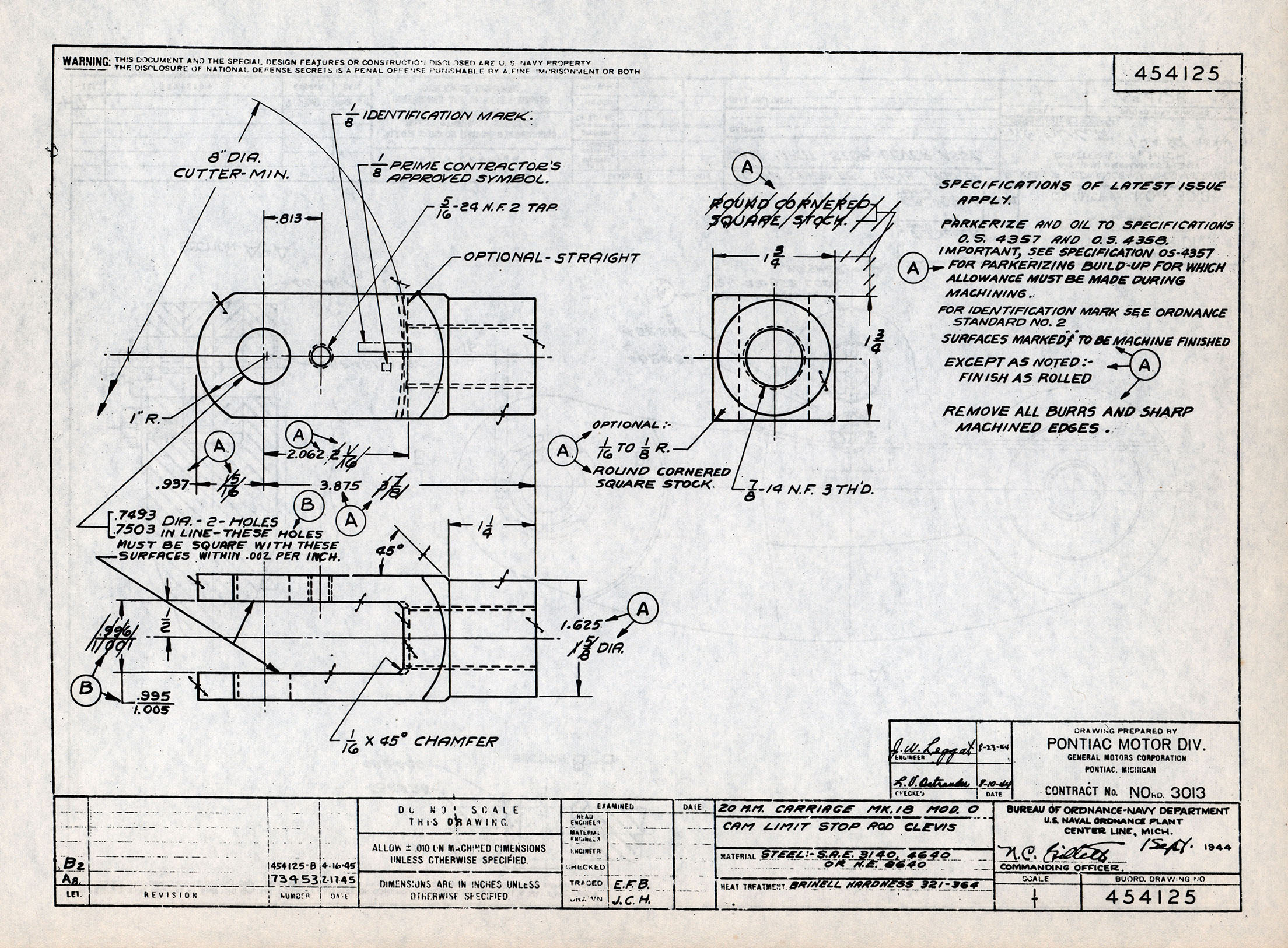
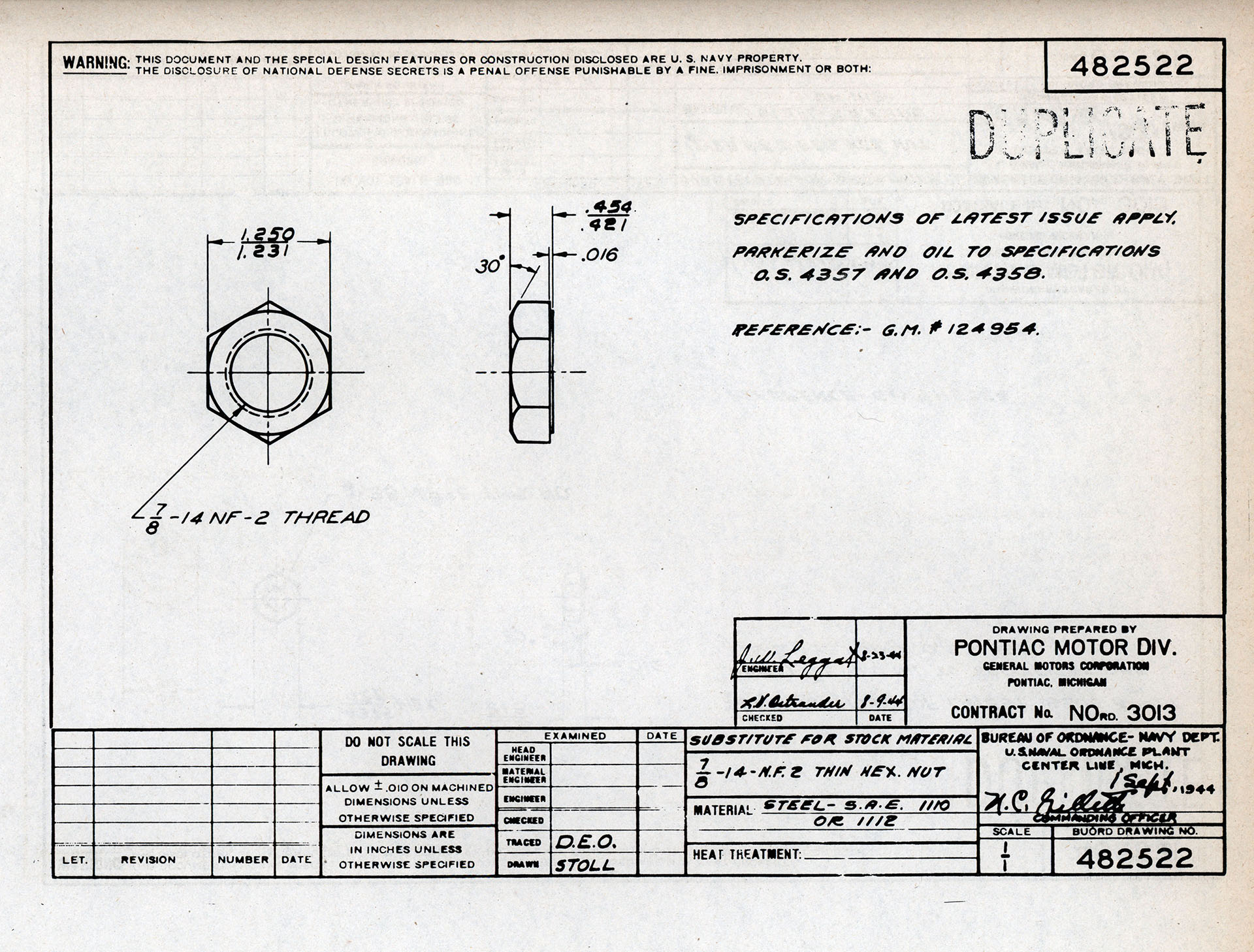
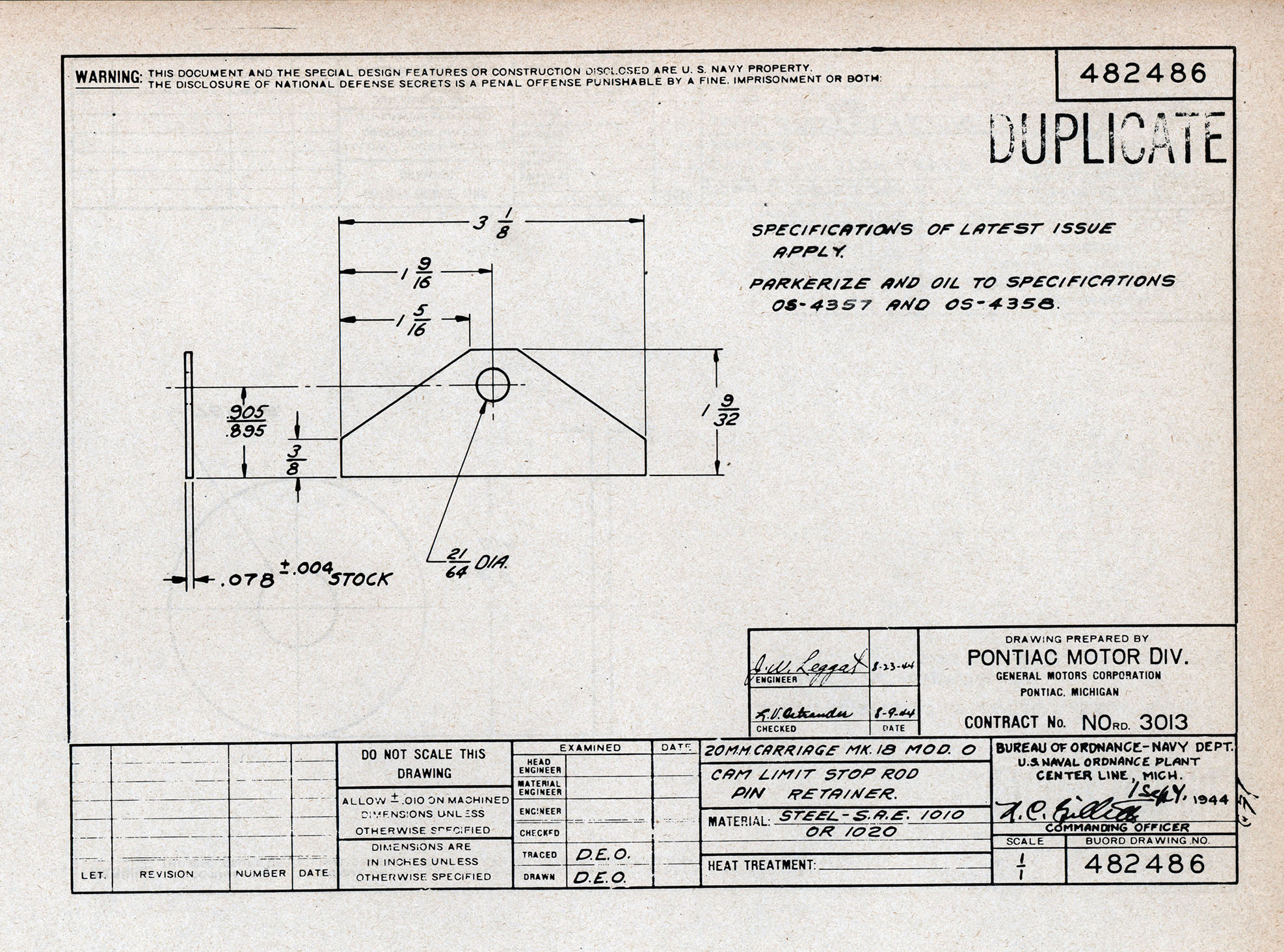
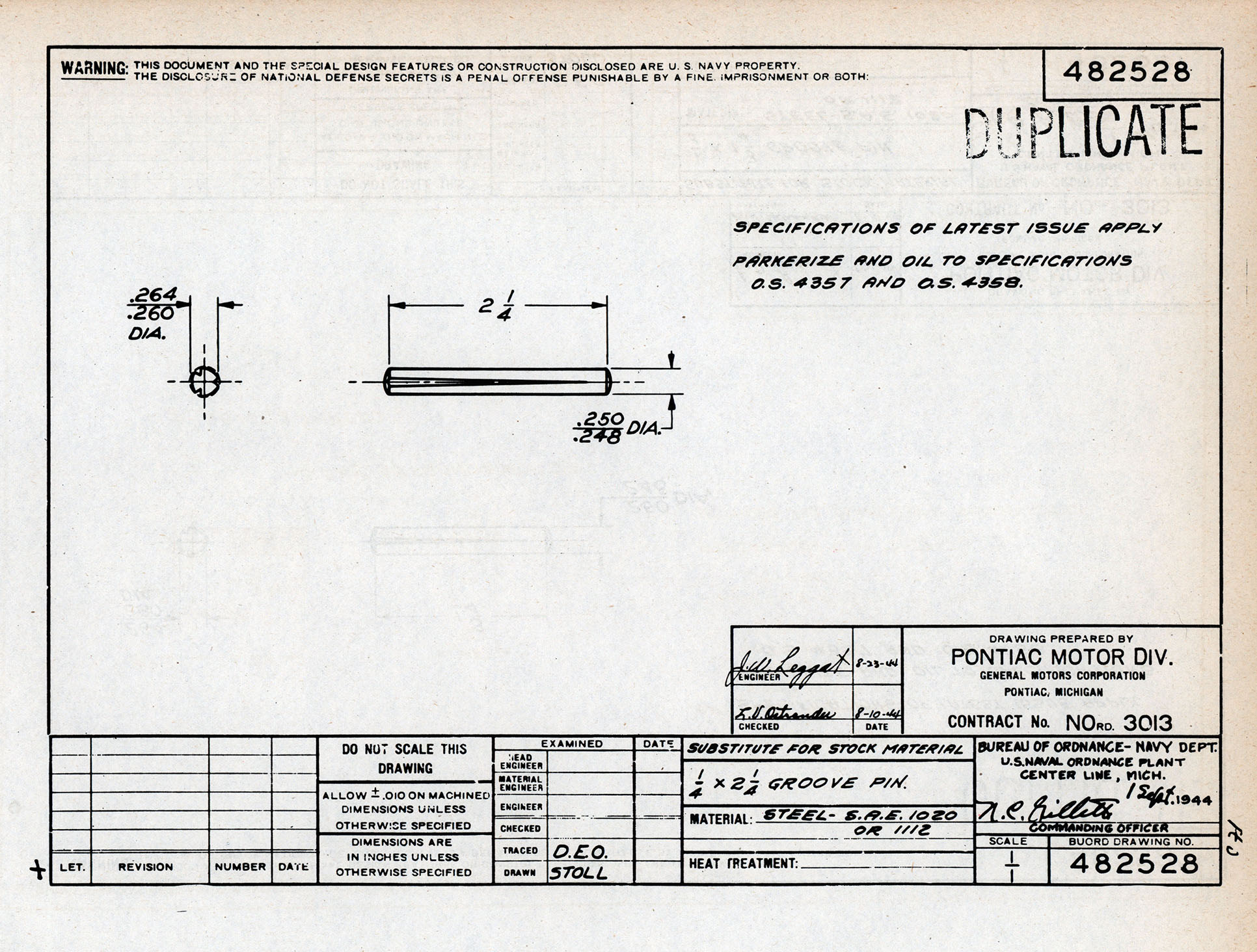
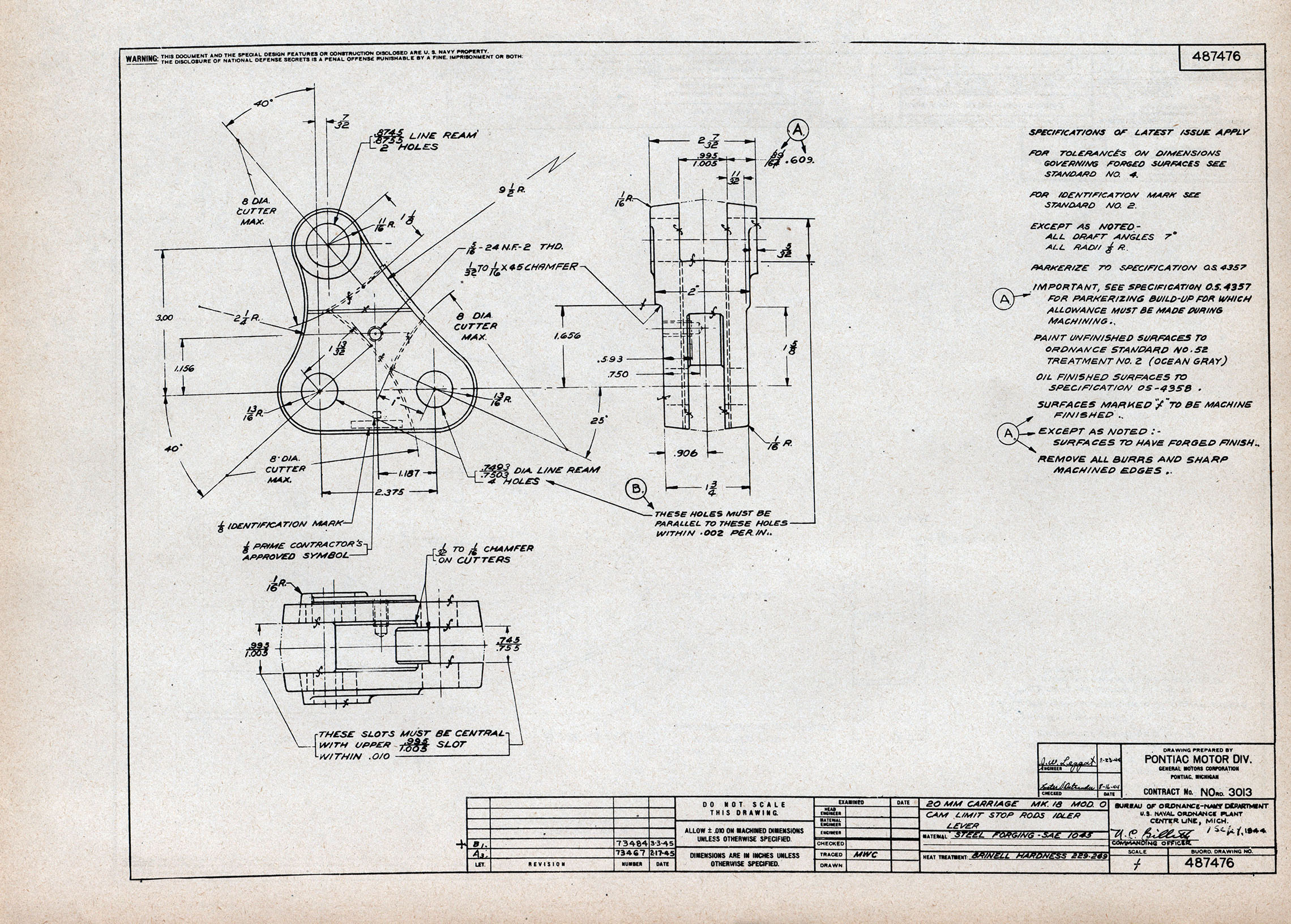
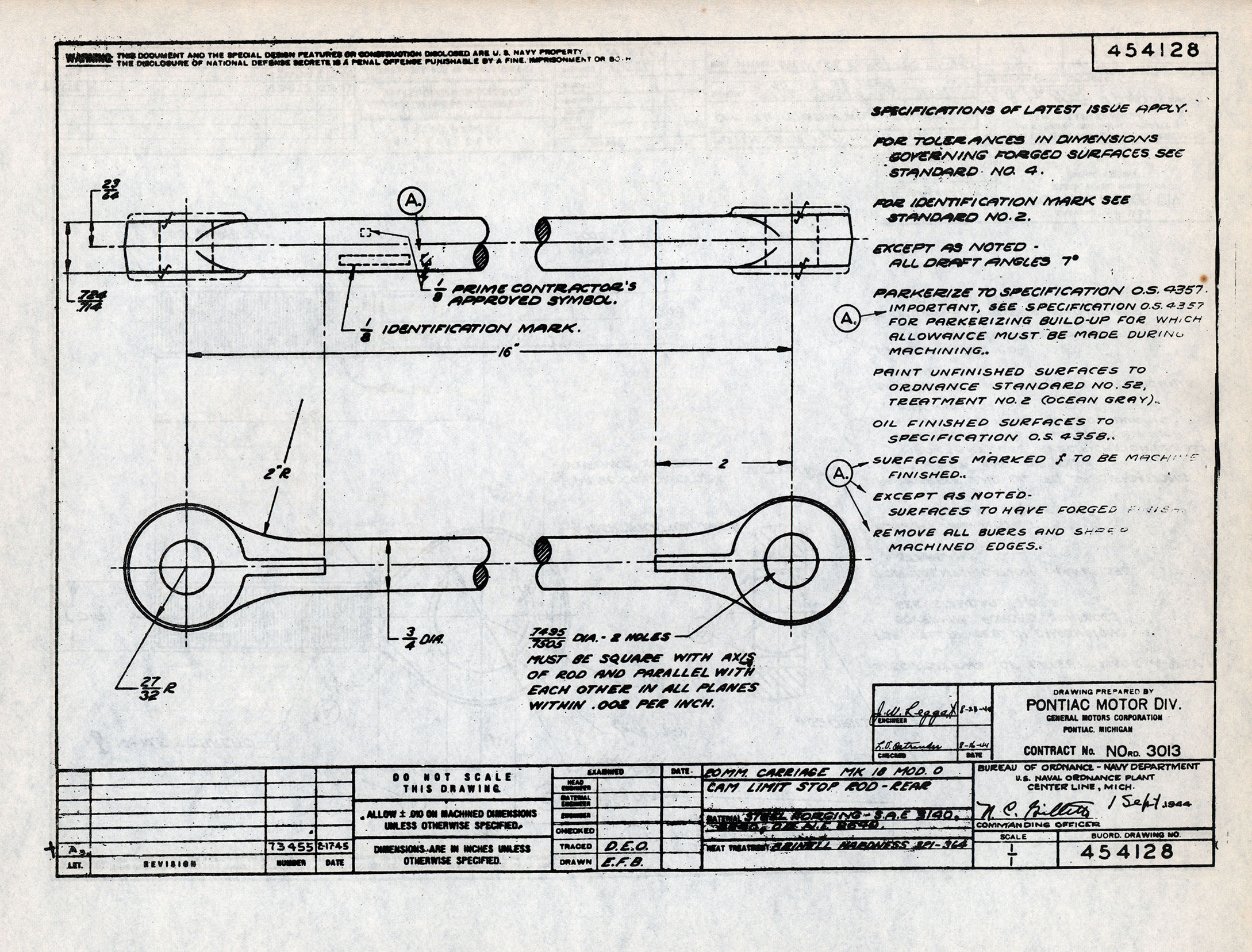
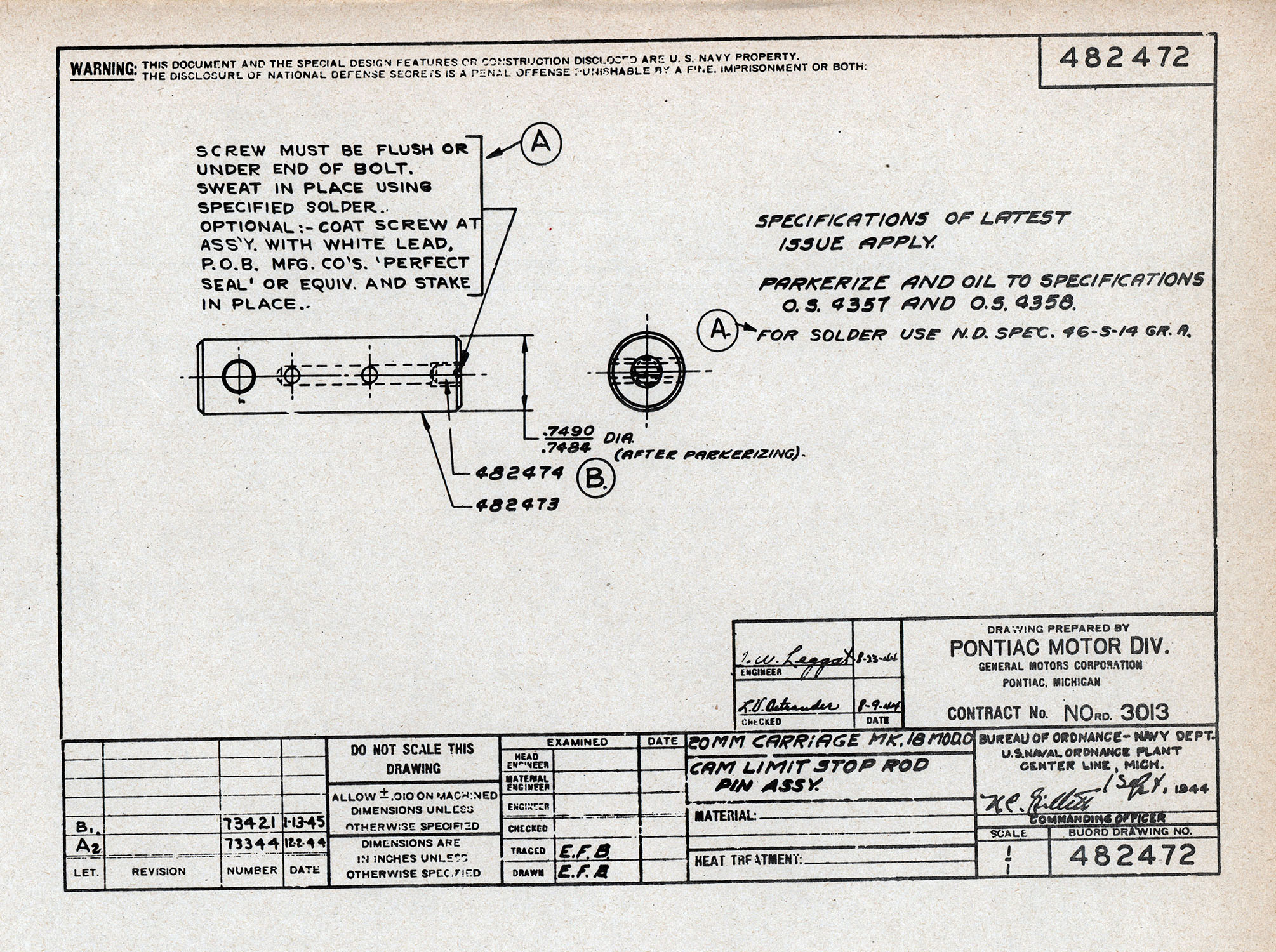
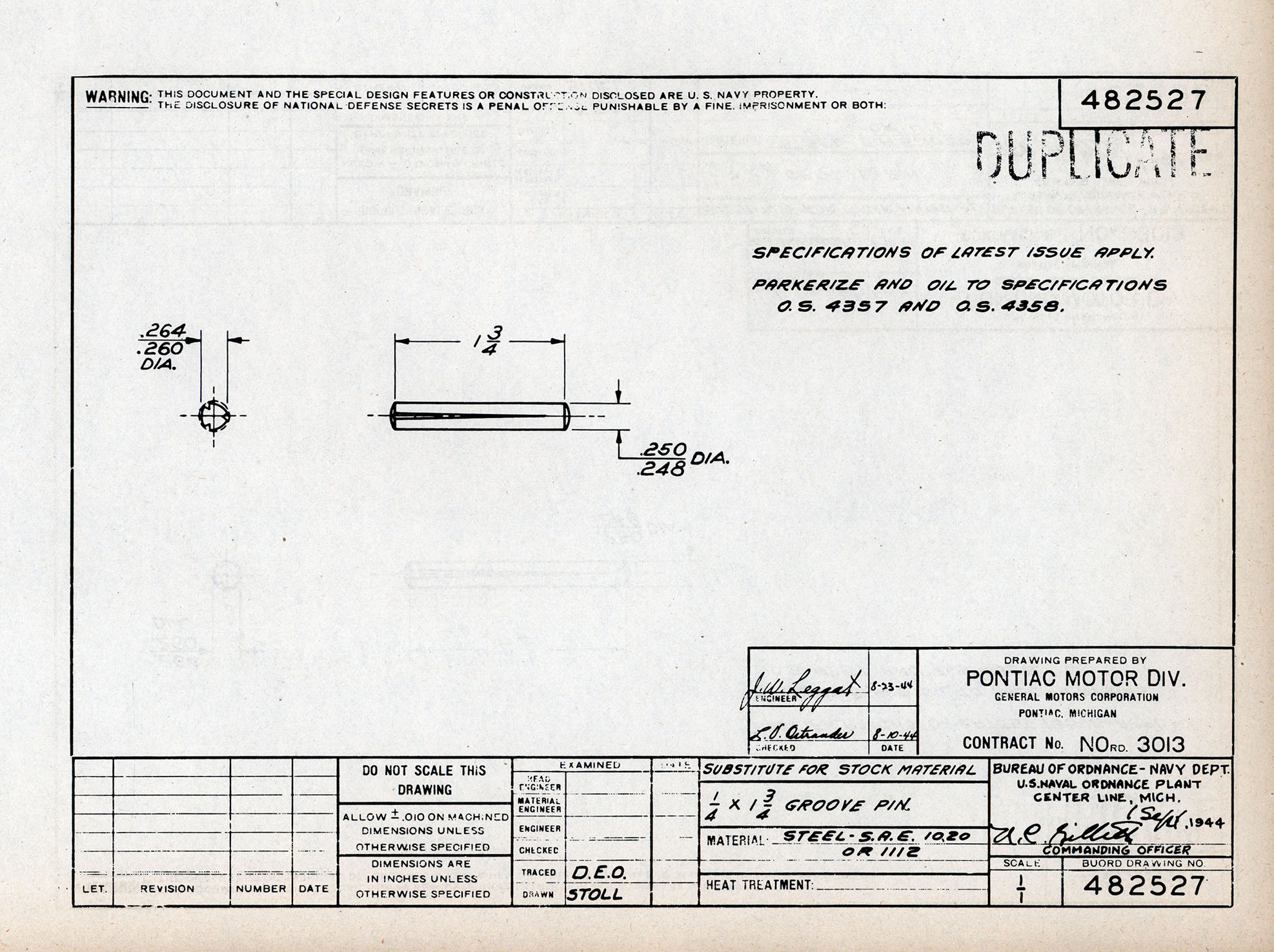
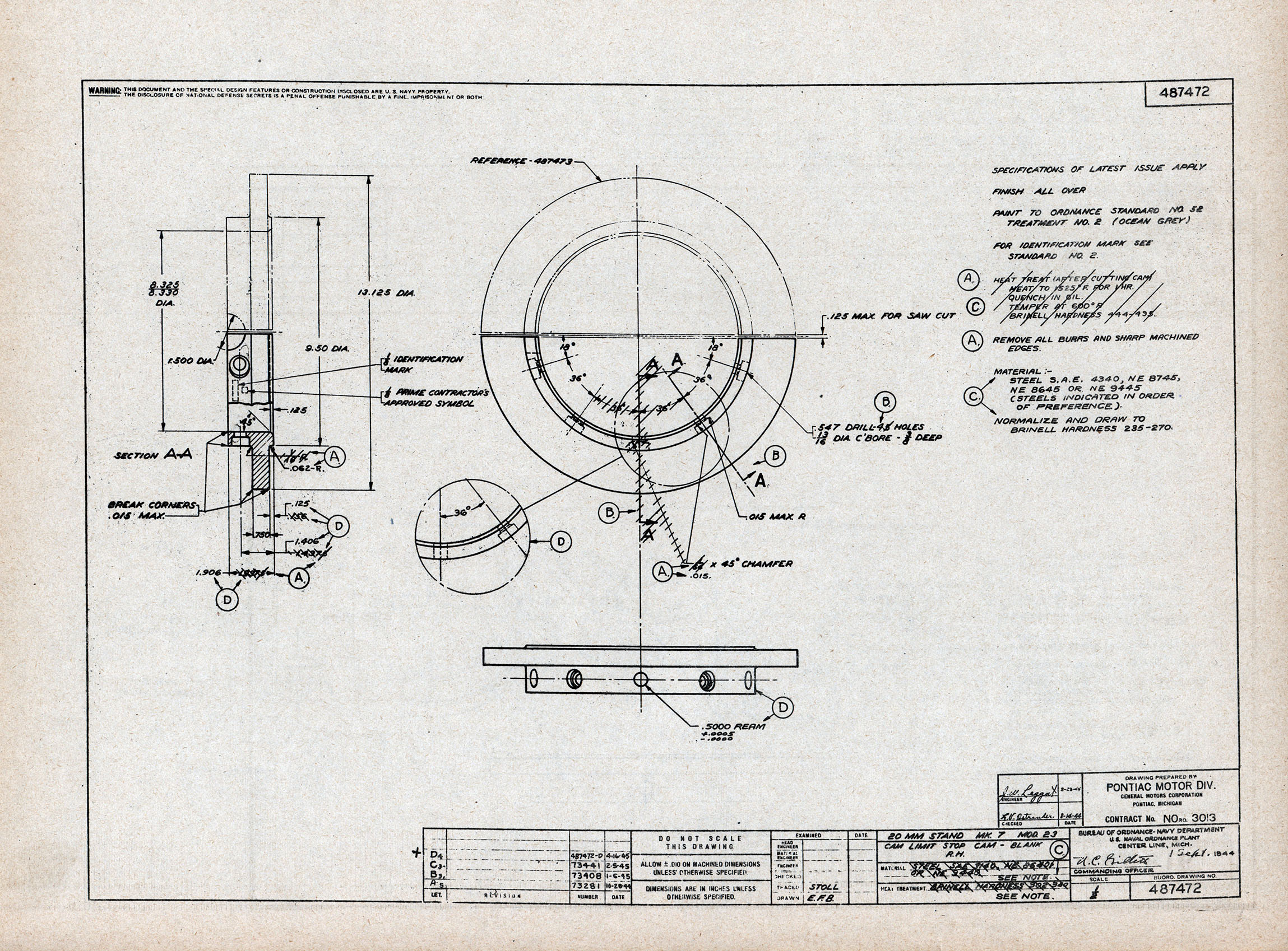
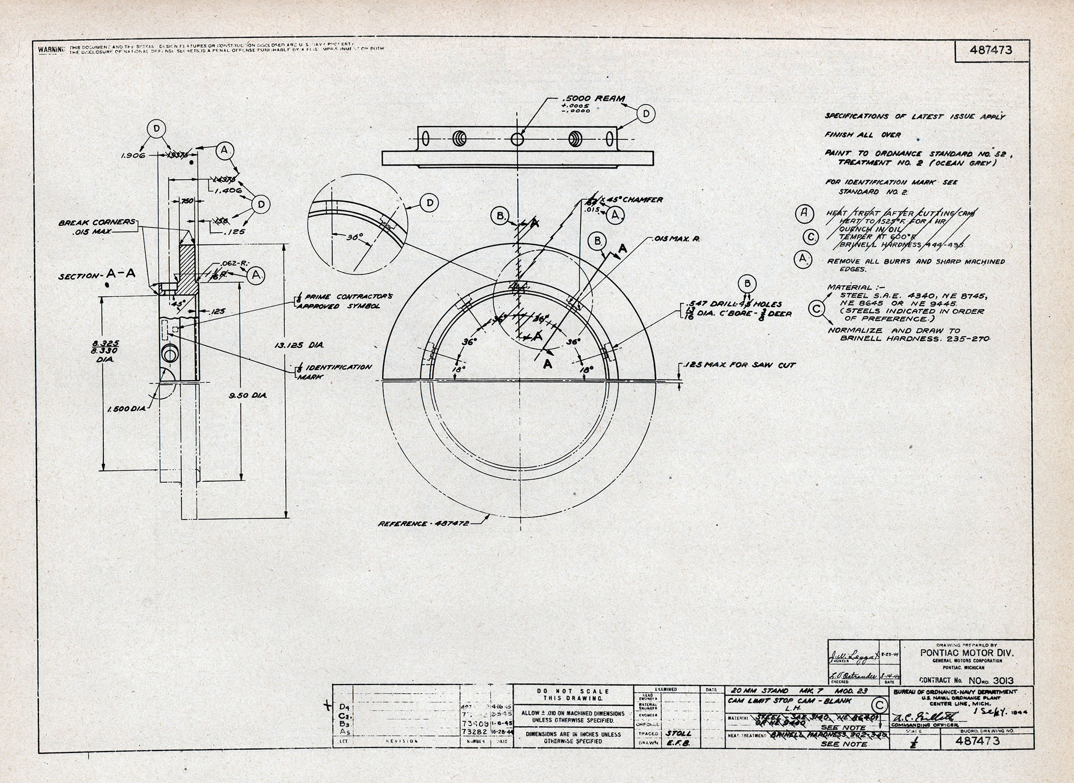
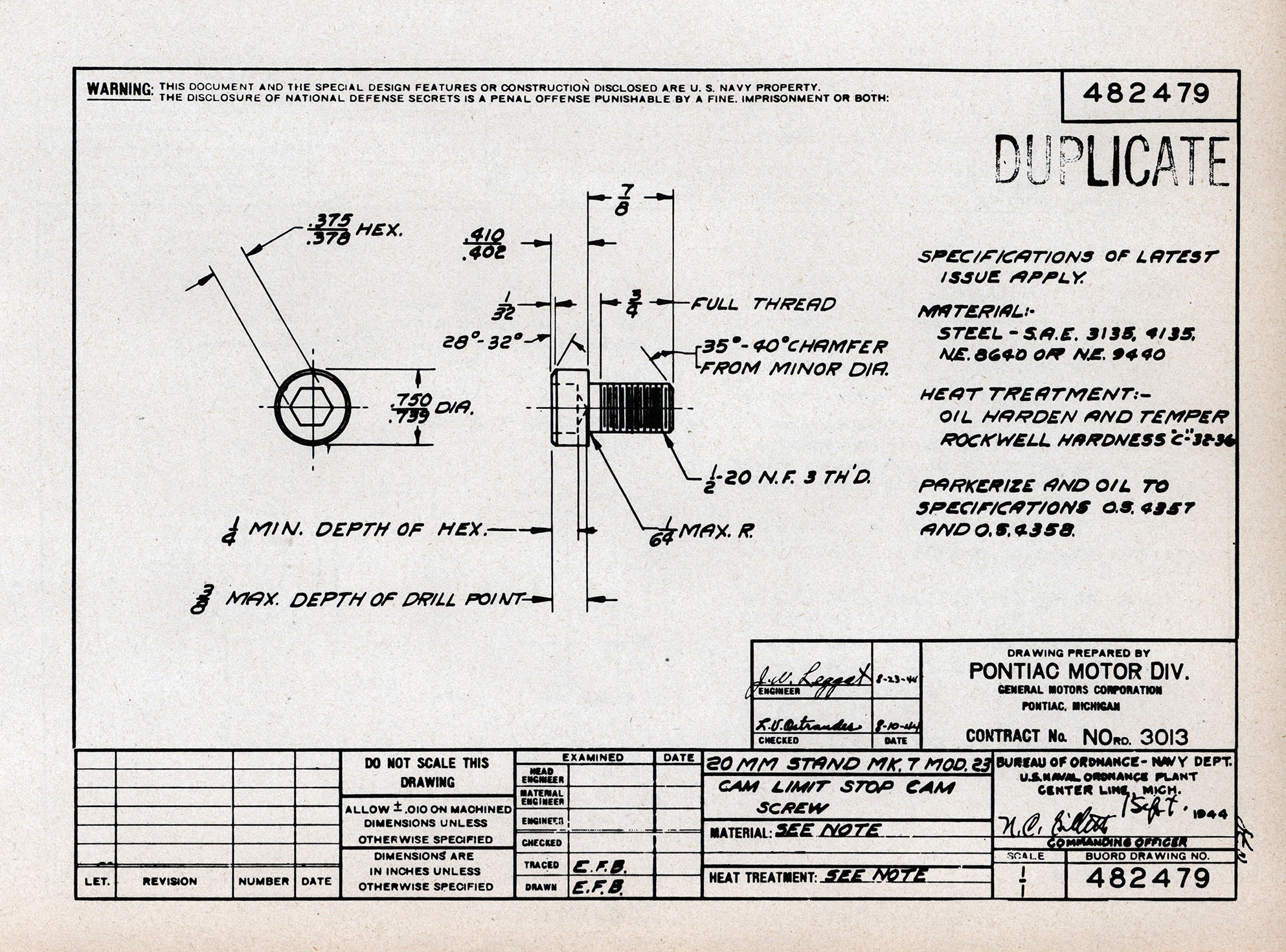
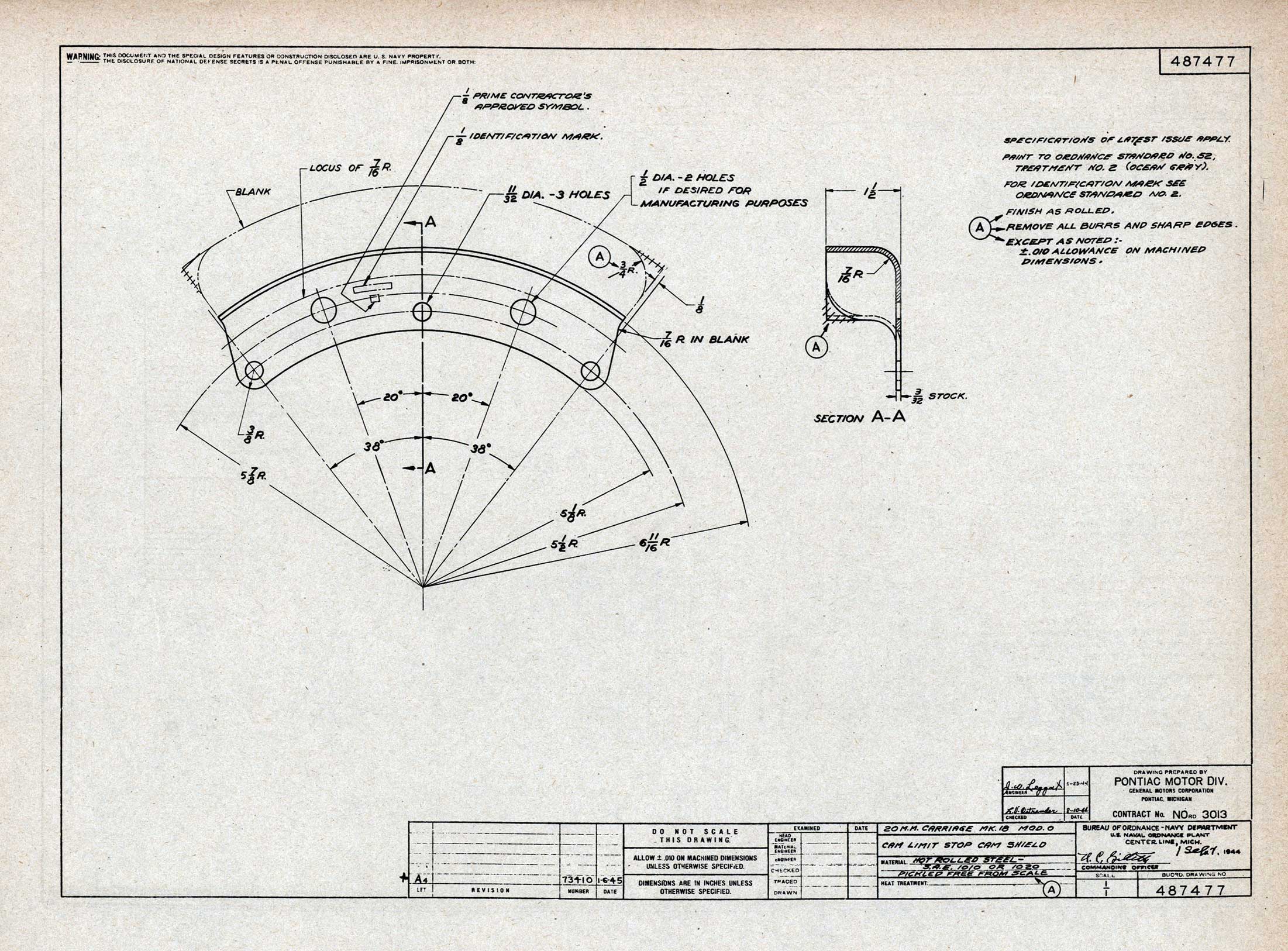
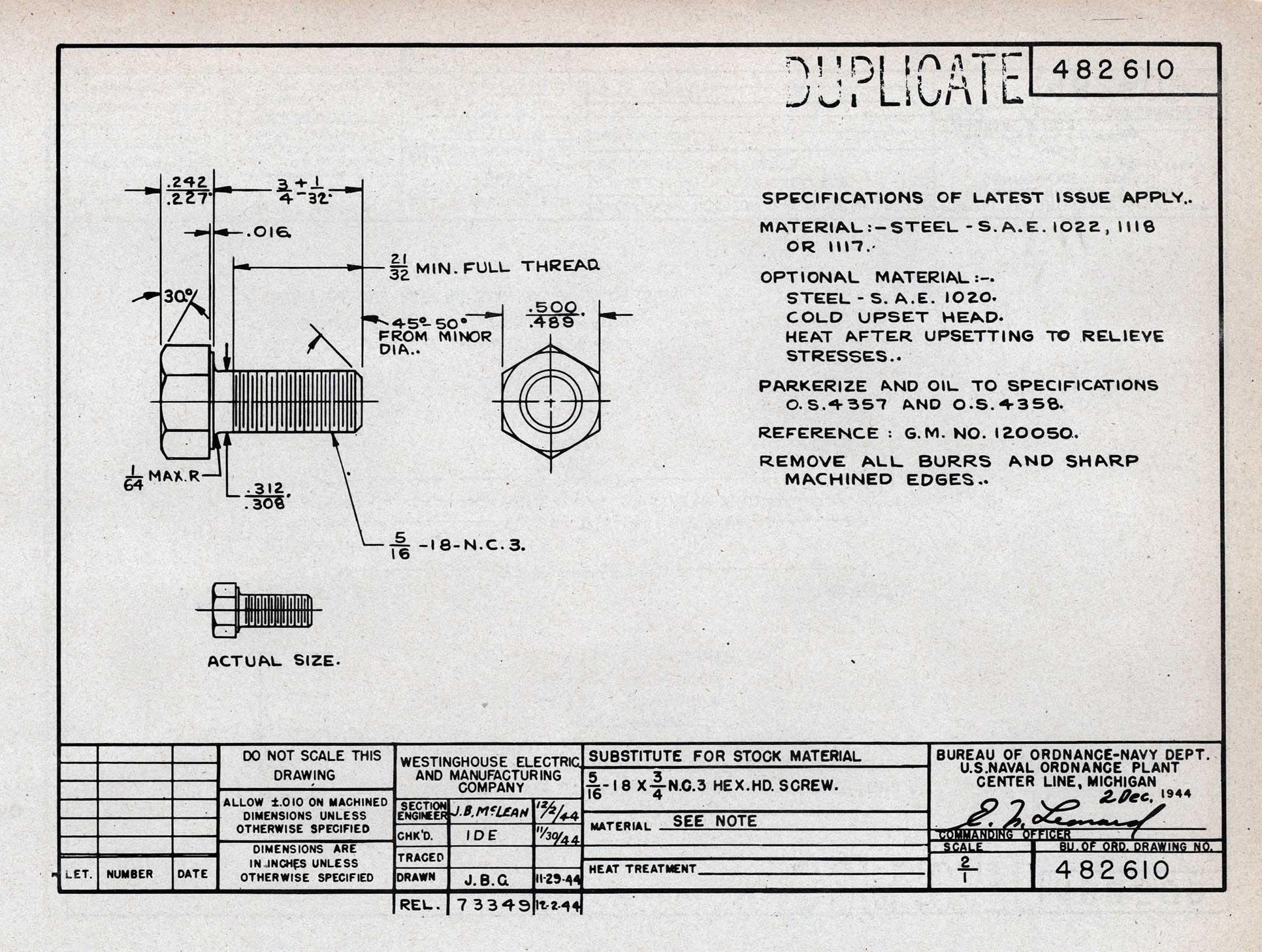
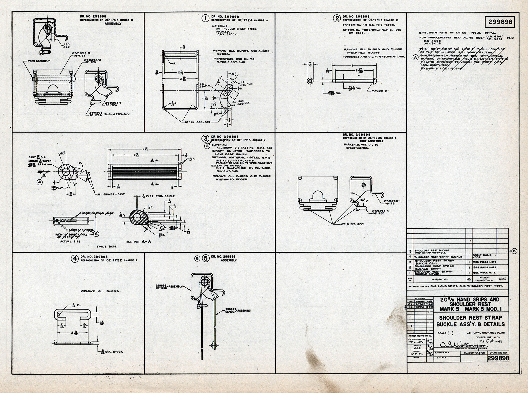
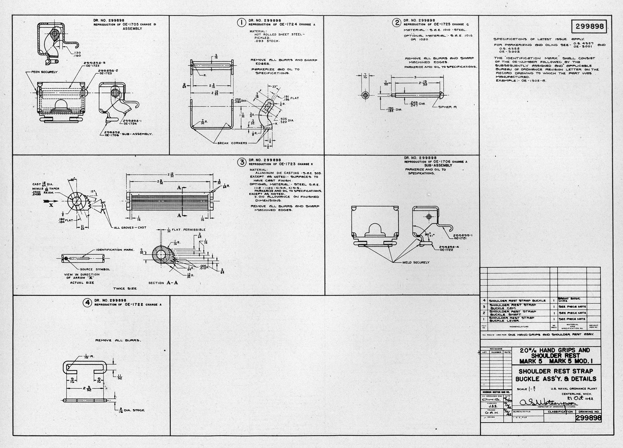
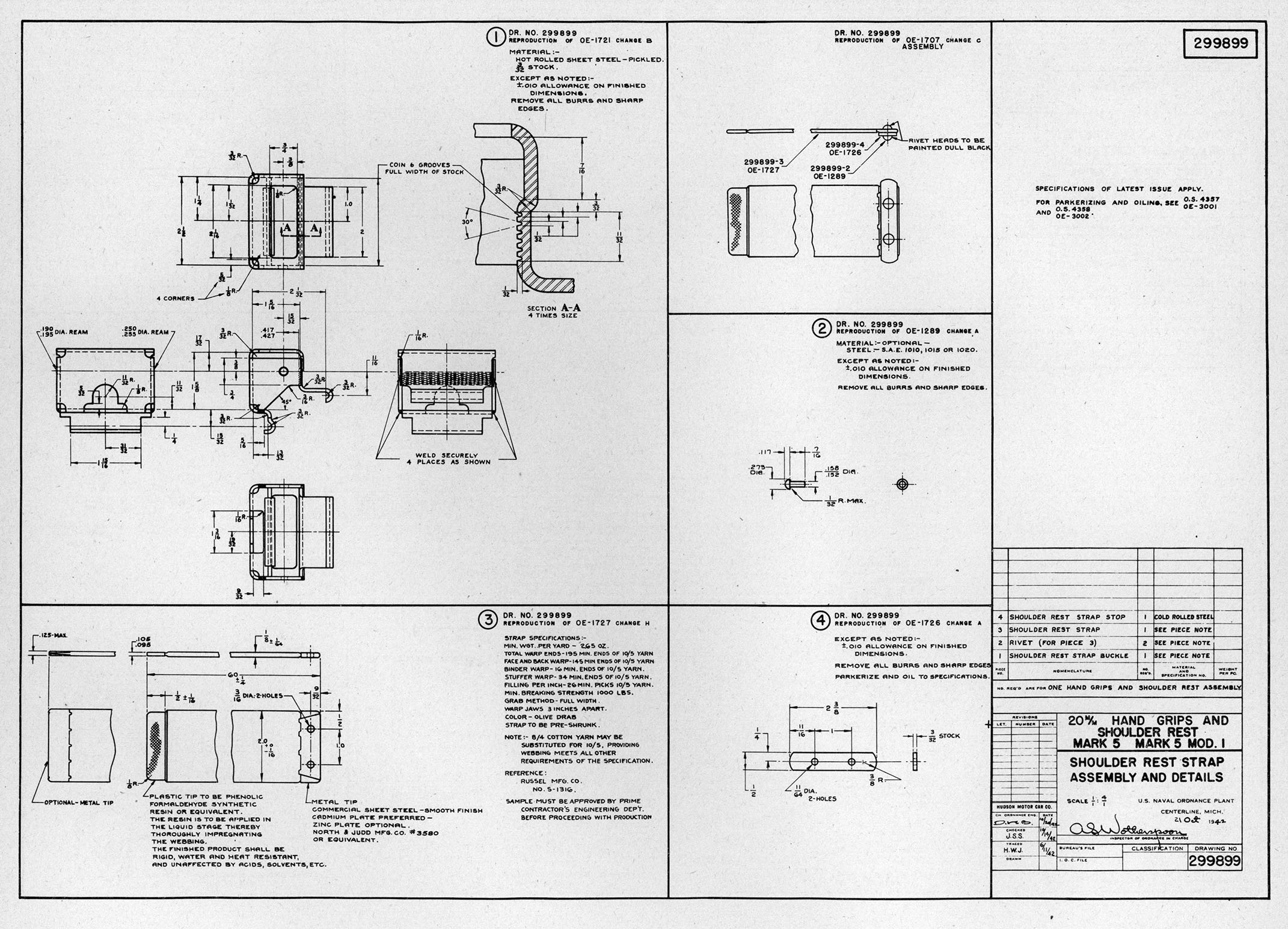
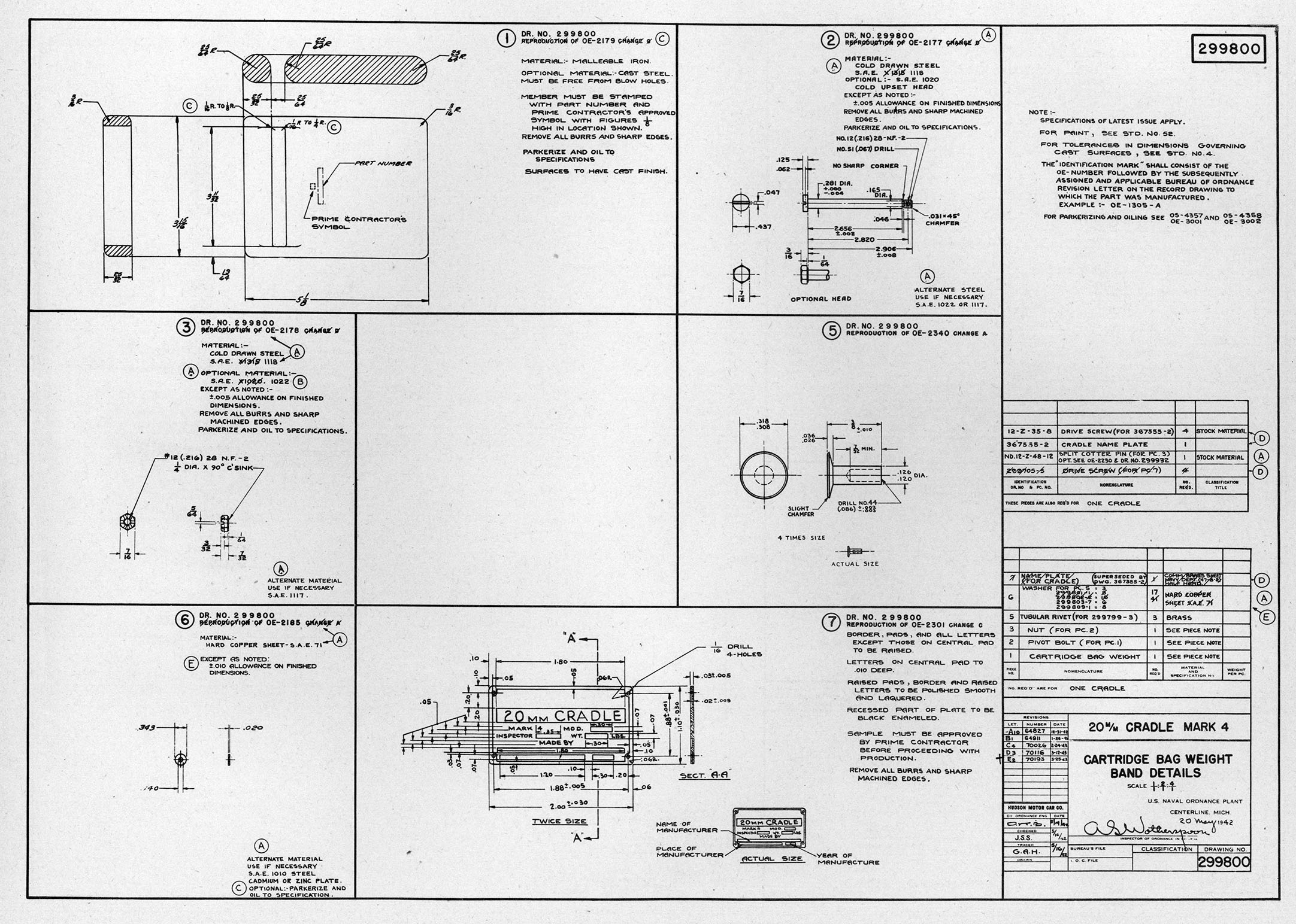
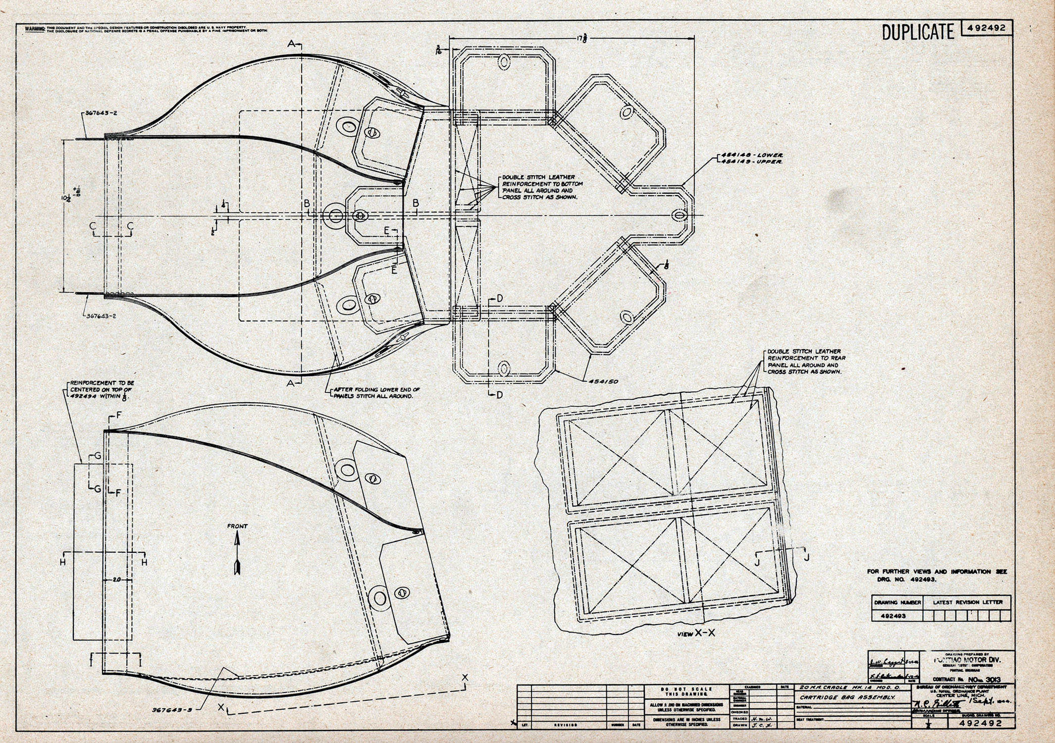
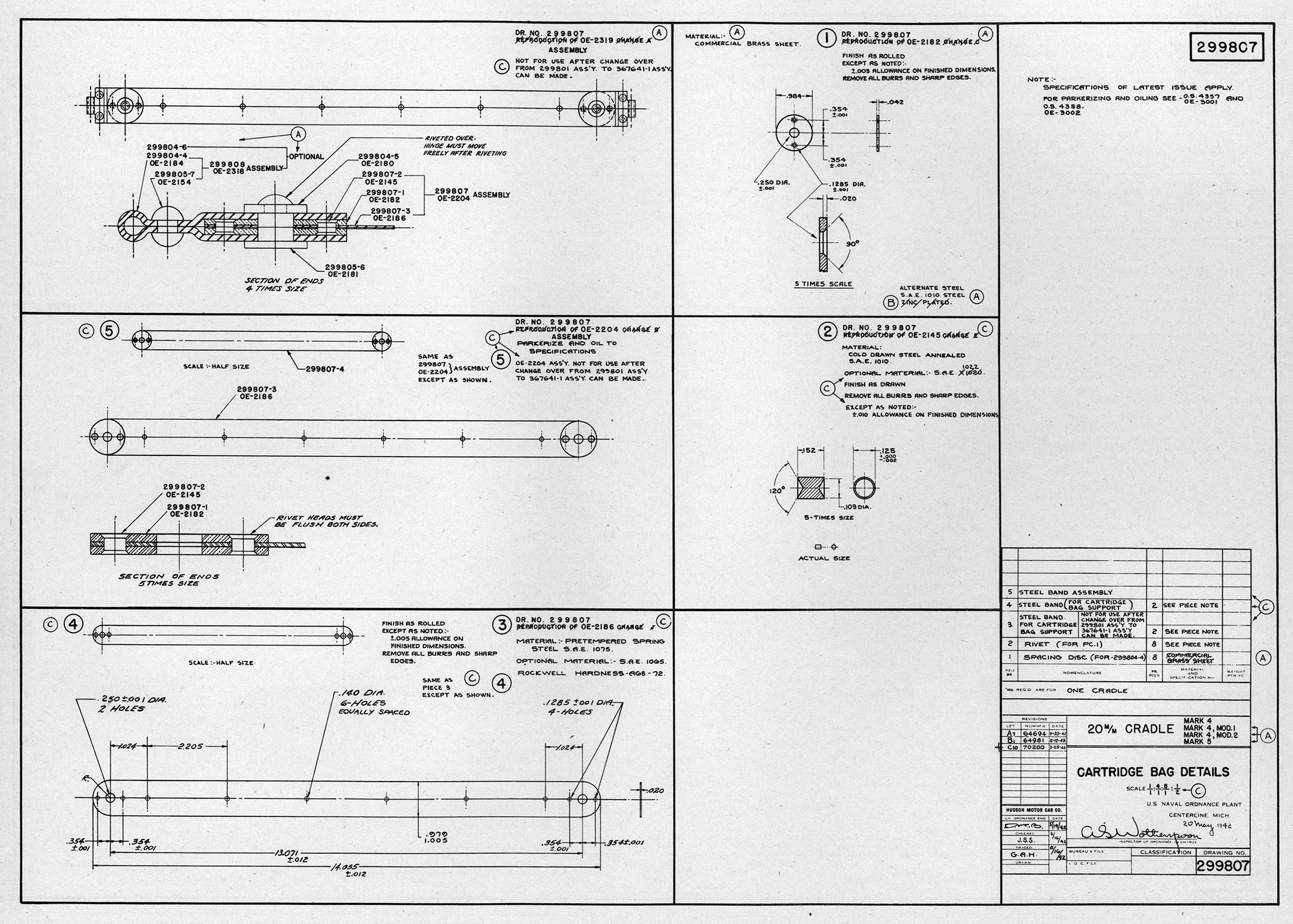
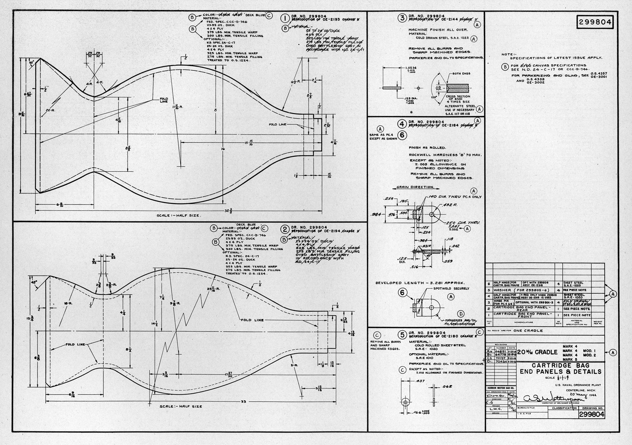
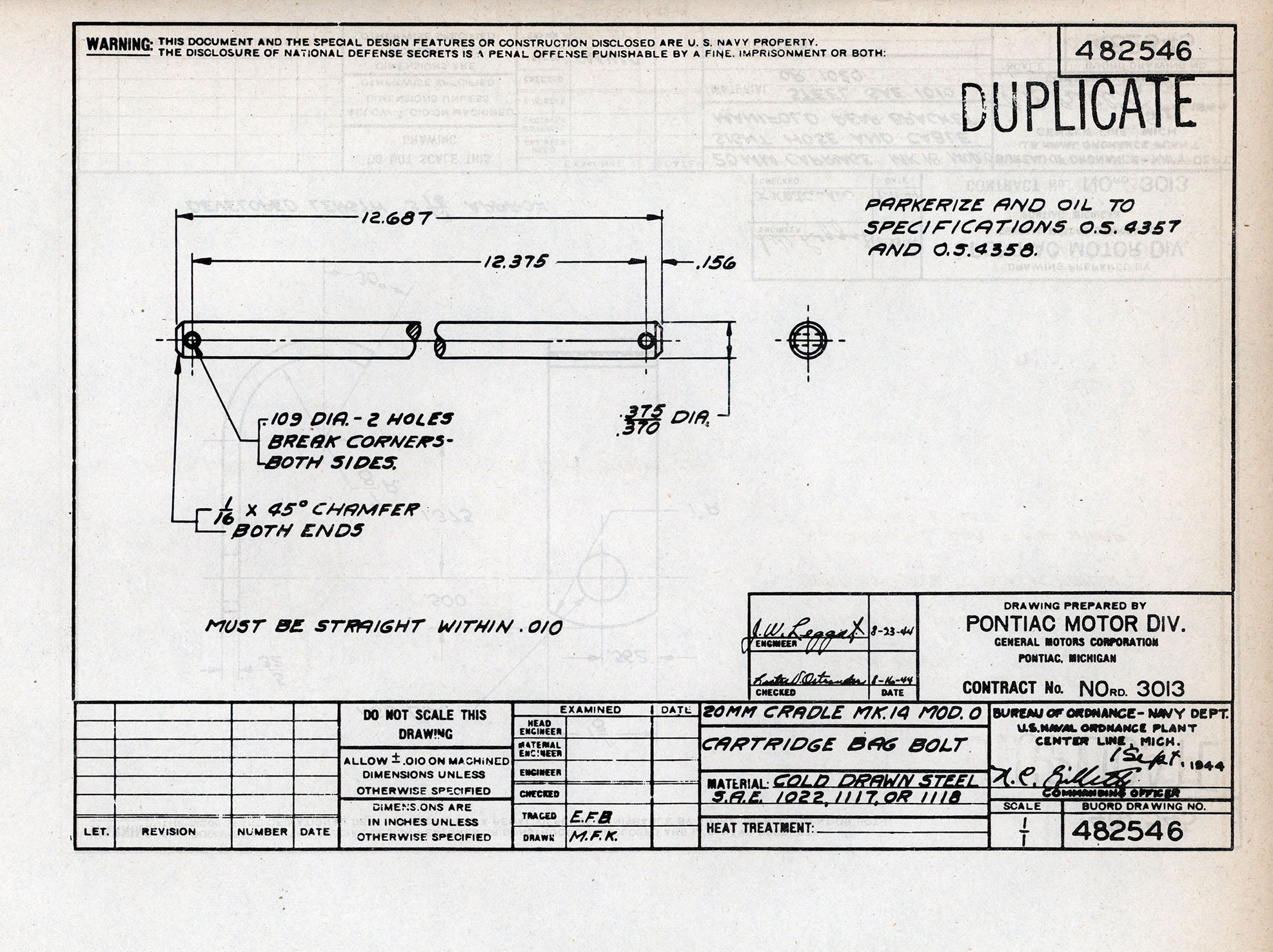
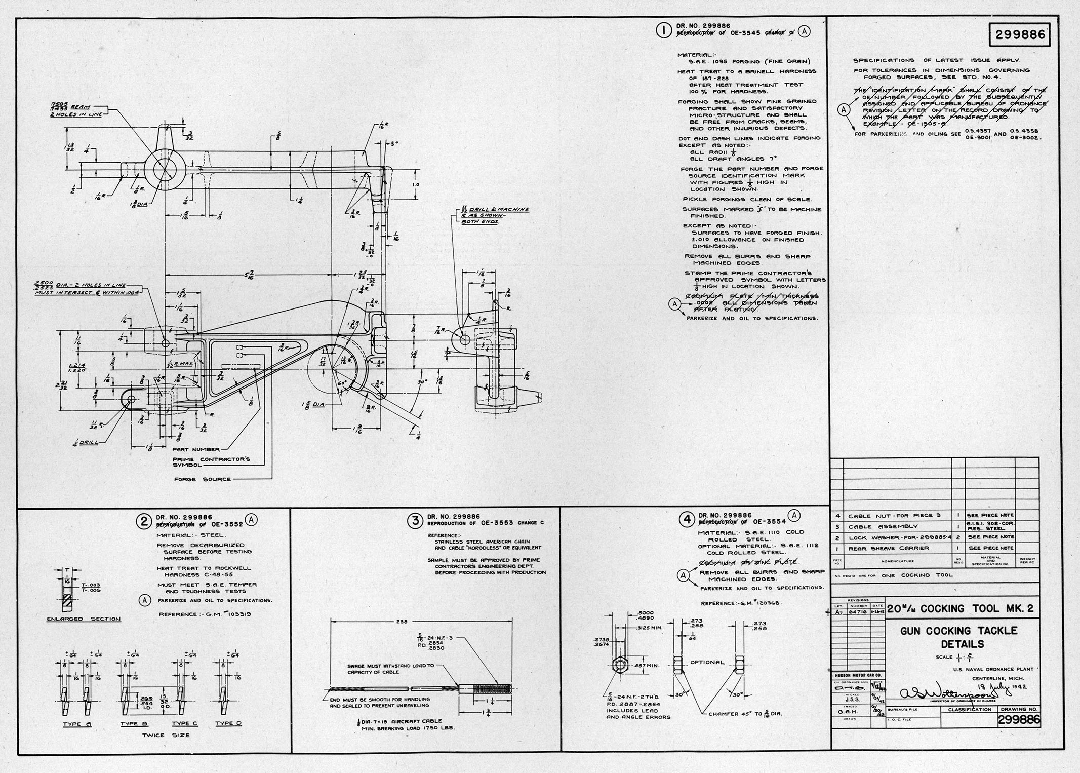
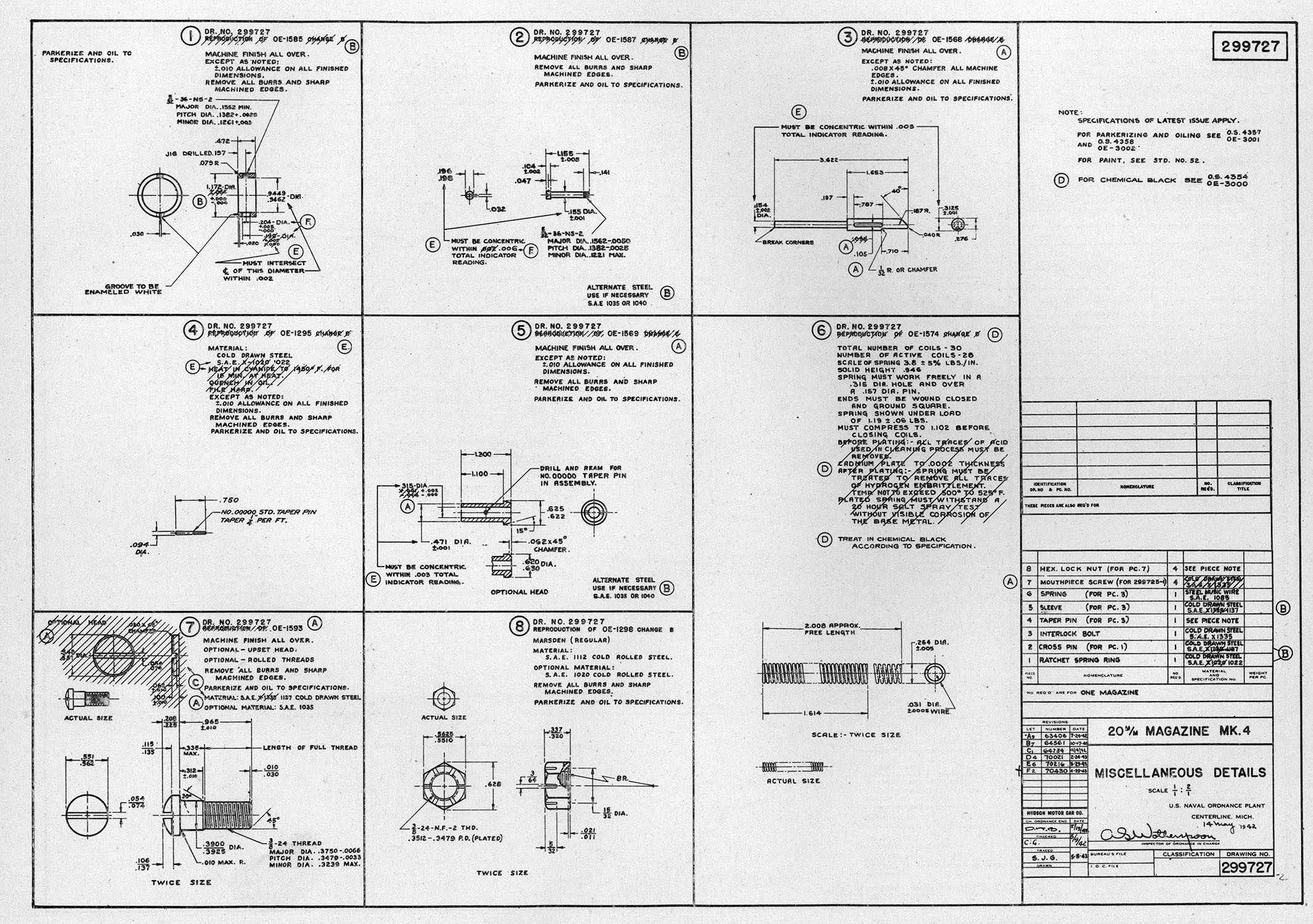
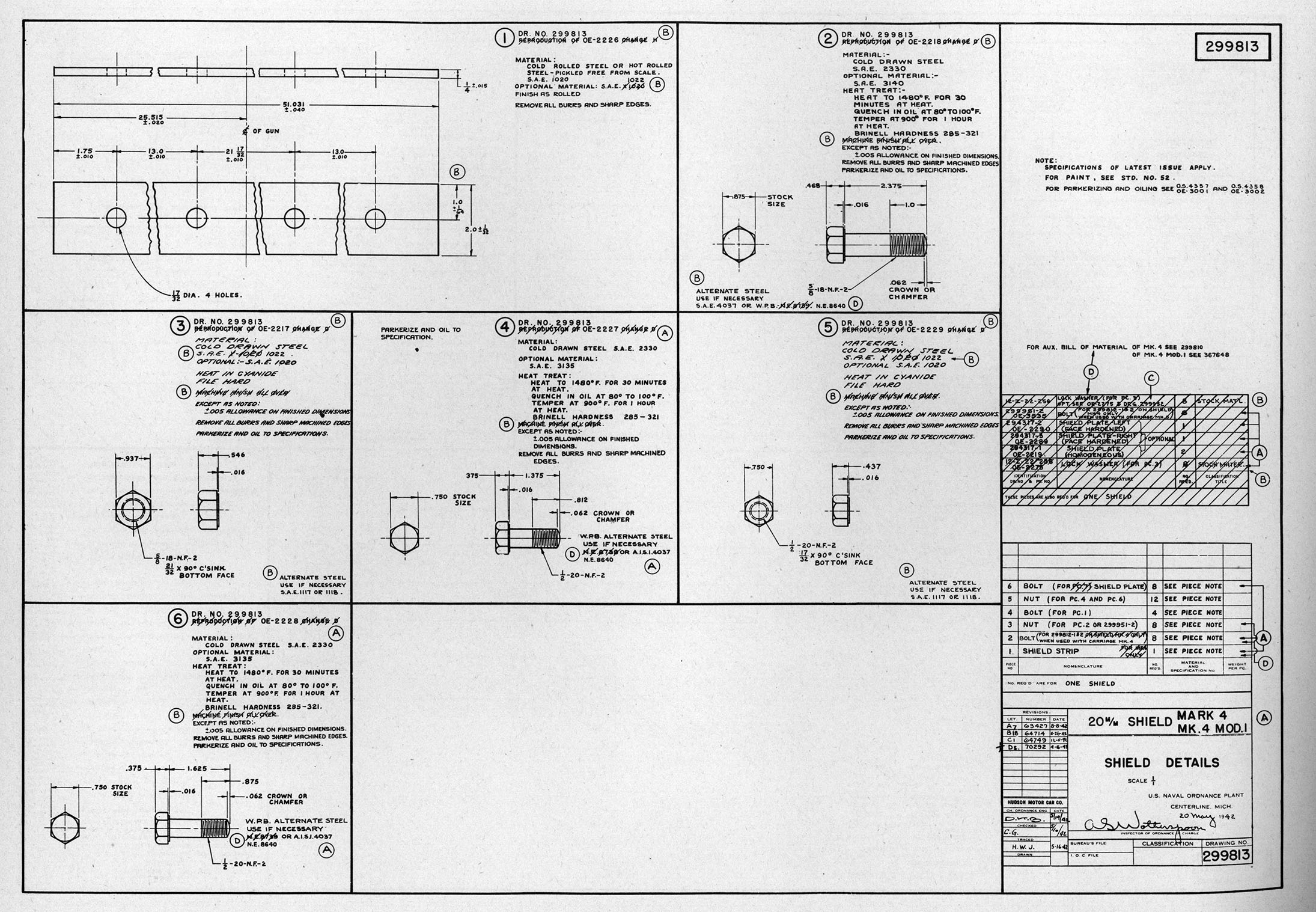
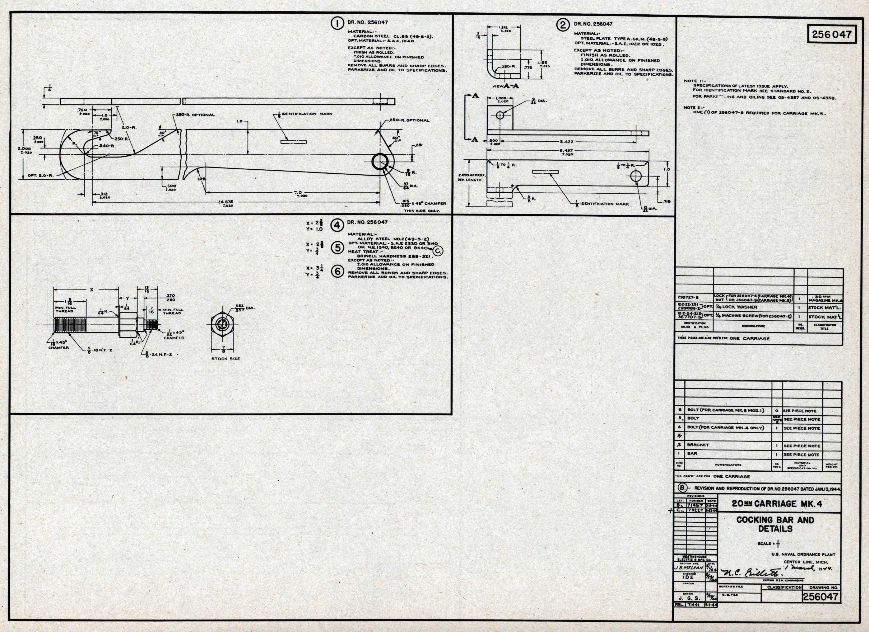
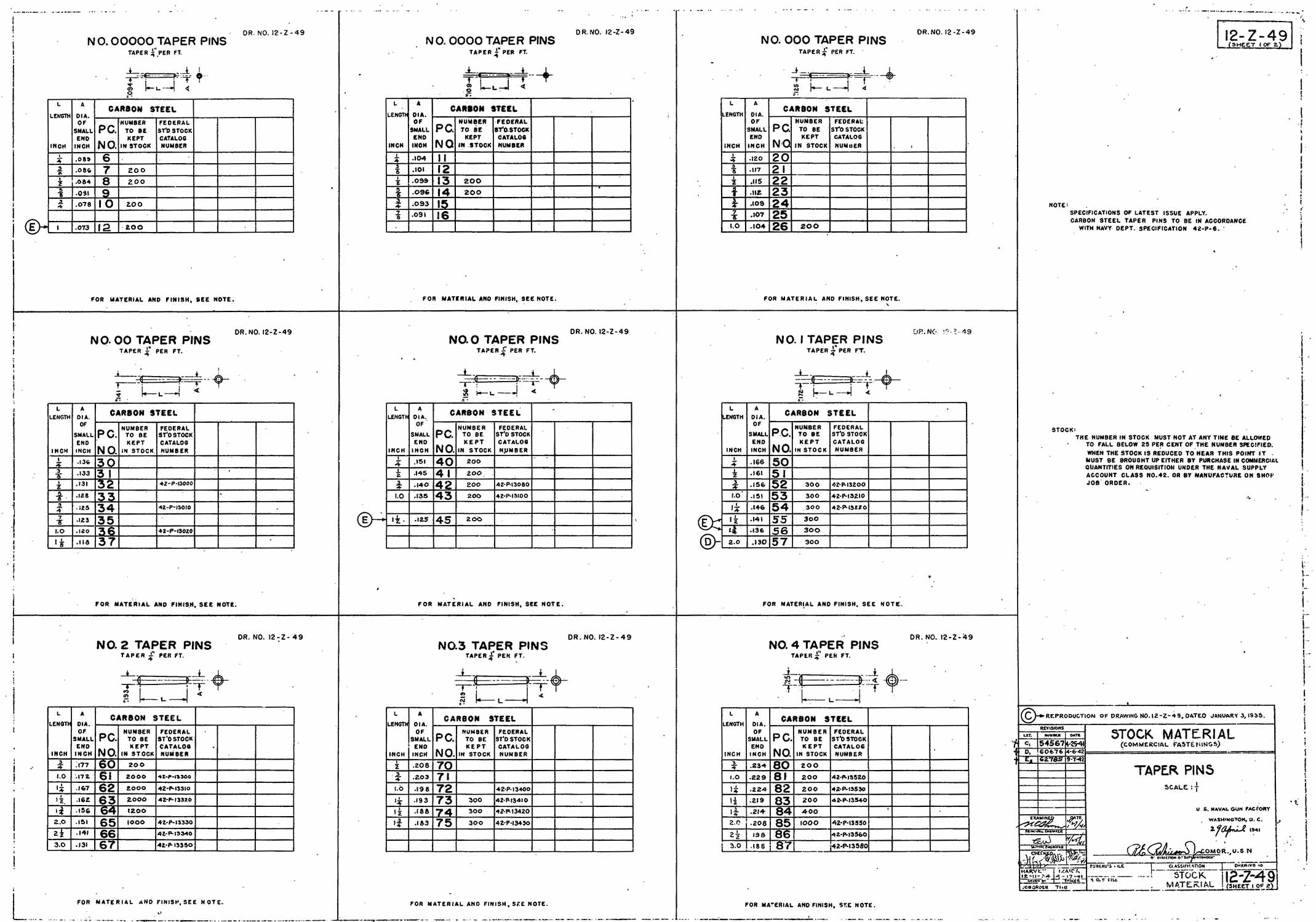
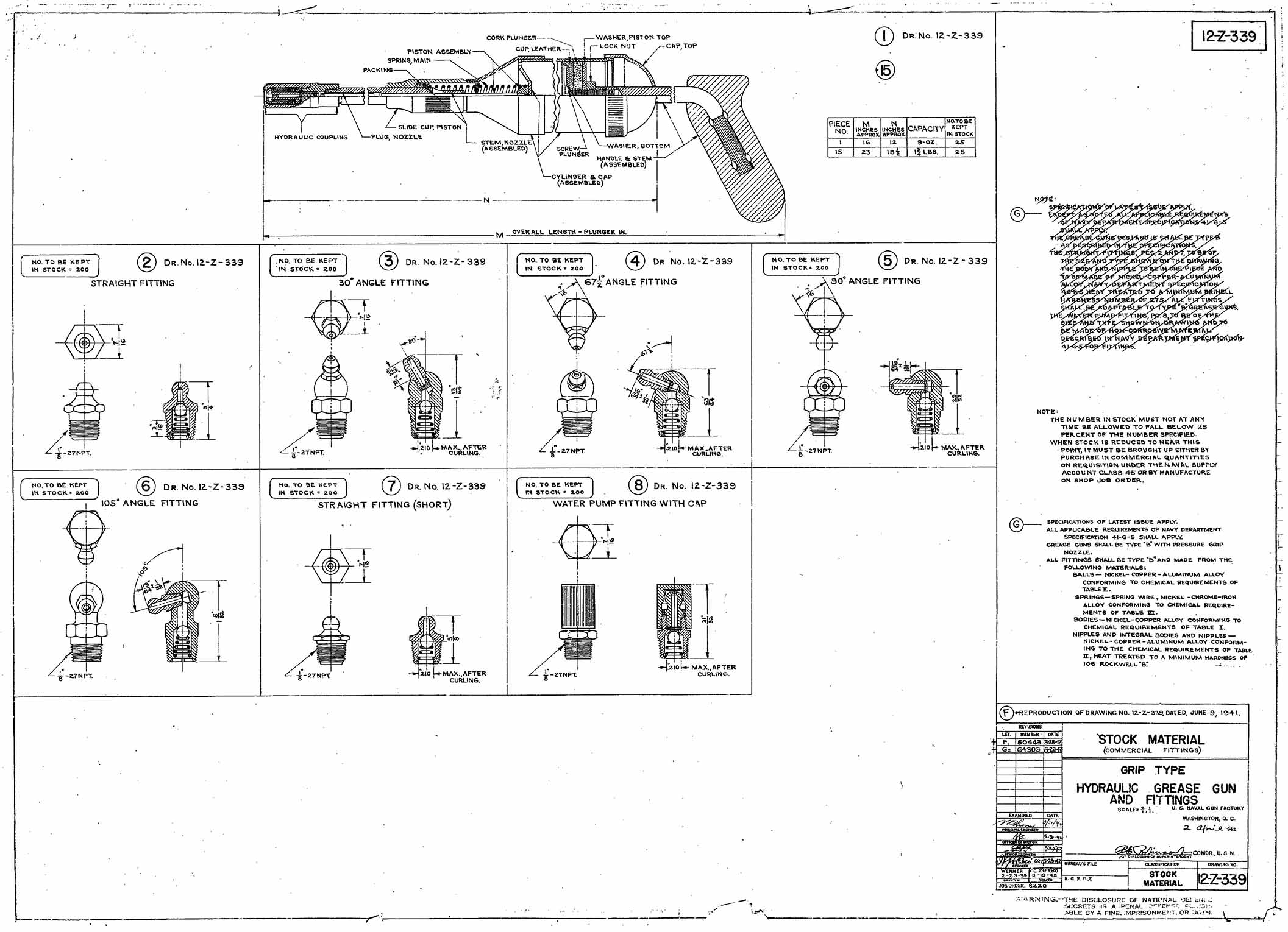
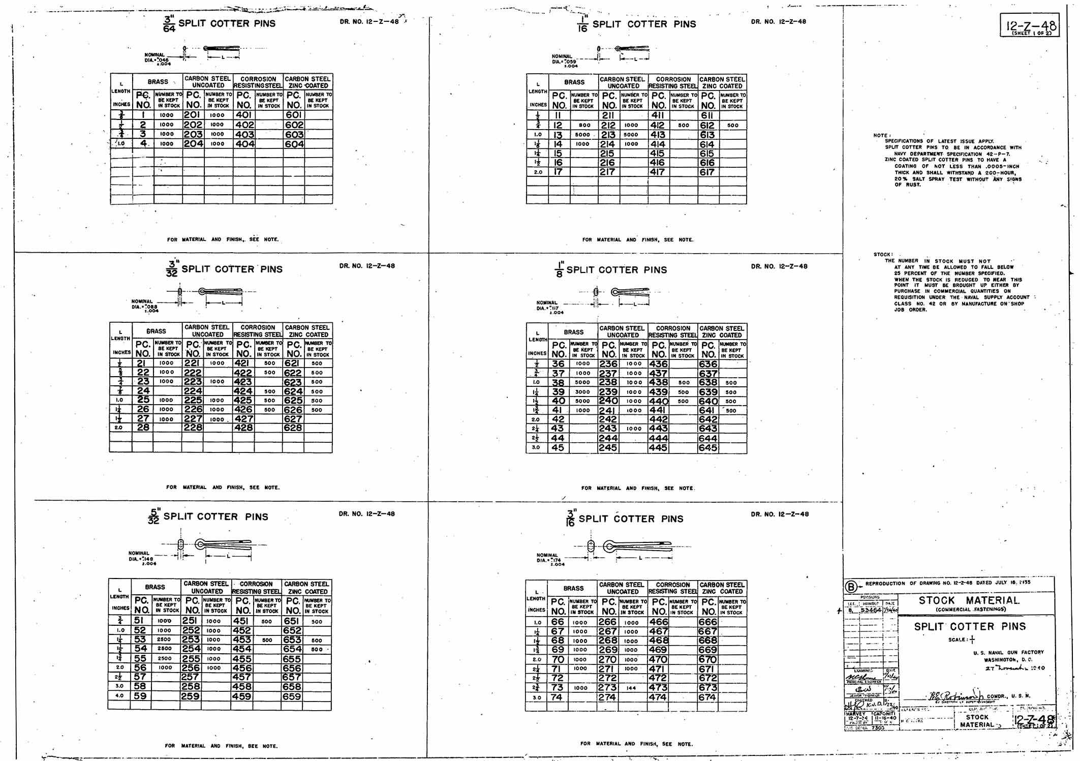
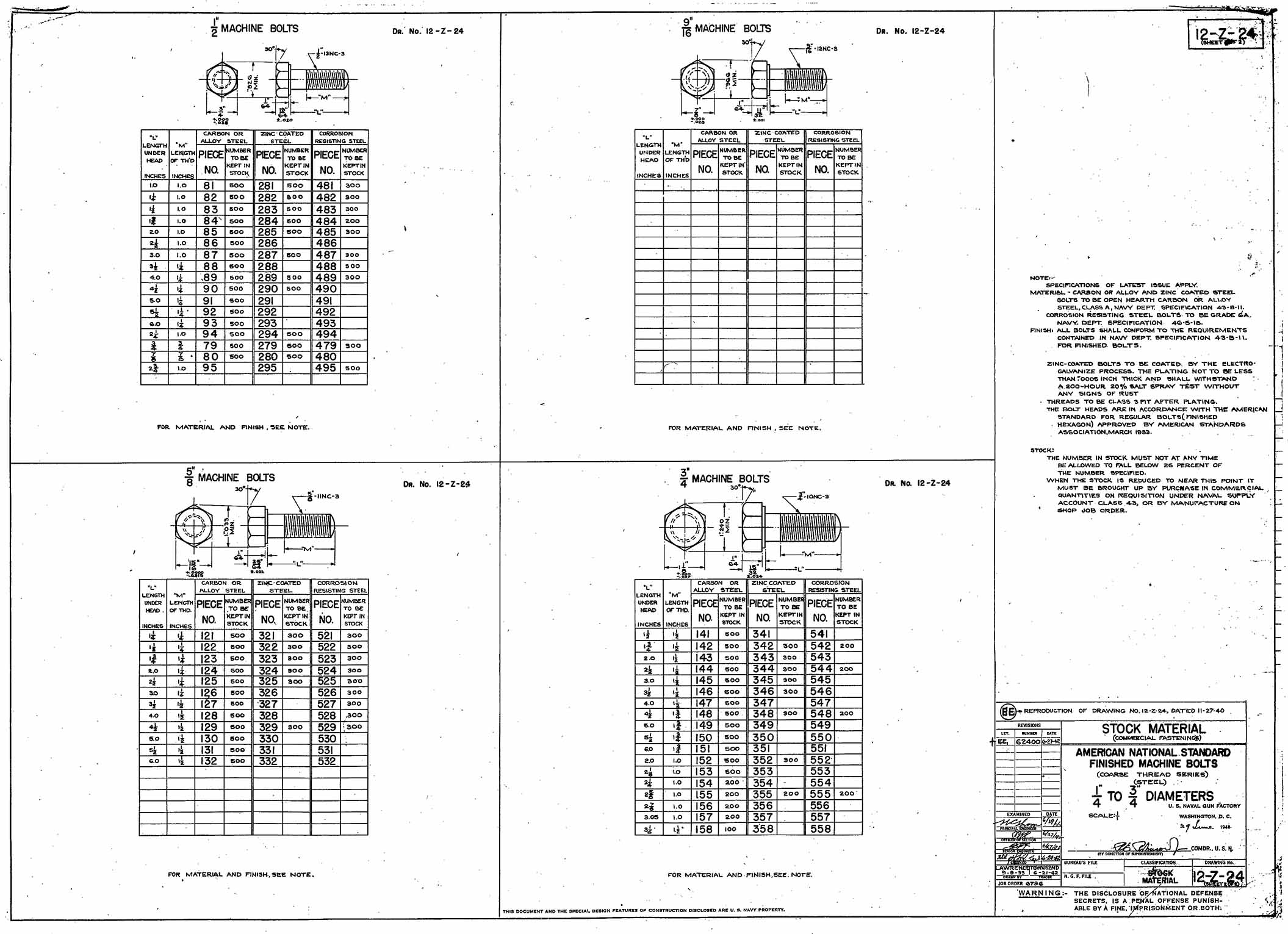
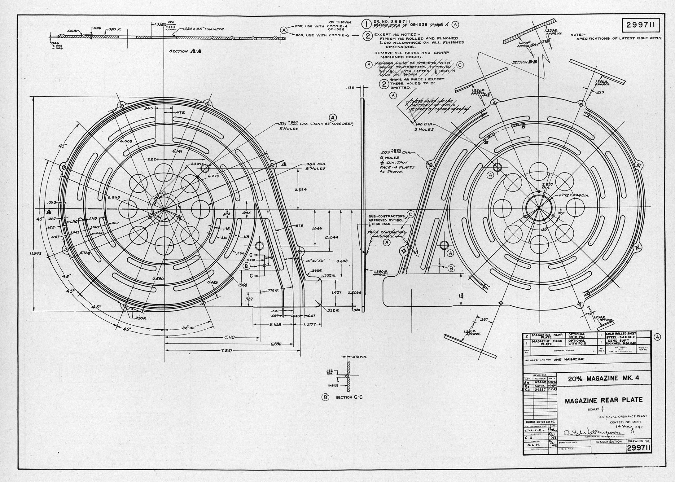
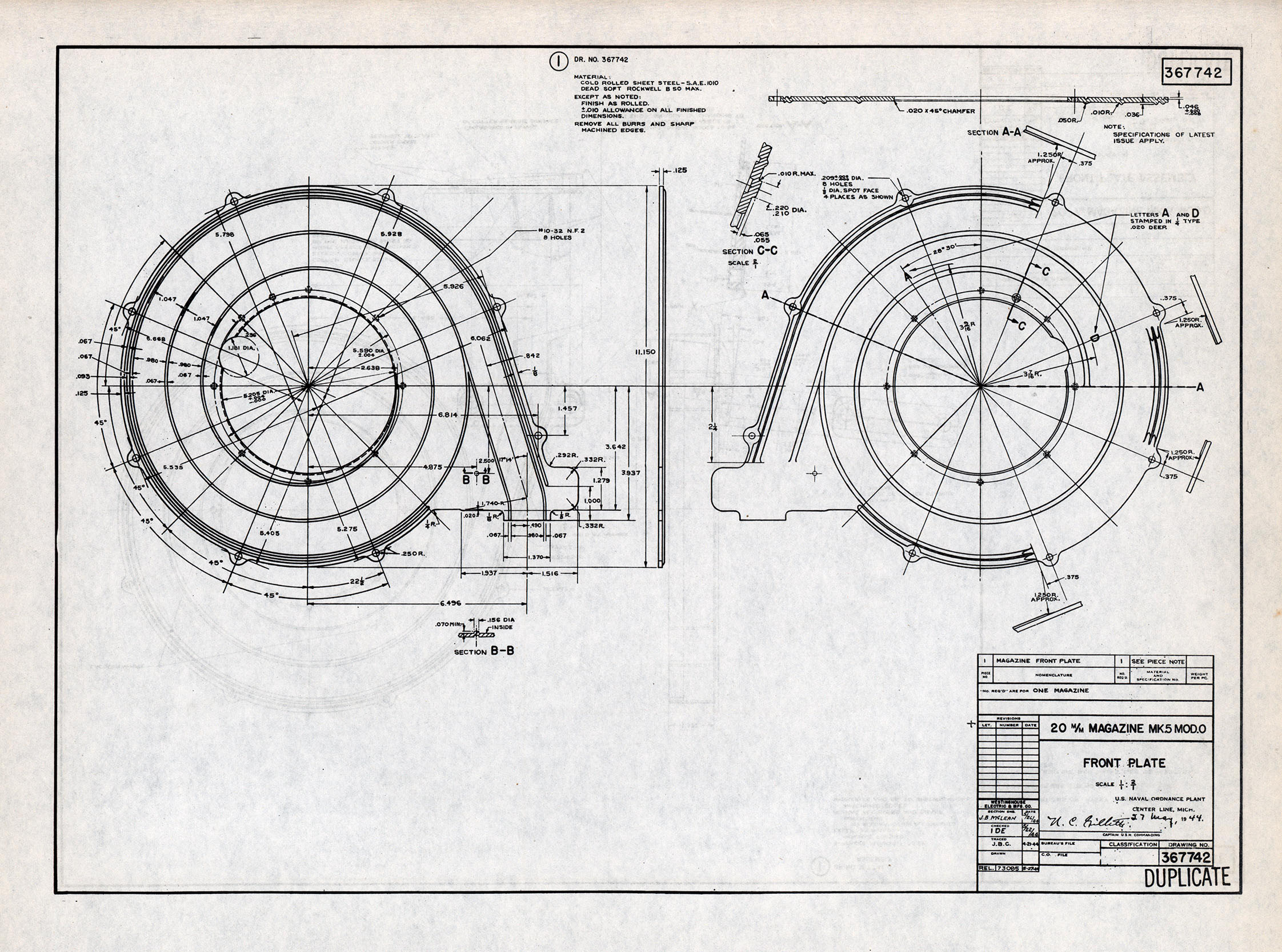
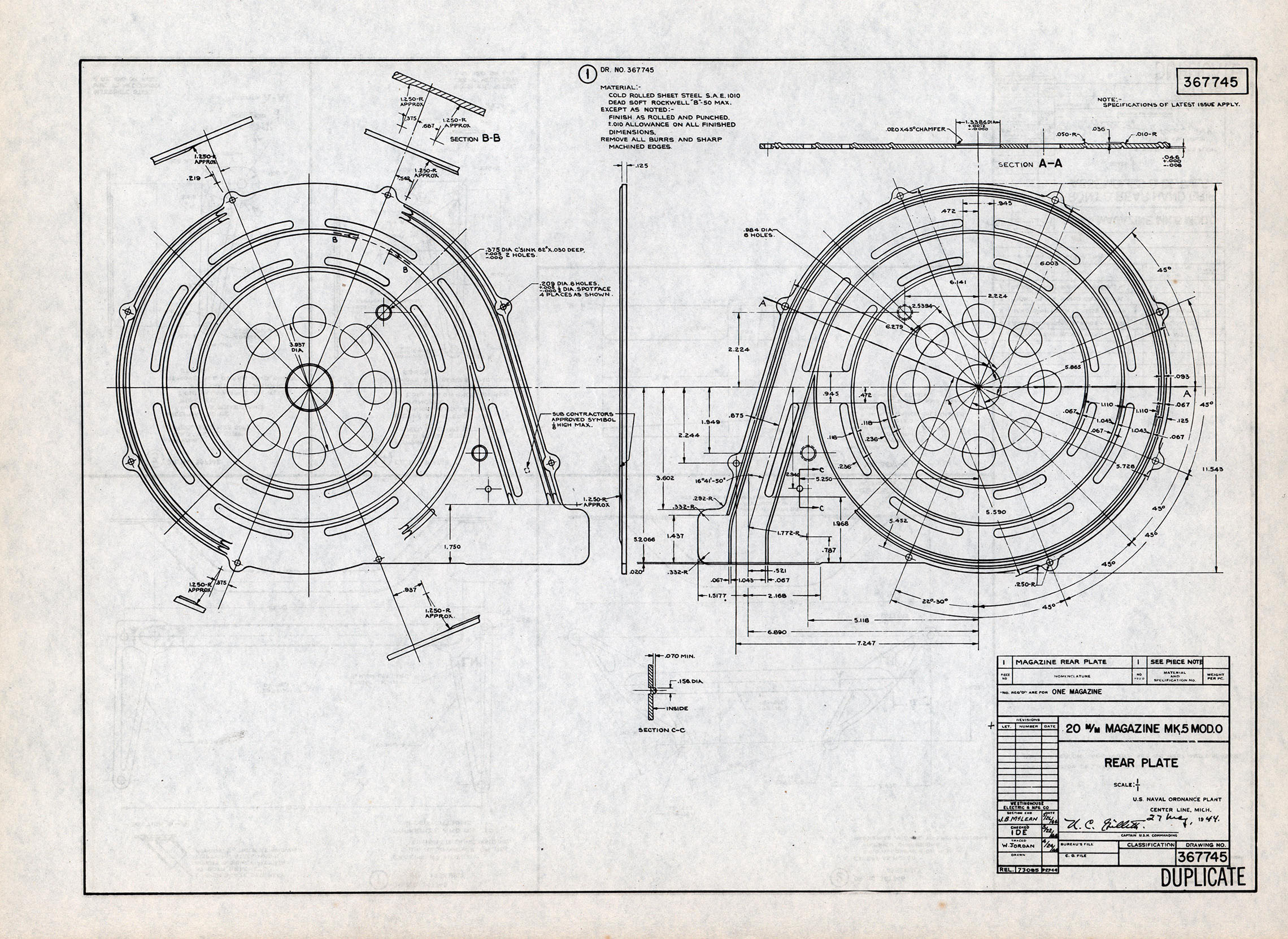
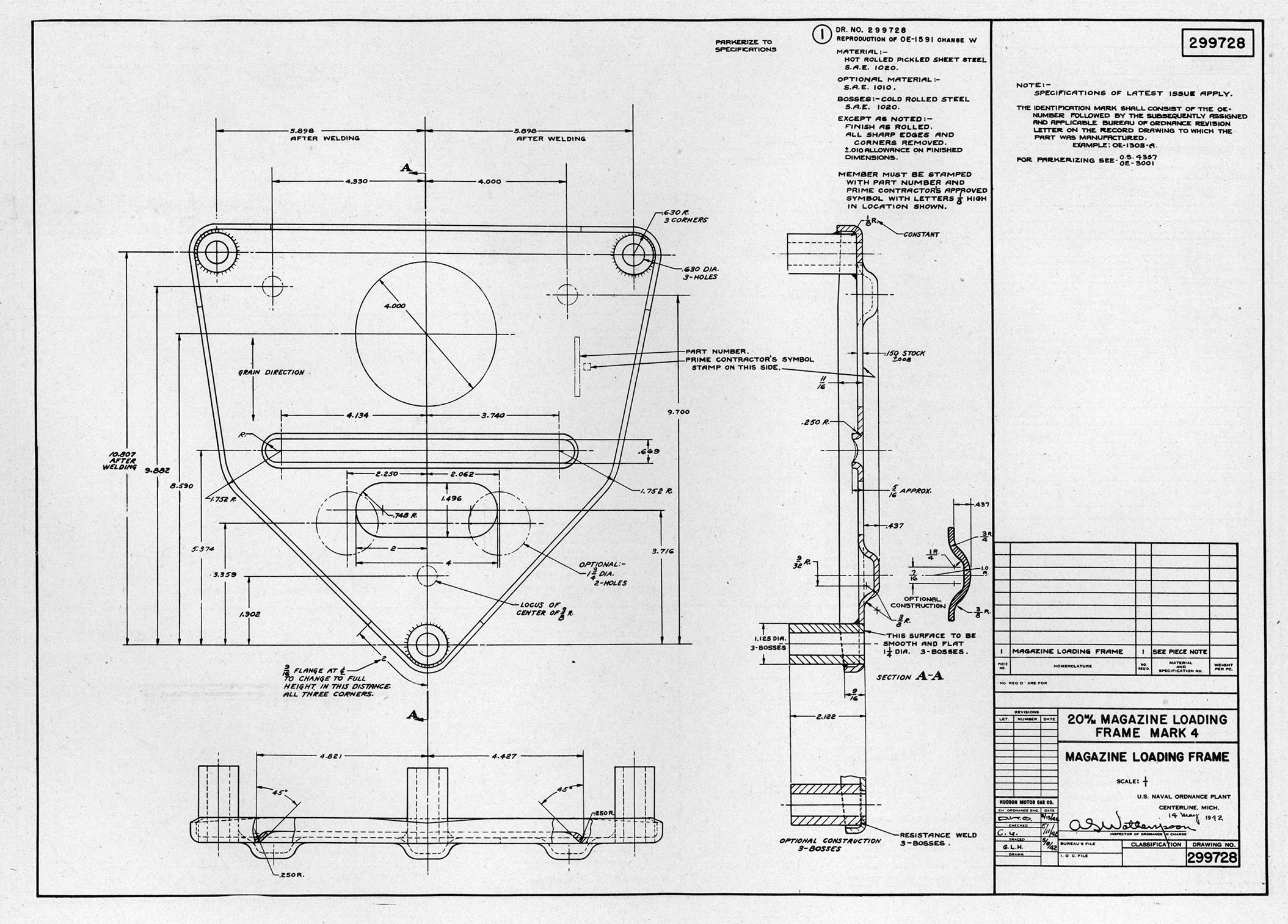
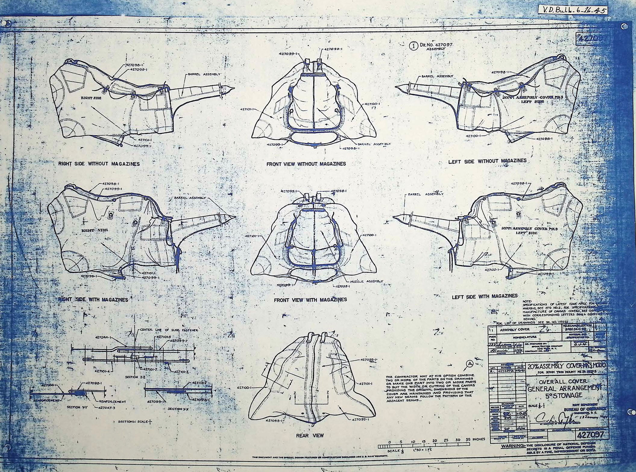
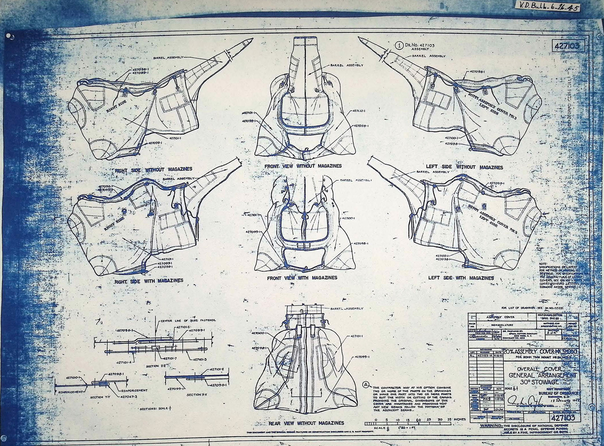
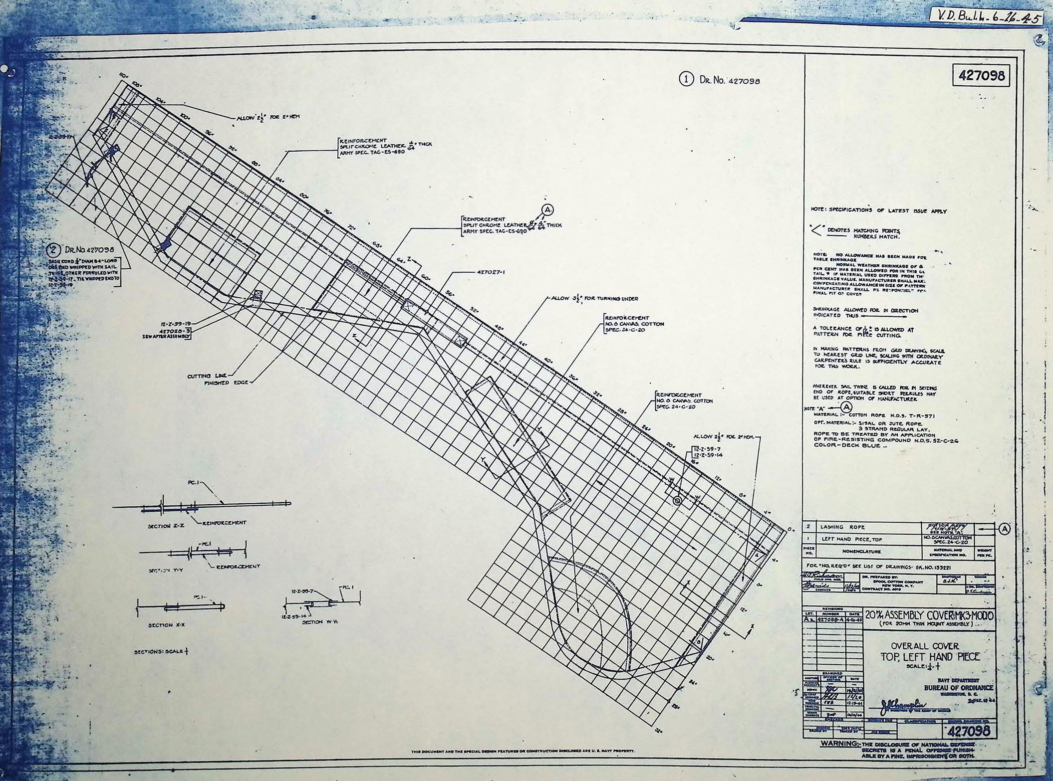
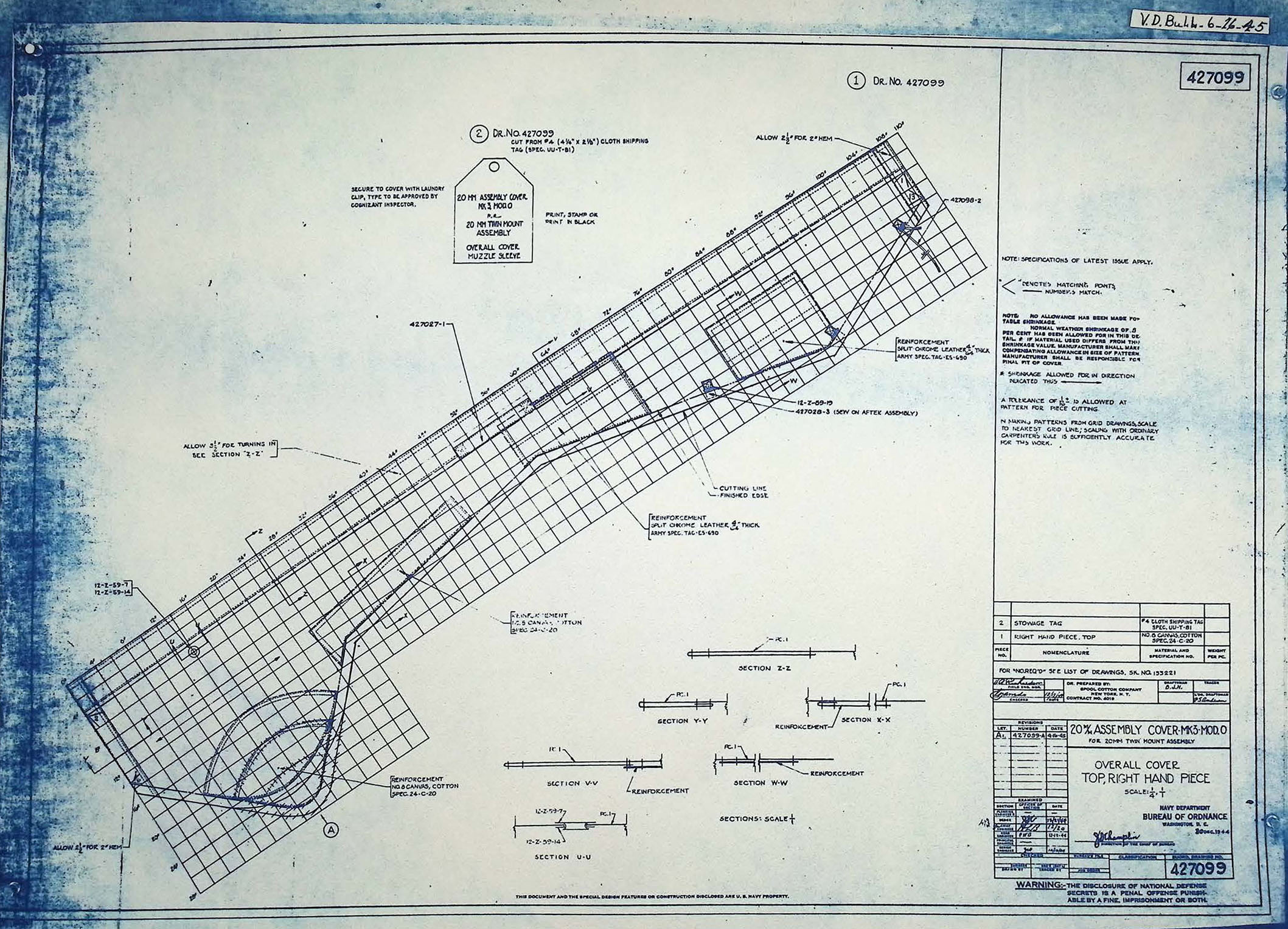
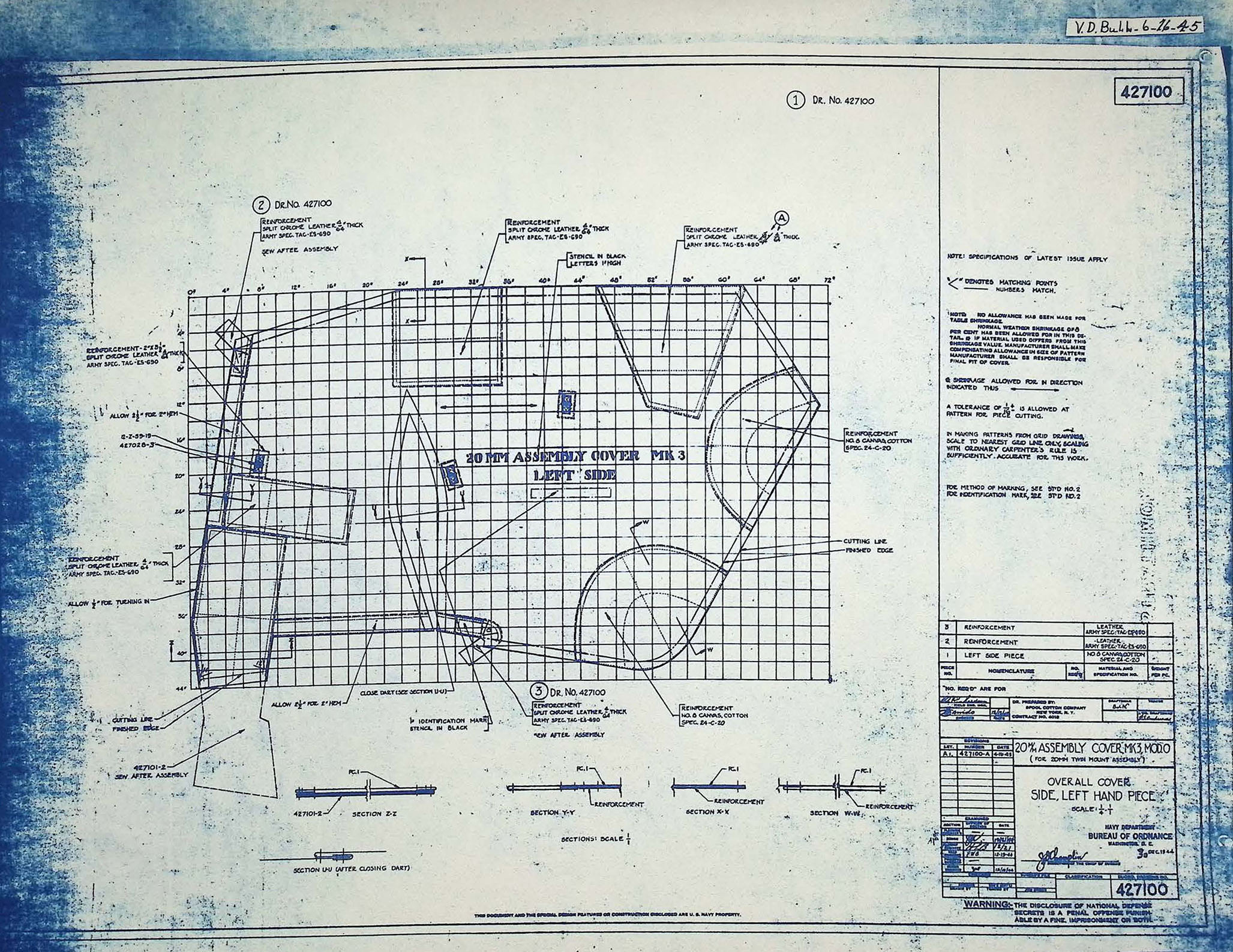
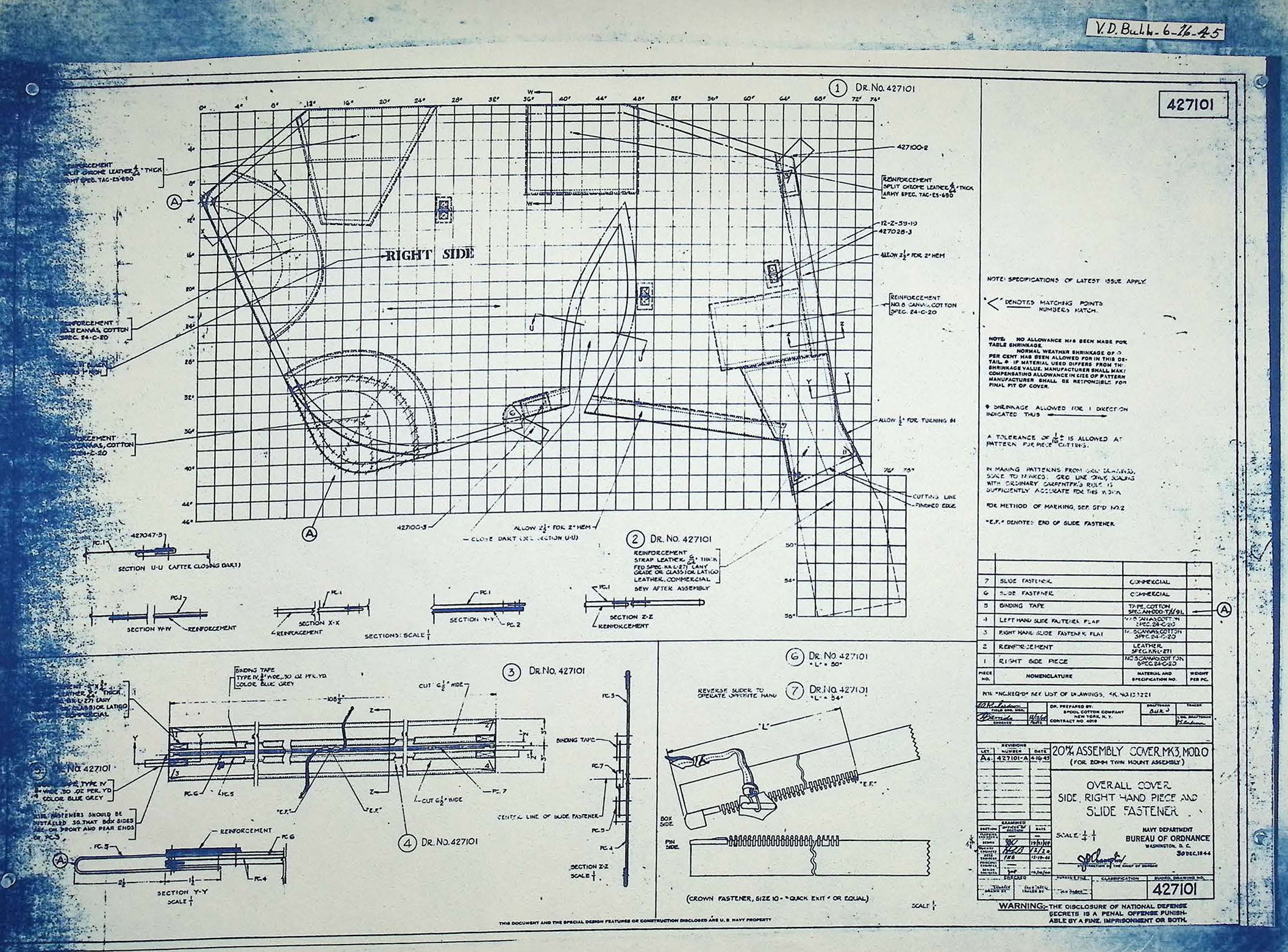
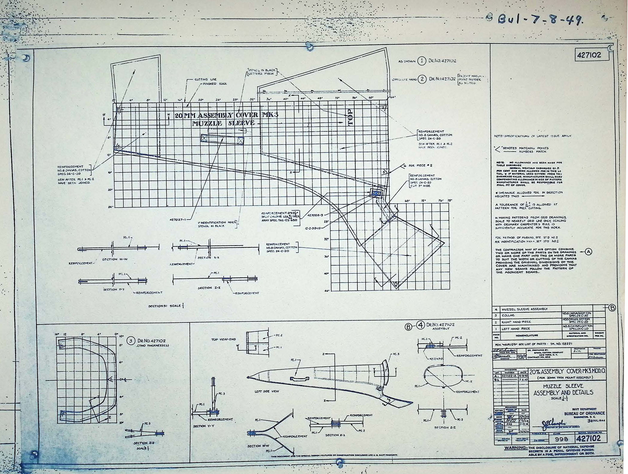
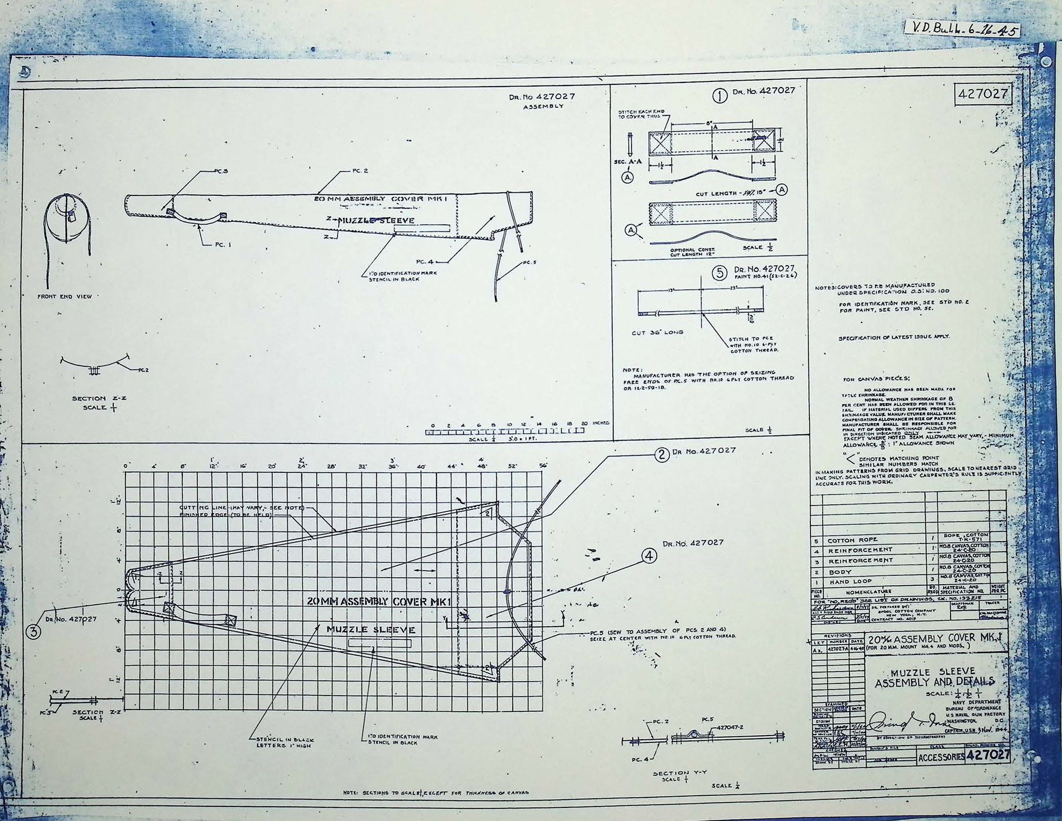
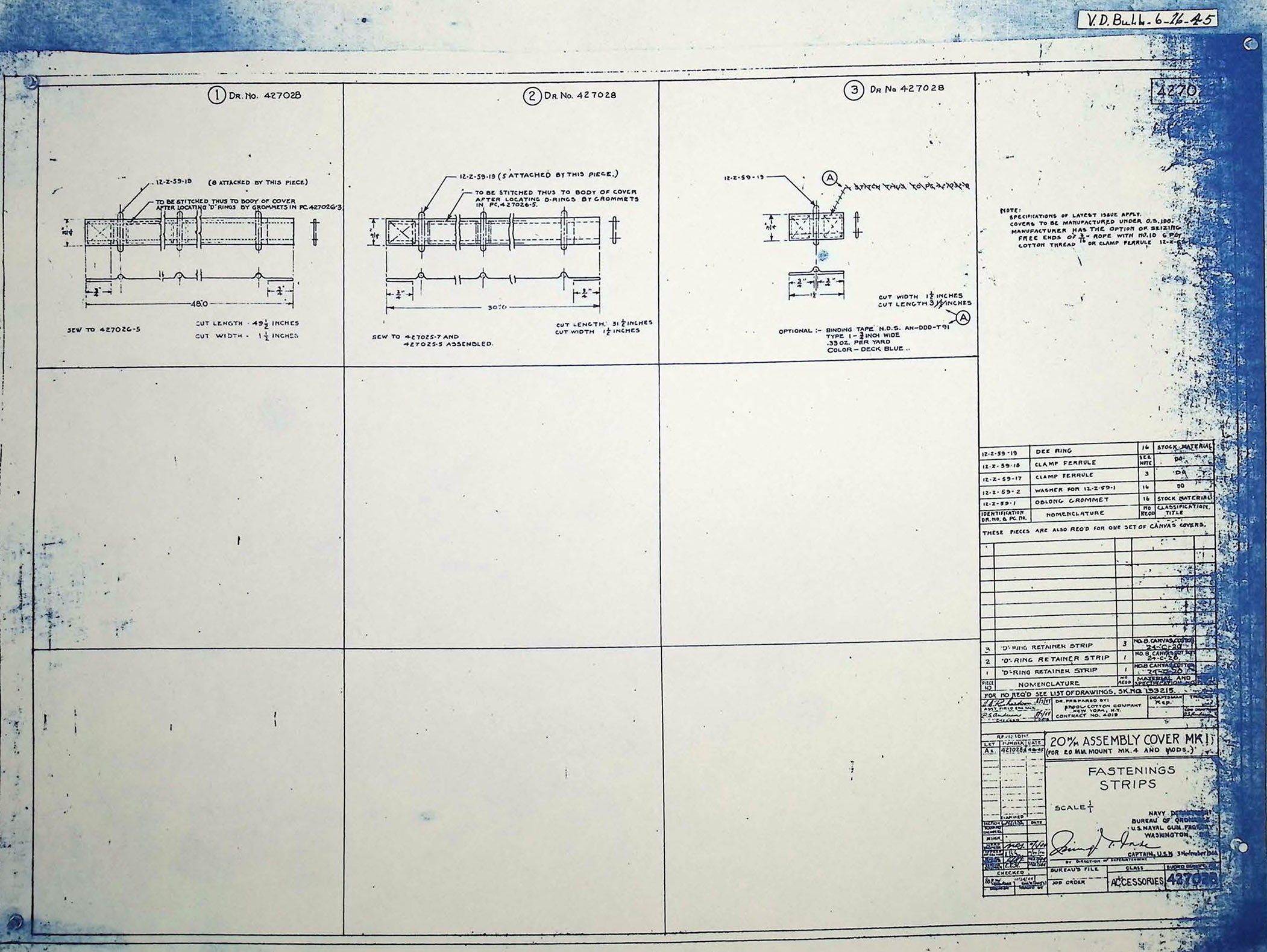
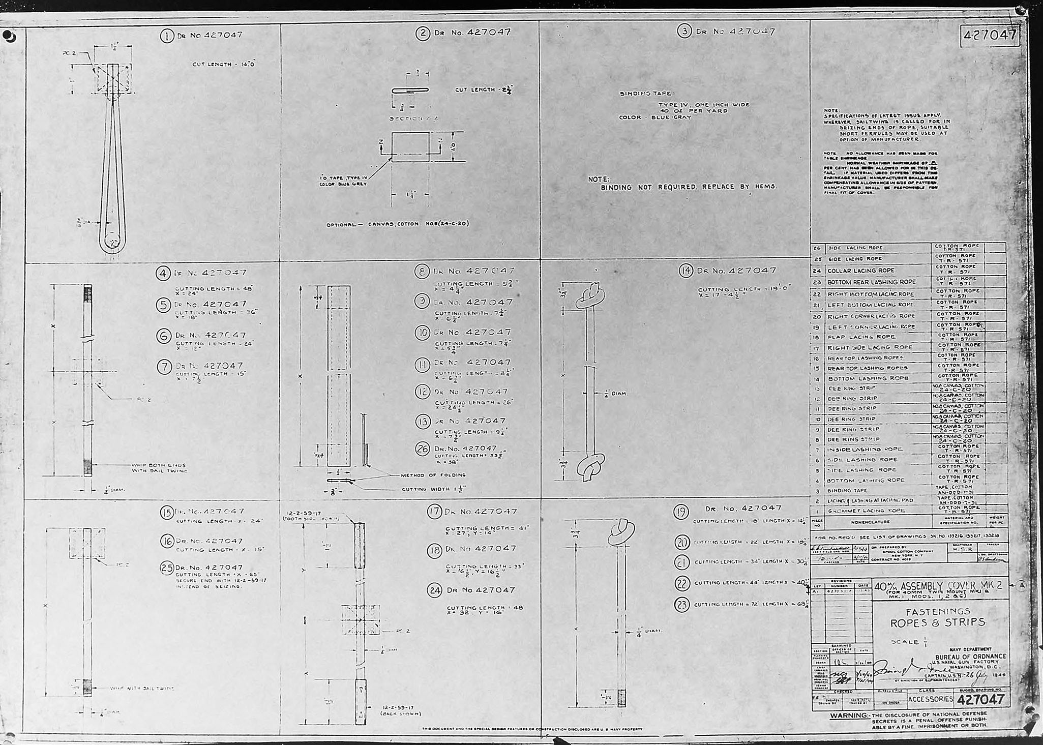
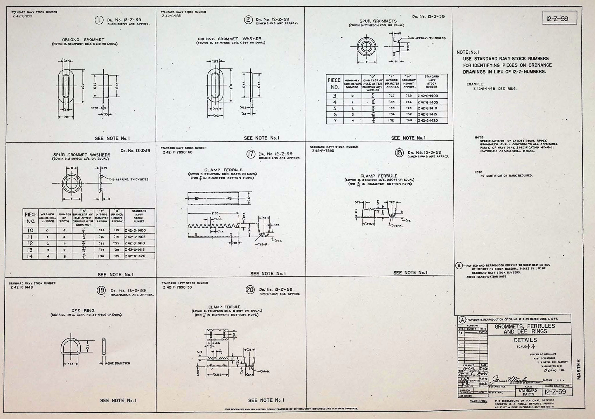
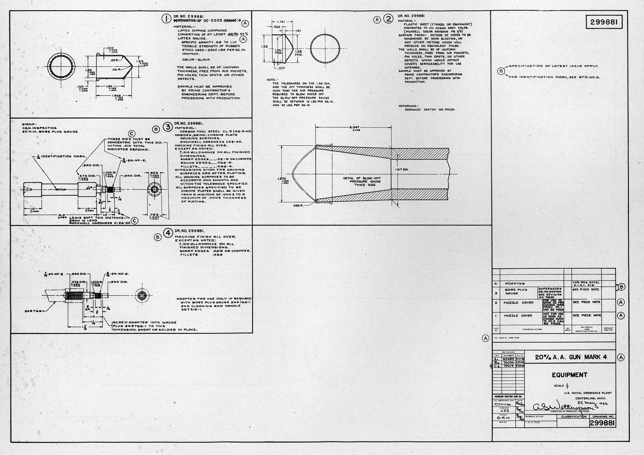
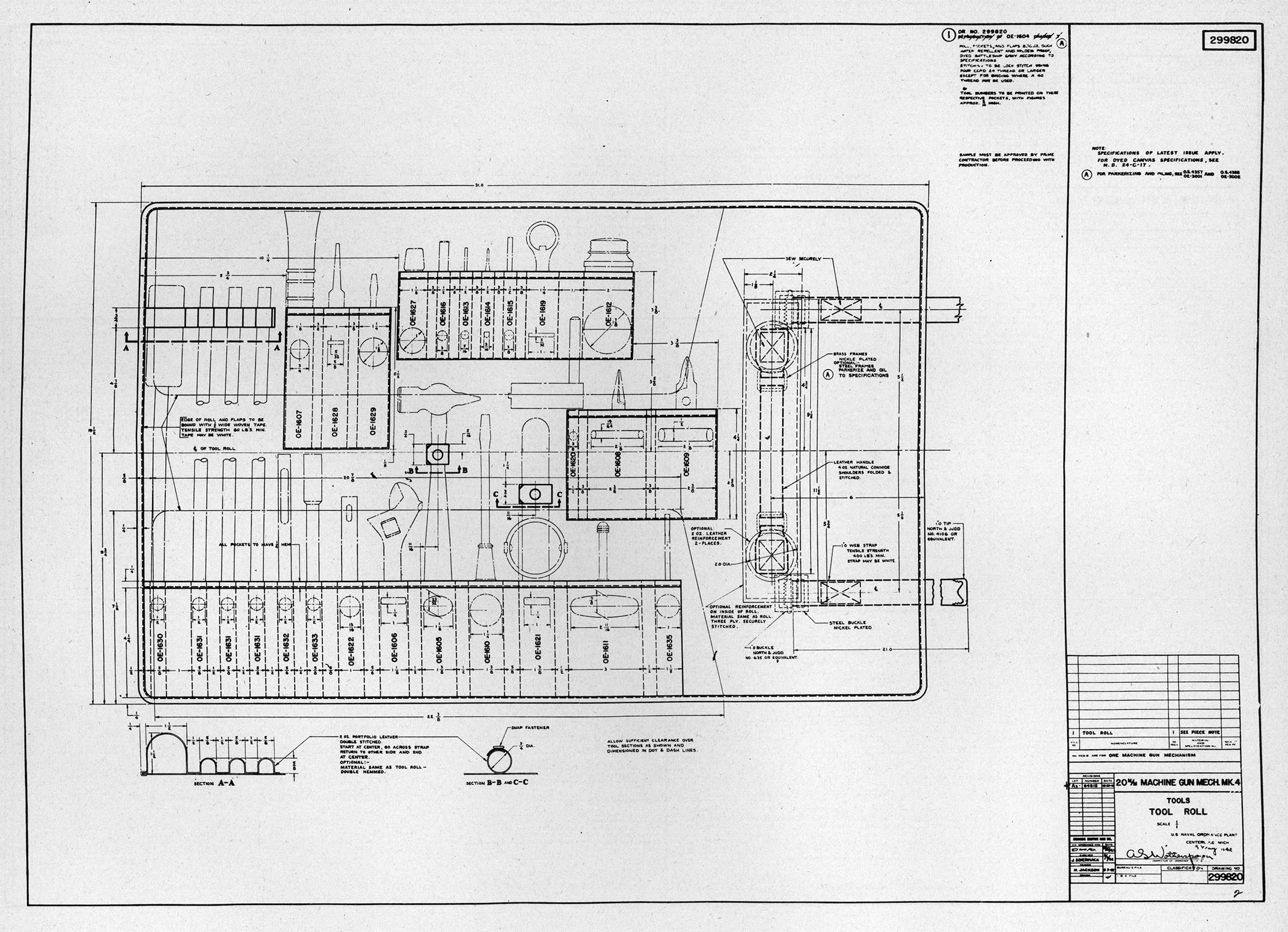
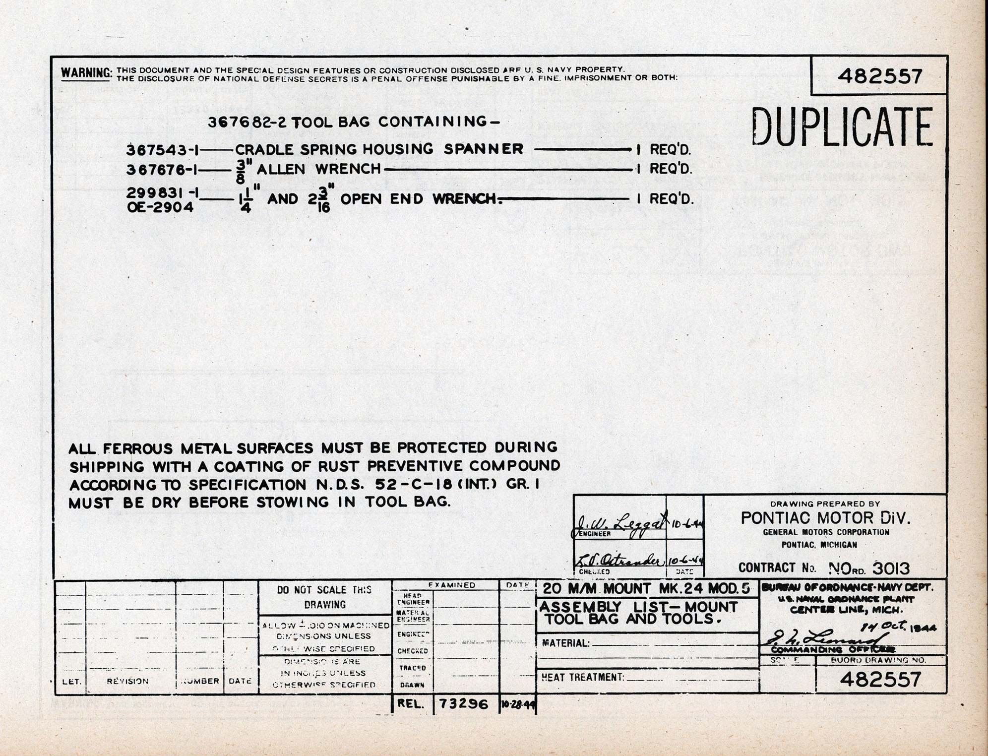
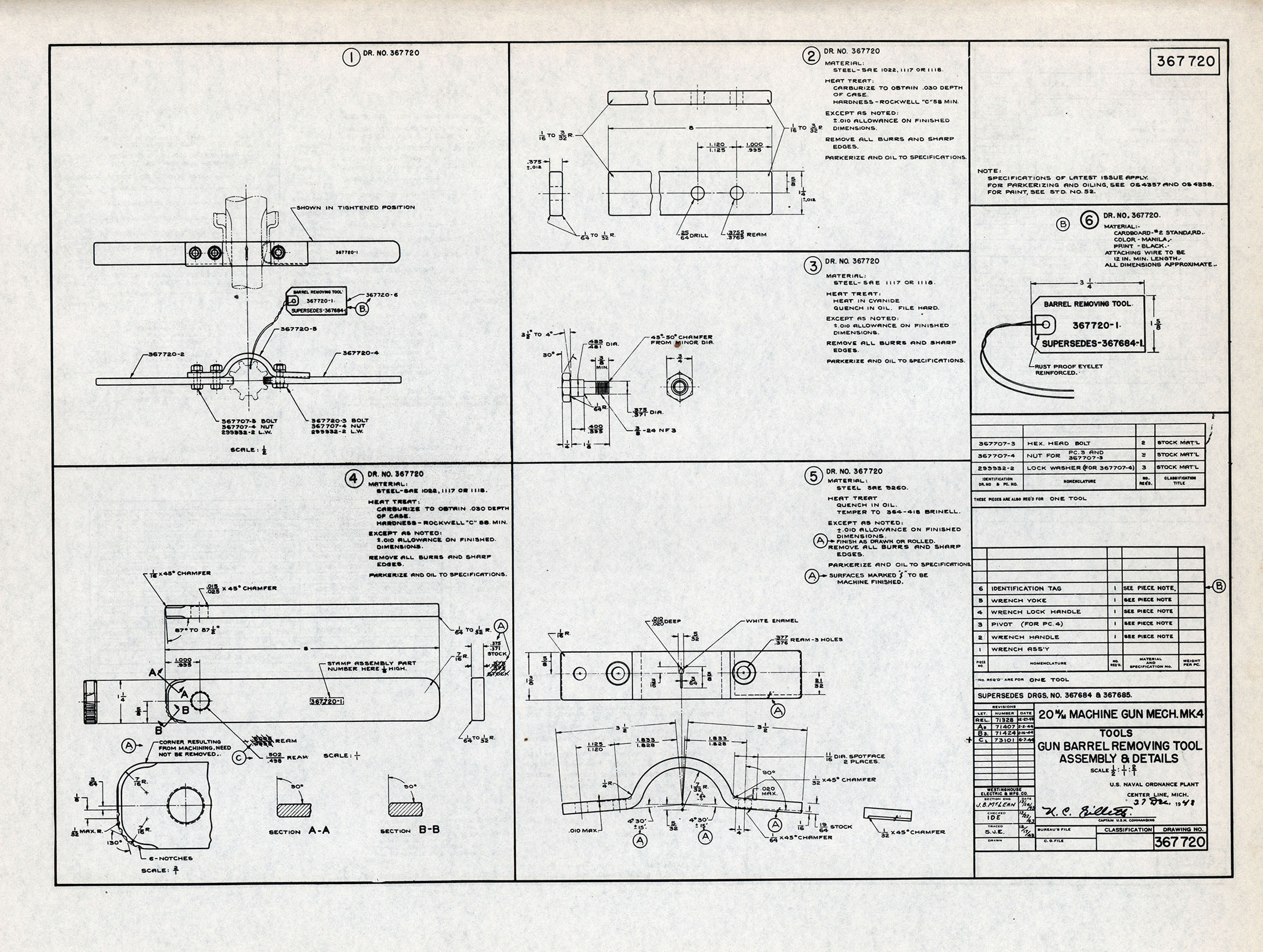
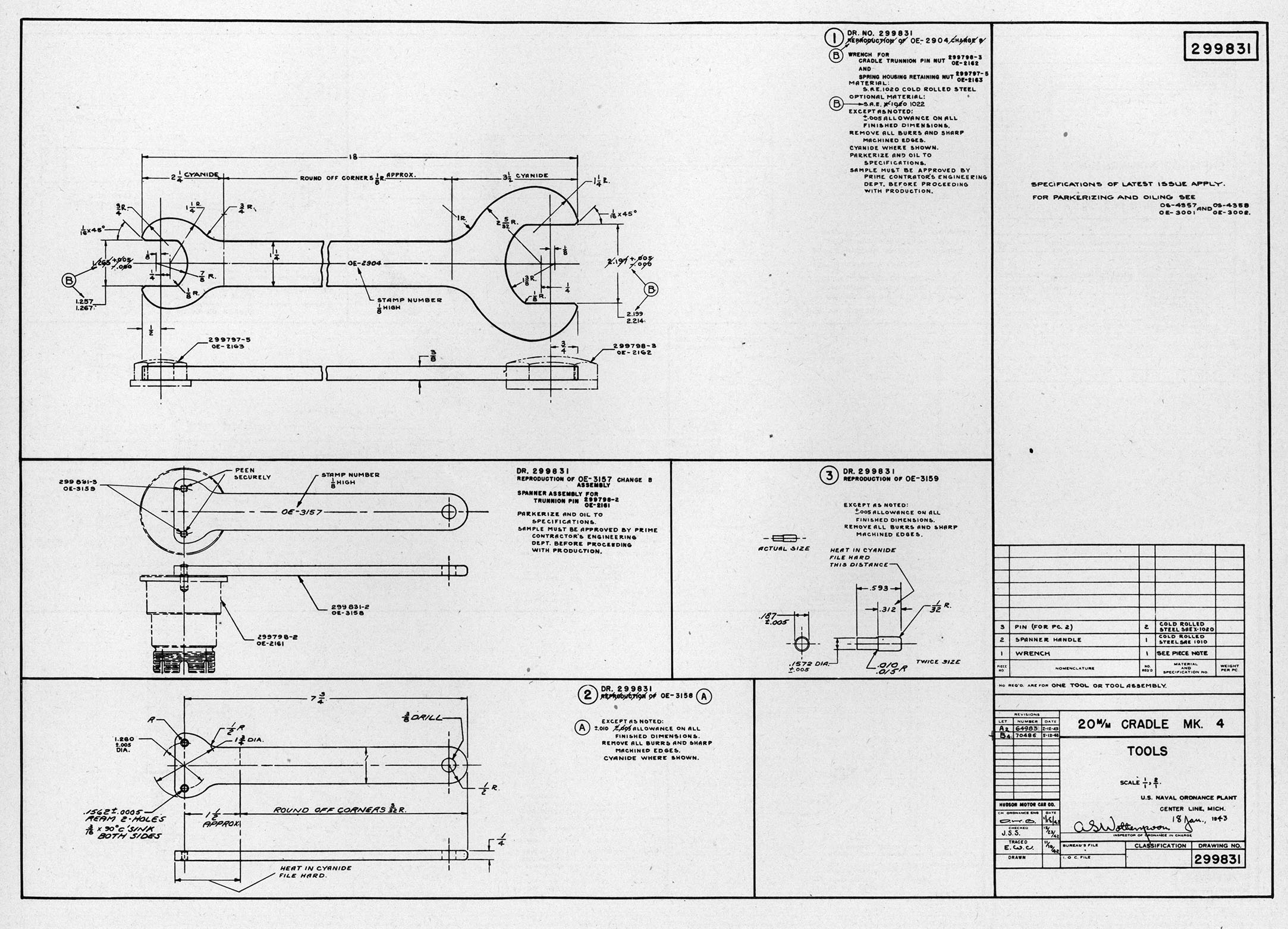
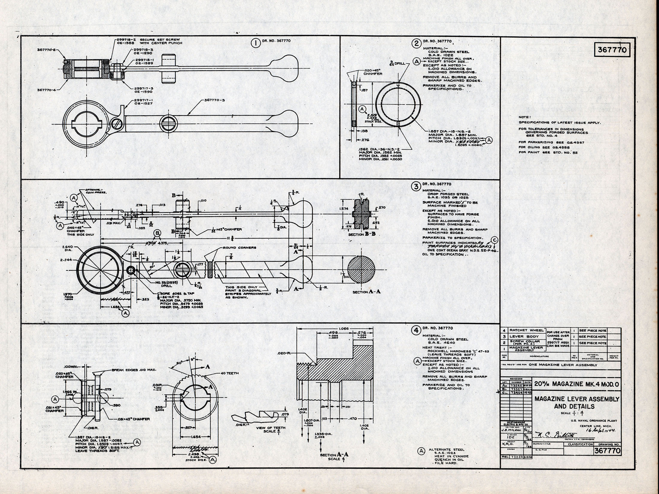
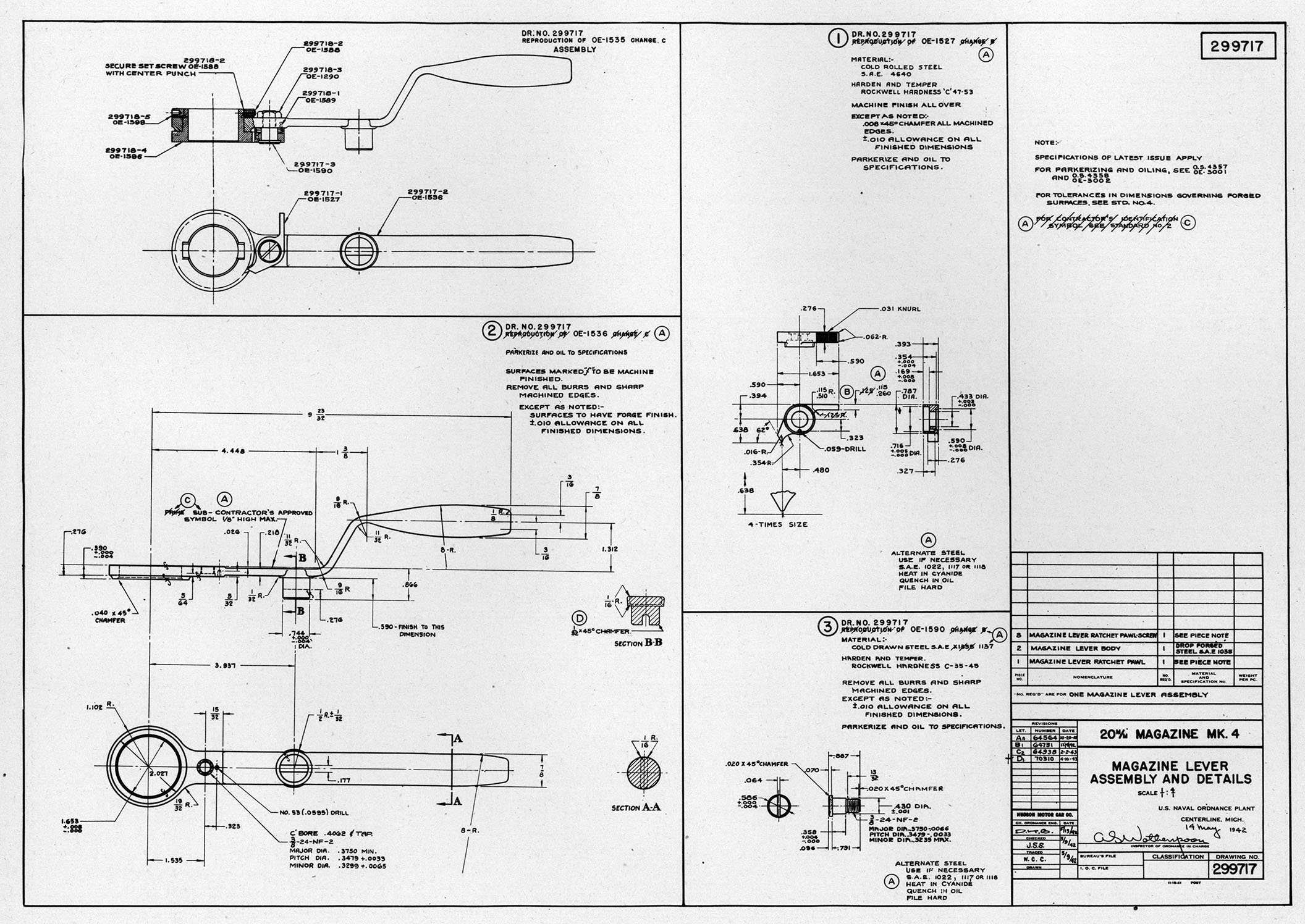
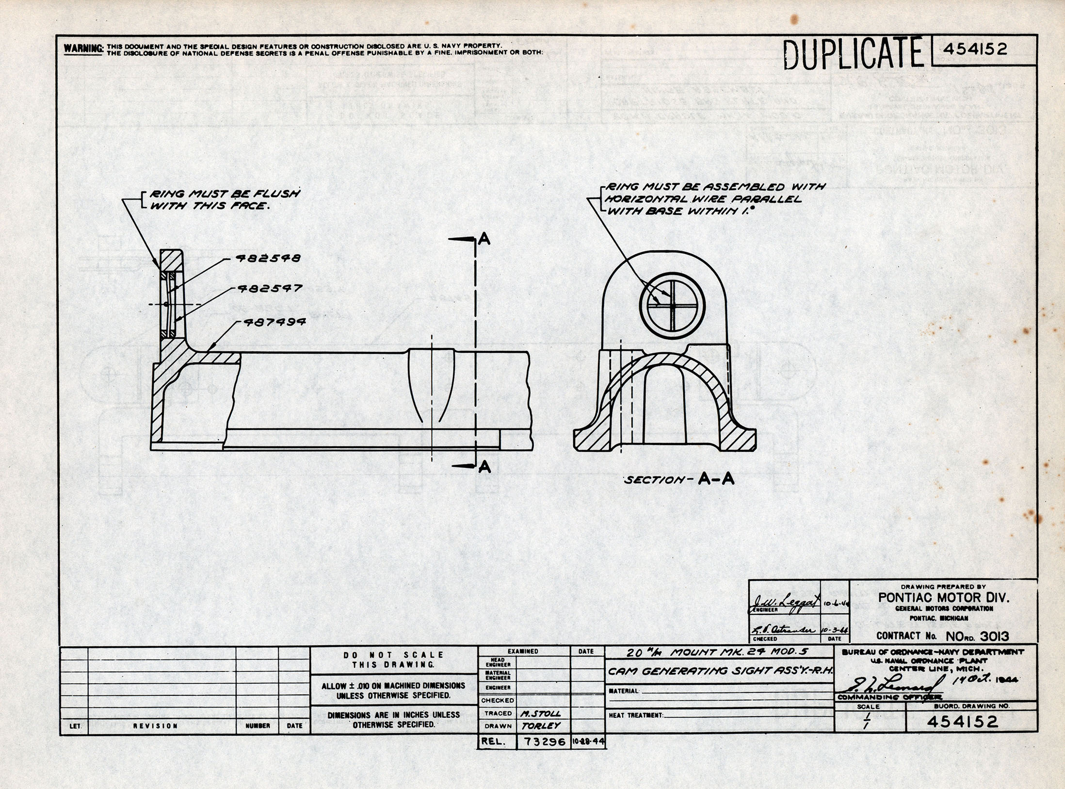
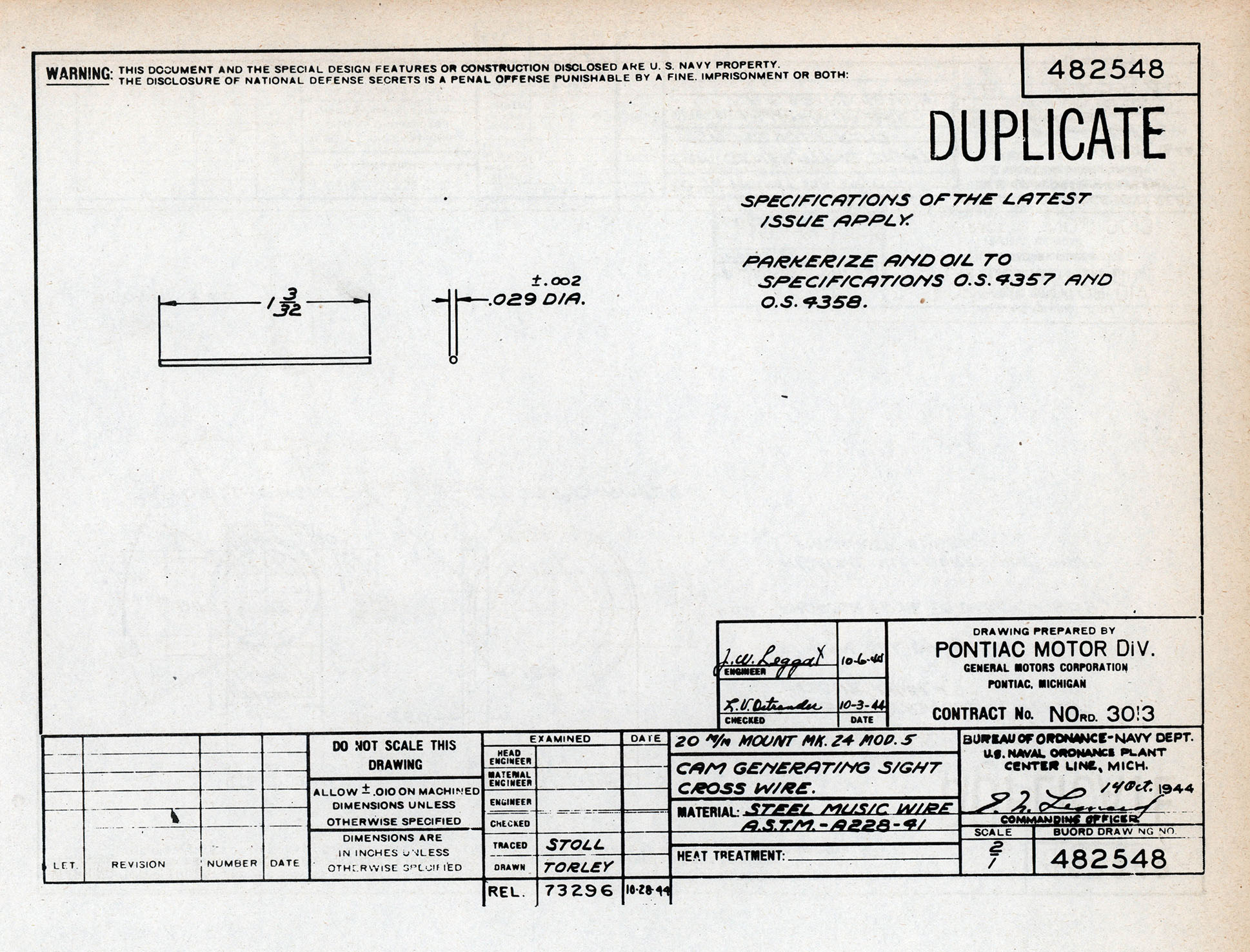
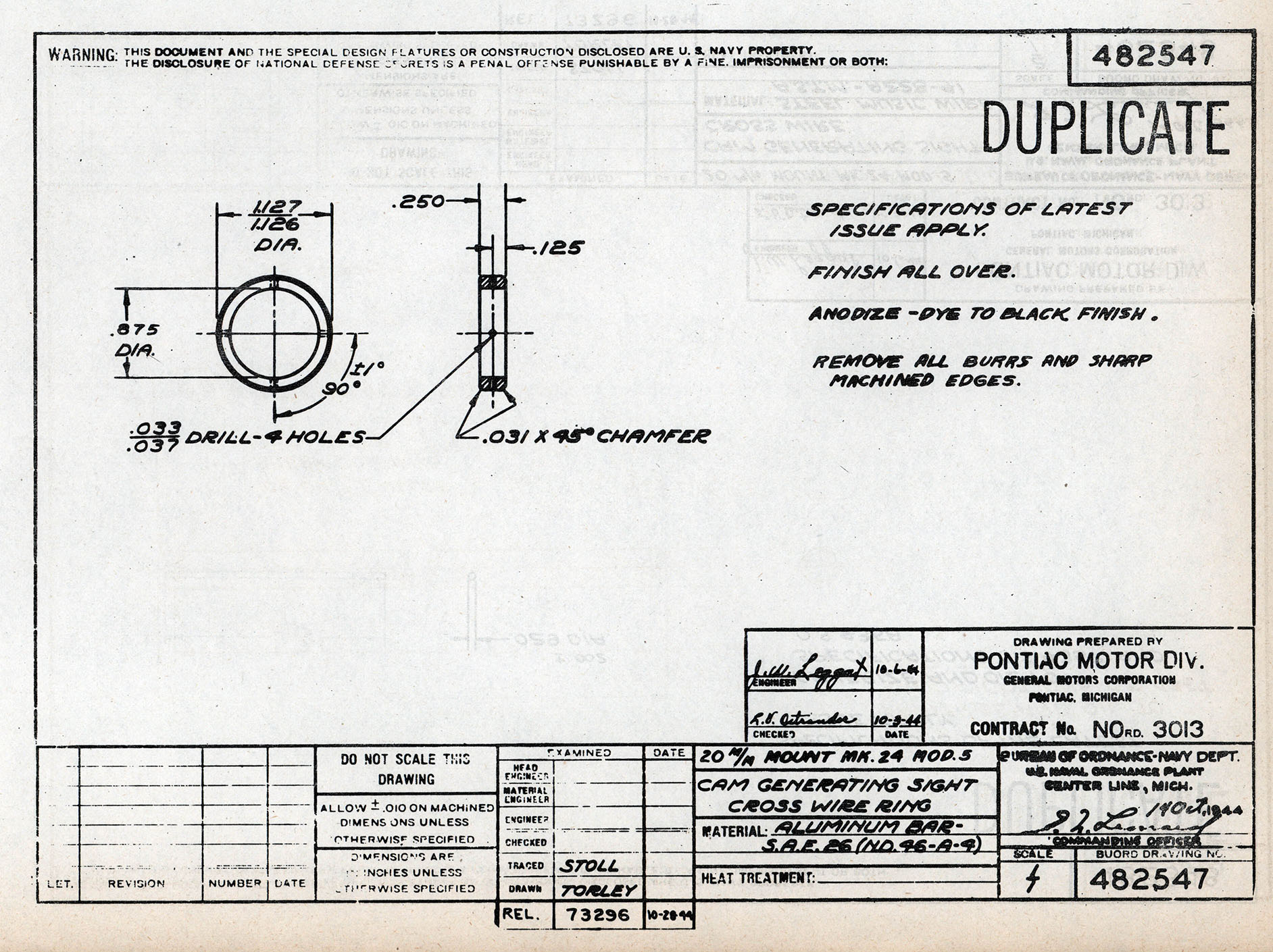
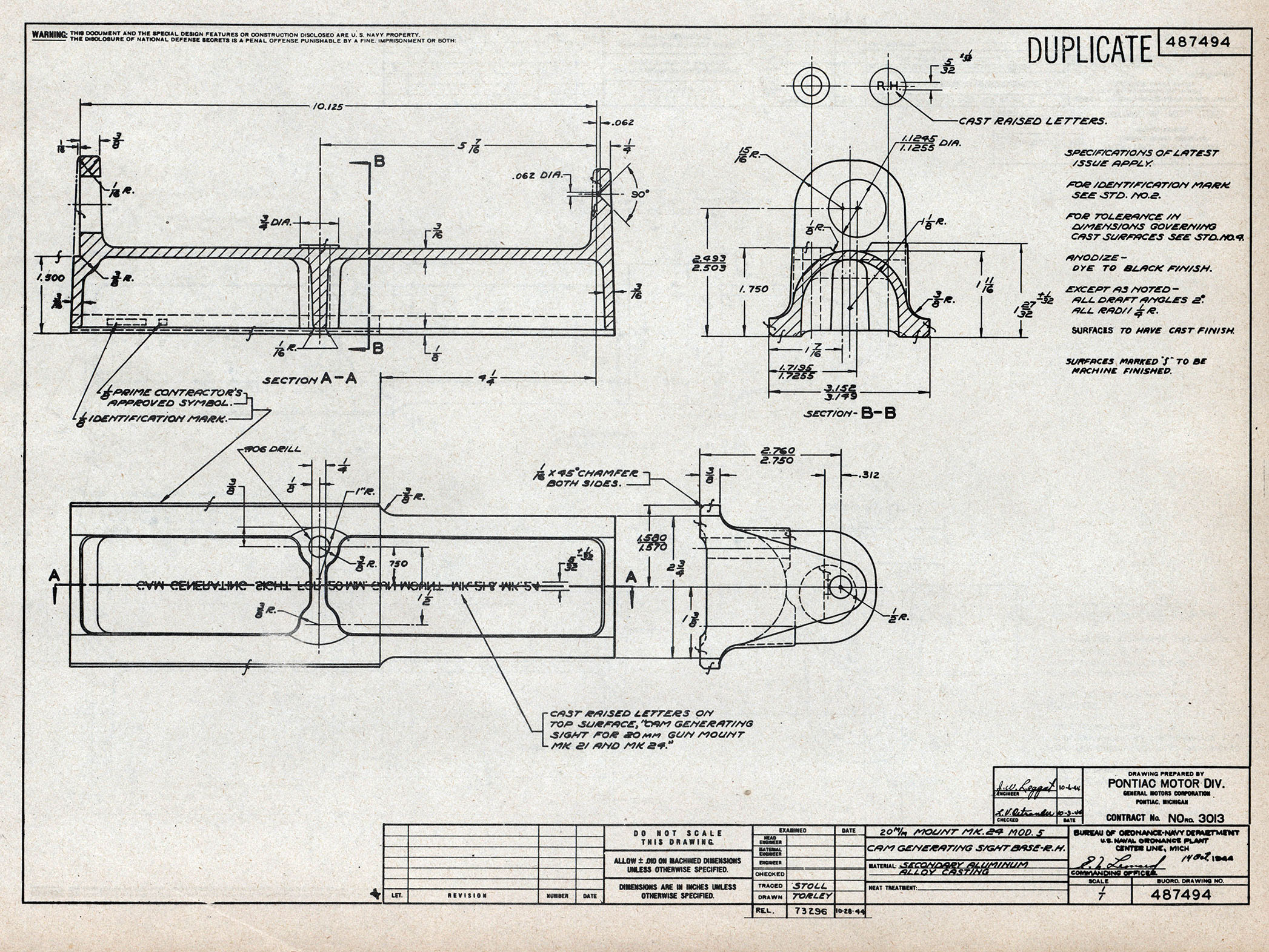
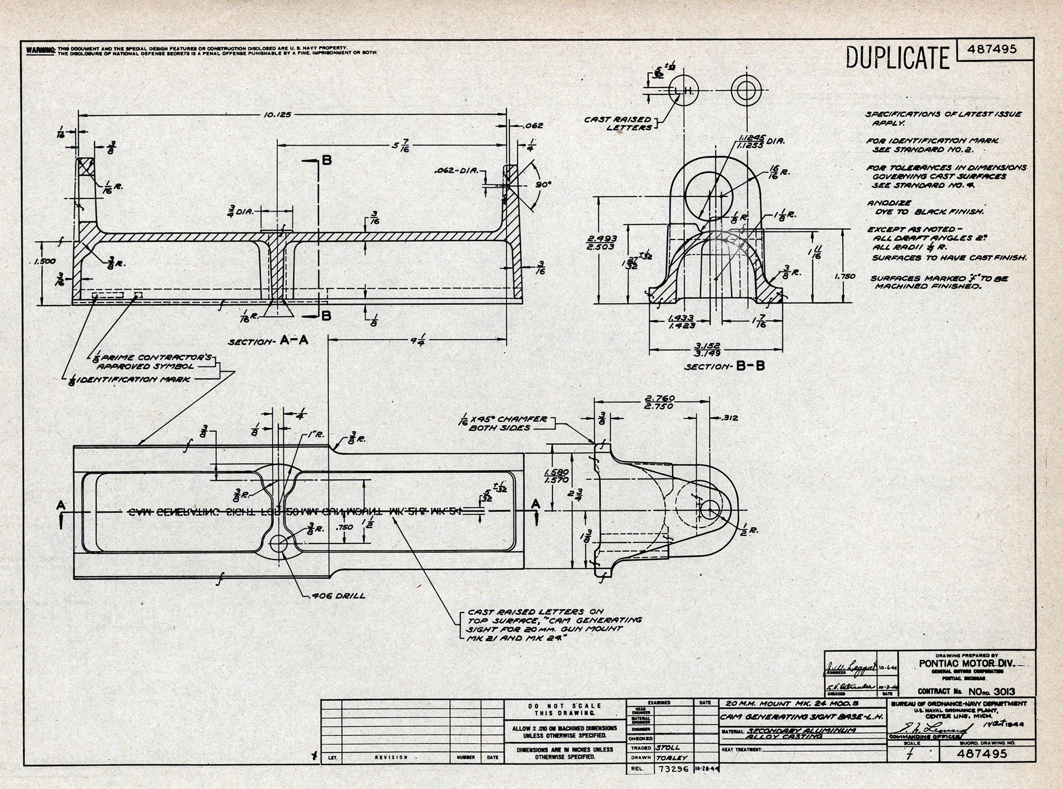
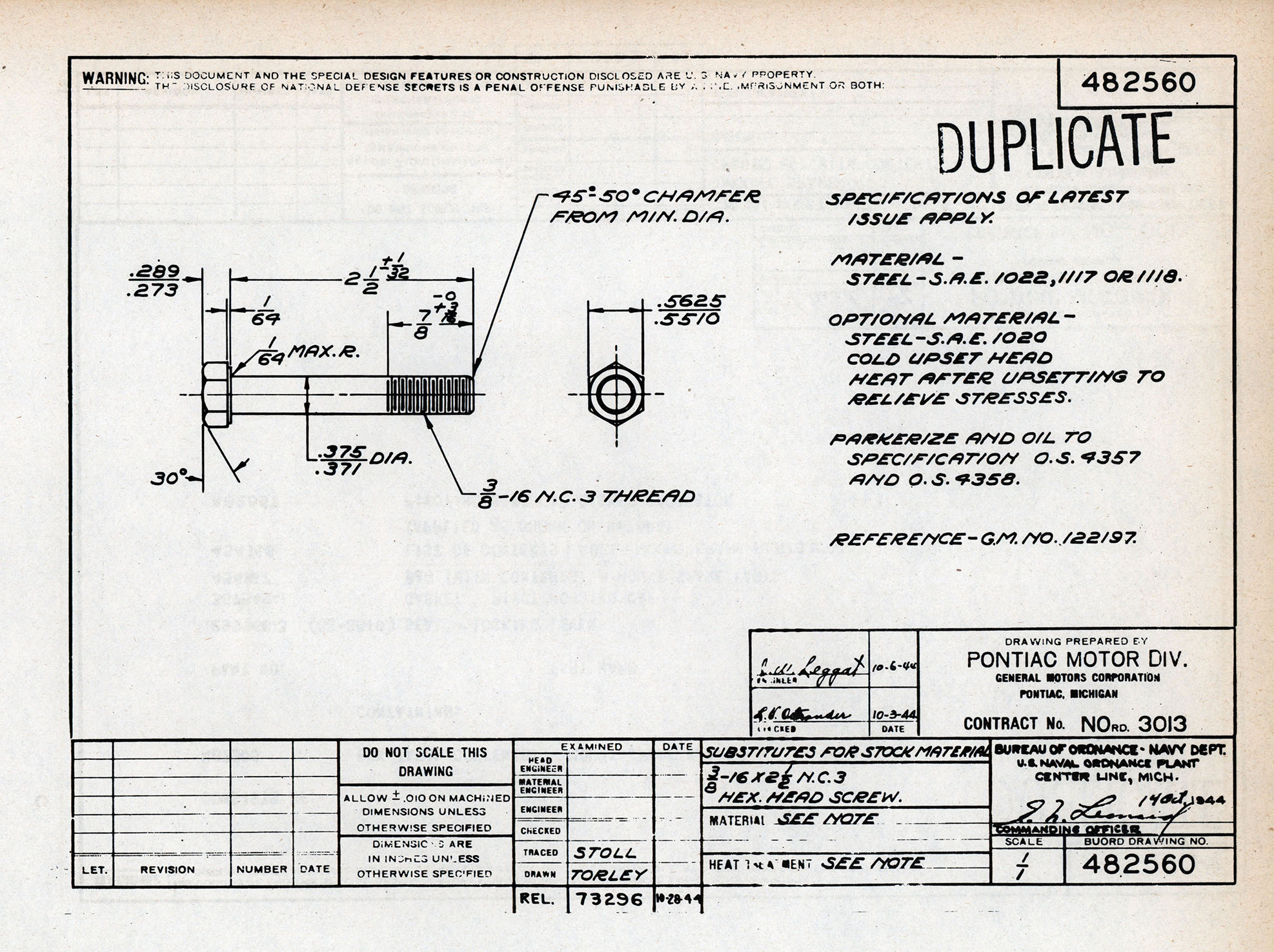
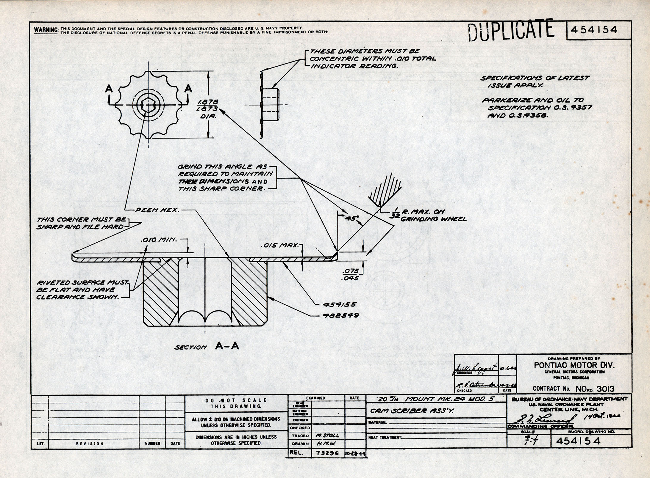
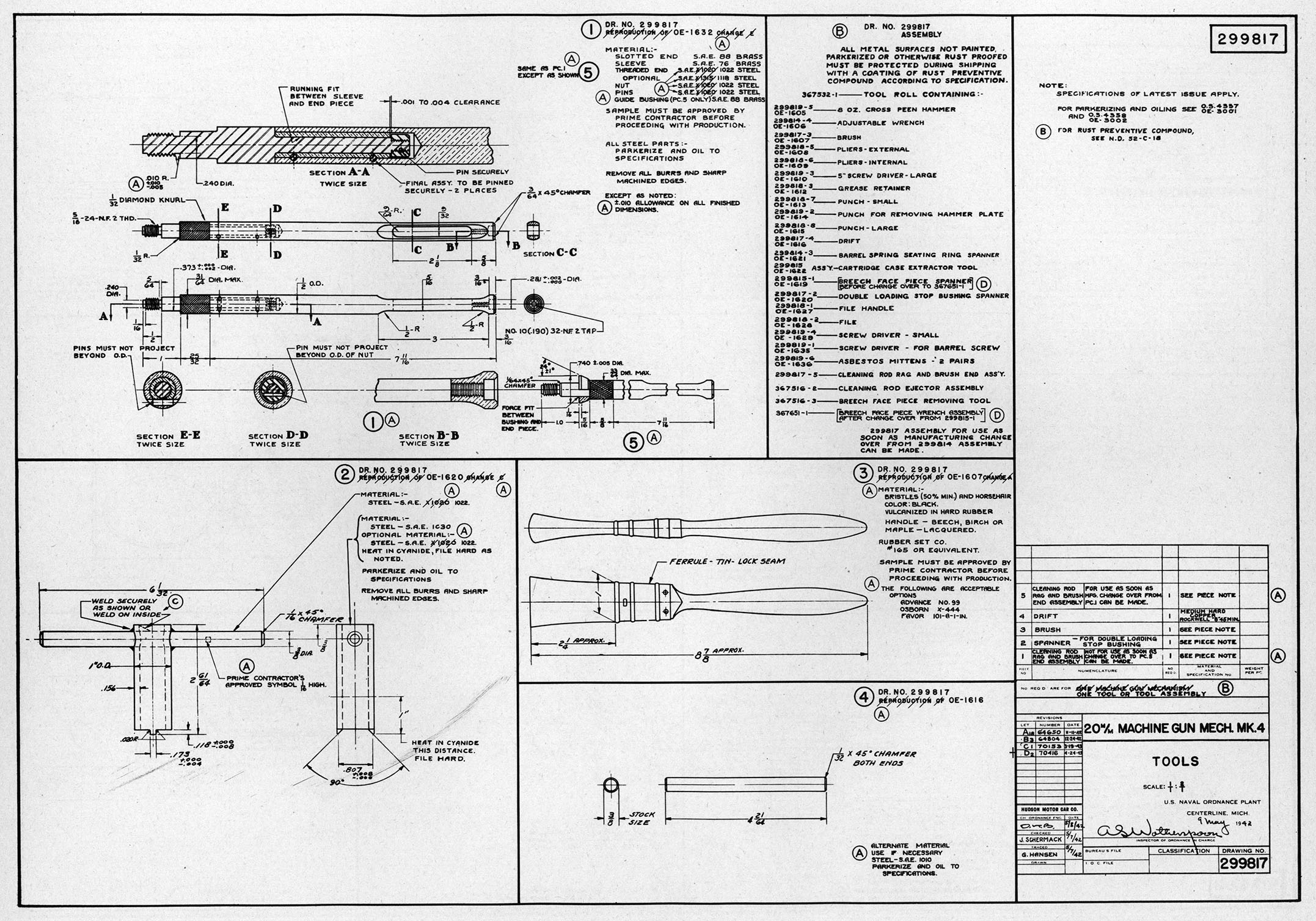
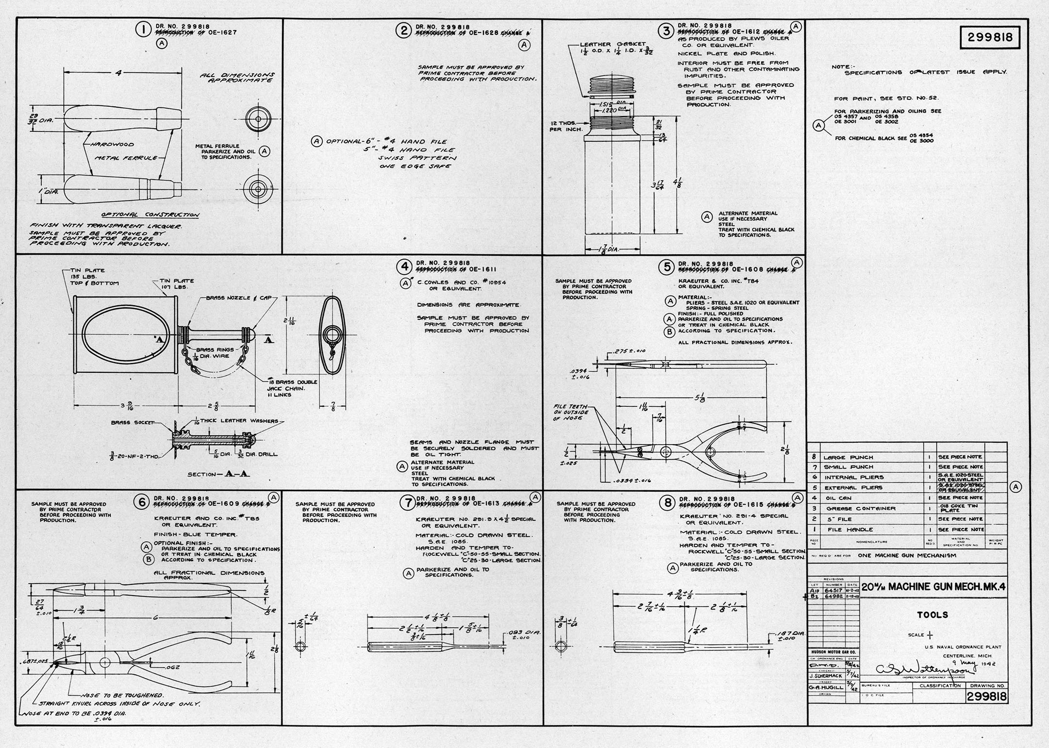
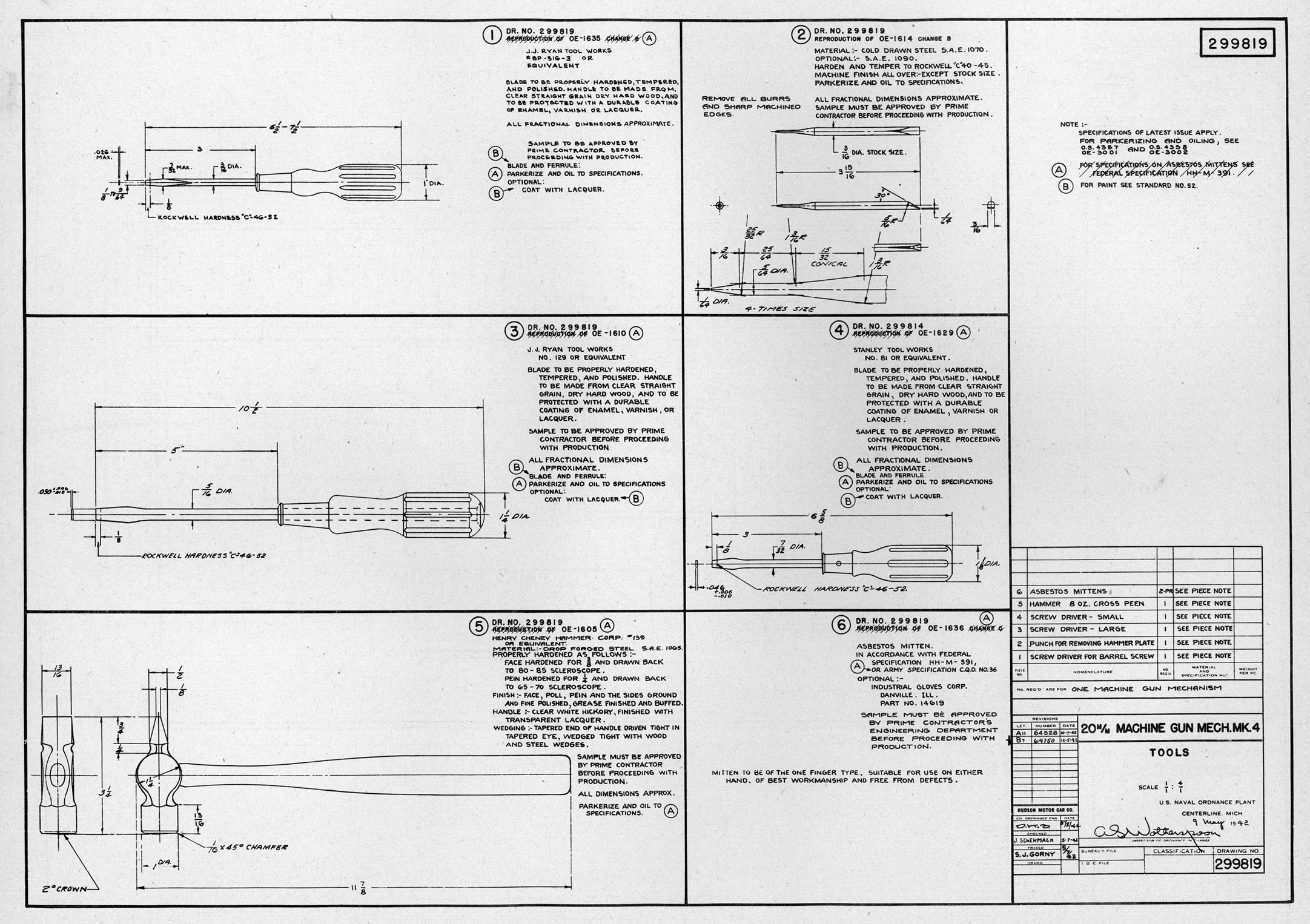
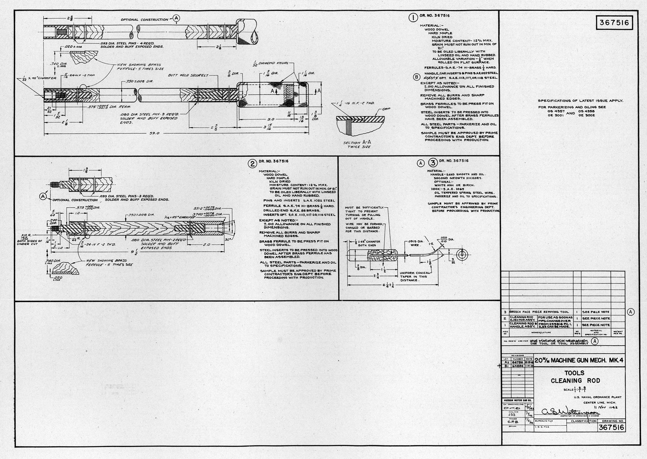
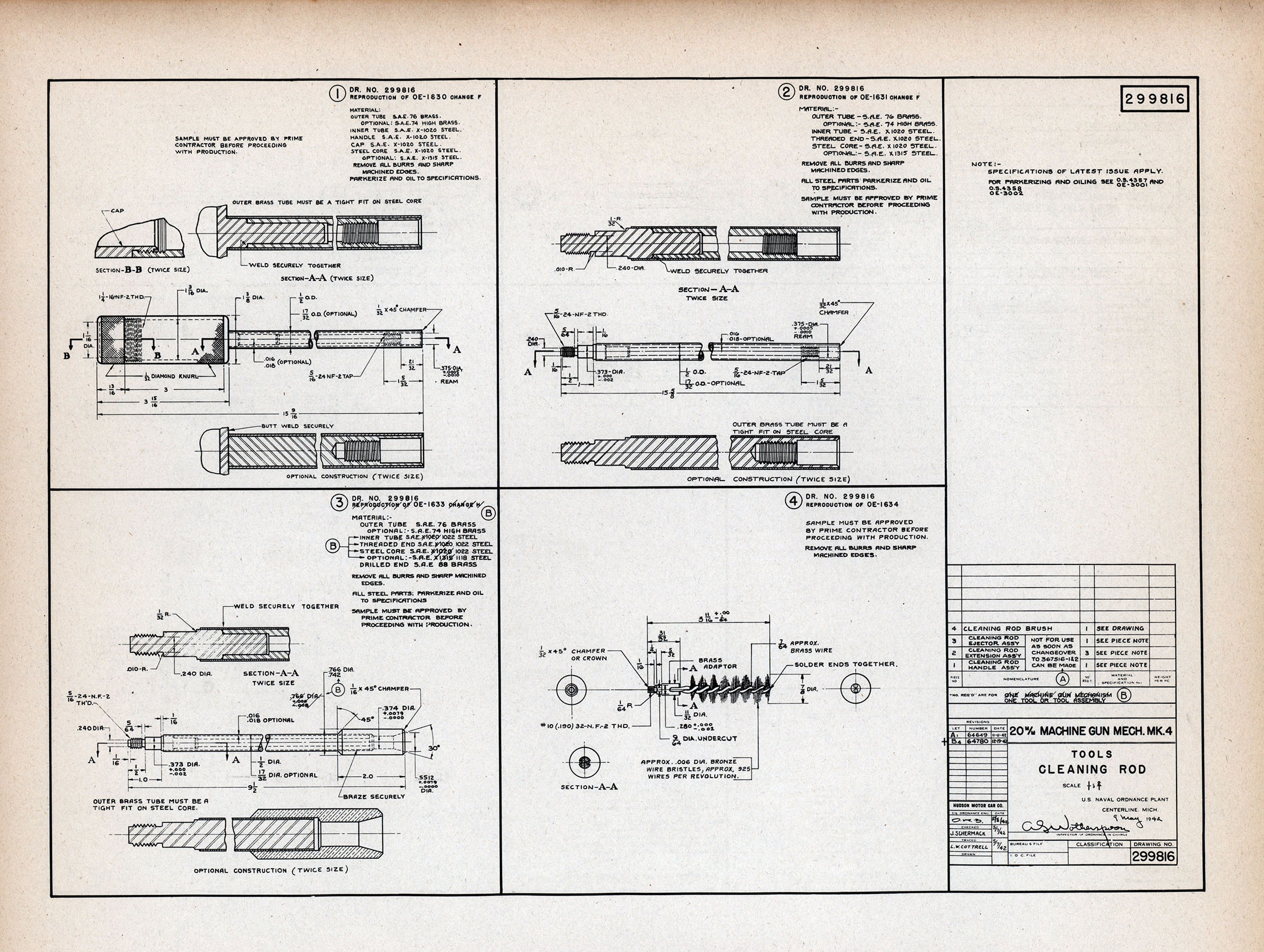
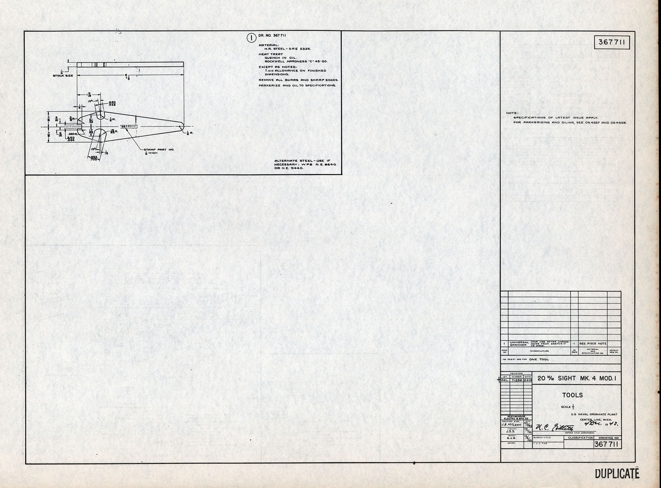