|
Search MARITIME.ORG
|
|
|
|
|
|
OP 805
(FIRST REVISION)
5-INCH TWIN GUN MOUNTS
MARK 28, 32, AND 38 ALL MODS
DESCRIPTION AND INSTRUCTIONS

19 MARCH 1957
|
ii
|

|
DEPARTMENT OF THE NAVY
BUREAU OF ORDNANCE
WASHINGTON 25, D. C.
|
19 March 1957
ORDNANCE PAMPHLET 805 (FIRST REVISION)
5-INCH TWIN GUN MOUNTS MARK 28, 32,
AND 38 ALL MODS - DESCRIPTION AND INSTRUCTIONS
1. Ordnance Pamphlet 805 (First Revision) provides descriptive information, as well as operating and maintenance instructions, for all service installations of 5-inch Mounts Mk 28, 32, and 38 all Mods.
2. Information and instructions in this publication are intended primarily for use by personnel engaged in the operation and maintenance of the equipment. All personnel so engaged should be familiar with the equipment's use, safe operation, casualty correction, disassembly, and maintenance. Thorough knowledge of the equipment is essential to its satisfactory operation.
3. This publication supersedes Ordnance Pamphlet 805, dated February 1942 and NAVORD OTI's G1-44 and G7-44, which should be destroyed.
|
iii
|
|
CONTENTS
| |
Page |
| CHAPTER 1 - GENERAL DESCRIPTION OF MOUNT |
| |
| Structural Assembly |
1 |
| Shield |
2 |
| Stand |
3 |
| Publication References |
5 |
| Ordnance Installations |
5 |
| Gun House Ordnance Arrangement |
9 |
| Gun and Slide Assembly |
9 |
| Gun Laying Equipment |
10 |
| Ammunition Hoist Equipment |
15 |
| Ammunition Handling Equipment and Stowage |
18 |
| Fire Control Equipment |
19 |
| Auxiliary Installations |
20 |
| Working Circle Data |
26 |
| Mount Design Data |
27 |
| |
| CHAPTER 2 - MOUNT OPERATION |
| |
| Introduction |
29 |
| Station Activities and Mount Control Methods |
29 |
| Mount Personnel Organization |
30 |
| Crew Stations |
30 |
| Gun Compartment Crew |
32 |
| Ammunition Handling Room Crew |
32 |
| Personnel Duties |
32 |
| Mount Captain |
32 |
| Pointer |
35 |
| Trainer |
37 |
| Sight Setter |
38 |
| Fuze Setter |
38 |
| Powder Men |
39 |
| Projectile and Rammer Men |
40 |
| Hot Case Man |
42 |
| Shell Guard Man |
42 |
| Sight Checker |
42 |
| Ammunition Handling Room Captain |
43 |
| Projectile Men |
43 |
| Powder Men |
45 |
| Personnel Duties with Rotating Ready Service Ammunition Rack |
45 |
| Preparing for Operation |
45 |
| Manning Stations |
46 |
| Starting Operations |
46 |
| Establishing Communications |
48 |
| Energizing Power Circuits |
48 |
| Ordnance Equipment Preparations |
48 |
| Ordnance Inspection and Testing |
48 |
| Ordnance Starting Operations |
48 |
| Control Systems: Setting Controls |
49 |
| Firing Operations |
49 |
| First Round |
49 |
|
|
| |
Page |
| Normal Semiautomatic Fire |
51 |
| Gun Laying and Firing |
51 |
| Gun Casualty Operation |
53 |
| Misfire Procedure |
53 |
| Breech Jam Clearance Procedure |
53 |
| Securing Operations |
55 |
| Stopping Equipment |
55 |
| Hoist Unloading Operations |
55 |
| Conditioning for Stowing |
55 |
| Securing |
55 |
| |
| CHAPTER 3 - GUN ASSEMBLIES |
| |
| General Description |
57 |
| Components |
57 |
| Design Differences |
57 |
| Gun Assembly Data |
58 |
| Detail Description |
59 |
| Gun |
59 |
| Gun Data |
59 |
| Housing Assembly |
61 |
| Housing Assembly Data |
61 |
| Housing Forging |
62 |
| Breech Mechanism |
63 |
| Safety Link Bracket |
69 |
| Recoil Mechanism |
69 |
| Counterrecoil Mechanism |
70 |
| Gas Ejector |
72 |
| Operation |
75 |
| Semiautomatic Fire |
75 |
| Single-Round Operations |
77 |
| Instructions |
79 |
| General Maintenance |
79 |
| Inspection |
79 |
| Monthly Test |
79 |
| Check for Bore Erosion |
81 |
| Lubrication, Preservation |
82 |
| Operating Instructions |
82 |
| Gun Maintenance Materials |
83 |
| Tools and Accessories |
84 |
| Gun Preservation Instructions |
84 |
| Breech Mechanism Preservation Instructions |
84 |
| Counterrecoil System Maintenance |
84 |
| Adjustments |
86 |
| Breechblock Adjustment |
86 |
| Recoil System Adjustments |
86 |
| Counterrecoil System Adjustment |
87 |
| Gas Ejector Adjustment |
87 |
| Trouble Analysis |
89 |
| Disassembly and Assembly |
89 |
| Regunning Instructions |
89 |
| Breech Mechanism Disassembly |
90 |
| Counterrecoil System Disassembly and Assembly |
92 |
| Gas Ejector Disassembly and Assembly.htm |
93 |
|
|
iv
|
| |
Page |
| |
|
| CHAPTER 4 - SLIDE ASSEMBLIES |
| |
| General Description |
95 |
| Components |
95 |
| Slide Data |
95 |
| Design Differences |
95 |
| Detail Description |
97 |
| Detail Description |
97 |
| Slide |
97 |
| Slide Weldment |
98 |
| Rear Plate |
98 |
| Case Tray and Guide Plate |
99 |
| Housing Guides |
99 |
| Circular Segment Bearing |
99 |
| Breech Mechanism Elements |
99 |
| Firing Mechanism Elements |
99 |
| Safety Link Device |
99 |
| Elevating Arc |
99 |
| Gun Port Shield |
99 |
| Balance Weights |
99 |
| Rammer Fixed Rack |
100 |
| Rammer |
100 |
| Rammer Data |
102 |
| Rammer Mechanism |
102 |
| Rammer Controls |
104 |
| Rammer Power Drive |
105 |
| Operation |
109 |
| Ram Mechanical Action |
109 |
| Ram Release Mechanical Action |
110 |
| Retract Action |
110 |
| Retract Release Mechanical Action |
112 |
| Ram Stroke Stalled Action |
113 |
| Rammer Stopping Action |
114 |
| Instructions |
114 |
| Stowing the Rammer |
116 |
| Adjustments |
116 |
| Circular Segment Gun-Bearing Adjustment |
116 |
| Rammer Speed Adjustment |
117 |
| Pilot Valve Adjustment |
117 |
| Relief Valve Adjustment |
117 |
| Buffer Valve Adjustment |
118 |
| Retract Limit Rod Adjustment |
118 |
| Trouble Analysis |
118 |
| Disassembly and Assembly |
119 |
| Rammer Removal |
119 |
| Rammer Cylinder Installation |
119 |
| Hydraulic Pump Motor Removal |
119 |
| Rammer Pump Removal |
119 |
| Pump and Valve Block Disassembly |
120 |
| Pump Installation |
120 |
| |
| CHAPTER 5 - CARRIAGE |
| |
| General Description |
121 |
| Components |
121 |
| Design Differences |
121 |
| Data |
123 |
| Detail Description |
124 |
| Base Ring |
124 |
| Gun Carriage Weldment |
125 |
| Operation |
127 |
|
|
| |
Page |
| Instructions |
129 |
| Operating Precautions |
129 |
| Servicing Instructions |
131 |
| Adjustments |
131 |
| Trouble Analysis |
132 |
| Assembly and Disassembly |
132 |
| |
| CHAPTER 6 - STAND |
| |
| General Description |
135 |
| Detail Description |
135 |
| Instructions |
137 |
| Disassembly and Assembly |
138 |
| |
| CHAPTER 7 - ELEVATING GEAR |
| |
| General Description |
141 |
| Components |
141 |
| Functional Arrangements |
141 |
| Design Differences |
142 |
| Detail Description |
143 |
| Mechanical System |
143 |
| Elevating Worm and Pinion Drive |
143 |
| Elevation Handwheel Drive Assembly |
146 |
| A-end Control Unit |
149 |
| Operation |
151 |
| Automatic Limit Stop Operation |
151 |
| Manual Drive Operation |
152 |
| Gunfire Reactions |
152 |
| Instructions |
| Manual Drive Procedure |
156 |
| Maintenance |
156 |
| Adjustments |
156 |
| Trouble Analysis |
159 |
| Disassembly and Assembly |
159 |
| |
| CHAPTER 8 - TRAINING GEAR |
| |
| General Description |
163 |
| Components |
164 |
| Functional Arrangement |
164 |
| Design Differences |
165 |
| Detail Description |
165 |
| Mechanical System |
165 |
| Training Worm and Pinion Drive |
165 |
| Train Handwheel Drive Assembly |
167 |
| Main Reduction Gear |
169 |
| A-end Control Unit |
171 |
| Manual Drive Operation |
174 |
| Instructions |
178 |
| Adjustments |
178 |
| Trouble Analysis |
181 |
| Disassembly and Assembly |
181 |
| |
| CHAPTER 9 - POWER DRIVES |
| |
| Power-Drive Systems |
183 |
| Electric Motor and Controller |
186 |
| Hydraulic Transmission System |
196 |
|
|
v
|
| |
Page |
| A-end |
198 |
| B-end |
202 |
| Auxiliary Pumps and Reduction Gear |
202 |
| Auxiliary Devices |
204 |
| Indicator-Regulators |
213 |
| Components |
213 |
| Functional Arrangement |
213 |
| Component Locations |
215 |
| Design Differences |
215 |
| Speed Data (Automatic and Local Control) |
215 |
| Indicating Equipment |
217 |
| Components |
217 |
| Parallax and Roller Path Wear Compensation |
225 |
| Control Equipment |
226 |
| Components |
229 |
| Local Control Friction Drive |
229 |
| Synchro Power-Failure Device |
229 |
| Fine and Coarse Control Synchro Motors |
230 |
| Relief Cam Assemblies |
230 |
| Differential Cam Assembly |
230 |
| Regulator Valve Block |
233 |
| Coarse Pilot Valve Block |
234 |
| Reaction to Change in Signal |
235 |
| Synchronizing Control Device |
240 |
| Synchronizing Control Device Action |
242 |
| Auxiliary Devices |
251 |
| Regulating and Relief Valve Actions |
254 |
| Auxiliary Devices Operation |
254 |
| Indicator-Regulator Drain Arrangement |
256 |
| Operation |
261 |
| Hand Control Operation |
261 |
| Protective Device Operation |
265 |
| Local Control Operation |
265 |
| Automatic Control Operation |
265 |
| Control Pressure System |
266 |
| General Operating Precautions |
267 |
| Parallax Correction Instructions |
287 |
| Control Selection |
267 |
| Securing the Power Drives |
268 |
| Instructions for Casualty Operation |
268 |
| Operating Precautions |
268 |
| Service Instructions |
269 |
| Maintenance |
270 |
| Exercise Operation |
271 |
| General Adjustments |
271 |
| Indicator-Regulator Adjustments |
273 |
| Elevation Indicator-Regulator Mk 42 Adjustments |
273 |
| Train Indicator-Regulator Mk 46 Adjustments |
278 |
| Elevation Indicator-Regulator Mk 34 Adjustments |
285 |
| Train Indicator-Regulator Mk 38 Adjustments |
292 |
| Dynamic Control Test |
297 |
| Trouble Analysis |
298 |
| Installation of Indicator-Regulators |
301 |
| Disassembly |
302 |
| Piping Removal and Replacement |
302 |
|
|
| |
Page |
| Power Drive Equipment Removal |
302 |
| Indicator-Regulator Disassembly |
307 |
| Disassembly of Fine Pilot and Amplifier Valves |
311 |
| Disassembly of Coarse Pilot Valve |
311 |
| Disassembly of Acceleration Valve and Valve Tube |
311 |
| Disassembly of Remaining Valves in the Regulator Valve Block |
312 |
| Assembly |
313 |
| Installing the Fine Control Synchro |
313 |
| Installing the Differential Cam Assembly |
313 |
| |
| CHAPTER 10 - PROJECTILE HOISTS |
| |
| General Description |
315 |
| Detail Description |
316 |
| Power Drive |
316 |
| Conveyor |
319 |
| Central Column |
320 |
| Fuze Setter Mechanism |
320 |
| Hoist Controls |
323 |
| Operation |
326 |
| Instructions |
328 |
| Maintenance |
328 |
| Operating Precautions |
329 |
| Trouble Analysis |
329 |
| Adjustments |
330 |
| Conveyor Chain Tension Adjustment |
331 |
| Lower-End Control Gear Adjustments |
331 |
| Upper-End Control Gear Adjustments |
335 |
| Starting Valve Linkage Adjustment |
339 |
| Disassembly and Assembly |
340 |
| |
| CHAPTER 11 - PROJECTILE HOIST POWER DRIVE (VICKERS) |
| |
| General Description |
343 |
| Components |
343 |
| Design Differences |
343 |
| Detail Description |
343 |
| Power Unit |
343 |
| Hoist Drive Unit |
346 |
| Operation |
350 |
| Power Drive Operation Cycle |
352 |
| Manual Drive |
358 |
| Instructions |
359 |
| General Maintenance |
359 |
| Installation Instructions |
359 |
| Operating Precautions |
359 |
| Hydraulic Equipment Servicing |
360 |
| Trouble Analysis |
360 |
| Adjustments |
364 |
| Disassembly and Assembly |
367 |
| Power Unit Disassembly and Assembly |
367 |
| Hydraulic Motor Removal |
367 |
| Hoist Drive Unit Removal |
368 |
| Valve Block Removal |
369 |
| Hydraulic Brake and Hand Drive Unit Removal |
370 |
|
|
vi
|
| |
Page |
| |
| CHAPTER 12 - PROJECTILE HOIST POWER DRIVE (NORTHERN ORDNANCE) |
| |
| General Description |
371 |
| Detail Description |
371 |
| Power Unit |
371 |
| Hoist Drive Unit |
374 |
| Operation |
381 |
| Power Drive Operating Cycle |
381 |
| Manual Drive |
385 |
| Instructions |
386 |
| Maintenance |
386 |
| Installation Instructions |
386 |
| Operating Precautions |
386 |
| Hydraulic Equipment Servicing |
387 |
| Trouble Analysis |
387 |
| Adjustments |
389 |
| Disassembly and Assembly |
391 |
| |
| CHAPTER 13 - POWDER HOISTS |
| |
| General Description |
393 |
| Components |
393 |
| Functional Arrangement |
393 |
| Design Differences |
393 |
| Detail Description |
394 |
| Hoist Tube |
394 |
| Power Drive |
397 |
| Hoist Manual Drive (Vickers) |
397 |
| Hoist Manual Drive (Northern Ordnance) |
397 |
| Hoist Controls |
398 |
| Operation |
401 |
| Instructions |
401 |
| General Maintenance |
401 |
| Operating Precautions |
402 |
| Trouble Analysis |
402 |
| Adjustments |
402 |
| Disassembly and Assembly |
405 |
| General Instructions |
405 |
| |
| CHAPTER 14 - POWDER HOIST POWER DRIVE (VICKERS) |
| |
| General Description |
407 |
| Detail Description |
407 |
| Power Unit |
407 |
| Hoist Drive Unit |
408 |
| Operation |
412 |
| Power Drive Operating Cycle |
412 |
| Manual Drive |
419 |
| Instructions |
419 |
| General Maintenance |
419 |
| Installation Instructions |
419 |
| Operating Precautions |
419 |
| Hydraulic Equipment Servicing |
420 |
| Trouble Analysis |
420 |
| Adjustments |
423 |
| Disassembly and Assembly |
424 |
| Power Unit Disassembly and Assembly |
425 |
| Hoist Drive Unit Disassembly and Assembly |
425 |
| General Assembly Instructions |
426 |
|
|
| |
Page |
| |
| CHAPTER 15 - POWDER HOIST POWER DRIVE (NORTHERN ORDNANCE) |
| |
| General Description |
427 |
| Detail Description |
429 |
| Power Unit |
429 |
| Hoist Drive Unit |
429 |
| Operation |
433 |
| Power Drive Operating Cycle |
433 |
| Manual Operation |
435 |
| Instructions |
440 |
| General Maintenance |
440 |
| Installation Instructions |
440 |
| Operating Precautions |
440 |
| Hydraulic Equipment Servicing |
440 |
| Trouble Analysis |
441 |
| Adjustments |
443 |
| Disassembly and Assembly |
444 |
| |
| CHAPTER 16 - FUZE SETTING INDICATOR-REGULATOR, EARLY TYPE, FUZE SETTING INDICATOR-REGULATOR MK 8 MODS 4, 7 |
| |
| General Description |
447 |
| Components |
447 |
| Arrangement |
447 |
| Design Differences |
448 |
| Data |
448 |
| Detail Description |
448 |
| Dials and Indicators |
448 |
| Indicating Synchro Motors |
449 |
| Follow-up Heads |
450 |
| Pilot Motor |
453 |
| Power Motor |
453 |
| Power Control Head |
454 |
| Overload Device |
456 |
| Limit Stop Mechanism |
456 |
| Selector Mechanism |
459 |
| Electrical System |
459 |
| Operation |
459 |
| Automatic Control Operation |
459 |
| Manual Drive Operation |
462 |
| Instructions |
463 |
| Operating Instructions |
463 |
| Operating Precautions |
463 |
| Maintenance Instructions |
464 |
| Trouble Analysis |
464 |
| Adjustment |
465 |
| Disassembly and Assembly |
467 |
| |
| CHAPTER 17 - FUZE SETTING INDICATOR-REGULATOR MK 9 MODS 0, 1 |
| |
| General Description |
473 |
| Components |
473 |
| Detail Description |
475 |
| Indicating Dials |
475 |
| Indicating Synchro Motors |
475 |
| Low Speed Follow-up Head |
477 |
|
|
vii
|
| |
Page |
| Power Control Synchro and Power Control Head |
477 |
| Power Motor |
480 |
| Overload Device |
481 |
| Limit Stop Mechanism |
481 |
| Friction Clutch |
485 |
| Selector Mechanism |
486 |
| Electrical System |
486 |
| Operation |
487 |
| Principle of Operation of Power Control Head |
487 |
| Automatic Control |
488 |
| Manual Drive |
490 |
| Instructions |
490 |
| Operating Instructions |
490 |
| Operating Precautions |
490 |
| Maintenance |
490 |
| Trouble Analysis |
499 |
| Adjustments |
500 |
| Disassembly and Assembly |
503 |
| |
| CHAPTER 18 - SIGHTS |
| |
| General Description |
505 |
| Detail Description |
510 |
| Sight Mk 36 Mod 0 |
510 |
| Telescopes Mk 67 Mod 0 and Mk 68 Mod 0 |
510 |
| Sight Setter's Indicator Mk 4 Mod 0 |
513 |
| External Shafting and Gearing System |
519 |
| Mount Captain's Open Sight Mk 39 Mods 0, 2, and 6 |
521 |
| Operation |
523 |
| 5-Inch Sight Mk 36 Mod 0 Operation |
523 |
| Instructions |
524 |
| Maintenance |
524 |
| Adjustments |
525 |
| Disassembly and Assembly |
529 |
| |
| CHAPTER 19 - SHIELDS |
| |
| General Description |
533 |
| Components |
533 |
| Design Differences |
533 |
| Detail Description |
536 |
| Instructions |
545 |
| Maintenance |
545 |
| Trouble Analysis |
545 |
| Adjustments |
546 |
| Disassembly and Assembly |
547 |
| |
| CHAPTER 20 - ELECTRICAL INSTALLATION |
| |
| General Description |
551 |
| Cognizance |
551 |
| Major Components and Circuits |
551 |
|
|
| |
Page |
| Detail Description |
553 |
| Power System |
553 |
| Main Power Supply |
553 |
| Power Motors |
554 |
| Controllers and Associated Equipment |
556 |
| Electric Power Motor Data |
557 |
| Space Heaters |
565 |
| Controller Data (Ordnance) |
566 |
| Design Differences |
568 |
| Components |
568 |
| Emergency Power Supply Storage Battery |
568 |
| Firing Circuit |
568 |
| Instrument and Battle-Station Lighting Circuit |
572 |
| General Lighting Circuit |
574 |
| Components |
575 |
| Fire Control Circuits |
580 |
| Components |
580 |
| Communication Circuits |
581 |
| Components |
581 |
| Gun Collision Prevention Circuit |
583 |
| Instructions |
584 |
| General Care |
584 |
| Power System Maintenance |
584 |
| Firing and Lighting Circuit Maintenance |
585 |
| General Lighting Circuit Maintenance |
585 |
| Fire-Control Circuits Maintenance |
586 |
| Communication Circuits Maintenance |
|
| |
| CHAPTER 21 - TOOLS AND ACCESSORIES |
| |
| Special Equipment |
587 |
| Standard Equipment |
587 |
| |
| CHAPTER 22 - HYDRAULIC EQUIPMENT INSTRUCTIONS |
| Installation Instructions |
611 |
| Maintenance Instructions |
613 |
| |
| CHAPTER 23 - LUBRICATING INSTRUCTIONS |
| |
| Charts |
617 |
| Lubrication Chart Check-off Lists |
618 |
| |
| APPENDIX |
| |
| Mount Ordnance Data |
619 |
| |
| SAFETY PRECAUTIONS |
621 |
| |
| INDEX |
623 |
|
|
viii
|
|
ILLUSTRATIONS
| Figure |
Title |
Page |
| |
| CHAPTER 1 |
| |
| Front |
5-inch 38-cal. Twin Mount. Installed Arrangement. |
xxii |
| 1 |
5-inch Mount Mk 32 Mod 4. Left Front View. |
2 |
| 2 |
5-inch Mount Mk 32 Mod 4. Rear View. |
3 |
| 3 |
5-inch Mount Mk 32 Mod 2. Shield Removed - Front View. |
4 |
| 4 |
5-inch Mount Mk 32 Mod 2. Shield Removed - Right Side. |
5 |
| 5 |
5-inch Mount Mk 32 Mod 2. Shield Removed - Left Side. |
6 |
| 6 |
5-inch Mount Mk 38 Mods. Ordnance Equipment Arrangement. Plan View. |
7 |
| 7 |
5-inch Mount Mk 32 Mods. Ordnance Equipment Arrangement. Plan View. |
8 |
| 8 |
5-inch Mount Mk 28 Mods. General Arrangement. Longitudinal Section. |
12 |
| 9 |
5-inch Mount Mk 32 Mods. General Arrangement. Longitudinal Section. |
13 |
| 10 |
5-inch Mount Mk 38 Mods. General Arrangement. Longitudinal Section. |
14 |
| 11 |
Projectile Hoist - General Arrangement. Lower End. |
16 |
| 12 |
Powder Hoist - General Arrangement. Lower End. |
17 |
| 13 |
Mount Captain's Station. General Arrangement. |
21 |
| 14 |
5-inch Mount Mk 28 Mods. Working Circle. |
23 |
| 15 |
5-inch Mount Mk 32 Mods. Working Circle. |
24 |
| 16 |
5-inch Mount Mk 38 Mods. Working Circle. |
25 |
|
|
| Figure |
Title |
Page |
| |
| CHAPTER 2 |
| |
| 17 |
5-inch Mounts Mk 28, 32, and 38. Gun House. Personnel Arrangement. |
30 |
| 18 |
5-inch Mounts Mk 28 and 32. Ammunition Handling Room. Personnel Arrangement. |
31 |
| 19 |
5-inch Mount Mk 38. Ammunition Handling Room. Personnel Arrangement. |
33 |
| 20 |
Mount Captain's Station, General Arrangement. |
34 |
| 21 |
Pointer's and Checker's Stations. General Arrangement. |
35 |
| 22 |
Trainer's Station. General Arrangement. |
37 |
| 23 |
Sight Setter's Station, General Arrangement. |
39 |
| 24 |
5-inch Mount Mk 38. Inner Ammunition Handling Room. Projectilemen's Stations. |
41 |
| 25 |
Extraction of Cartridge Case. |
42 |
| 26 |
5-inch Mount Mk 38. Inner Ammunition Handling Room. Powdermen's Stations. |
44 |
| 27 |
5-inch Mount Mk 38. Outer Ammunition Handling Room. |
46 |
| 28 |
Training Gear and Controls. Functional Diagram. |
50 |
| 29 |
Elevating Gear and Controls. Functional Diagram. |
52 |
| 30 |
Sight. Schematic Diagram. |
54 |
| |
| CHAPTER 3 |
| |
| 31 |
Gun Assembly. Installed Arrangement. |
56 |
|
|
ix
|
| Figure |
Title |
Page |
| |
|
| 32 |
Structural Support of Gun and Housing in Slide. |
58 |
| 33 |
Gun and Housing. Section. |
59 |
| 34 |
Gun Securing Key Assembly. Old Design. |
60 |
| 35 |
Gun Securing Key Assembly. New Design. |
60 |
| 36 |
Gun Assembly. Plan View. |
60 |
| 37 |
Gun Assembly. Right Side. |
60 |
| 38 |
Breech Mechanism. Installed Arrangement. Section. |
61 |
| 39 |
Breech and Extractor Mechanisms. Installed Arrangement. |
62 |
| 40 |
Breech Operating Mechanism. Section. |
63 |
| 41 |
Breechblock and Operating Shaft Mechanisms. Section. |
64 |
| 42 |
Breechblock and Extractors Assembly. |
65 |
| 43 |
Breechblock and Operating Shaft Assembly. Bottom View. |
65 |
| 44 |
Hand Closing Latch Assembly. Section. |
66 |
| 45 |
Salvo Latch and Cam Plate Retractor Mechanism. |
66 |
| 46 |
Adapter Bolt for Cam Plate Retraction. |
67 |
| 47 |
Firing Pin Mechanism. Section. |
68 |
| 48 |
Safety Link Bracket. Assembled Arrangement. |
69 |
| 49 |
Recoil Mechanism. Section. |
70 |
| 50 |
Recoil Mechanism Cylinder Head. Section. |
70 |
| 51 |
Counterrecoil Mechanism. Section. |
71 |
| 52 |
Gas Ejector Piping System. General Arrangement. |
72 |
| 53 |
Gas Ejector Air Valve Mechanism. Assembled Arrangement. |
73 |
|
|
| Figure |
Title |
Page |
| |
| 54 |
Breech Mechanism Operation. Breech Closed. |
74 |
| 55 |
Gun Firing Operation. Breech Closed. |
75 |
| 56 |
Gun Firing Operation. Cam Plate Action. Counterrecoil Movement. Breech Closed. |
75 |
| 57 |
Gun Firing Operation. Cam Plate Action. Counterrecoil Movement. Breech Open. |
75 |
| 58 |
Gun Firing Operation. Cam Plate Action. Gun in Battery. Breech Open. |
76 |
| 59 |
Gun Firing Operation. Breech Closed. Extractors Engaged. |
76 |
| 60 |
Gun Firing Operation. Breech Open. Extractor Action. |
77 |
| 61 |
Breech Mechanism Operation. Breech Open. |
78 |
| 62 |
Firing Mechanism Operation. Breech Opening. Mid Position. |
78 |
| 63 |
Gun Firing Operation. Cam Plate Action. Ammunition Rammed. Breech Closed. |
78 |
| 64 |
Firing Mechanism Operation. Breech Closing. Near Closed Position. |
79 |
| 65 |
Firing Mechanism Operation. Breech Closed. |
79 |
| 66 |
Counterrecoil System Servicing Connections and Accessories. |
80 |
| 67 |
Breechblock Releasing Tool. |
82 |
| 68 |
Breech Operating Spring. Adjustment. |
86 |
| 69 |
Recoil System Buffer Choke. Adjustment. |
87 |
| 70 |
Recoil Piston Rod Packing. Adjustment. |
87 |
| 71 |
Differential Piston Rod. Adjustment. |
88 |
| 72 |
Gas Ejector Cut-off Valve. Adjustment. |
88 |
|
|
x
|
| Figure |
Title |
Page |
| |
| 73 |
Breech Mechanism Disassembly. Cam Tool Assembly. |
90 |
| 74 |
Special Tool for Removal of Breech Operating Spring. |
90 |
| 75 |
Breech Mechanism Reassembly. Extractor Spring Plunger. Compressor Installed. |
91 |
| 76 |
Breech Mechanism Reassembly. Extractors Inserted. |
91 |
| 77 |
Breech Mechanism Reassembly. Bearing Block Installation. |
92 |
| 78 |
Counterrecoil Mechanism. Disassembly. |
93 |
| |
| CHAPTER 4 |
| |
| 79 |
5-inch Slide Mk 27. Installed Arrangement of Right Slide. |
96 |
| 80 |
5-inch Slide Mk 27. Installed Arrangement of Left Slide. |
97 |
| 81 |
Right Slide. Gun Port Shield and Rammer Removed. Right Front View. |
98 |
| 82 |
Gun Port Shield. Left Gun. Assembled Arrangement. |
103 |
| 83 |
Right Slide Rammer. Assembled Arrangement. Left Side. |
101 |
| 84 |
Right Slide Rammer. Assembled Arrangement. Right Side. |
101 |
| 85 |
Right Slide Rammer. Crosshead Assembly. |
102 |
| 86 |
Right Slide Rammer Controls. |
103 |
| 87 |
Rammer Retract Limit Link Assembly. |
104 |
| 88 |
Rammer Cylinder and Piston. Section. |
105 |
| 89 |
Rammer Power Plant. |
107 |
| 90 |
Rammer Pump and Main Valve Block. Section. |
107 |
| 91 |
Rammer Pilot Valve Block Assembly. Exploded. |
108 |
| 92 |
Rammer Operation. Ramming. Initial Position. |
109 |
| 93 |
Rammer Operation. Ramming. Rammed Position. |
110 |
|
|
| Figure |
Title |
Page |
| |
| 94 |
Rammer Operation. Retraction. Initial Position after Recoil. |
111 |
| 95 |
Rammer Operation. Retraction. Final Position. |
111 |
| 96 |
Rammer Circuit Diagram. Start of Ram Stroke. |
112 |
| 97 |
Rammer Circuit Diagram. Mid-Position of Ram Stroke. |
112 |
| 98 |
Rammer Circuit Diagram. End of Ram Stroke. |
113 |
| 99 |
Rammer Circuit Diagram. Start of Retraction. |
113 |
| 100 |
Rammer Circuit Diagram. End of Retraction. |
113 |
| 101 |
Rammer Circuit Diagram. Ram Stroke Stalled. |
113 |
| 102 |
Circular Segment Gun Bearing. Adjustment. |
116 |
| 103 |
Pilot Valve. Adjustment. |
117 |
| 104 |
Relief Valve. Adjustment. |
118 |
| 105 |
Buffer Valve. Adjustment. |
118 |
| |
| CHAPTER 5 |
| |
| 106 |
5-inch Carriage Mk 31. General Arrangement. |
122 |
| 107 |
5-inch Carriage Mk 31. Water Seal and Roller Bearings. Installed Arrangement. |
123 |
| 108 |
5-inch Carriage Mk 27. Water Seal and Roller Bearings. Installed Arrangement. |
123 |
| 109 |
Training Stop Buffer. |
125 |
| 110 |
Train Centering Pin, Section. |
125 |
| 111 |
5-inch Carriage Mk 31 Mod 1. Water Seal and Roller Bearings. Section. |
126 |
| 112 |
5-inch Carriage Mk 27 Mods 0, 2, 6, 7, 9, 12, 13, 14. Water Seal. Section. |
126 |
| 113 |
Slide Trunnion Bearing. Left Trunnion Bearing Assembly. Right Gun. |
127 |
|
|
xi
|
| Figure |
Title |
Page |
| |
| 114 |
Foot Firing Mechanism and Firing Stop Mechanism, Schematic. |
128 |
| 115 |
5-inch Mount Mk 38. Tram Arrangement. |
129 |
| 116 |
Firing Stop Mechanism. Adjustment. |
130 |
| 117 |
Holding-Down Clip. Adjustment. |
131 |
| 118 |
5-inch Stand Mk 17 Mod 1. General Arrangement. |
136 |
| |
| CHAPTER 6 |
| |
| 119 |
5-inch Stand Mk 16 Mod 3. General Arrangement. |
137 |
| 120 |
5-inch Stand Mk 16 Mod 3. Section. |
138 |
| 121 |
5-inch Stand Mk 17 Mod 1. Section. |
138 |
| 122 |
Horizontal Bearing Separators Clamp. Disassembled. |
139 |
| |
| CHAPTER 7 |
| |
| 123 |
5-inch Elevating Gear Mk 10 Installed Arrangement. Front View. |
142 |
| 124 |
5-inch Elevating Gear Mk 10. Installed Arrangement. Left Side View. |
143 |
| 125 |
5-inch Elevating Gear Mks 9 and 10. Mechanical Schematic. |
144 |
| 126 |
5-inch Mount Mk 32. Pointer's and Checker's Station. |
145 |
| 127 |
5-inch Elevating Gear Mks 9 and 10. Handwheel Drive Assembly and B-End. Left Rear View. |
146 |
| 128 |
5-inch Elevating Gear Mks 9 and 10. Handwheel Drive Assembly and B-End. Front View. |
146 |
| 129 |
5-inch Elevating Gear Mks 9 and 10. Manual Drive Gearing Schematic. |
147 |
|
|
| Figure |
Title |
Page |
| |
| 130 |
Planetary Reduction Gear. |
148 |
| 131 |
Elevating Gear Auxiliary Pumps Reduction Gear. |
149 |
| 132 |
Elevating Gear Mks 9 and 10. A-End Control Unit. |
149 |
| 133 |
Elevating Gear A-End Control Unit. Section. |
150 |
| 134 |
5-inch Elevating Gear Mks 9 and 10. Hand Control and 153, Manual Drive Gearing Systems. |
154 |
| 135 |
Elevating Gear Anti-Overhaul Mechanism. Normal Operation. Increasing Elevation. Schematic. |
155 |
| 136 |
Elevating Gear Anti-Overhaul Mechanism. Anti-Kick Control. Increasing Elevation. Schematic. |
155 |
| 137 |
Elevating Gear Anti-Overhaul Mechanism. Anti-Overhaul Control. Schematic. |
155 |
| 138 |
Elevating Worm. Adjustment. |
157 |
| 139 |
Elevating Gear Anti-Overhaul Mechanism. Adjustment. |
158 |
| 140 |
Elevating Gear Limit Stop Key and Clamp. Adjustment. |
159 |
| |
| CHAPTER 8 |
| |
| 141 |
5-inch Training Gear Mk 10. Installed Arrangement. Front View. |
163 |
| 142 |
5-inch Training Gear. Installed Arrangement. Right Side. |
164 |
| 143 |
5-inch Training Gear Mks 9 and 10. Mechanical Schematic. |
166 |
| 144 |
5-inch Mount Mk 32. Trainer's Station. |
167 |
| 145 |
5-inch Training Gear Mks 9 and 10. Hydraulic Transmission, Indicator-Regulator, and Hand-wheel Drive Assembly. |
168 |
| 146 |
5-inch Training Gear Mks 9 and 10. Handwheel Drive Assembly. Rear View. |
169 |
|
|
xii
|
| Figure |
Title |
Page |
| |
| 147 |
5-inch Training Gear Mks 9 and 10. Manual Drive. Schematic. |
170 |
| 148 |
Train Reduction Gear. Section Through Input Shaft. |
171 |
| 149 |
Training Gear. A-End Control Unit. Top View. |
172 |
| 150 |
Train A-End Control Unit. Section. |
173 |
| 151 |
5-inch Training Gear Mks 9 and 10. Hand Control and Manual Drive Gearing Systems. |
175, 176 |
| 152 |
Elevating Gear Anti-Overhaul Mechanism. Normal Operation. Increasing Elevation. Schematic. |
177 |
| 153 |
Elevating Gear Anti-Overhaul Mechanism. Anti-Kick Control. Increasing Elevation. Schematic. |
177 |
| 154 |
Elevating Gear Anti-Overhaul Mechanism. Anti-Overhaul Control. Schematic. |
178 |
| 155 |
Training Worm. Adjustment. |
179 |
| 156 |
Train Limit Stop Key and Clamp. Adjustment. |
180 |
| |
| CHAPTER 9 |
| |
| 157 |
5-inch Elevating Gear Mks 9 and 10. Power Drive Unit. Right Front View. |
183 |
| 158 |
5-inch Elevating Gear Mks 9 and 10. Power Drive Unit. Left Rear View. |
184 |
| 159 |
5-inch Training Gear Mks 9 and 10. Electric Hydraulic Power Drive. Right Front View. |
185 |
| 160 |
5-inch Training Gear Mks 9 and 10. Electric Hydraulic Power Drive. Left Rear View. |
185 |
| 161 |
Shield Access Port. Elevating Side. |
186 |
| 162 |
5-inch Elevating Gear Mks 9 and 10. Automatic and Local Control Gearing Systems. |
187, 188 |
|
|
| Figure |
Title |
Page |
| |
| 163 |
5-inch Training Gear Mks 9 and 10. Automatic and Local Control Gearing Systems. |
189, 190 |
| 164 |
5-inch Elevating Gear Mk 10. Piping Diagram. New Arrangement. |
191 |
| 165 |
5-inch Elevating Gear Mk 10. Piping Diagram. Old Arrangement. |
192 |
| 166 |
5-inch Elevating Gear Mk 5. Piping Diagram. New Arrangement. |
193 |
| 167 |
5-inch Elevating Gear Mk 5. Piping Diagram. Old Arrangement. |
194 |
| 168 |
Training Gear Piping Schematic. New Arrangement. |
195 |
| 169 |
Training Gear Piping Schematic. Old Arrangement. |
196 |
| 170 |
Train A-End. Front View. |
197 |
| 171 |
Train A-End. Section. |
198 |
| 172 |
Elevating Gear A-End Tilting Box. Section. |
199 |
| 173 |
Train Hydraulic Power System. A-End Valve Plate. |
200 |
| 174 |
Elevating Gear Stroke Control and Main Cylinder. Section. |
201 |
| 175 |
Elevating Gear A-End Stroking Arm. Vertical Section. |
202 |
| 176 |
Elevating Gear B-End. |
203 |
| 177 |
Elevating Gear Sump Pump. |
204 |
| 178 |
Train Gear Replenishing Pump. Section. |
205 |
| 179 |
Elevating Gear Control Pressure Pump. Section. |
205 |
| 180 |
Replenishing Oil Filters. Section. |
206 |
| 181 |
Train Anti-Overhaul Valve Block. Section. |
206 |
| 182 |
Elevating Gear Anti-Overhaul Mechanism. Schematic. Guns Stationary. V-AO at Neutral. |
207 |
|
|
xiii
|
| Figure |
Title |
Page |
| |
| 183 |
Power Failure Solenoid and Valve. Normal Position. Section. |
208 |
| 184 |
Control Pressure Filters. Section. |
209 |
| 185 |
Auxiliary Exhaust Filter. Section. |
209 |
| 186 |
Selector Valve. Automatic Control Position. |
211 |
| 187 |
Selector Valve. Local Control Position. |
211 |
| 188 |
Selector Valve. Hand Control Position. |
212 |
| 189 |
Selector Valve. Manual Drive Position. |
212 |
| 190 |
Elevation Indicator-Regulator Mk 42. Plan View. |
214 |
| 191 |
Elevation Indicator-Regulator Mk 42. Right Rear View. |
215 |
| 192 |
Train Indicator-Regulator Mk 46. Plan View. |
216 |
| 193 |
Train Indicator-Regulator Mk 46. Right Rear View. |
217 |
| 194 |
Elevation Indicator-Regulator Gearing Schematic. |
218 |
| 195 |
Train Indicator-Regulator Gearing. Schematic. |
219 |
| 196 |
Elevation Indicator-Regulator Mk 42. Wiring Diagram. |
220 |
| 197 |
Train Indicator-Regulator Mk 46. Wiring Diagram. |
221 |
| 198 |
Elevation Indicator-Regulator Mk 34. Wiring Diagram. |
222 |
| 199 |
Train Indicator-Regulator Mk 38. Wiring Diagram. |
223 |
| 200 |
Elevation Indicator-Regulator Mk 42. Roller Path Inclination Dial. |
225 |
| 201 |
Train Indicator-Regulator Mk 46. Parallax Cam and Contact Assemblies. |
226 |
| 202 |
Elevator and Train Indicator-Regulators Mks 42 and 46. Receiver Assembly. Schematic. |
227 |
|
|
| Figure |
Title |
Page |
| |
| 203 |
Local Control Mechanism. |
228 |
| 204 |
Synchro Power-Failure Device |
229 |
| 205 |
Elevation Indicator-Regulator Mk 42 and Train Indicator-Regulator Mk 46. Automatic Control Circuit. Hydraulic Schematic. |
231, 232 |
| 206 |
Fine Pilot and Amplifier Valves. |
233 |
| 207 |
Regulator Control Circuit Following Signal of Uniform Velocity. |
237 |
| 208 |
Regulator Control Circuit Following Signal of Uniform Acceleration. |
238 |
| 209 |
Regulator Control Circuit Following Signal of Increasing Acceleration. |
239 |
| 210 |
Synchronizing Control Device. Intermittent Drive. Drive Meshed at Point of Transfer. |
240 |
| 211 |
Offset Control Valve. Position for Error Greater Than 1.5 Degrees. Right Train or Elevation. |
241 |
| 212 |
Offset Control Valve. Position for Error Greater Than 1.5 Degrees. Left Train or Depression. |
241 |
| 213 |
Synchronizing Supply Pressure Reducing Valve and Offset Pressure Reducing Valve. |
242 |
| 214 |
Elevation and Train Indicator-Regulators Mks 42 and 46. Synchronizing Control Device. Hydraulic Schematic. |
244 |
| 215 |
Elevation and Train Indicator-Regulators Mks 42 and 46. Automatic Control Circuit. Error Greater Than 3.8 Degrees. |
245 |
| 216 |
5-inch Elevating Gear Mks 9 and 10. Hydraulic Schematic. Automatic Control. |
247, 248 |
| 217 |
5-inch Training Gear Mks 9 and 10. Hydraulic Schematic. Automatic Control. |
249, 250 |
|
|
xiv
|
| Figure |
Title |
Page |
| |
| 218 |
Elevation and Train Indicator-Regulators Mks 42 and 46. Automatic Control Circuit. Error Reduced One-Half by Apparent Response. |
252 |
| 219 |
Elevation Indicator-Regulator Mk 42. Right Rear View. Covers Removed. |
253 |
| 220 |
High Pressure Regulating Valve. |
254 |
| 221 |
Low Pressure Reducing Valve. |
255 |
| 222 |
Intermediate High Pressure Relief Valve. |
255 |
| 223 |
Sump Pump and Oscillator. |
256 |
| 224 |
5-inch Elevating Gear Mk 5. Hydraulic Schematic. Automatic Control |
257, 258 |
| 225 |
5-inch Training Gear Mk 5. Hydraulic Schematic. Automatic Control |
259, 260 |
| 226 |
Elevation and Train Indicator-Regulators Mks 34 and 38. Oscillator Valve Positions. |
261 |
| 227 |
5-inch Elevating Gear Mks 9 and 10. Hydraulic Schematic. Hand Control. |
263, 264 |
| 228 |
Train Indicator-Regulator Parallax Friction Drive. Adjustment. |
267 |
| 229 |
Acceleration Valve. Two Slot Tube. Legend Plate. |
269 |
| 230 |
Control Pressure Pump Relief Valve. Adjustment. |
272 |
| 231 |
Train B-End Relief Valve. Adjustment. |
272 |
| 232 |
Indicator-Regulator Electrical Zero Circuit. |
273 |
| 233 |
Elevation and Train Indicator-Regulators Mks 42 and 46. Valve Blocks and Synchro Power-Failure Device. |
274 |
| 234 |
Elevation Indicator-Regulator Mk 42. Left Rear View. |
275 |
| 235 |
Elevation Handwheel Drive Assembly. Adjustments A-14 and A-13. |
276 |
|
|
| Figure |
Title |
Page |
| |
| 236 |
Special Tools for Disassembly and Assembly of Elevation and Train Indicator-Regulators. |
276 |
| 237 |
Adjustments A-2 and A-3. |
276 |
| 238 |
Elevation and Train Indicator-Regulators Mks 42 and 46. Regulating Equipment. |
277 |
| 239 |
Train Indicator-Regulator Mk 46. Right Rear View. Covers Removed. |
279 |
| 240 |
Train Indicator-Regulator Mk 46. Case Interior. |
280 |
| 241 |
Train Indicator-Regulator Mk 46. Left Rear View. Covers Removed. |
281 |
| 242 |
Train Handwheel Drive Assembly. Adjustment A-17. |
282 |
| 243 |
Train Indicator-Regulator Mk 46. Cover No. 5 Removed. |
283 |
| 244 |
Train Indicator-Regulator Mk 46. Adjustment A-3. |
283 |
| 245 |
Train Indicator-Regulator Mk 46. Adjustment A-20. |
285 |
| 246 |
5-inch Training Gear Mks 9 and 10. Adjustment A-18 in Handwheel Drive Assembly. |
285 |
| 247 |
Elevation and Train Indicator-Regulators Mks 34 and 38. Synchro Power-Failure Device and Valve Blocks. |
286 |
| 248 |
Elevation Indicator-Regulator Mk 34. Left Rear View. Covers Removed. |
287 |
| 249 |
Elevation Indicator -Regulator Mk 34. Right Rear View. Covers Removed. |
288 |
| 250 |
Elevation Indicator-Regulator Mk 34. Case Interior. Adjustment A-10 and A-9. |
289 |
| 251 |
Adjustment of Synchro Power Failure Device. (Auto Control.) |
290 |
| 252 |
Elevation and Train Indicator-Regulators Mks 34 and 38. Regulating Equipment. |
291 |
|
|
xv
|
| Figure |
Title |
Page |
| |
| 253 |
Train Indicator-Regulator Mk 38. Case Interior. |
293 |
| 254 |
Train Indicator-Regulator Mk 38. Left Rear View. Covers Removed. |
294 |
| 255 |
Train Indicator-Regulator Mk 38. Right Rear View. Covers Removed. |
295 |
| 256 |
5-inch Mount Mk 32. Shield Access Port to Elevation Indicator-Regulator. |
302 |
| 257 |
5-inch Mount Mk 32. Shield Access Port to Train Indicator-Regulator. |
303 |
| 258 |
Indicator Assembly. Removal. |
307 |
| 259 |
Fine Control Synchro Unit. Removal. |
308 |
| 260 |
Automatic Receiver Assembly. Removal. |
308 |
| 261 |
Regulating Valve Blocks and Synchronizing Control Device. Disassembled. |
309 |
| 262 |
Indicator-Regulator Case. Automatic Receiver Assembly Removed. |
310 |
| 263 |
Synchro Power-Failure Device Removal. |
310 |
| 264 |
Synchronizing Control Valve Block. Section. |
312 |
| 265 |
Synchro Power-Failure Device Removed from Indicator-Regulator. |
313 |
| 266 |
Fine Control Relief Cam and Differential Cam Assemblies. |
313 |
| 267 |
Synchro Power-Failure Device. Exploded. |
314 |
| 268 |
5-inch Projectile Hoists Mk 4 Mods. General Arrangement. |
316 |
| 269 |
5-inch Projectile Hoists Mk 4 Mods. Lower End. Installed Arrangement. |
317 |
| 270 |
5-inch Projectile Hoists Mk 4 Mods 16 and 17. Upper End. Installed Arrangement. |
318 |
|
|
| Figure |
Title |
Page |
| |
| 271 |
Upper End Gear and Sprocket. Assembled Arrangement. |
319 |
| |
| CHAPTER 10 |
| |
|
| 272 |
Lower End Ejector and Sprocket. Assembled Arrangement. |
321 |
| 273 |
Hoisting and Fuze Setting Equipment. Schematic. |
322 |
| 274 |
Upper End Control Gear and Ejector Mechanism. |
324 |
| 275 |
Lower End Control Gear. |
325 |
| 276 |
Chain Tension. Adjustment. |
330 |
| 277 |
Fuze Setter Chains. Adjustment. |
331 |
| 278 |
Lower Door. Adjustment. |
332 |
| 279 |
Lower End Control Gear Clutch. Adjustment. |
333 |
| 280 |
Clutch Centerline. Adjustment. |
334 |
| 281 |
Lower End Control Cam Stop Bolt. Adjustment. |
334 |
| 282 |
Lower End Door Spring Rod. Adjustment. |
334 |
| 283 |
Lower End Ejector Mechanism. Adjustment. |
335 |
| 284 |
Bypass Valve Linkage. Adjustment. |
335 |
| 285 |
Flight Level. Adjustment. |
335 |
| 286 |
Bell Crank and Lower Connecting Rod. Adjustments. |
336 |
| 287 |
Upper End Ejector Mechanism. Adjustment. |
337 |
| 288 |
Upper End Control. Adjustment. |
338 |
| 289 |
Hand Control Lever. Adjustment. |
339 |
| 290 |
Control Unit Valve Linkages. Adjustments. |
340 |
| 291 |
Fuze Socket. Adjustment. |
341 |
| 292 |
Fuze Setter Drive Shafting. Adjustment. |
341 |
|
|
xvi
|
| Figure |
Title |
Page |
| |
| CHAPTER 11 |
| |
|
| 293 |
Power Drive for 5-inch Projectile Hoist and 5-inch Powder Hoist. Vickers. General Arrangement. |
342 |
| 294 |
Power Unit for 5-inch Projectile Hoist and 5-inch Powder Hoist. Vickers. General Arrangement. |
344 |
| 295 |
Projectile Hoist Drive Unit. Vickers. Installed Arrangement. |
346 |
| 296 |
Projectile Hoist Drive Unit. Vickers. Sectional View. |
347 |
| 297 |
Hoist Drive Unit. Vickers. Hydraulic Motor. Section. |
348 |
| 298 |
Hydraulic Brake and Hand Drive Unit. Vickers. Section. |
349 |
| 299 |
Timing Mechanism. Vickers. Schematic. |
350 |
| 300 |
Projectile Hoist Power Drive Control Actions. Vickers. Idling. Hydraulic Schematic. |
351 |
| 301 |
Projectile Hoist Power Drive Control Actions. Vickers. Start of Hoisting. Hydraulic Schematic. |
353 |
| 302 |
Projectile Hoist Power Drive Control Actions. Vickers. Acceleration to Full Speed. Hydraulic Schematic. |
354 |
| 303 |
Projectile Hoist Power Drive Control Actions. Vickers Full Speed Hoisting. Hydraulic Schematic. |
355 |
| 304 |
Projectile Hoist Power Drive Control Actions. Vickers. Deceleration of Hoisting. Hydraulic Schematic. |
356 |
| 305 |
Projectile Hoist Power Drive Control Actions. Vickers. Mechanical Schematic. |
358 |
| 306 |
No-Reverse Latch Connecting Link. Adjustment. |
364 |
| 307 |
Preliminary Deceleration Cam Adjustment. |
365 |
| 308 |
Preliminary Rocker Arm Adjustment. |
365 |
|
|
| Figure |
Title |
Page |
| |
| 309 |
Final Rocker Arm Adjustment. |
335 |
| |
| CHAPTER 12 |
| |
| 310 |
5-inch Projectile Hoist Power Unit. Northern. Installed Arrangement. |
372 |
| 311 |
Relief Valve N and Auxiliary Relief Valve A. Section. |
373 |
| 312 |
5-inch Projectile Hoist Drive Unit. Northern. Installed Arrangement. |
374 |
| 313 |
Projectile Hoist Drive Unit. Northern. Sectional View. |
375 |
| 314 |
Projectile Hoist Drive Unit Hydraulic Motor. Section. |
377 |
| 315 |
Valve Block and Timing Mechanism. Disassembled. |
378 |
| 316 |
Metering Valve AA and Shuttle Valve BB. Section. |
379 |
| 317 |
Hydraulic Brake and Hand Drive Unit. Northern. Section. |
380 |
| 318 |
Power Drive Control Actions. Northern. Idling. Hydraulic Schematic. |
382 |
| 319 |
Power Drive Control Actions. Northern. Start of Hoisting. Hydraulic Schematic. |
383 |
| 320 |
Power Drive Control Actions. Northern. Deceleration of Hoisting. Hydraulic Schematic. |
384 |
| 321 |
Relief Valve N, Auxiliary Relief Valve. Adjustments. |
389 |
| 322 |
Hoist Drive Deceleration Valve. Deceleration and Timing Adjustments. |
390 |
| |
| CHAPTER 13 |
| |
| 323 |
5-inch Powder Hoist Mk 4. General Arrangement. |
394 |
| 324 |
Powder Hoist Lower End. Section. |
395 |
| 325 |
Powder Hoist Upper End. Section. |
395 |
| 326 |
Control Gear Interlock Mechanism. |
397 |
| 327 |
Manual Drive Control. Vickers. |
398 |
|
|
xvii
|
| Figure |
Title |
Page |
| |
| 328 |
Manual Drive Control. Northern. |
399 |
| 329 |
Mechanical System Control. Schematic. |
400 |
| 330 |
Lower End Control Gear Interlock Assembly. Operation. Doors Closed Position. |
401 |
| 331 |
Lower End Control Gear Interlock Assembly. Operation. Doors Open Position. |
402 |
| 332 |
Upper End. Adjustments. |
403 |
| 333 |
Flight Position. Adjustments. |
404 |
| |
| CHAPTER 14 |
| |
| 334 |
Powder Hoist Power Drive. Vickers. General Arrangement. |
406 |
| 335 |
Powder Hoist Drive Unit. Vickers. Sectional View. |
409 |
| 336 |
Valve Block. Disassembled. |
410 |
| 337 |
Power Drive Control Actions. Idling. Hydraulic Schematic. |
413 |
| 338 |
Power Drive Control Actions. Start of Hoisting. Hydraulic Schematic. |
414 |
| 339 |
Power Drive Control Actions. Full Speed Hoisting. Hydraulic Schematic. |
415 |
| 340 |
Power Drive Control Actions. Deceleration of Hoisting. Hydraulic Schematic. |
416 |
| 341 |
Power Drive Control Actions. Lowering. Hydraulic Schematic. |
417 |
| 342 |
Mechanical System Control. Schematic. |
418 |
| 343 |
Deceleration Valve E and Latch Valve F. Adjustments. |
424 |
| 344 |
Deceleration Needle Valves H and L, and Pause Needles Valve P. Adjustments. |
424 |
| 345 |
Relief Valve R and Foot Valve K. Adjustments. |
425 |
|
|
| Figure |
Title |
Page |
| |
| CHAPTER 15 |
| |
| 346 |
Powder Hoist Drive Unit. Northern. Section. |
428 |
| 347 |
Hydraulic Motor Valve Plate. Northern. |
429 |
| 348 |
Valve Block. Northern. Disassembled. |
431 |
| 349 |
Timing Mechanism. Disassembled. |
432 |
| 350 |
Power Drive Control Actions. Idling. Hydraulic Schematic. |
434 |
| 351 |
Power Drive Control Action. Start of Hoisting. Hydraulic Schematic. |
436 |
| 352 |
Power Drive Control Actions. Deceleration of Hoisting. Hydraulic Schematic. |
437 |
| 353 |
Power Drive Control Actions. Lowering. Hydraulic Schematic. |
438 |
| 354 |
Manual Operation. Hoisting. |
439 |
| 355 |
Manual Operation. Lowering. |
439 |
| 356 |
Auxiliary Relief Valve A and Pilot Relief Valve N1. Adjustments. |
443 |
| 357 |
Bypass Creeper Valve O. Adjustment. |
444 |
| 358 |
Deceleration Valve K. Adjustment. |
444 |
| 359 |
Foot Valve Q1. Adjustment. |
444 |
| |
| CHAPTER 16 |
| |
|
| 360 |
Fuze Setting Indicator-Regulator Mk 8 Mod 4. Front View. |
447 |
| 361 |
Fuze Setting Indicator-Regulator Mk 8 Mod 4. Front View. Cover Removed. |
448 |
| 362 |
Fuze Setting Indicator-Regulator Mk 8 Mod 4. Interior. |
449 |
| 363 |
Fuze Setting Indicator-Regulator Mk 8 Mod 7. Front View. |
350 |
|
426946 0 - 57 - 2
|
xviii
|
| Figure |
Title |
Page |
| |
| 364 |
Fuze Setting Indicator-Regulator Mechanical Schematic. |
451 |
| 365 |
Low-Speed Indicating Synchro and Follow-up Head for Fuze Setting Indicator-Regulator Mk 8. |
452 |
| 366 |
High-Speed Indicating Synchro and Follow-up Head. |
453 |
| 367 |
Power Control Head. |
454 |
| 368 |
Overload Device for Fuze Setting Indicator-Regulator Mk 8. |
455 |
| 369 |
Traveling Stop Nut for Fuze Setting Indicator-Regulator Mk 8. |
457 |
| 370 |
Fuze Setting Indicator-Regulator Operation. Automatic Control. Running on Low-Speed Head. Electrical Circuit Diagram. |
460 |
| 371 |
Fuze Setting Indicator-Regulator Operation. Automatic Control. Running on High-Speed Head. Electrical Circuit Diagram. |
461 |
| 372 |
Fuze Setting Indicator-Regulator Operation. Automatic Control. Stationary Fuze Setting Order . Electrical Circuit Diagram. |
462 |
| 373 |
Minimum Fuze Setting Adjustment. |
465 |
| 374 |
Fuze Setting Indicator-Regulator Pilot Motor Damp Adjustment. |
470 |
| |
| CHAPTER 17 |
| |
| 375 |
Fuze Setting Indicator-Regulator Mk 9 Mod 0. Left Front View. |
473 |
| 376 |
Fuze Setting Indicator-Regulator Mk 9 Mod 0. Right Rear View. |
473 |
| 377 |
Fuze Setting Indicator-Regulator Mk 9 Mod 0. Right Front View. Covers Removed. |
474 |
| 378 |
Fuze Setting Indicator-Regulator Mk 9. Right Rear View. Covers Removed. |
475 |
| 379 |
High-Speed Indicating Synchro for Fuze Setting Indicator-Regulator Mk 9. |
476 |
| 380 |
Low-Speed Indicating Synchro and Follow-Up for Fuze Setting Indicator-Regulator Mk 9. |
476 |
|
|
| Figure |
Title |
Page |
| |
| 381 |
Fuze Setting Indicator-Regulator Mk 9. Chassis Assembly. |
477 |
| 382 |
Power Control Head. |
478 |
| 383 |
Driving Cam Assembly. Exploded View. |
479 |
| 384 |
Power Motor Controller. |
480 |
| 385 |
Power Motor Resistor Unit. Assembled. |
481 |
| 386 |
Power Motor Resistor Unit. Shield Cover Removed. |
481 |
| 387 |
Fuze Setting Indicator-Regulator Mk 9. Mechanical Schematic. |
482 |
| 388 |
Overload Device for Fuze Setting Indicator-Regulator Mk 9. |
483 |
| 389 |
Traveling Stop Nut for Fuze Setting Indicator-Regulator Mk 9. |
484 |
| 390 |
Fuze Setting Indicator-Regulator Mk 9. Front View. Chassis, Dial Plate, and Limit Stop Mechanism Removed. |
485 |
| 391 |
Power Control Head Operation. Neutral. |
487 |
| 392 |
Power Control Head Operation. Low Torque. |
487 |
| 393 |
Power Control Head Operation. High Torque. |
488 |
| 394 |
Fuze Setting Indicator-Regulator Mk 9. Electrical Circuit. Automatic Control. Stationary Fuze Setting Order. |
491, 492 |
| 395 |
Fuze Setting Indicator-Regulator Mk 9. Electrical Circuit. Automatic Control. Running on First Contact of Power Control Head. |
493, 494 |
| 396 |
Fuze Setting Indicator-Regulator Mk 9. Electrical Circuit. Automatic Control. Running on Second Contact of Power Control Head. |
495, 496 |
|
|
xix
|
| Figure |
Title |
Page |
| |
| 397 |
Fuze Setting Indicator-Regulator Mk 9. Electrical Circuit Automatic Control. Running on Low-Speed Head. |
497, 498 |
| 398 |
Minimum Fuze Setting. Adjustment. |
501 |
| 399 |
Circuit for Electrical Zero. Adjustment. |
501 |
| 400 |
Power Control Head. Contact Spacing Adjustment. |
502 |
| 401 |
Power Motor Damp. Adjustment. |
503 |
| |
| CHAPTER 18 |
| |
| 402 |
5-inch Sight Mk 36 Mod 0. General Arrangement. |
505 |
| 403 |
5-inch Sight Mk 39 Mods 0 and 6. Mount Captain's Open Sight. General Arrangement. |
506 |
| 404 |
5-inch Sight Mk 39 Mod 2. General Arrangement. |
507 |
| 405 |
5-inch Sight Mk 36 Mod 0. Sight Setter's Station. |
508 |
| 406 |
5-inch Mount Mk 32. Trainer's Station. Sight Components. |
509 |
| 407 |
5-inch Mount Mk 32. Pointer's and Checker's Stations. Sight Components. |
510 |
| 408 |
5-inch Sight Mk 39 Mods 0 and 6. Operating Mechanism. Sectional View. |
511 |
| 409 |
5-inch Sight Mk 39 Mod 2. Operating Mechanism. Sectional View. |
512 |
| 410 |
5-inch Sight Mk 39 Mods 0 and 6. Open Sight Trainer's Indicator. |
513 |
| 411 |
5-inch Sight Mk 39 Mod 2. Open Sight Trainer's Indicator. Mounted. |
513 |
| 412 |
5-inch Sight Mk 39 Mods 0 and 6. Open Sight Pointer's Indicator |
513 |
| 413 |
5-inch Sight Mk 39 Mod 2. Open Sight Pointer's Indicator. |
514 |
|
|
| Figure |
Title |
Page |
| |
| 414 |
Telescope Window Wiper and De-Icer. |
514 |
| 415 |
Sight Setter's Indicator Mk 4 Mod 0. Cover Removed. |
515 |
| 416 |
Sight Setter's Indicator Mk 4 Mod 0. |
516 |
| 417 |
Sight Setter's Indicator Mk 4 Mod 0. Wiring Diagram. |
517 |
| 418 |
5N, Mk 6 Mod 1A Synchro Motor, with Dials and Gear, Sectional View. |
518 |
| 419 |
Sight Setter's Indicator Mk 4 Mod 0. Mechanical Schematic. |
518 |
| 420 |
5-inch Sight Mk 36 Mod 0. Mechanical Schematic. |
520 |
| 421 |
Adjustable Flexible Coupling. Sectional View. |
521 |
| 422 |
Flexible Coupling. Sectional View. |
521 |
| 423 |
Boresight Mk 32 Mod 1. Installed Arrangement. |
526 |
| 424 |
Boresight Mk 38 Mod 1. General Arrangement. |
526 |
| 425 |
Open Sight Pointer's Indicator. Dial Adjustment. |
531 |
| 426 |
5-inch Shield Mk 31. Right Front View. General Arrangement. Exterior. |
534 |
| 427 |
5-inch Shield Mk 31 Interior. General Arrangement. |
535 |
| 428 |
5-inch Shield Mk 31. Rear View. |
537 |
| 429 |
Right Sight Hood. General Arrangement. |
538 |
| 430 |
5-inch Mount Mk 32. Mount Captain's Station. |
539 |
| 431 |
Case Ejection Chute. General Arrangement. |
540 |
| 432 |
Case Ejection Chute Link. Assembled Arrangement. |
540 |
| 433 |
Case Ejection Chute Link. Sectional Views. |
541 |
|
|
xx
|
| Figure |
Title |
Page |
| |
| 434 |
Case Deflection Chutes. Installed Arrangement. |
541 |
| 435 |
5-inch Shields Mk 41 and 62. Case Deflection Chute Door Assembly. |
541 |
| 436 |
5-inch Shields Mk 48 and 53. Case Deflection Chute Door Assembly. |
542 |
| 437 |
Gun Port Seal Air Supply Arrangement. |
542 |
| 438 |
Shield Ventilating System. Early Design. |
543 |
| 439 |
Gun Port Bucklers and Bloomers. Installed Arrangement. |
544 |
| 440 |
Gun Port Buckler and Bloomer Protection Railings. |
545 |
| 441 |
Case Ejection Chute. Adjustment. |
546 |
| 442 |
Roof Hatch Operating Mechanism. Adjustment. |
547 |
| |
| CHAPTER 20 |
| |
| 443 |
5-inch Mount Mk 32. Electrical Installation. Typical External Wiring Diagram. |
549, 550 |
| 444 |
Typical Arrangement of Power System Elements. |
552 |
| 445 |
5-inch Mounts Mk 28 and 32. Power System. Cable Connection. |
554 |
|
|
| Figure |
Title |
Page |
| |
| 446 |
Power Transfer and Distribution Panels. |
555 |
| 447 |
Typical Push-Button Master Switches. |
556 |
| 448 |
Training Gear Motor Controller with Fuse Protection. Wiring Diagram. |
559 |
| 449 |
Training Gear Motor Controller with Circuit-Breaker Protection. Wiring Diagram. |
560 |
| 450 |
Ammunition Hoist Motor Controller for CAl28, CL112, CV31, DD356, 692. Wiring Diagram. |
561 |
| 451 |
Ammunition Hoist Motor Controller for CL55-64. Wiring Diagram. |
561 |
| 452 |
Ammunition Hoist Motor Controller for BB-57-60, CL51-54. Wiring Diagram. |
562 |
| 453 |
Ammunition Hoist Motor Controller for BB55, 56. Wiring Diagram. |
562 |
| 454 |
Ammunition Hoist Motor Controller for BB61-66, CA68-75, CB1-3, CL62-67, 79-83, 86, 87, 89-100, CV 9-19, 24-27, LSV3. Wiring Diagram. |
563 |
| 455 |
Rammer Motor Controller. Cutler-Hammer Type. Wiring Diagram. |
563 |
| 456 |
Rammer Motor Controller. General Electric Type. Wiring Diagram. |
563 |
| 457 |
Ventilating Motor Controller. Westinghouse Type. Wiring Diagram. |
563 |
| 458 |
Ventilating Motor Controller. General Electric Type. |
564 |
| 459 |
Fuze Setting Motor Controller. Wiring Diagram. |
564 |
| 460 |
Firing and Lighting Circuit Mk 21 Mod 4. Wiring Diagram. |
569 |
| 461 |
Firing Circuit. Component Arrangement. |
570 |
|
|
xxi
|
| Figure |
Title |
Page |
| |
| 462 |
Firing and Battle-Station Lighting Circuit Components. Pointer's and Checker's Stations. |
571 |
| 463 |
Firing and Battle-Station Lighting Circuit Components. Sight Setter's Station. |
572 |
| 464 |
5-inch Mount Mk 38. Mount Captain's Station. Electric Installation. |
573 |
| 465 |
Trainer's Station. Electrical Installation. |
574 |
| 466 |
Firing Key Mk 16 Mod 8. Sectional View. |
575 |
| 467 |
Clear Sector Warning System and Firing Panel. Wiring Diagram. |
576 |
|
|
| Figure |
Title |
Page |
| |
| 468 |
Instrument and Battle-Station Lighting. Arrangement of Elements. |
577 |
| 469 |
General Lighting Circuit. Component Arrangement. |
578 |
| 470 |
Fire Control System. Component Arrangement. |
579 |
| 471 |
Communication Circuits. Component Arrangement. |
582 |
| |
| CHAPTER 21 |
| |
| 472 |
Standard Tools for 5-inch Mounts Mk 28, 32, 38. |
589 |
|
|
xxii
|
|
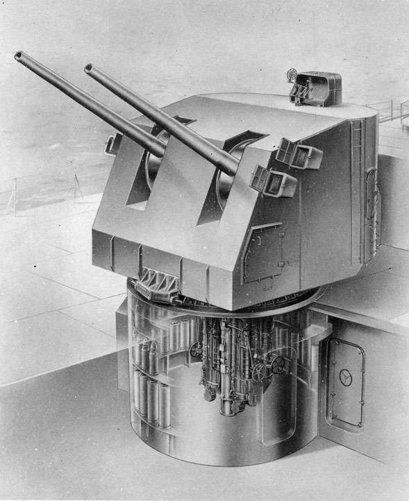
Frontispiece. 5. inch 38-caliber Twin Mount. Installed Arrangement.
|
|
