C.F. 'O' Class Submarines - Tanks, describes the tanks of the Oberon class submarines.
In this online version of the manual we have attempted to keep the flavor of the original layout while taking advantage of the Web's universal accessibility. Different browsers and fonts will cause the text to move, but the text will remain roughly where it is in the original manual. In addition to errors we have attempted to preserve from the original, this text was captured by a combination of optical character recognition and human typist. Each method creates errors that are compounded while encoding for the Web. Please report any typos, or particularly annoying layout issues with the Mail Feedback Form for correction.
A submarine acquires negative buoyancy by flooding sea water into tanks called Main Ballast Tanks. By blowing this water from the tanks, positive buoyancy is restored and the submarine comes to the surface.
Controlled diving and surfacing is made possible by the physical arrangement of these tanks.
Special tanks are provided for rapidly destroying positive buoyancy and to compensate for the compressibility of the hull when undergoing large changes of depth.
Diving trim is maintained by the use of tanks called trim tanks and compensating tanks, and the position of these tanks with respect to the Centre of Buoyancy, establishes the lever arm for maintaining fore-and-aft balance and athwartship stability.
In addition to those above, tanks are provided to carry oil fuel, lubricating oil, fresh and distilled water. Other tanks are fitted for sanitary purposes and to collect bilge water.
3-2
C. F. 'O' CLASS SUBMARINES
CHAPTER 3 - TANKS
PART I - MAIN BALLAST TANKS
3.11 LOCATION OF MBT
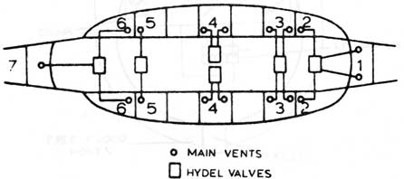
The seven MBTs are fitted around the pressure hull. No. 1 MBT is immediately forward of the pressure hull and No. 7 MBT immediately aft of the pressure hull. All other MBTs are fitted Port and Starboard of the pressure hull.
Numbers 3 to 6 MBT extend into the keel and are divided equally, the Starboard Tank being in the forward part of the keel and the Port Tank in the after section.
(Figure 1)
Location of Main Ballast Tanks
3.12 DESCRIPTION
Sea water enters the Main Ballast Tank through flood ports, called free flood holes, located in the bottom of the tanks near the keel. Large hand operated valves,
called Kingston Valves, are fitted in No. 3 and 5 MBTs instead of free flood holes. Kingston valves are shut when oil fuel is carried in these tanks.
3-3
3.12 DESCRIPTION (CONTD)
All MBTs are fitted with hydraulic vent valves to
allow air to escape from the tanks on diving; these vents are operated from the control room, or locally.
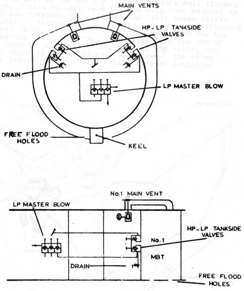
When it is required to bring the submarine to the surface, the water is expelled from the MBTs by blowing H.P. air into the tanks. When sufficient water has been expelled to restore positive buoyancy, the submarine will break surface and the conning tower hatch is opened, then a low pressure air blower is used to bring the submarine to full buoyancy.
(Figure 2)
Typical Sectional MBTs
3-4
3.13 MAIN BALLAST TANK VENTING AND FLOODING
The Main Ballast Tanks are provided with hydraulic operated vent valves. An alternative method of operating these valves is by hand, screwgear with handwheels being employed for Nos. 1 and 7, and pinion and quadrant for Nos. 2 to 6 for operation by ratchet handlevers.
The majority of the main ballast tanks are free-flooding but Nos. 3 and 5 (P & S) are used for carrying oil fuel, are fitted with hand-operated kingstons.
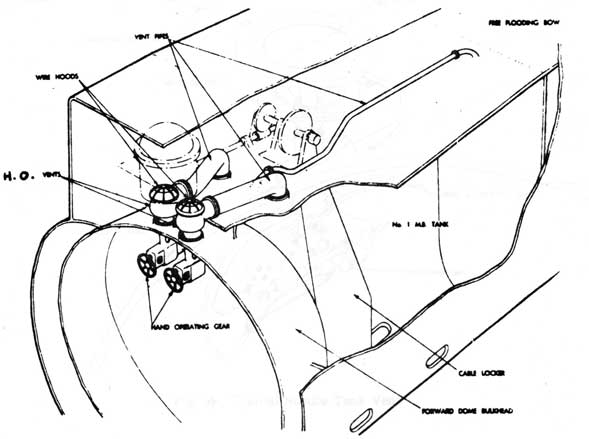
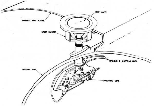
No. 1 Main Ballast Tank has two main vents sited alongside one another on the top of the pressure hull (frames 19-20). No. 7 main ballast tank has one main vent mounted on the top of the pressure hull (frames 114-115); these valves are identical in design. Each of these vents has a fabricated welded steel casing arranged for flange mounting on the top of the pressure hull. External vent pipes from the top of each tank lead air into the casing beneath the valve, the orifice of which is protected by a wire hood. The valve seats on a Dexine ring recessed into a screwed retaining ring.
Fig. 3 No. 1 MB Tank Vent
3-5
3.13 MAIN BALLAST TANK VENTING AND FLOODING (CONTD)
The operating lever is extended to form a toe piece against which a cotter is inserted to lock the valve in its shut position. Steel plate segments, welded to the back of the operating lever, blank off the cotter holes and prevent insertion of the cotter if the valve is not properly shut. When a cotter is not required, it is stowed in a clip provided on the operating gear casing. In addition, a "harbour cotter" is supplied, this cotter being adapted for padlocking to prevent unauthorised withdrawal.
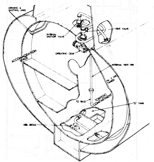
The Main Vent valve assemblies fitted to Nos. 2 to 6 (P and S) Main Ballast tanks are identical. Their constructional details differ from those of Nos. 1 and 7 Main Ballast Tank vent valves in that no external vent pipes are employed. The external hull plating forming the top of each saddle tank is pierced and stiffened with a steel pad welded to the underside of the plating. Within the main ballast tank, a spider bracket is fitted, the top flanged face of which is secured to the pad by countersunk screws.
Fig. 4. Typical Saddle Tank Vent
3-6
3.13 MAIN BALLAST TANK VENTING AND FLOODING (CONTD)
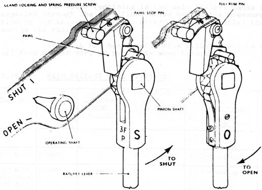
To obviate the possibility of the valve falling when it is being shut by hand, a spring-loaded pawl engages the ratchet wheel of the handlever. When shut, the valve is cottered to enable the ratchet lever to be reversed for opening, an enlarged diameter on one side of the ratchet moving the pawl out of engagement.
Electric switches transmit the "open" and "shut" positions of the vent valves to the Control Room.
(Figure 5)
Ratchet Hand Levers
3-7
3.14 MAIN BALLAST TANK BLOWING ARRANGEMENTS
To surface the submarine, high pressure air is blown into the main ballast tanks through the H.P. tankside valves. Since the main vents are shut, the air cannot escape. It forces the water downwards and out through the free flood holes. The submarine becomes positively buoyant and rises to the surface.
As soon as the submarine surfaces and has sufficient buoyancy to remain on the surface, the H.P. air supply to the main ballast tanks is shut off. Thus only a small part of the H.P. air available is used.
The water remaining in the main ballast tanks is then expelled through the free flood holes by the low pressure (L.P.) blowing system. When all the water has been expelled the submarine has Full Buoyancy.
Number 4 MBT has a split blow allowing air to be shut off from either Port or Stbd side when blowing.
3.15 MAIN BALLAST TANK FITTINGS
TANK NO.
10 in. MAIN VENT
26 in. KINGSTON (HAND OPERATED)
FREE-FLOOD HOLES (15in.x24in.)
DOORS a. MANHOLE (16in.x12in.) b. INSPECTION (IN KEEL)
BLOW VALVE (HP-LP)
1
2
4
a. 1 (top)
HP & LP
2(P & S)
1 each
2 each
a. 1 each(top)
HP & LP ea.
3(P & S)br>(External Oil Fuel)
2 each
1 each
a. 1 each(top) b. 2 each
LP ea.
4(P & S)
2 each
3 each
a. 1 each(top) b. 1 each
HP & LP ea. Split HP Blow
5(P & S) (External Oil Fuel)
1 each
1 each
a. 1 each(top) b. 1 each
LP ea.
6(P & S)
1 each
2 each
a. 1 each(top) b. 1 each
HP & LP ea.
7
1
2
a. 1 (port side) also 2-12 in. x 9 in. access to aft tube fittings
HP & LP
3-8
C. F. 'O' CLASS SUBMARINES
CHAPTER 3 - TANKS
PART 2 - 'Q', D AND O TANKS
3.21 'Q' TANK LOCATION AND FUNCTION
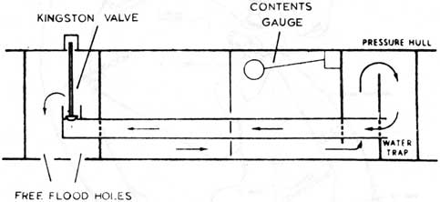
'Q' tank occupies space within the forward section of the keel, which is constructed of 1 1/4 in. thick 'S' quality steel. Two baffle plates fitted near its forward end form a water trap, and a pipe from the Kingston is led to the
trap. This arrangement ensures that the trap will remain full of water until the main part of the tank is blown empty, thus reducing the possibility of air escaping through the Kingston.
Access to the tank is through a manhole on its starboard side, and to the water trap by portable sections in the baffle plates.
(Figure 6)
'Q' Tank
Showing Water Trap
3-9
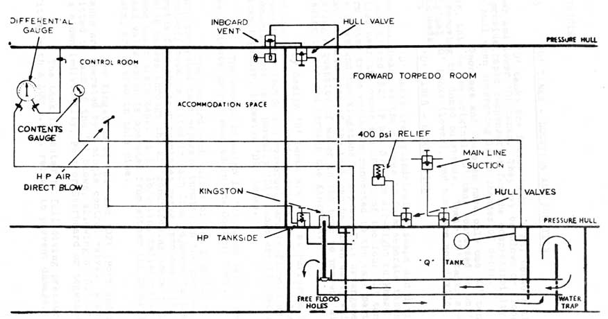
3.22 'Q' TANK - DESCRIPTION
The fittings for operating the tank are, an 8 in. two-position Kingston and a 3 in. inboard vent both hydraulic operated, an H.P. blow, 400 lb/sq.in. relief valve, contents gauge, differential pressure gauge and main line suction valve.
The hydraulic operated inboard vent valve is mounted on the top of the pressure hull and is connected to the tank by a pipe which passes round the hull inside No. 3 main tank (S). The vent pipe from the valve passes inboard through the pressure hull to a hand operated valve and thence to the A.I.V. tank via a tundish.
Owing to the length of the tank the contents gauge reading can only be taken as a guide as any angle on the submarine will affect the level of the contents gauge float.
Before subjecting 'Q' tank to its test pressure of 400 lb/sq.in., its Kingston must be shored up or clamped.
Fig. 7. "Q" Tank Vent
3-10
(Figure 8)
'Q' Tank Fittings
3-11
3.23 'D' TANKS - LOCATION AND FUNCTION
'D' tanks are fitted in No. 4 MBT between the upper and lower 'O' tanks. They may be blown or flooded to provide rapid compensation for the compressibility of the hull when undergoing large changes of depth.
Onondaga and Okanagan have only one 'O' tank each side, this is the original 'D' tank converted to an 'O' tank by removing the domed bulkheads. Their 'D' tanks are the original 'O' tanks (lower), and they are not divided by domed bulkheads.
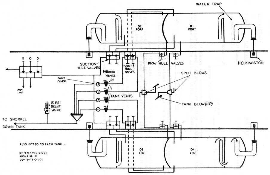
3.24 'D' TANKS - DESCRIPTION
'D' tanks are cylindrical in shape and divided by
domed bulkheads at the centres to form separate tanks, 'D1'
(P and S) and 'D2' (P and S). An air-tight bulkhead is
fitted near the outer end of each of the four 'D' tanks to
form water traps which are connected to the main parts of
the tanks and the Kingstons by pipes. This arrangement ensures
that the main part of the tank can be blown empty while
leaving a quantity of water in the trap to prevent air
passing to the sea through the Kingston.
By design 'D' tanks are full at Periscope Depth and are blown when at various depths to allow for the compressibility factor and conversely are re-flooded as the submarine ascends. Normally 'D1' tanks are flooded and blown together, likewise 'D2' tanks.
The amount of water in 'D' tanks can be read from the contents gauges mounted in the Control Room.
The inboard vent valves of the four 'D' tanks are each connected to a separate tundish in the control room. A shut-off cock is fitted in each line adjacent to its tundish. Drains from the four tundishes merge into one 2 in. bore pipe which passes through the air conditioning space to the engine room snort drain tank. A 15 lb/sq.in. relief valve and a bulkhead valve which is operated from either the Control or Engine Room, are fitted in this pipe.
The Kingstons of 'D1' and 'D2' (Port and Starboard) tanks are operated by a single control valve. A split blow is fitted to each of the 'D' blows, allowing a 'D1' or 'D2' to be blown individually, Port or Starboard or together in pairs.
The tank is tested to full diving pressure and is fitted with a 400 p.s.i. relief to prevent damage.
3-12
(Figure 9)
'(D)' Tank Fittings
3-13
3.25 'O' TANKS - LOCATION AND FUNCTION
'O' tanks are located outside the pressure hull in No. 4 MBT.
(Note - 'Ojibwa' alone has 4 'O' tanks, 2 each side; other C.A.F 'O' class submarines have only one 'O' tank each side, located above 'D' tank).
'O' tanks are connected to the Trim System and are primarily used for adjusting bodily weight; athwartships trim can also be altered using these tanks.
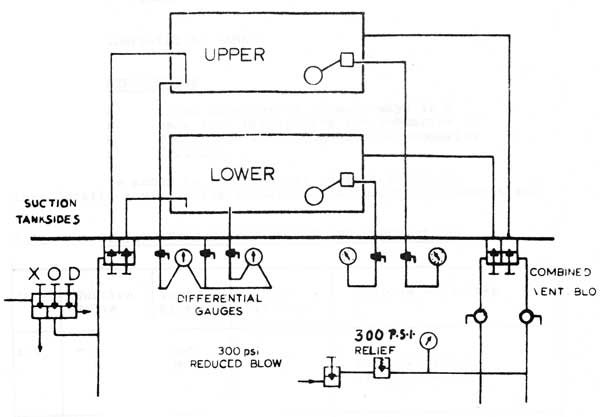
3.26 'O' TANKS - DESCRIPTION
'O' tanks are cylindrical in shape, but unlike 'D' tanks are not sub divided by bulkheads. The tanks are tested to full diving pressure.
Each 'O' tank is fitted with a Trim Line suction, this valve, controlled manually from within the submarine, is used to flood or pump out the tanks in conjunction with the Trim System.
A combined vent and blow system is fitted to allow the tanks to be vented inboard and also may be used as an alternate method to transfer water to sea or from side to side.
The contents of 'O' tanks are read off the Contents Gauges in the Control Room.
3-14
3.25 'O' TANKS - LOCATION AND FUNCTION
(Figure 10)
Typical 'O' Tanks (Ojibwa)
X = Main Line/Trim Line Cross Connection
O = 'O' Tanks Master Suction
D = 'D, Tanks Master Suction
3-15
C. F. 'O' CLASS SUBMARINES
CHAPTER 3 - TANKS
PART 3 - COMPENSATING TANKS
3.31 INTRODUCTION
Compensating tanks serve in many ways in a submarine to the same end; maintaining the submarine in trim. These tanks are located throughout the submarine and have various fittings.
The annex to this chapter gives a table of tank locations within the submarine and individual capacities.
3.32 COMPENSATING TANK FITTINGS AND DESCRIPTION
Tank
Suction Valve
Vent/ Blow
Other Fittings
Purpose - Remarks
AIV
Main Line
Open Top
-
For use with torpedo Air Discharge
FWD TOT
Main Line (P and S)
Comb- ined Vent/ Blows Top S 1
-
Tank split P and S used to blow water to torpedo tubes and receive water from tubes
FWD TRIM
Main and Trim Lines
Local Vents (2)
-
Part of Trim System
'M'
Main Line (P and S)
Local Vents
-
Split Tank
3-16
3.32 COMPENSATING TANK FITTINGS AND DESCRIPTION (CONTD)
'R'
Main Line
Local Vent
Contents Gauge
To receive snorkel mast drain water
'W'
Main Line
Comb- ined vent/ blow
HP Air Compressor cooling lines
Can be used with reduced blow to supply cooling water to HP air compressor
AFT TRIM
Main Trim Lines
Local vent
-
Part of trim system
'COT'
Main Line
Comb- ined vent/ blow
-
Operating tank for after tubes. (as Fwd TOT)
3-17
C. F. 'O' CLASS SUBMARINES
CHAPTER 3 - TANKS
PART 4 - FRESH AND DISTILLED WATER TANKS
3.41 INTRODUCTION
There are six domestic fresh water tanks' one engine fresh water tank and two distilled tanks.
Water pressure to all services is maintained by putting air pressure into the tank in use, with the exception of the engine fresh water tank which is fitted with a hand pump.
3.42 TANKS AND FITTINGS
TANK
COMBINED VENT AND BLOW
FILLING AND SERVICE PIPE
REMARKS
No. 1 F.W.
Inboard vent only
Yes
Port side under No. 1 battery tank.
No. 2 F.W.
Inboard vent only
No
Port side under No. 1 battery tank Common with No. 1 F.W. tank via a syphon pipe.
No. 3 F.W.
Yes (10 lb/sq.in.)
No
Stbd. side under No. 1 battery tank. Common with No. 2 F.W. tank via a syphon pipe.
No. 4 F.W.
Inboard vent only
Yes
Port side under No. 2 battery tank.
No. 5 F.W.
Yes (10 lb/sq.in.)
No
Stbd. side under No. 2 battery tank Common with No. 4 F.W. tank via a syphon pipe.
No. 6 F.W.
Yes (10 lb/sq.in.)
Yes
Stbd. side under engine and motor rooms.
3-18
3.42 TANKS AND FITTINGS (CONTD)
TANK
COMBINED VENT AND BLOW
FILLING AND SERVICE PIPE
REMARKS
No. 1 D.W.
Yes (10 lb/sq.in.)
Yes
Stbd. side under No. 1 battery tank
No. 2 D.W.
Yes (10 lb/sq.in.)
---
Known as 'distiller- made' tank. Directly aft of engine F.W. tank.
Engine F.W.
No
---
Stbd. side forward end of engine room. Used to replenish and drain down engine F.W. circulating system.
Each tank is provided with a dip rod.
3-19
C. F. 'O' CLASS SUBMARINES
CHAPTER 3 - TANKS
PART 5 - OIL AND FUEL TANKS
3.51 INTRODUCTION
This part serves to show the location of these tanks, their operation is covered in detail in other sections.
3.52 FUEL OIL TANKS
Oil Fuel is stored in one internal, eight external and Nos. 3 and 5 (P and S) main ballast tanks. The external tank Nos. 1 and 2 (P and S) between No. 4 and 5 main ballast tanks. The internal tank is sited below the auxiliary machinery space and is provided with a wash bulkhead at the middle line. Further details of these tanks are given in Part 8 dealing with the fuel system.
3.53 LUBRICATING OIL STORAGE TANKS
Lubricating oil is stored in two reserve lubricating oil tanks (P and S) built on either side of a drain oil tank constructed in the top of the reserve lubricating oil tanks. The drain oil tank collects oil from the generating engine sumps. Each tank is fitted with a combined vent and blow (10 lb/sq.in.) and a dip rod.
3.54 HYDRAULIC OIL TANKS
One storage, one replenishing (connected to an air boost space) and three 3-gallon hand pump replenishing tanks are provided. The main replenishing tank is sited in the auxiliary machinery space and the storage tank is constructed in the engine room air space.
The hand pump replenishing tanks are fitted in the torpedo, engine room and after compartments.
3-20
C. F. 'O' CLASS SUBMARINES
CHAPTER 3 - TANKS
PART 6 - MISCELLANEOUS TANKS AND COMPARTMENTS
3.61 SLOP DRAIN AND SEWAGE TANKS
A. A main slop drain tank to take drains from washbasins and bathrooms.
B. A sewage tank to take head drains. This and the main slop drain tank are emptied by blowing to sea through its own S.D.N.R. flap valve and single faced hull sluice valve. Common to each is a (50 lb/sq.in.) blow and a combined inboard and outboard vent.
C. A Ward Room slop drain tank is sited port side of the accommodation space and takes the drains from the C.O.'s washbasin and Ward Room pantry, its fittings are a combined vent and blow (50 lb/sq.in.), a S.D.N.R. flap valve and a single faced hull sluice valve.
D. A slop drain tank for garbage ejector space and sink is sited on the port side of the accommodation space and is fitted with a combined vent and blow (5O lb/sq.in.), a S.D.N.R. valve and a single
faced hull sluice valve.
E. A slop drain tank to take drains from the after sink is constructed in the after trim tank and is emptied in a similar manner to (e) and (f).
In Onondaga and Okanagan tanks (A) and (B) form a single tank called the sanitary tank.
3.62 SONAR
A. A sonar directing gear chamber of circular section with domed ends fitted with a 21 in. dia. W.T. hatch is built under the top of the superstructure towards the bow between frames 2-9. It is tested to 400 lb/sq.in. A drain from the after end of the chamber is led inside the pressure hull to the nearest bilge. The chamber houses directing gear Type 187, and is fitted with a 1O lb blow to enable it to be
tested prior to proceeding to sea. The blow is combined with a 9.375 in. inboard vent.
3-21
3.62 SONAR (CONTD)
A. (contd)
A dome is fitted immediately over the Sonar
chamber to protect the transducer.
B. A Sonar compartment is constructed beneath the Forward Torpedo Room flat, the trunk extending through the A.I.V. tank. It is closed by a splash-tight cover. The trunk extends through the pressure hull, and is sealed by a watertight cover. The trunk houses a Sonar hull outfit No. 3, the cage of which is lowered into a recess within the keel.
3.63 MISCELLANEOUS
A. A snorkel drain tank is sited in the engine room port side forward. It is baffled to separate water from the induction air and is provided with a contents gauge and main and oily bilge line connections.
B. An oily bilge tank is constructed below the hydraulic air boost space and is fitted with a dip rod and oily bilge pump suction. Into it are led the after engine room bilge pipe and vents from the engine salt water circulating pumps.
C. Other tanks external to the pressure hull are two engine exhaust tanks (P and S) which are mounted aft on top of the pressure hull beneath the superstructure.
3-22
C. F. 'O' CLASS SUBMARINES
TANK LOCATIONS, TEST PRESSURES AND CAPACITIES
TANK
FRAMES
TEST PRESSURE
CAPACITY (gallons)
A = AIR Initial
W = WATER Final
No. 1 MBT
9-18
20(W)
20(A)
10687
A.I.V. tank
18-22 1/2
Filled with water
None
1875
T.O.T. (P)
22 1/2-27 1/2
100(W)
100(A)
2400
T.O.T. (S)
22 1/2-27 1/2
100(W)
100(A)
2375
Trim tank forward(P)
27 1/2-32
70(W)
70(A)
2175
Trim tank forward(S)
27 1/2-32
70(W)
70(A)
2179
No. 1 battery tank
34-47
5(A)
5(A)
No. 1 F.W. tank
34-42(P)
15(W)
15(A)
2040
No. 1 distilled water tank
34-42(S)
15(W)
15(A)
1925
No. 2 F.W. tank
42-47
50(w)
50(A)
1200
No. 3 F.W. tank
42-47
50(W)
50(A)
1245
No. 2 battery tank
49-62
5(A)
5(A)
Cold and cool rooms
72 1/2-77(S)
5(A)
5(A)
No. 4 F.W. tank
49-53(S)
15(W)
15(A)
1035
No. 5 F.W. tank
49-53(P)
15(W)
15(A)
1035
'M' comp. tank (P)
53-62
50(W)
50(A)
2190
'M' comp. tank (S)
53-62
50(W)
50(A)
2185
Hyd-oil storage tank
62-63(P)
15(W)
15(A)
250
Internal O.F. tank
62-68
50(W)
50(A)
2776
'R' comp. tank
68-75
50(W)
50(A)
2889
Sewage tank
75-76(S)
50(W)
50(A)
332
Slop drain tank
76-77(S)
50(W)
50(A)
375
Hyd-oil replenishing tank
67-68
20(W)
20(A)
100
Snorkel drain tank
77-81(P)
Fill with water
None
717
Engine F.W. tank
77-80
15 (W)
15(A)
471
Distiller made F.W. tank
80-81
15(W)
15(A)
154
Drain oil tank
81-84
15(F.W.)
15(A)
780
Reserve L.O. tank(P)
81-86
15(F.W.)
15(A)
2603
Reserve L.O. tank(S)
81-86
15(F.W.)
15(A)
2200
Hyd/air boost space
86-87
20(W)
20(A)
'W' comp. tank
87-97
50(W)
50(A)
3025
No. 6 F.W. tank
87-97
50(W)
50(A)
2775
3-23
TANK LOCATIONS, TEST PRESSURES AND CAPACITIES (CONTD)
TANK
FRAMES
TEST PRESSURE
CAPACITY (gallons)
A = AIR Initial
W = WATER Final
After trimming tank
109-113 1/2
70(W)
70(A)
2400
Countermeasure operating tank
113 1/2-116
100(W)
100(A)
979
No. 7 M.B. tank
116-122
20(W)
20(A)
2441
'Q' tank
261/5-33
400(W)
20(A)
817
No. 2 MBT (P)
22-32
20(W)
20(A)
4770
No. 2 MBT (S)
22-32
20(W)
20(A)
4770
No. 3 MBT (P)
32-42
20(W)
20(A)
9837
No. 3 MBT (S)
32-42
20(W)
20(A)
9837
No. 1 ext OFT (P)
42-50
20(W)
20(A)
10145
No. 1 ext OFT (S)
42-50
20(W)
20(A)
10145
No. 2 ext OFT (P)
50-56
20(W)
20(A)
8026
No. 2 ext OFT (S)
50-56
20(W)
20(A)
8026
No. 4 MBT (P)
56-67
20(W)
20(A)
11780
No. 4 MBT (S)
56-67
20(W)
20(A)
11599
No. 3 ext OFT (P)
67-74
20(W)
20(A)
8385
No. 3 ext OFT (S)
67-74
20(w)
20(A)
8270
No. 4 ext OFT (P)
74-80
20(W)
20(A)
6340
No. 4 ext OFT (S)
74-80
20(W)
20(A)
6261
No. 5 MBT (P)
80-88
20(W)
20(A)
7358
No. 5 MBT (S)
80-88
20(W)
20(A)
7358
No. 6 MBT (P)
88-94A
20(W)
20(A)
4235
No. 6 MBT (S)
88-94A
20(W)
20(A)
4107
'O' tank No. 1 (upper) (P)
58A-65
400(W)
20(A)
636
'O' tank No. 1 (upper) (S)
58A-65
400(w)
20(A)
636
'D' tank No. 1 (P)
58A-62
400(W)
20(A)
355
'D' tank No. 1 (S)
58A-62
400(w)
20(A)
355
'D' tank No. 2 (P)
62-65
400(w)
20(A)
302
'D' tank No. 2 (S)
62-65
400(W)
20(A)
302
'O' tank No. 2 (lower) (P)
58A-65
400(W)
20(A)
636
'C' tank No. 2 (lower) (S)
58A-65
400(W)
20(A)
636
Sonar chamber
2-9
400(W)
20(A)
985
Conning tower
60-62
135(W)
20(A)
Engine exhaust tanks (P) (S)
86-87 1/3
None
None
3-24
Large Plate on Separate Page
HULL AND TANKS
"O" CLASS
OJIBWA ONLY PLATE 1
3-25
Large Plate on Separate Page
HULL AND TANKS
"O" CLASS
ONONDAGA & OKANAGAN PLATE 2