C.F. 'O' Class Submarines - Induction and Exhaust System, describes the intake of air and exhaust through snorkel and mufflers of the Oberon class submarines.
In this online version of the manual we have attempted to keep the flavor of the original layout while taking advantage of the Web's universal accessibility. Different browsers and fonts will cause the text to move, but the text will remain roughly where it is in the original manual. In addition to errors we have attempted to preserve from the original, this text was captured by a combination of optical character recognition and human typist. Each method creates errors that are compounded while encoding for the Web. Please report any typos, or particularly annoying layout issues with the Mail Feedback Form for correction.
(a) To supply air to the diesel-generators when running at Periscope Depth.
(b) To conduct the engine exhaust to the surface with minimum risk of flooding the engine.
(c) The system must be capable of quick shut-down in the event of detection.
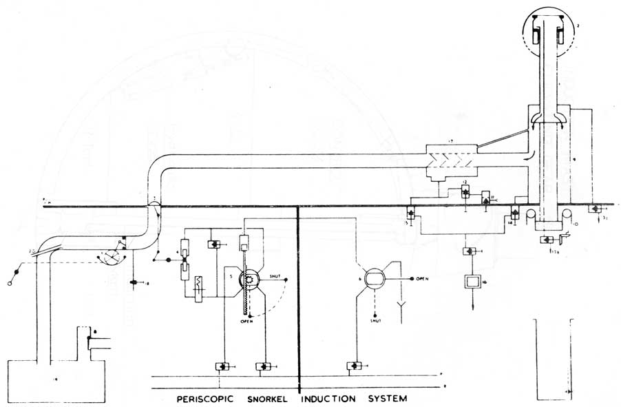
8.02 SNORKEL INDUCTION SYSTEM
Air enters the S/M via a periscopic mast fitted
with a float controlled head valve. The air passes through
a Helix Drier & external pipe, to the Snorkel Induction
Hull Valve, from where it passes through the pressure hull
into the Snorkel Drain Tank via a hand-operated Emergency
Flap Valve. The final separation of the entrained water occurs
in the Snorkel Drain Tank which can be periodically pumped out.
The air vents from the top of the tank into the atmosphere of
the submarine. (Figure 2)
With the mast partly raised, and the submarine at periscope depth (i.e. head valve shut) the external system can be drained into an internal tank by operating the Flood and Drain Valve, Snorkel Drains One and Two, and the mast vents. Thus the system can be prepared for use before the mast is fully raised.
The Induction Hull Valve can be operated from the Engine Room by hydraulic pressure or by hand. It can also be shut by hydraulic pressure from the Control Room in an emergency.
The Emergency Flap Valve is spring loaded and balanced and will shut if there is a rush of water down the mast (i.e. head valve stuck open). Should this fail it can be shut by hand either at the valve or at the engine platform.
8-2
SNORKEL INDUCTION SYSTEM
8-3
Fig 2
8-4
8-5
8.03 OPERATION
On preparing for snorkelling, the induction system is drained down with the mast still below the surface. This is done by the Control Room Watchkeepers. At the same time the engines are prepared.
On starting the main engines the Induction Hull Valve is opened, and the mast fully raised.
To stop snorkelling, the Induction Hull Valve is shut, engines stopped, snorkel drains shut and the mast lowered. The external induction system is then flooded up (Flood and Drain Valve and Vents), and water is pumped from 'R' tank to compensate.
Note. In case the mast is not flooded up before the S/M goes deep the head valve is so constructed that it will lose buoyancy at 120 ft (keel depth), drop open and flood the mast.
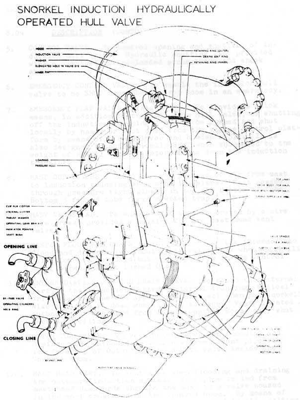
8.04 DESCRIPTION (Figure 2)
Object. To provide air for the engines and for ventilation
purposes when at periscope depth.
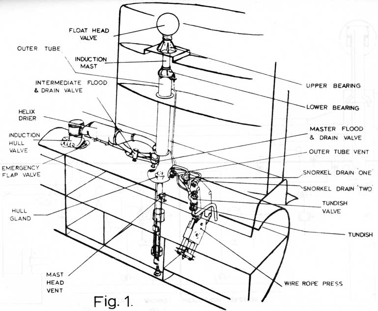
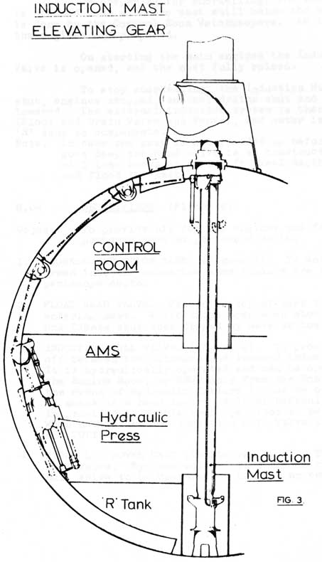
1. SNORKEL INDUCTION MAST. (Figure 3). To enable air to be drawn into the submarine when engines are running at periscope depth.
2. FLOAT HEAD VALVE. Fitted to top of mast to prevent water entering mast. Valve drops open when above surface of sea, and floats shut when dipped by wave or loss of depth.
3. INDUCTION HULL VALVE. (Figure 4). To provide a hull shut
off between the outboard and inboard induction trunkings.
It is hydraulically operated and can be opened and shut from
the Engine Room, or SHUT only from the Control Room. In
the event of hydraulic failure it can be opened and shut
by means of a hand lever. A local hydraulic by-pass valve
is provided to enable hand operation to be carried out.
When not in use the Induction Hull Valve is kept SHUT
and COTTERED.
4. HYDRAULIC POWER UNIT (Double ram type). To open and shut hull valve. By-pass valve fitted across rams to enable hull valve to be operated by hand in an emergency.
8-6
FIG.4
8-7
8.04 DESCRIPTION (CONTD)
5. CONTROL VALVE. To control opening and shutting of induction hull valve. Hydraulic shutting line provided with a combined spring-loaded accumulator and shook absorber.
6. EMERGENCY CONTROL VALVE. To enable the induction hull
valve to be SHUT from the Control Room in an emergency.
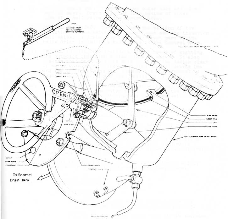
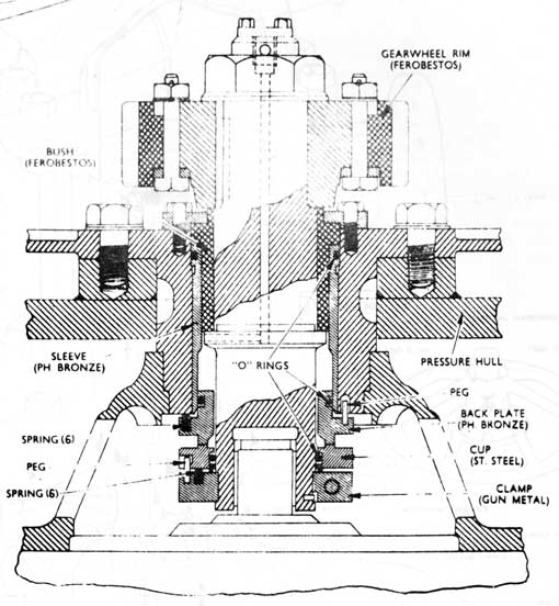
7. EMERGENCY FLAP VALVE. (Figure 9). To provide a quick
means, in addition to the induction hull valve, of shutting off the induction trunking. It can be opened and shut locally by hand, or Shut only from the engine control platform by means of a hand lever and Bowden cable. It is also designed to automatically SHUT when subjected to the weight of a full bore of water coming down the induction trunking.
8. MAST OUTER TUBE. To allow free passage of air from mast
to induction trunking when mast is raised. Mast passes through pressure tight glands in top and bottom of tube. Bottom 3 ft. of tube forms a water trap.
9. MAST CROSSHEAD. To enable mast to be operated by a wire
rove press; provides a housing for the mast head vent valve.
10. MASTER FLOOD AND DRAIN VALVE. To back up the intermediate flood and drain valve should this valve leak when snorkelling Valve located outboard but operated from inside Control Room; normally kept lashed OPEN.
11. INTERMEDIATE FLOOD AND DRAIN VALVE. To flood the external part of the induction system (external trunking, helical drier, outer tube and upper half of mast) when not snorkelling. Also to drain it down when on the surface. Valve located outboard but operated from inside Control Room; only shut when snorkelling.
12a. OUTER TUBE VENT. To vent outer tube when flooding and draining the outboard induction system. Vent pipe is led from top of Outer Tube to a hull valve inside the Control Room.
12b. MAST HEAD VENT. To vent mast when flooding and draining the outboard induction system. Vent pipe is led from mast head downwards through the mast to a valve housed in the mast crosshead in the Control Room. By means of rod gearing the vent valve can be orated in all positions of the mast.
8-8
SNORKEL INDUCTION AUTOMATIC FLAP VALVE
Fig. 5
8-9
8.04 DESCRIPTION (CONTD)
13. SNORKEL DRAIN ONE. To drain down outer tube and upper part of mast. Drain pipe led from bottom of outer tube of a hull valve in the Control Room.
14. SNORKEL DRAIN TWO. To drain down the section of the induction system between the outer tube and the induction hull valve. A drain pipe from the lowest part of the helix drier is led to a hull valve in the Control Room.
15. SNORKEL TUNDISH. To provide a simple means of sighting the outboard induction system clear of water. It also ensures that the O.O.W. is able to sight the system clear of water when snorkelling, water from snorkel drains One and Two enters the tundish through a common snorkel tundish drain valve, and then passes to 'R' tank.
16. HELICAL DRIER. To remove any water which may have passed with the air from the outer tube. It gives the incoming air a swirling motion causing any entrained water to be separated by the centrifugal action.
17. DRAIN COCK. To check inboard trunking clear of water before opening emergency flap valve.
18. SNORKEL DRAIN TANK. To collect any water not removed by helical drier. It is sited low down in the Engine Room and forms the terminus of the induction trunking. It is provided with a dip rod, and main and oily bilge line suction valves; it also has a large opening in the top, protected by wire mesh, to allow an unrestricted flow of air into the Engine Room.
19. FLOODING INDICATOR PIPE. To give indication if a full bore of water is passing the emergency flap valve.
8.05 EXHAUST SYSTEMS
A. Requirements
(1) To conduct the engine exhaust from the submarine both surfaced or snorkelling.
(2) To Be capable of quick shut off to minimise
risk or flooding engine.
(3) To provide silencing when surface running.
8-10
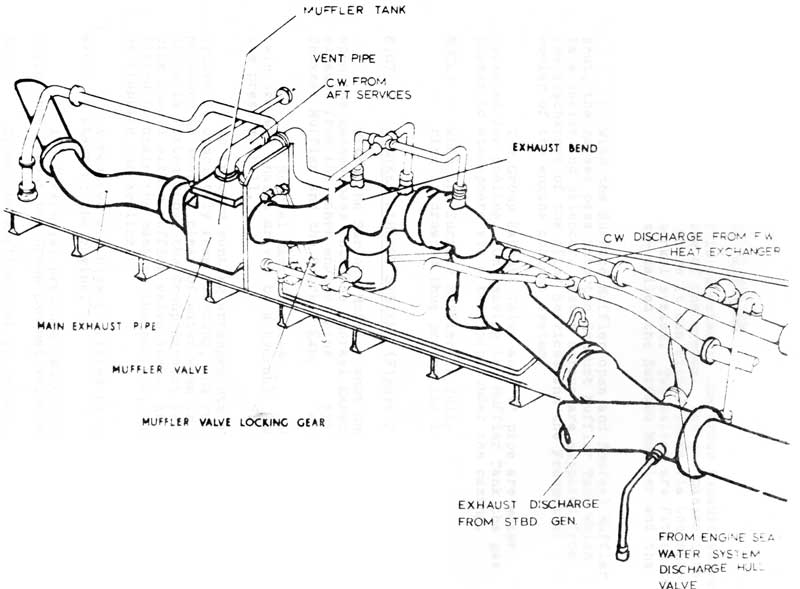
ENGINE EXHAUST SYSTEM - EXTERNAL
Fig 6
8-11
8.06 SURFACE EXHAUST SYSTEM
Exhaust gas is directed to the Group Exhaust Valve which is the hull valve of the system. The gas passes into an external 'T' pipe where it can either leave via the surface system or the snorkel system. Two valves are fitted to isolate either system - called the Surface Muffler and the Snorkel Muffler.
With the Surface Muffler open and Snorkel Muffler shut, the gasses pass into the Exhaust Muffler Tank which is a cooler and silencer. Water sprays are supplied from the discharges of the After Services and the Freshwater cooler of the engine coolant system.
The Group Exhaust Valve and 'T' pipe are water jacketed for cooling. On leaving the Muffler Tank the gas passes to atmosphere via a tail pipe under the casing.
NOTE: When the Surface Muffler is fully open, its seat
ring is drowned thus protecting it from gas damage.
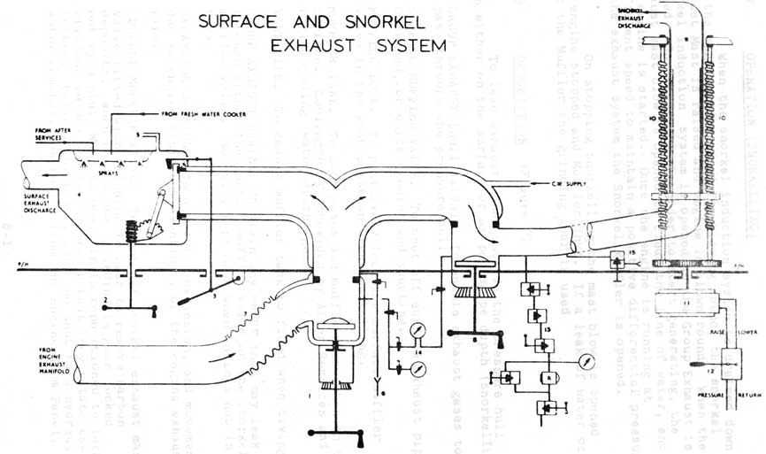
8.07 SNORKEL EXHAUST SYSTEM (Figure 7)
With the Surface Muffler shut and Snorkel Muffler open, the gasses pass into the Snorkel Exhaust Mast. The exhaust from the other engine joins the system between the Snorkel Muffler and the Snorkel Exhaust Mast.
The Snorkel Mast is telescopic, and is operated by twin screwed shafts driven by a hydraulic motor sited inside the pressure hull.
No inboard venting arrangements are required as the system is completely free flooding, and relies on the exhaust pressure to keep it clear of water when in use. An inboard drain is fitted above the Group Exhaust Valve to drain the 'T' pipe should either muffler valve leak. An outboard drain is fitted to drain the mast on the surface, and to assist flooding on stopping snorkelling.
A reduced air blow is fitted to clear the mast of water on starting the engine.
A differential pressure gauge shows the pressure difference across the Group Exhaust Valve and Snorkel Muffler.
Since the Muffler seat is in the gas stream when open, it has a metallic seat. Therefore grinding arrangements are incorporated in the construction of the valve.
8-12
SURFACE AND SNORKEL EXHAUST SYSTEM
Fig 7
8-13
8.08 OPERATION (SNORKELLING)
When the snorkel induction system is drained down, and the engine is prepared for blowing round, the snorkel Exhaust Mast is raised and engine is blown round. When the snorkel induction system is opened up the Group Exhaust is opened. On receipt of the order to start generating, the exhaust mast blow is opened to clear the line of water, and the engine is started. Once the engine is running at sufficient speed to maintain a positive differential pressure in the exhaust system the Snorkel Muffler is opened.
On stopping snorkelling the mast blow is opened up, engine stopped and Muffler shut. If a leak of water occurs past the Muffler the grinding gear is used.
8.09 DESCRIPTION (Figure 7)
To lead exhaust gases outside the pressure hull when either on the surface or at periscope depth (snorkelling).
1. GROUP EXHAUST (Hull Valve). To enable exhaust gases to pass through the pressure hull.
2. SURFACE MUFFLER VALVE. To shut off surface exhaust pipe. Designed for quick opening and shutting.
3. MUFFLER LOCK. To positively lock the surface muffler valve in the shut position when snorkelling.
4. MUFFLER TANK. To cool gases and muffle noise when on the surface. Cooling water provided by After Services and Engine cooling water discharges.
5. VENT PIPE. To enable muffler tank to flood when diving.
6. GROUP EXHAUST DRAIN. To drain any water that may leak through either the surface muffler valve or the snorkel murder valve. Normally kept open when engines not in use.
7. EXPANSION SECTION. To allow tor expansion, and movement due to engine resilient mountings, of the engine exhaust
pipe.
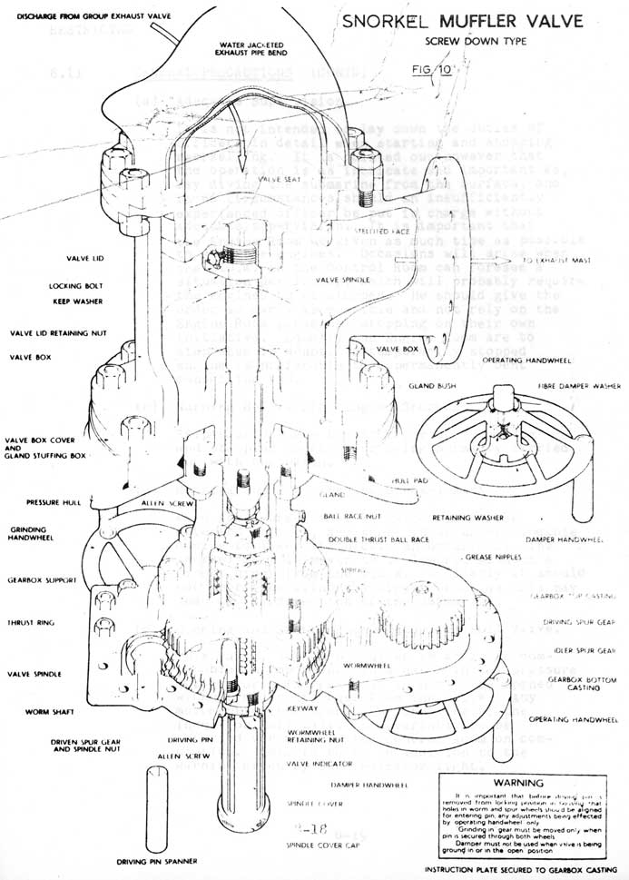
8. SNORKEL MUFFLER VALVE. To shut off snorkel exhaust mast. Valve fitted with grinding in gear to remove carbon deposits. When not in use grinding in gear locked out by a pin. When in use, pin is repositioned to lock
grinding in and shifting gears so that they rotate together.
Valve is opened by hand and shut by a hydraulic
motor remotely controlled from the Engine Room Panel.
8-14
8.09 DESCRIPTION (CONTD)
9. SNORKEL EXHAUST MAST. To enable exhaust gases to be discharged a few feet below the surface of the sea. (Figure 8)
10. SCREW HOIST. To raise and lower exhaust mast.
11. MAST HYDRAULIC MOTOR. To operate screw hoist.
12. PISTON CONTROL VALVE. To control flow of hydraulic fluid to and from mast motor.
13. SNORKEL EXHAUST BLOW (50 p.s.i.). To expel water from
the snorkel exhaust mast just prior to starting the engines.
14. DIFFERENTIAL GAUGE. To indicate when the mast is clear of water before starting engines.
15. SNORKEL EXHAUST DRAIN. To assist flooding of mast when not in use, also to drain mast when on the surface.
8.10 SNORKELLING HAZARDS
The main hazards when snorkelling are as follows:
(a) It is possible for water to enter through the Induction Hull Valve so rapidly that it may sink the submarine unless immediate corrective action is taken.
(b) If a submarine is taken deep with an engine running, water flooding back through the exhaust can result in damaging the engine beyond repair.
(c) Prolonged subjection to air at pressure below 25 3/4 in. Hg. can produce ill effects among the ship's company through lack of oxygen. It should be noted that this figure corresponds to an oxygen percentage of 18% at normal temperature and pressure.
8.11 GENERAL PRECAUTIONS
The following constitute the main general precautions to avoid accidents when snorkelling.
8-8-15
8.11 GENERAL PRECAUTIONS (CONTD)
(j) Stopping Snorkelling - Danger of Excess Vacuum
A vacuum in the submarine should normally be relieved straight away through the snorkel. When operations do not permit this, the action to be taken is laid down in S.G.M. 205.
(k) Engine Room Personnel
The ideal is for the E.R.A. to remain on the engine starting platform throughout his watch. It is appreciated that in some submarines this is not practical if there is an emergency elsewhere, but it must be impressed on the watch-keepers that their prime duty is the safety of the engines, and any absence from the starting platform must be reduced to a minimum. In rough weather no relaxation of the ideal should be permitted.
8.12 Responsibility for Stopping Snorkelling
(a) Responsibility of the O.O.W.
Ship's orders are to include the following conditions under which he must stop snorkelling.
(i) If at any time he considers that the submarine is not fully under control.
(ii) When the pressure in the submarine persists steadily below 25 3/4 in. Hg. or falls below 22 In. Hg.
(iii) If a continual heavy flow of water is coming down the Snorkel Drain.
(b) Responsibility of the E.R.A. of the Watch.
Ship's orders are to include the following conditions under which the E.R.A. of the watch is
to stop snorkelling on his own initiative:
(i) When a continual heavy inflow of water is coming down the snorkel induction mast.
(ii) When back pressure of more than 8 p.s.i. occurs across the engines
(iii) When a keel depth of 63 ft. is reached
(iv) When a bow down angle of 6° is reached
8-16
Large Plate on Separate Page
SNORKEL EXHAUST MAST SCREW GEAR AND BEARINGS Fig 8.
8-17
FIG. 9. BRADFORD SEAL ASSEMBLY
8-18
8-19
8.11 GENERAL PRECAUTIONS (CONTD)
(a) Adequate Supervision
It is not intended to lay down the duties of Officers in detail when starting and stopping snorkelling. It is pointed out however that the operation is as intricate and important as, say diving the submarine from the surface, and in no circumstances should an insufficiently experienced officer be put in charge without adequate supervision. It is important that the Engine Room be given as much time as possible to stop the engines. Occasions will arise when the O.O.W. in the Control Room can foresee a situation developing, which will probably require the engines to be stopped. He should give the order as early as possible and not rely on the Engine Room personnel stopping on their own initiative. Equally the Engine Room are to stop when in doubt. A temporarily stopped engine is preferable to a permanently bent connecting rod.
(b) Warning Before Starting to Snorkel
Ship's orders are to cater for the starting and stopping snorkelling being normally carried out with one watch.
(c) Raising and Lowering the Snorkel Mast
When the snorkel mast is raised it can be detected or seen, and there is an understandable desire to lower it quickly on occasions. The snorkel mast is never to be lowered without a direct order from the O.O.W. Similarly it should not be raised without a direct order as this may lead to the detection of the submarine.
(d) Opening and Shutting the Induction Hull Valve.
This valve, although smaller in area, is comparable in importance to a hatch in the pressure hull. For this reason it is not to be opened without a direct order from the O.O.W. Any movement either opening or shutting of the Induction Hull Valve is invariably to be
reported verbally to the Control Room on completion. This is to be in addition to the warning given by the indicator light.
8-20
8.11 GENERAL PRECAUTIONS (CONTD)
(e) Checking the Induction Flooding Indicator Drain Pipe
The main indication of water entering through the snorkel mast is the induction flooding indicator drain pipe. When starting snorkelling and at the change of each watch, therefore, the flooding indicator drain pipe is to be checked clear.
(f) Minimum Engine Revolutions to Avoid Flooding Back
Snorkelling trials include trials to determine the minimum revolutions for snorkelling on one or two engines without risk of flooding back through the exhaust. The result of these trials are noted in the Captains Ships Book and the maximum revolutions established are to be inserted in the Ship's Standing Orders for snorkelling.
(g) Stopping Snorkelling
(i) The responsibility for stopping snorkelling
and the limiting conditions are laid down in para. 4 below.
(ii) The standard method for passing the order to stop snorkelling to the Engine Room is by use of the Stop Snorkelling Alarm. NO OTHER METHOD should be used.
(h) Danger of Hydrogen on Breaking the Charge.
If both engines are stopped on breaking the charge and the battery has already reached the gassing point, there is a possibility that a dangerous percentage of hydrogen will build up in the Engine Room. This will be diffused in due course by the ship's ventilation. If however, an engine is started again immediately there is a possibility of a fire or an explosion. Whenever practicable, therefore, the engine should be kept running; if both engines have been stopped, a pause of at least ten minutes should be allowed before re-starting.
8-21
8.12 RESPONSIBILITY FOR STOPPING SNORKELLING (CONTD)
NOTE 1: The main aids to the E.Rm. for deciding whether
a sudden plunge is imminent are the Barometer, the Clinometer and the Depth Gauge; but it must be remembered that these instruments may not necessarily give immediate indication of danger.
NOTE 2: It is important that depth gauges are kept accurate
and pressure tight and are vented from time to time.
8.13 SNORKELLING DRILL
The detailed orders for snorkelling drills are laid
down in Ship's Standing Orders, but the following steps in the drill should not be omitted.
(a) Starting Snorkelling
(i) Order "Stand by to snorkel port/starboard engine". The necessary additional personnel are to close up to ensure adequate supervision is available. Machinery and systems are prepared.
(ii) Order "Raise the Snorkel Induction Mast". (This may be delayed until starting the 1st engine in submarines fitted with periscopic snorkel masts.
(iii) The draining down of the snorkel induction mast i3 to be carried out by direct order to open or shut the valves concerned.
(iv) Concurrently with (iii) the preliminary telegraph orders are to be given.
(v) Order "Open Snorkel Induction Hull Valve" (and rising of snorkel exhaust mast where a telescopic mast is fitted).
(vi) Engine movements are ordered.
(vii) A margin of space should be allowed in 'R' Tank to avoid the risk of damage to the tank in the event of errors in
the operation of the main line.
There should be a margin of at least 300 gal. and, if possible 600 gal. in the tank whist snorkelling.
8-22
8.13 SNORKELLING DRILL (CONTD)
(b) Stopping Snorkelling
(i) Order "Stop Snorkelling" - by use of Stop Snorkelling Alarm.
(ii) The Induction Hull Valve, the Emergency Flap Valve and Snorkel Drain One are to be shut and reported SHUT to the Control Room. (The automatic SHUT/OPEN Induction Hull Valve indicator light must be sighted in a position where it can be seen by the O.O.W. and the rating operating the Snorkel Mast Hydraulic control valve.
(c) Breaking the Vacuum
(i) The draining of the snorkel induction system is to be done by direct order to open or shut the valves concerned, if draining Is required.
(ii) Order "Open snorkel induction hull valve".
(iii) Order "Open Snorkel emergency flap valve".
(iv) Order "Shut induction hull valve and emergency flap valve".
8-23
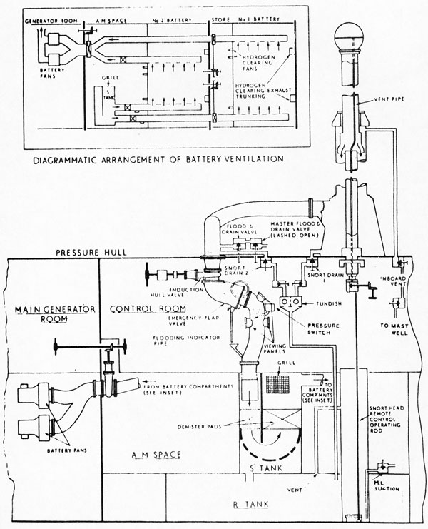
8.14 MODIFIED INDUCTION SYSTEM (Fig. 11)
The modified induction system as fitted to SS 73 and 74 differs from the original system in that:
(a) A helix drier is not fitted.
(b) The induction hull valve is a sluice valve operated by a Deri-Sine Motor and is sited overhead in the Control Room.
(c) The main control valve for the induction hull valve is sited in the Control Room and the emergency control valve in the Main Generator Room.
(d) Snorkel drains 1 and 2 each have a backing up valve.
(e) Three viewing panels are sited on the inboard side of the emergency flap valve.
(f) The flooding indicator pipe is led to a pressure sensitive switch wired to a buzzer and a flashing light in the Control Room.
(g) The inboard trunking terminates in a separation tank ("S" tank) sited in the AOS above "R" tank and any water drains into "A" tank. "R"
vents into the induction mast well.
(h) Air supply to the generating engines is taken from a grill on "S" tank via the ACS. Air -supply to the battery compartments can be taken either from "S" tank or the ACS.
8.15 GROUP EXHAUST VALVE (Power Operated)
The air operated group exhaust valve fitted to SS 73 and 74 has the following advantages:
(a) The bore is increased to 8 inches.
(b) The valve is not in the gas stream when open.
(c) The resistance to shock is increased.
(d) It is controlled from the starting platform.
The valve consists of a double faced sluice valve made up of two lids, working in a body and operated by an external piston through a rack mechanism.
A toggle gear is provided for locking the valve in the shut position, this being operated by an HP piston.
In an emergency both the operating and locking gears can be worked by hand.