C.F. 'O' Class Submarines - Hydraulics Systems, describes the hydraulic systems of the Oberon class submarines.
In this online version of the manual we have attempted to keep the flavor of the original layout while taking advantage of the Web's universal accessibility. Different browsers and fonts will cause the text to move, but the text will remain roughly where it is in the original manual. In addition to errors we have attempted to preserve from the original, this text was captured by a combination of optical character recognition and human typist. Each method creates errors that are compounded while encoding for the Web. Please report any typos, or particularly annoying layout issues with the Mail Feedback Form for correction.
The definition of hydraulics as applied to engineering is the application of pressure to an enclosed or confined liquid to transmit power and the harnessing of this power to do useful work. The submarine application is dependent on Pascal's Law which states that "pressure on any part of a confined liquid is transmitted undiminished on all directions throughout the liquid".
The ideal hydraulic fluid is a light fast flowing lubricating oil that does not freeze or lose its fast flowing ability at low temperatures. It must also afford proper lubrication of the moving parts of the system = 3GP36 Grade 3.
The first submarines depended on the manual efforts of the crew to perform many operations now done by hydraulic power. This was gradually replaced by electrical equipment and in some cases, air or pneumatic power.
The power sources had certain inherent disadvantages which made further development of hydraulic power desirable.
Hand power had the obvious limitation of the physical capacity of the operator, so designers turned to air and electricity. The major disadvantage of air power was its "sponginess" which made accurate control of an operation difficult and uncertain, and a major increase in the storage facilities for HP air would be necessary if an adequate supply was available. HP air compressors require more maintenance than hydraulic pumps and HP and leakage could create a build up of pressure in the submarine.
Electric power has certain disadvantages. Motors generators and controls would be heavy and complex where large amounts of power are required. More highly skilled technicians would be needed, starting, stopping and intermediate control would be difficult when the load is large and precise control necessary. Noise would also be a serious factor when the electric power must be converted to mechanical power through gears, levers, racks and other mechanical agents.
6-2
(Figure 1)
6-3
6.01 INTRODUCTION (CONTD.)
Hydraulic equipment is relatively light and simple in operation, it is self lubricating which reduces wear and corrosion. It is quiet in operation, requires the minimum of attention and maintenance and is extremely reliable.
Instantaneous starting and stopping, with precise intermediate control is easily obtained as can efficient operation of remote equipment whether the operation be continuous or intermediate.
Most of the mechanical equipment in the modern 'O' class submarine is operated by hydraulic power.
6.02 MAIN HYDRAULIC SYSTEM
The system will be dealt with under three main
headings:
A. The Basic Hydraulic System and its build up
B. The Automatic Control System
C. Fittings controlled by the system.
A. BUILD UP OF BASIC HYDRAULIC SYSTEM
Object:
(a) To supply hydraulic pressure to hydraulically operated fittings.
(b) To return all used hydraulic fluid to a replenishing tank for re-use.
Al General Description
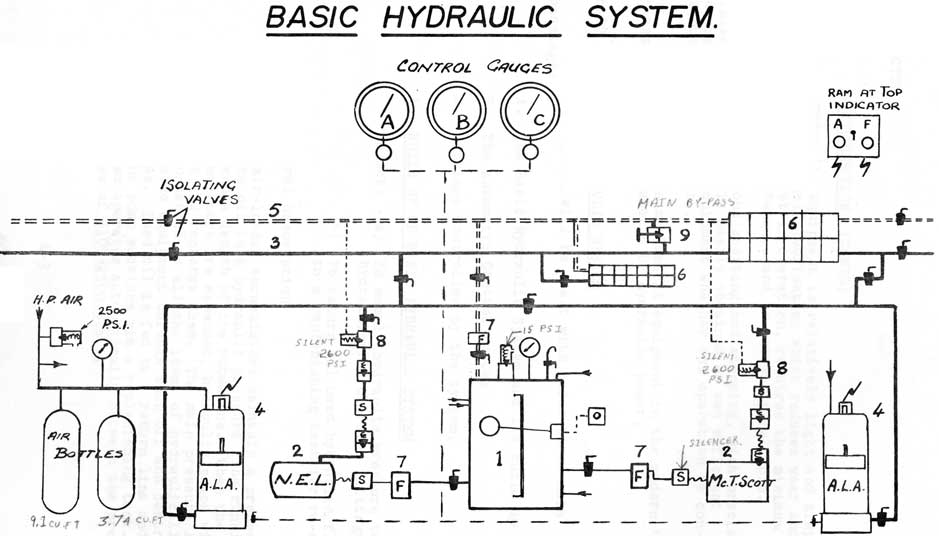
Two air-loaded accumulators maintain a pressure on the oil in a hydraulic pressure line running the whole length of the submarine. When the accumulators are expended, hydraulic pumps will start and recharge them. The main pressure line is connected to all the items of hydraulically operated equipment through shut off and control valves. Used oil is fed to a return line and back to the pump suctions via a replenishing tank. The system operates automatically between the pressure ranges of 2100-2500 p.s.i.
6-4
6-5
6.02 MAIN HYDRAULIC SYSTEM (CONTD.)
A2 Fittings
(1) Replenishing Tank. Sited on the Auxiliary Machinery Space bulkhead. Capacity 100 gal. Supplies oil to suction side of hydraulic pumps. Fittings:
(a) Connection to air space
(b) Float operated warning light
(c) Pressure gauge (air)
(d) Vent and shut off cock
(e) 15 p.s.i. relief valve
(f) Gauge glass
(g) 2 supply lines to pumps
(h) 1 return line
(i) 1 supply from reserve tank
(j) 2 leak off connections from Engine Turning Gear
In order to ensure that oil flows to the pumps suctions the tank is connected to an air space and both charged to a pressure of 15 p.s.i.
(2) Hydraulic Pumps. These pump oil from the replenishing tank into the pressure line. They are electrically driven, and of two types:
(a) N.E.L. PUMP (National Engineering Laboratory)
Nine cylinder, axial piston, swashplate type, having an output of 12 gal/min. at 2500 p.s.i. at 1700 R.P.M. The spring loaded pistons are fitted with slippers which rest against a swash plate fixed at an angle to the main shaft. As the cylinder block carrying the pistons rotates, the pistons are moved in and out of their bores.
Oil enters, via a port plate during each upward half revolution and discharges through identical ports in the port plate during each downward half revolution.
6-6
6.02 MAIN HYDRAULIC SYSTEM (CONTD.)
A2 Fittings
(2) (b) MACTAGGART SCOTT Pump
Nine cylinder, radial piston eccentric shaft type, having an output of 12 1/2 gal/min. at 2500 p.s.i. at 1700 R P M
The spring loaded pistons are arranged radially around a motor driven eccentric shaft, moving in and out as the shaft rotates.
Suction created by the piston on its inward stroke opens the spring loaded suction valve and takes in oil, on the outward stroke the oil is discharged through a spring loaded discharge valve and the suction valve is forced shut.
Both of these pumps are fitted with suction and delivery line silencers for quiet running and also non return valves on their delivery lines.
(3) Hydraulic Pressure Line. To lead oil pressure at up to 2500 p.s.i. to all hydraulically operated fittings, via distribution valve chests, and to two air loaded accumulators.
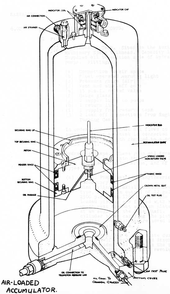
(4) Air Loaded Accumulators.
Two fitted, (one in ACS, one in AMS) to avoid running the pumps continuously and to maintain pressure when the pumps are stopped. Each accumulator has two air bottles to provide the volume of air necessary for the correct operating pressure range of the accumulator.
(5) Hydraulic Return Lines. To collect oil after it has been used in the hydraulically operated fittings and return it to the replenishing tank.
6-7
Automatic Control System
(Figure 3)
6-8
6.02 MAIN HYDRAULIC SYSTEM (CONTD.)
A2 Fittings
(6) Distribution Valve Chests. To enable each hydraulically operated fitting to be connected to the pressure and return lines via individual valves.
(7) Filters. Filters are fitted in various positions in order to keep the oil clean.
(8) Pump Relief Valves. These valves set at 2600 p.s.i. are fitted between the pump discharge and the return line to relieve the system if an excessive pressure builds
up.
(9) Main Bye-Pass Valve. Fitted across the pressure and return lines in the control room. Provides a quick means of collapsing the pressure in an emergency.
(10) Hydraulic Storage Tank. Capacity 240 gal. Situated under A.M.S. to carry oil for topping up the hydraulic system. Oil can be transferred to the replenishing tank by a semi-rotary hand pump.
B1 The Automatic Control System
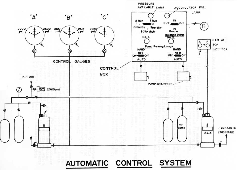
Fitted to maintain an oil pressure in the system between certain set limits automatically. This is achieved by using special control gauges and electrical relay circuits, which automatically stop and start the pumps as required.
(1) Control Gauges. Fitted in the control room. Each gauge has a main pointer which indicates the pressure of oil in the system. There are two other pointers, the upper and lower limit setting pointers, which are set and fixed at the pressure limits. When the main pointer touches the contact on either of the setting pointers a 24 volt circuit is energised, which, through the control box either stops or starts the pumps, or operates the indicator lights and buzzer, as follows:
6-9
6.02 MAIN HYDRAULIC SYSTEM (CONTD)
B1 The Automatic Control System (cont'd.)
(1) cont'd.
Gauge A. Operates the indicator lights and buzzer, the setting pointers are set at 2000 p.s.i. and 2500 p.s.i.
Gauge B. Controls the starter relay of the running pump, the setting pointer is set at 2100 p.s.i. and 2515 p.s.i.
Gauge C. Controls the starter relay of the stand-by pump, the setting pointer is set at 2050 p.s.i.
(2) Control Box. Fitted in the control room, has the control switches, lights, buzzers and pump starter relays. Fittings are:
Pressure Available Lamp. Burns continuously while pressure is above 2000 p.s.i. If pressure falls below 2000 p.s.i. the lamp will flash and the buzzer will sound. Controlled by gauge A.
Accumulator Full Lamp. Will burn continuously while pressure in system is above 2500 p.s.i. Controlled by Gauge A.
Pump Binning Lamps. One for each pump to indicate that it is running.
Pump Selector Switches. Selects whichever combination of running and stand-by pump is required.
Pump Control Switches. One for each pump with three positions: auto- hand- off; in auto-, pumps are controlled by gauges B and C; in hand-, pumps will start when switches are made to the hand position.
Buzzer Isolating Switch. To isolate buzzer in quiet states.
6-10
6.02 MAIN HYDRAULIC SYSTEM (CONTD)
B1 The Automatic Control System (contd)
(2) Control Box (contd)
Note Failures: If the control box ceases to function the pumps can be started by the hand switches on the starting box. If the whole system fails then pressure can be produced using three high pressure hand pumps, one in the F.T.R., one in the engine room and the other in the A.T.R. Each pump has its own 3-gal. replenishing tank and associated stop valves.
C. Hydraulic Valves
1. Control Valves
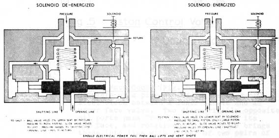
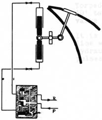
(a) Hydel. (Fig. 4) A solenoid operated ball valve controls the supply of hydraulic oil to the equipment, through a slide valve which gives a positive flow of oil in either of two directions.
Fig. 4
6-11
6.02 MAIN HYDRAULIC SYSTEM (CONTD)
C. Hydraulic Valves
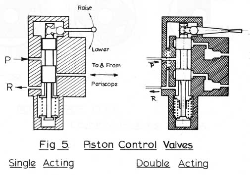
(b) Piston. Single and Double Acting (Fig. 5) Dumbell shaped sliding in a bore, opening and closing ports drilled into the bore, these being led to either side of the equipment to be operated. Centralises itself by spring action. Used where sensitive control is needed, i.e. periscopes, hydroplanes and steering.
Fig 5
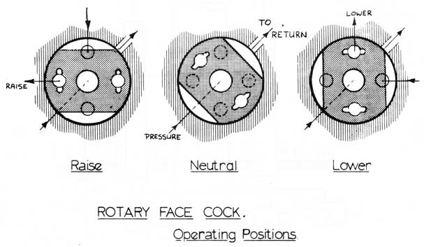
(c) Rotary Face Cock. (Fig. 6)
Consists of a plug housed in the bore of a steel block between a lower sleeve and an upper face valve. Two diametrically opposite oil ports pass from its underside to its top face, and rotation of the handle brings these into line with either of two pairs of diametrically opposite ports in the upper face valve. Each of these pairs of ports is led to one side or the other of the equipment to be operated. Flats cut on the side of the control valve ensure that the return port is always in connection with one pair of ports.
6-12
6.02 MAIN HYDRAULIC SYSTEM (CONTD)
C. Rotary Face Cock (contd)
Fig 6
D. Equipment
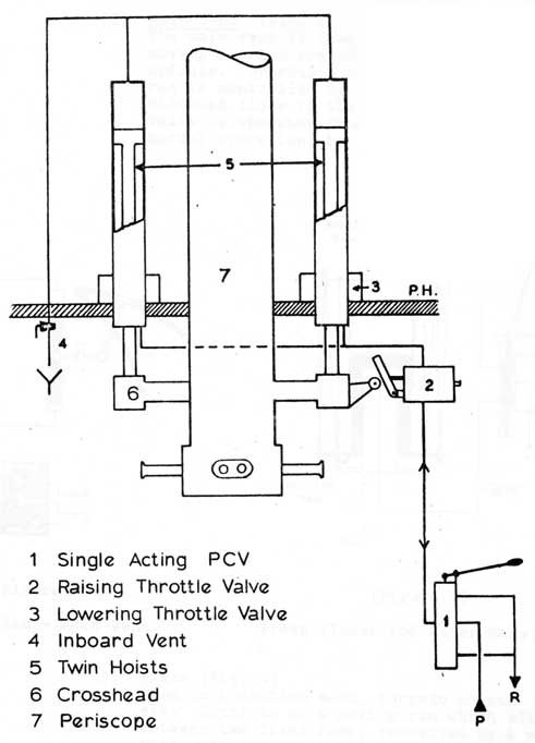
(1) Twin Piston Hoist (Fig. 7)
Two hoists fitted to the crossheads of periscopes, Radar Mast, Communication Mast and E.C.M. masts. These extend through the hull, into external cylinders. Incorporate Raising and Lowering throttle valves.
6-13
6.02 MAIN HYDRAULIC SYSTEM (CONTD)
D. Equipment (contd)
Fig 7 HYDRAULIC TWIN HOIST
6-14
6.02 MAIN HYDRAULIC SYSTEM (CONTD)
D. Equipment (contd)
(2) Main Vent (Fig. 8)
The main vent is opened by a double ram moving a crank arm connected to the vent spindle. Hydraulic pressure to the double ram is controlled by a 'hydel valve, situated close to the vent. The hydel valve is operated from the control room in normal operation, but can be worked locally.
(Figure 8)
Double Ram - Main Vent
(Figure 9)
Press (Inner and Outer Rams)
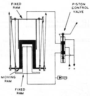
(3) Press (Fig. 9)
Used on induction mast, torpedo hoists etc. Consists of a moving ram which slides between two fixed rams, connected by a wire rope, working over pulley wheels, to the equipment. Controlled by a double acting piston control valve.
6-15
6.02 MAIN HYDRAULIC SYSTEM (CONTD)
D. Equipment (contd)
(4) Hydraulic Motors. Hydraulic Pressure operates rams which push against eccentrics mounted on the drive shaft, so turning shaft.
Capstan and Windlass have 3 eccentrics and 6 rams
Snorkel Exhaust Motor has 1 eccentric and 3 rams
Torpedo Ramming Motor has 1 eccentric and 5 rams
Turning Gear (Deri Sine) has 2 eccentrics, direct oil pressure.
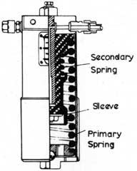
(5) A combined spring-loaded accumulator and shock absorber, (Fig. 10) is fitted on the shutting line of each of the following important fittings:
Torpedo Muzzle Doors (8), 'Q' tank kingston (1), 'D' tank kingstons (2), and the snorkel induction valve (1).
It is fitted to maintain pressure in the shutting line when the fitting is isolated from the hydraulic system and to absorb pressure impulses due to shock, i.e. depth charging.
SPRING- LOADED ACCUMULATOR
(Figure 10)
HYDRAULIC HAND PUMP
(Figure 11)
6-16
6.02 MAIN HYDRAULIC SYSTEM (CONTD)
D. Equipment (contd)
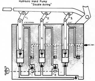
(6) Hydraulic Hand Pumps (Fig. 11)
One large piston (a) and two small pistons (b & c) worked by a hand lever, all with double acting action. The four powers are obtained by using the three pistons in different combinations. Fitted in forward and after torpedo rooms and Engine Room.
Position 1 - all pistons working - (340 lb/sq.in.)
Position 2 - pistons a. and c. - (450 lb/sq.in.)
Position 3 - pistons b. and c. - (830 lb/sq.in.)
Position 4 - piston c - (2,100 lb/sq.in.)
6-17
Large Plate on Separate Page
Arrangement of Capstan and Anchor Gear in Casing Fig 11
6-18
C. F. 'O' CLASS SUBMARINES
CAPSTAN, WINDLASS, ANCHOR AND CABLE EQUIPMENT
6.03 INTRODUCTION
A. Design data
The capstan and windlass gears are designed to meet the following requirements:
Capstan. To exert pulls in either direction of rotation of:
3 tons at 30 ft./min.
1 7/8 tons at 48 ft./min.
3/4 ton at 120 ft./min.
Windlass.
(a) To lift in the cable holder:
6 tons at 15 ft./min.
3 3/4 tons at 24 ft./min.
1 1/2 tons at 40 ft./min.
1 ton at 60 ft./min.
(b) To veer the cable at a maximum speed of 60 ft./min. with a load on the cable not exceeding 1 tons.
(c) To withstand a pull of 13 tons on the cable.
(d) The brake gear to be capable of holding a load of 6 tons with the clutch disengaged.
(e) The gear to be self holding.
B. General Arrangement (Fig. 11)
The arrangement of capstan and windlass gears in the casing is shown in Fig. 1 from which it will be seen that they are completely separate, each having its own hydraulic motor enclosed in a watertight box. Main and selector control valves housed in a single block, sited within the pressure hull, but operable from the casing regulate each
motor.
6-19
6.03 INTRODUCTION (CONTD)
B. General Arrangement (contd)
The main control valve governs the direction and speed of rotation of its motor, and the
selector control valve the power required of the motor, viz., full, intermediate or light. Each control valve block houses a third valve which limits the oil consumption of its motor to 3,100 cu.in./min.
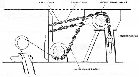
One anchor and 75 fathoms of cable are provided. The anchor is housed in a recess in the port side of the bow, the recess being closed by a hinged fairing plate operated by screw gear from the superstructure deck. The cable is secured to the bottom of the cable locker by a clench tested to 20 tons.
Blake and screw stoppers (Fig. 12) and a cable compressor are also fitted.
Fig 12
Blake and Screw Stoppers
6-20
6.04 CAPSTAN GEAR (Figs. 3, 4, 5)
Power, to the warping barrel is transmitted from its hydraulic motor through an Oldham type coupling in the watertight box, to a manganese bronze wormshaft, whose worm drives a wormwheel keyed to a vertical shaft, the top end of which is squared to carry the warping barrel, which is held by a retaining plate and central bolt.
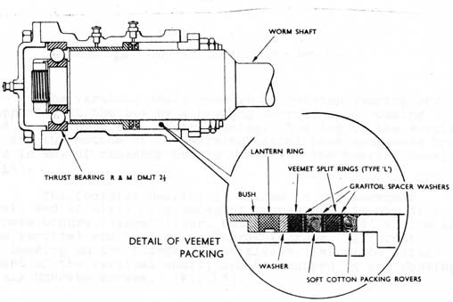
The wormshaft is supported in two split end bearings, one adjacent to the motor together with a stuffing box is carried in a housing bolted to the forward wall of the watertight box, and the other which includes a thrust bearing (R. & M. DMJT 2 1/2 in.) with protective stuffing box (Fig. 13) is housed in the wormgear bracket casting.
Fig. 13 Capstan and Windlass - Drive Shaft forward bearing
6-21
6.04 CAPSTAN GEAR (CONTD)
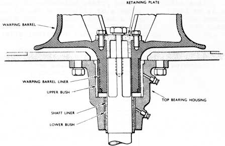
Fig. 14 Capstan Spindle - Top Bearing
The vertical shaft runs in a footstep bearing and is supported at the top by a bearing carried in a housing
bolted to the underside of the casing. The top of the vertical shaft and the bottom of the warping barrel have manganese bronze liners in way of phosphor bronze bushes in the bearing housing
(Fig. 14).
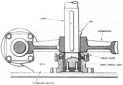
The footstep bearing is housed in the wormgear bracket, and consists of a phosphor bronze bush in way of a manganese bronze flanged liner, which is secured at the bottom of the vertical shaft with two Unbrako screws. A thrust plate bearing on the flange of the sleeve limits the axial movement of the vertical shaft, and is secured to the housing with six Unbrako screws. (Fig. 15).
6-22
6.05 WINDLASS GEAR
Power to the cable holder is transmitted from its hydraulic motor through an Oldham type coupling in the watertight box, an extension shaft, an intermediate shaft, and a phosphor bronze wormshaft, to a wormwheel keyed to an athwartships main shaft, which carried a clutch, and the combined cable holder and brake drum. The clutch and brake controls, and a cable indicator ring are mounted on the casing.
The drive shaft assembly is supported in three split bearings. One adjacent to the motor and the foremost one are similar to those described for the capstan wormshaft, and the centre one is housed in the bedplate.
Fig. 15 Capstan Spindle - Footstep Bearing
The main shaft is also supported in three split bearings housed in bed plate pedestals, and between the free end and centre bearing, the clutch and the combined cable holder and brake drum is carried.
6-23
6.05 WINDLASS GEAR (CONTD)
The cable holder is bushed in phosphor bronze and the main shaft is sleeved in manganese bronze in way of this and the three bearings. The combined cable holder and brake drum is free to revolve on the main shaft, and is clutched to it for controlled veering or hauling of the cable.
The dog type clutch slides over keys in a manganese bronze liner, which is keyed to the main shaft, and its movement is controlled by its operating rod engaging with a split floating ring in a groove around the clutch.
A steel Ferodo lined brake band, comprising hinged top and bottom halves, enclosed the brake drum. The open end of the top half is fixed, and the brake control functions through a spindle screwing into a nut in the eye of the lower half.
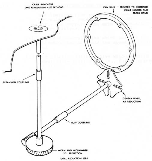
A cam ring carrying a pin is attached to the side flange of the brake drum. The pin engages with Geneva wheel keyed to a spindle, which drives through wormgear the cable indicator. The Geneva wheel and wormgear give reductions of 4 to 1 and 57 to 1 respectively. This total reduction of 228 to 1 of the cable indicator drive gives one revolution for 100 fathoms (Fig.16).
All points requiring lubrication are fitted with Tecalemit nipples. The nipples are readily accessible with the exception of five on each Oldham coupling and one on each hydraulic motor gland. Access to these is by a handhole door bolted to the cover of each watertight box.
6.06 HYDRAULIC MOTORS
The MacTaggart Scott, type 3 1/2 in. centres, hydraulic motor has three pairs of cylinders horizontally opposed, with plungers operated by hydraulic pressure piped through the pressure hull driving a shaft through eccentrics. The motors for both capstan and windlass are identical in construction and operation.
6-24
Fig. 16 Cable Indicator Drive
6.07 CONTROL AND LIMITING FLOW VALVES
The main control and selector control valves sited in the F.T.R. are operated from the casing and are connected by rod gearing, expansion and universal couplings, via hull glands, to pinions engaging sectors pinned to the valve operating rods. The valves are housed together with a limiting flow valve in a steel block sited within the pressure hull. The three valves are individual and control:
6-25
6.07 CONTROL AND LIMITING FLOW VALVES (CONTD)
(a) the limiting flow valve which restricts hydraulic oil consumption to 3,100 cu. in/ min., and supplies the main and selector control valves.
(b) the main control valve which selects the direction and controls the speed of rotation, and
(c) the selector control valve which selects the power to be developed, i.e., full, intermediate or light.
6-26
Large Plate on Separate Page
STEERING SYSTEM
Starboard Steering Cylinder Shown Shut-off and By-passed Page 6-26
6-27
6.08 STEERING SYSTEM
A. General
The rudder of the submarine is moved by
hydraulic power. The main steering position is in the Control Room using One Man Control equipment (OMC).
Emergency methods of control are provided in the ATR.
An automatic pilot can be clutched in, enabling the boat to be steered on a pre-determined course, or an evasive zig-zag about a mean course. Automatic circling for 186 searches is also incorporated.
B. Description
The steering equipment consists of a rudder, fitted with a crosshead which is connected by shafting to two hydraulic cylinders.
Oil under pressure is admitted to these cylinders
through a piston control valve (called a distributor
valve) which is operated by the helmsman using the
OMC gear. The distributor valve is part of a ram
servo unit, which also houses the receiver of the
OMC gear, this being coupled to the distributor
valve by levers. When the steering wheel is turned
by the helmsman this order is transmitted by the
OMC equipment to the receiver, which in turn moves
the distributor valve; so allowing hydraulic
pressure to the cylinders. As the steering cylinders
approach the required new position, a lever, connected
to one of the cylinders and to the distributor
valve, moves the distributor valve back to its
neutral position thus stopping the movement.
A changeover valve is fitted between the distributor valve and the steering cylinders. This is held in the primary position by hydraulic pressure, but should hydraulic pressure fail, a spring will move the changeover valve to a local control position, and oil can be admitted to the cylinders using a piston control valve fitted in the ATR, this oil pressure coming from the distribution valve chest in the ATR (local control) or from a hand pump (emergency control).
6-28
Large Plate on Separate Page
Stern Planes & OMC Page 6-28
6-29
6.08 STEERING SYSTEM (CONTD)
B. Description (contd)
Hydraulic failure can be simulated, or the changeover valve moved to the local control position by operating a selector valve, this allows the hydraulic pressure which was holding the changeover valve in the primary position, to bypass to return, so allowing the spring to move the changeover valve to the local control position.
One cylinder can be isolated and its oil allowed to bypass by using a Relief and Distribution Valve fitted between the distributor valve and the cylinders, so effecting an economy of hydraulic pressure in good weather. This valve incorporates relief valves to protect against excessive pressures caused by shock of heavy seas.
6.09 HYDROPLANES
A. General
Hydroplanes are fitted at the bow and at the stern so that the angle and the depth of the submarine can be controlled. They are in effect, horizontal rudders and like the rudder they are connected to a hydraulic cylinder by shafts.
They are controlled in the same manner as the rudder and also have similar methods of emergency control. The exception being the stern planes which have an air cylinder mounted on the shaft and this is the first emergency method for these planes.
To protect the bow planes when entering or leaving harbour, another hydraulic cylinder is fitted so they can be "housed" or folded up alongside the casing and "lowered" after leaving harbour.
B. Description - Stern Planes
The Stern Planes are mounted on a shaft one on either side of the rudder post in line with the wake of the propellors.
6-30
BOW PLANE OPERATING GEAR
6-31
6.09 HYDROPLANES (CONTD)
B. Description - Stern Planes (contd)
They are connected by shafts, a bell crank lever and a crosshead, through the pressure hull to the oil and air cylinders. Hydraulic pressure is admitted to the oil cylinder through a distributor valve in the same manner as the steering gear and this distributor valve also is moved by operating the joystick in the control room. Local control and hand pump emergency are obtainable like the steering gear.
As the stern planes have more effect on the control of the submarine than the bow planes, they are fitted with a method of air control which can be brought into operation by the helmsman depressing a trigger switch on the air control valve handle. This changes over an air/oil by-pass valve which shuts the air by-pass valve and allows the oil cylinder to by-pass. Movement of the air control valve handle allows air to enter the air cylinder through the air/oil by-pass valve. This air is supplied from the HP air ring main through an automatic reducing valve at 1500 PSI. This air supply is always open at sea and thus stern planes may be moved to Air Control in an emergency in less than a second.
Also like the steering gear, the automatic pilot can be clutched in to maintain depth and angle.
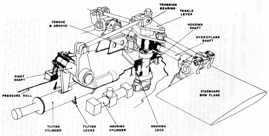
C. Bow Planes
The Bow Planes are also mounted on a shaft running athwartships over the top of the pressure hull. The planes are hinged to this shaft. They are also connected to a toggle lever, which is turned by a housing shaft connected to an oil cylinder inside the submarine. Operation of this cylinder will cause the toggle to turn, thus pulling in or lowering the planes
A second oil cylinder inside the submarine is connected through a pivot shaft to a trunnion bearing on the toggle lever, and operation of this cylinder causes the whole hydroplane assembly to tilt, this made possible by manufacturing the housing shaft in two pieces, machining a groove in the lower piece and forming a tongue in the top piece, the tongue sliding in the groove.
6-32
Bow Planes
6-33
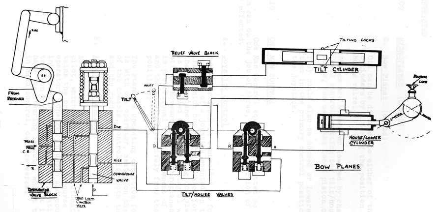
6.09 HYDROPLANES (CONTD)
C. Bow Planes (contd)
Oil can be directed to either of the two oil cylinders by altering the position of a tilt/ house valve.
Planes are housed or lowered by changing into local control, putting the tilt/house valve to house, and using the local piston control valve.
They could also be housed or lowered by leaving them in the primary control position and using the joystick.
6.10 ONE MAN CONTROL
One Man Control equipment is fitted so that one man can do the job of three, thus a reduction of man power is effected.
A. Joystick Control
Submarine depth is controlled by fore and aft movement of a joystick mounted on the order transmission box (0.T.B.) which forms part of the hydroplane and steering console; steering is controlled by a wheel integral with the joystick. Movement of the hydroplanes and rudder is proportional to the movement of the joystick and the wheel respectively from their central positions.
The standard operating condition for the gear is with one operator, seated on the port side of the console, controlling both the hydroplanes and the rudder.
B. Automatic Control
Attached to the front of the O.T.B. is the autopilot, which on engagement, automatically maintains the ordered depth and course as set by the operator. Changes in depth and course can be introduced during automatic operation using controls on the automatic pilot. It is possible to have the steering in auto, whilst the depth is in hand control, or vice versa.
6-34
6.10 ONE MAN CONTROL (CONTD)
B. Automatic Control (contd)
The auto pilot incorporates programmed steering, and alternative programmes can be steered to master patterns using different Cams.
In the event of failure of the primary method of Control of either the hydroplanes or steering, only that one equipment need be operated in
local control.
6-35
C. F. 'O' CLASS SUBMARINES
6.10 ONE MAN CONTROL (Figure 1)
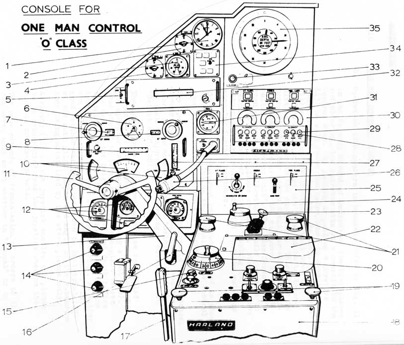
A. Console Fittings
1. Clock
2. Switch for bridge, compass repeater
3. Heel Indicator
4. Switch for bridge rudder repeater
5. Gyro repeater switch
6. Shallow water depth gauge (30 - 70 ft)
7. Course indicator - the ordered course is set manually by turning the knob and the course set is indicated in a window.
8. Depth indicator - Note: If on auto pilot, the course and depth setting dials above must be kept up to date with the course and depth setting dials of the auto pilot so that an immediate change from auto to manual can be effected.
9. Course error instrument dial
10. Repeat dials to indicate actual position of planes and rudder (similar repeats are fitted on the O.O.W. Console)
11. Steering Wheel
12. Motor tachometers, telegraph repeats and grouper lights.
13. Joystick
14. Dimmer Switches
15. High, low speed setting of automatic pilot.
6-36
6.10 ONE MAN CONTROL (CONTD)
A. Console Fittings (contd)
16. Clutch to enable steering only to be carried out using the joystick.
17. Stern plane emergency air control lever.
18. Automatic pilot
19. Auto pilot engagement knobs (pull up)
20. Depth control
21. Balance plane angle control for bow and stern planes.
22. Perspex cover over course setting knob.
23. Clutch to engage or disengage bow planes. When disengaged, stern planes only will move in response to auto-pilot or joystick.
24. Stern plane percentage control.
25. Hydraulic transmission service unit - to enable accumulators on the hydraulic transmission system to be pumped up.
26. Action/main intercom
27. Depth error instrument dial;
28. Select 'HYD' push button
29. Select 'ELE' push button
30. Monitor panel for rudder, bow and stern planes. Holds the mode selection buttons, mode indicators, control operative lamps and misalignment indicators.
31. Trim indicator
32. Gyro repeater
33. 'Klaxon' alarm push button
34. Gyro torpedo battery alarm
35. Combined shallow and deep depth gauge.
6-37
Figure 1
6-38
6.10 ONE MAN CONTROL (CONTD)
B. Operation (The numbers in brackets refer to Fig. 1)
In the Primary Method of Control of the hydroplanes and steering, the operator sits at a console in the Control Room. By pushing or pulling a joystick (13) he will cause the hydroplanes to move so he can control depth and angle. By turning the wheel (11) mounted on the joystick he will move the rudder. When he moves the joystick he is transmitting an order to the equipment. This order is transmitted either hydraulically or electrically. The order is received at the equipment by a unit called a "Ham Servo Unit". The "Ram Servo Unit" then opens a valve allowing hydraulic pressure to operate the hydroplanes or rudder. When they have reached the desired position a "hunting lever", attached to the equipment, will shut the valve so stopping further movement.
The amount the equipment has actually moved is shown on repeat dials (10) on the console in the control room so correct operation can be checked.
The operator can change from hydraulic to electrical transmission by pushing a button on the monitor panel of the console, called "Select ELE" (29) or back to hydraulic by pushing a button called "Select HYD" (28).
The hydroplanes and steering can be controlled automatically by using an auto pilot (18) which the operator can engage by lifting a knob (29). Case should be taken that the auto-pilot is set the same as the original course and depth before engaging. One engaging knob is provided for the hydroplanes and another for the steering, so either can be in auto, irrespective of the other. In good weather the bow planes can be declutched (23) at the auto pilot, depth and angle of the submarine then being maintained by the stern planes only.
A clutch (16) on the joystick enables the planes to be deconnected from the joystick when on the surface or when in auto.
The same methods of transmission of orders to the ram servo unit exist whether in "manual" or in
"auto" (i.e. hydraulic or electrical).
6-39
6.10 ONE MAN CONTROL (CONTD)
B. Operation (contd)
When operating manually, the operator can steer
the correct course by observing the gyro repeater tape (32) in front of him, or, more simply by keeping his course error dial (9) in its zero position. Similarly, when controlling depth he can work either to his depth gauges (6)(35)
or by keeping his depth error instrument (27)
on zero, the correct depth and course having
been previously set on the set depth/set course
units (7)(8).
When operating in "auto pilot" the ordered depth and course are obtained by setting the controls on the "auto pilot", the depth control (20) is graduated from 0-1000 ft. in 1 ft. divisions, the course control (22) is graduated 0-360°. Cams may be fitted which enable pre-determined zigzags to be steered, or a gear wheel, for steady turning in a circle for 186 searches.
C. Alternative Methods of Control
In the event of any emergencies, the steering or planes are immediately changed to "Emergency" control. On receiving the order, the watchkeeper in the FTR or ATR changes over to "local" control and mans a hand pump to obtain pressure, this pressure being controlled by a piston control valve.
The watchkeeper can then either maintain an ordered course or depth, or follow an indicator which shows an order transmitted by the C.R. operator. If hydraulic pressure fails the equipment will automatically change to "emergency".
Another method of control is called "local control". This is identical to "emergency" except that the hand pump is not manned, hydraulic pressure being obtained from the distribution valve chests adjacent to the equipment, the same piston control valve being used for control.
The stern planes, being fitted in the wake of the propellors, have more effect on the angle and depth control of the submarine than the bow planes and as the submarine can be controlled by stern planes only it is considered essential to get these back in operation as quickly as possible should there be a hydraulic failure. The stern
6-40
6.10 ONE MAN CONTROL (CONTD)
C. Alternative Methods of Control (contd)
planes therefore have another method of control called "air emergency" and the operator brings this into operation by depressing the trigger on a control valve lever (7) fitted beside his seat, movement of this lever fore/aft will cause the stern planes to move to dive or rise under air pressure.
6.11 LIST OF HYDRAULICALLY OPERATED FITTINGS
Q & M.B.T. Vents
Torpedo Ramming Gear Raise/Lower Crosshead
Q & D Tank Kingstons
Torpedo Lifting Hoist
Bow Plane Housing
Torpedo Traversing Gear
Bow Plane Tilting
Torpedo H.E. Sluice Valves
Stern Plane Tilting
Capstan and Windlass
Steering
Induction Hull Valve
Snorkel Induction Mast
Auto Pilot
Snorkel Exhaust Mast
Engine Turning Gear
Alk Doors & Winch & Cutter
Can Crusher
Periscopes, Radar, E.C.M., W.T. Masts
Snorkel Muffler Valve
Torpedo Muzzle Doors
Engine inlet valves After services inlet valves Air compressor inlet valve Supply to refrigerating MCY