C.F. 'O' Class Submarines - Diesel Engines, describes the engines and associated equipment of the Oberon class submarines.
In this online version of the manual we have attempted to keep the flavor of the original layout while taking advantage of the Web's universal accessibility. Different browsers and fonts will cause the text to move, but the text will remain roughly where it is in the original manual. In addition to errors we have attempted to preserve from the original, this text was captured by a combination of optical character recognition and human typist. Each method creates errors that are compounded while encoding for the Web. Please report any typos, or particularly annoying layout issues with the Mail Feedback Form for correction.
Combustion, The diesel engine is a compression ignition engine, and relies upon a high compression ratio to achieve ignition temperature within the cylinder. The combustion of fuel within the cylinders occurs in three distinct stages.
(1) The Delay Period
The delay period is the time taken for the fuel injected to attain spontaneous ignition temperature. It depends upon:
(a) Compression Ratio (i.e. Air Temperature in cylinders).
(b) Nature of fuel
(c) Degree of atomisation of fuel
(d) Degree of mixing of fuel particles and air.
(2) Uncontrolled Combustion
Occurs when the fuel (which has been continuously injected during the delay period) achieves spontaneous ignition temperature and ignites. It depends upon:
(a) Length of delay period
(b) Rate of fuel injection.
The cylinder pressures and temperatures attained during the uncontrolled phase of combustion depend upon the position, and the speed of the piston when the ignition occurs.
13-2
(3) Controlled Combustion
Occurs after the uncontrolled phase and represents the steady combustion of fuel injected after ignition and uncontrolled combustion. It depends upon:
(a) Rate of fuel injection
(b) Amount of usable air left after the uncontrolled phase
(c) Time of fuel cut-off.
In order to control the shape of the P.V. diagram of the cycle, the minimum amount of uncontrolled combustion is required. Thus the delay period must be reduced to a minimum. This can be achieved by atomisation of the fuel on injection, by imparting turbulence to the air/fuel mixture in the cylinder, or by using high compression ratios, hot spots etc.
Having minimised the delay period and hence the amount of uncontrolled combustion, the shape of the P.V. diagram (and hence the work output of the cycle) can be adjusted by altering the point of commencement of
injection.
It will be realised from the above that the following factors are of prime importance if the efficiency of a diesel engine is to be maintained.
(1) Compression Ratio. Proper care of valves and piston rings.
(2) Injection of Fuel. Correct timing, and good maintenance of injectors and pumps.
(3) Turbulence. Cleanliness of valve ports and cylinders (carbon deposits etc).
(4) Power/Weight Ratio. In order to increase the power/weight ratio of a given size of engine, methods must be found to increase the amount of fuel/stroke which can be burnt within the cylinder.
13-3
The amount of fuel burnt depends entirely upon the amount of oxygen available for each firing stroke. Three methods are available:
(1) Scavaging
After each exhaust stroke there is a small amount of exhaust gas left in the cylinder during the subsequent induction stroke. This reduces the amount of fresh air induced, and consequently the amount of oxygen is less. By arranging for a small period of valve overlap (i.e. exhaust and inlet valves open at the same time) during the induction stroke, the incoming fresh air can be used to blow the exhaust gas out. This is known as 'Scavenging'.
(2) Supercharging
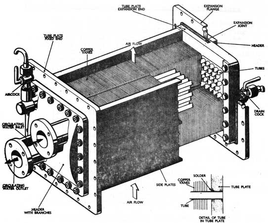
By increasing the density of the air supply more oxygen molecules are made available for combustion per unit volume of the engine. To increase the density it is necessary to increase the pressure without excessive increase in temperature of the air, consequently, supercharger air coolers are invariably used.
NOTE: In a supercharged engine it is possible to reduce the amount of valve overlap, as the scavenging will be more effective.
(3) High Rotational Speed
ay running the engine at high speeds, more working strokes/min. are available, and consequently a smaller engine can be made to give a higher power output. The ultimate limit on rev/min. however is controlled by the length of the delay period which in modern engines is roughly constant at 0.0015 - 0.0027 seconds.
13-4
Thus the modern diesel engine is designed with the following factors in mind.
(a) Minimum delay period
(b) Supercharging
(c) Scavenging
(d) High speed
In increasing the power/weight ratio and rotational speed of the engine, the design of components becomes very critical, and fits, tolerances, finish and lubrication are of prime importance if the engine is to be mechanically reliable. The A.S.R.I. engine has been designed on these principles and represent a considerable advance on previous submarine diesels.
Power Considerations. The power developed by a diesel engine can be written as:
Power = P x V x S
P = Mean pressure in cylinder
V = Volume swept by piston
S = Working strokes/unit time
For a constant speed engine, the only variable is F. This will vary directly with the amount of fuel injected. Since excess air is supplied to ensure complete combustion of fuel, it is possible to overload a diesel by supplying excess fuel. The effects of overload are:
(1) To increase the maximum cylinder pressure and temperature beyond the design limits with eventual failure by overheating or seizure.
(2) To increase the thrust on the crankshaft large end bearings and to increase the torsional vibrations of the crankshaft, beyond design limits.
Thus for a constant speed engine the maximum load permissible can be expressed as a rate of fuel consumption (i.e. as a maximum value of P)
i.e. lb/hour fuel
13-5
For a variable speed engine however, the power formula can be written:
Power = P.V.S.
therefore P = Power/V.S.
It will be seen that in this case there are two
Variables:
(a) Mean Pressure - varying directly with fuel.
(b) S - varying with rev/min. Further, P varies inversely with S.
Thus assuming an engine is working at a fixed power output, at a given speed the value of P may be within design limits. If however S should decrease, P will become excessive.
Thus the load factor for the engine must be written as:
P/S proportional to (lb/hour) / (rev/min.)
to account for this possibility.
In practice then to check the state of load of a running engine, we can measure the fuel consumption and the speed and calculate the loading. Fuel consumption is
measured by timing the usage of a fixed and known quantity of fuel from a snap tank. The reading is then used to work out the lb/hour.
The conversion factors are combined into a Snap Tank Constant:
Snap Tank Constant = Specific Gravity x capacity (gal) x 10 x 3600
By dividing the snap tank constant by the time taken to use the tank (in secs) we obtain the lb/hour of fuel consumed.
The load factor for the engine then is
Snap Tank Constant / (Time in Secs. x Engine rev/min.)
13-6
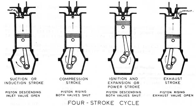
Four-Stroke Cycle
13-7
Effects of Snorkelling on a Diesel Engine
Induction.
Because of the pressure drop in the snorkel induction system, the air pressure at inlet to the engine or supercharger will be below atmospheric. Since the pressure drop increases as the air flow increases, then the suction depression will increase as power increases. The effect of suction depression is caused by the reduction of air density available for combustion. Thus, to get a fixed power output from the engine, more fuel must be injected, and consequently the specific fuel consumption, and the exhaust temperature will increase with suction depression.
Exhaust.
As with the induction system, the pressure drop in the snorkel exhaust system will increase with engine power. As the pressure at the exhaust mast outlet depends upon the depth, then the back pressure on the engine will vary with:
(a) Engine Power
(b) Depth
As the back pressure increases, the useful expansion of the combustion gasses is reduced, and consequently power output is reduced, and exhaust temperature increases.
The A.S.R.I. 16 V.M.S. Engine, fitted in C.F. 'O'
class submarines is a 16 cylinder 4 stroke V engine, mechanically supercharged.
Specification
No. of cylinders
16.
Cycle
4-stroke.
stroke
10.5 in.
Bore
9.75 in.
Compression Ratio
12.7 : 1.
Rev/min.
750-920.
Maximum B.H.P. (Supercharged)
1840 (surface).
Maximum B.H.P. (Unsupercharged)
1180 (surface)
Brake M.E.P. (Normal aspiration)
80 lb/sq. in.
Brake M.E.P. (Supercharged)
126.3 lb/sq. in.
Max. Cylinder Pressure (Normal aspiration)
860-940 lb/sq. in.
Max. Cylinder Pressure (Supercharged)
1,280 lb/sq. in.
Compression Pressure (hot) (Normal aspiration)
480 lb/sq. in.
Dimensions and Weights
The following particulars are approximate only, for purposes of lifting and transport:
Length (including 6 in. void)
18 ft. 7 in.
Breadth
10 ft. 0 in.
Height
5 ft. 10 in.
Weight (including 6 in. void)
21 tons.
13-8
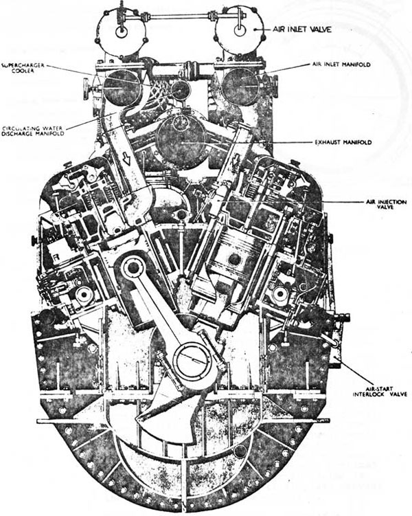
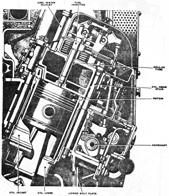
Sectional View 16 V.M.S. Engine
13-9
Direction of Rotation
Clockwise looking on FREE end of engine.
Identification of Cylinders
The cylinders are numbered from the FREE end of the engine; the banks of cylinders are defined as LEFT and RIGHT looking on the DRIVE end of the engine.
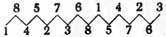
Cylinder Firing Order
Left bank
Right bank
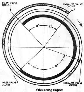
Timing, Inlet and Exhaust Valves
Inlet valve opens
32° before T.D.C.
Inlet valve closes
46° after B.D.C.
Exhaust valve opens
56° before B.D.C.
Exhaust valve closes
22° after T.D.C.
Valve overlap
54°.
All data are to crank-angle basis.
Timing, Fuel Injection
(Timing gear retarded one degree on crank-angle basis.)
26.5-27° before T.D.C. (See Mod. No. 85.)
Valve timing diagram
13.02 CONSTRUCTION
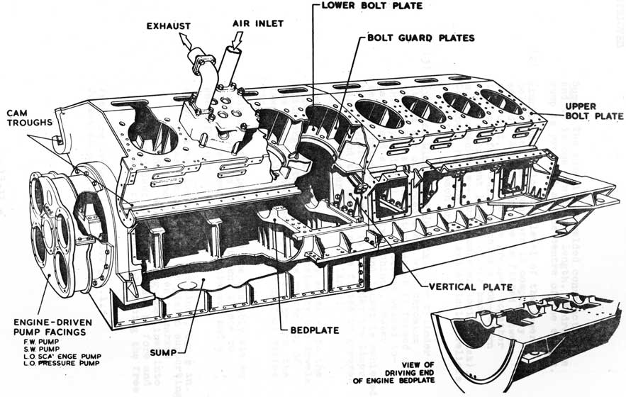
(1) Engine Frames. The engine framing consists of three main sub-components:
Cylinder Frames
Bedplate
Sump
The components are of fabricated steel welded construction, and are joined together to form the engine framing by fitted bolts.
Cylinder Frames. Made in two sections of 8 cylinders each. The upper bolt plate forms the top support plate for the cylinder assembly. The cylinder head bolts pass through the bolt plate. The lower bolt plate is extended to form the cam troughs and fuel pump supports, tapped holes being provided to receive the lower threaded portion of the cylinder head bolts. Vertical joint plates are fitted between each pair of cylinders and at each end of the engine. On the free-end vertical plate, the damper and pump drive casing is bolted. The drive and vertical plate carries the platform for the superchargers.
Bedplate. The bedplates consists of a horizontal plate with slots provided in way of the crank throws, and a wrapper plate which has oil drain holes out in it in way of each throw. Transverse plates are fitted between each unit to contain the crankshaft main bearing beds.
13-10
ENGINE FRAMES
13-11
Sump. The sump is of welded construction
and is in one continuous length. A drainage sump is provided at the centre of the engine.
(2) Crankcase. Below the level of the lower bolt plate, the crankcase is completely sealed. A breather pipe is fitted between each unit, and these are grouped together in a manifold which contains a non-return valve to prevent leakage of air back into a hot crankcase - (crankcase explosion risk). Crankcase handhole doors and explosion reliefs are fitted to each unit.
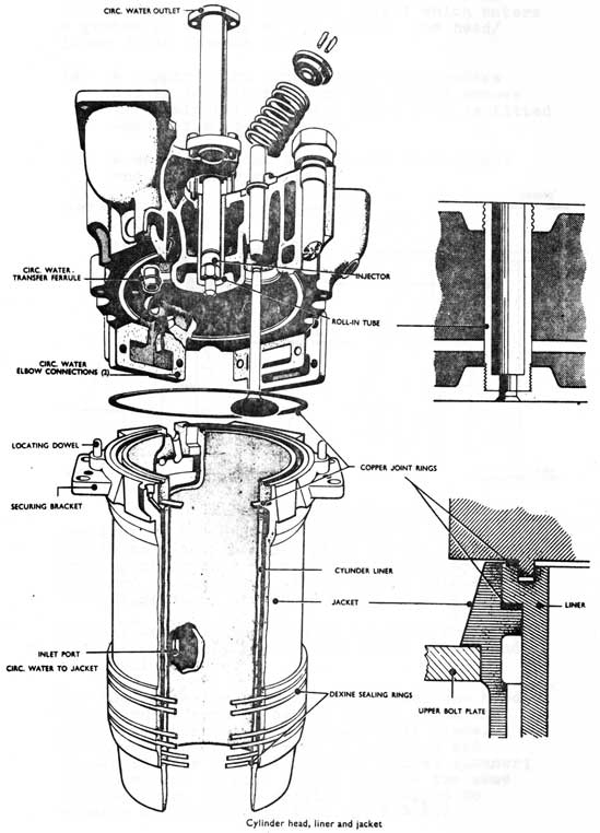
(3) Cylinder Liners and Jackets. The cylinder liners are of forged steel with chromium plated bores. The water jacket is formed of three cylindrical steel sections welded together and subsequently machined. Water sealing between the liner and jacket is achieved by a copper joint ring fitted under the liner flange, and two dexine rings fitted in grooves around the lower end of the liner.
The jacket and liner assembly seats on to the upper bolt plate, and is located by two dowels which engage two drilled lugs on the top of the jacket. The assembly passes through the lower bolt plate and is sealed by four dexine rings.
Cooling water passes into the assembly via an inlet port into the jacket, and thence to the cylinder head via elbow pieces, and a small ferrule.
NOTE: At the lower end of the liner, two 1/2 in. holes are bored for the piston supporting gear. One of these holes is marked 'FRONT', When inserting the liner into the jacket these holes must be fore and aft with the marked hole facing the free end.
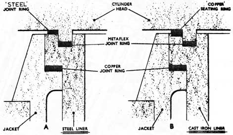
(4) Cylinder Heads. The heads are of close-grained high duty cast iron, and contain the inlet and exhaust ports and valve seats, and the fuel injector tube. The underside of the head is formed to provide a circular spigot which enters a groove in the top of the liner. The head/ liner joint is made by:
(a) A copper joint ring in a shallow recess cut in the liner around the spigot groove (C.I. Liners). A steel joint ring is fitted when using steel liners.
(b) A metaflex joint between the head spigot and the liner groove.
Cylinder liners, fitting of joint rings.
Two lugs on the head are machined to engage dowels on the upper bolt plate of the cylinder framing after they have passed through the cylinder jacket lugs. These dowels maintain the alignment of the whole cylinder unit.
Cooling water is supplied to the head from the cylinder assembly via the two elbow pieces and the small ferrule.
The fuel injector tube is rolled into the head. Each head is secured by six 1 1/2 in. studs and nuts which screw into the lower bolt plate. The lower end of each stud is extended and shaped to take a 5/8 in. B.S.F. socket spanner; the upper end is also shaped to take the same size spanner, and is drilled and taped to receive a lifting bolt (5/8 in. B.S.F.)
Pressure Tests - C.W. passages 60 p.s.i.; Underside and Air Start passages 1500 p.s.i.;
13-14
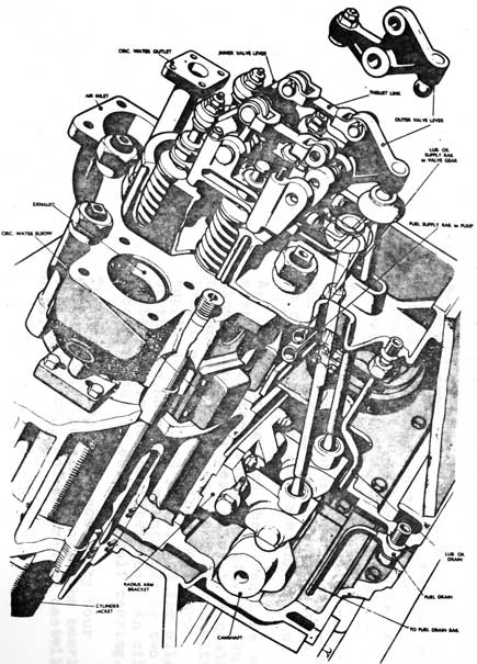
Cylinder and valve gear, left-hand bank
13-15
CYLINDER HEAD AND VALVE GEAR
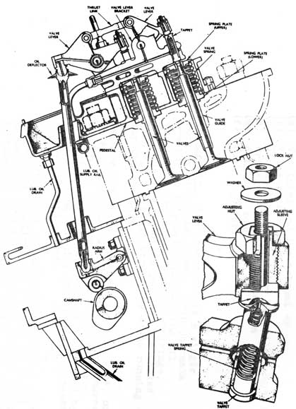
VALVE GEAR
13-16
Cylinder head mountings. The head is machined to take the following fittings:
(a) Two inlet and two exhaust valves.
(b) Valve rocker gear
(c) Circulating water elbow pieces and ferrule
(d) Pressure indicator connection
(e) Air start mounting
(f) Fuel injector.
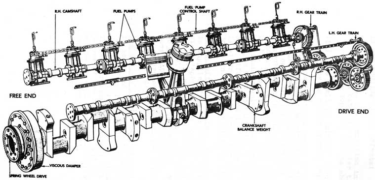
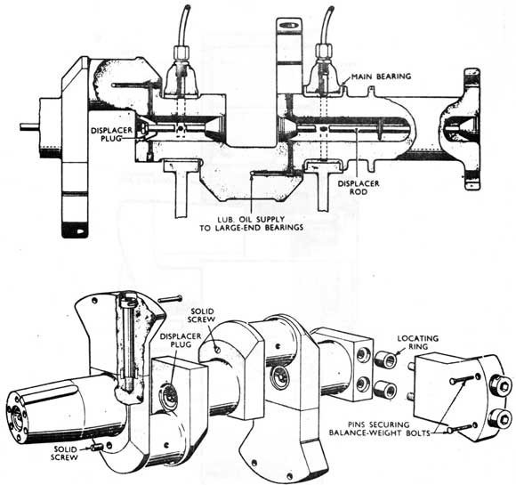
(5) Crankshaft. The crankshaft is a single forging of special steel. Main journals are hollow to provide lubricating oil supplies to main and large end bearings. The ends of the hollow journals are sealed by displaces plugs secured by studs running through the bore.
Balance weights are secured to crank webs, one to each crank throw. The weights are secured by through bolts which screw into the webs. Correct position of the weights is assured by steel locating ferrules fitting into recesses in the webs and weight.
The drive end of the shaft is forged and machined to form the coupling, and a collar is formed between the last engine bearing and the coupling to take the camshaft drive wheel. The free end of the shaft is tapered to take the viscous damper and spring wheel drive for the pumps.
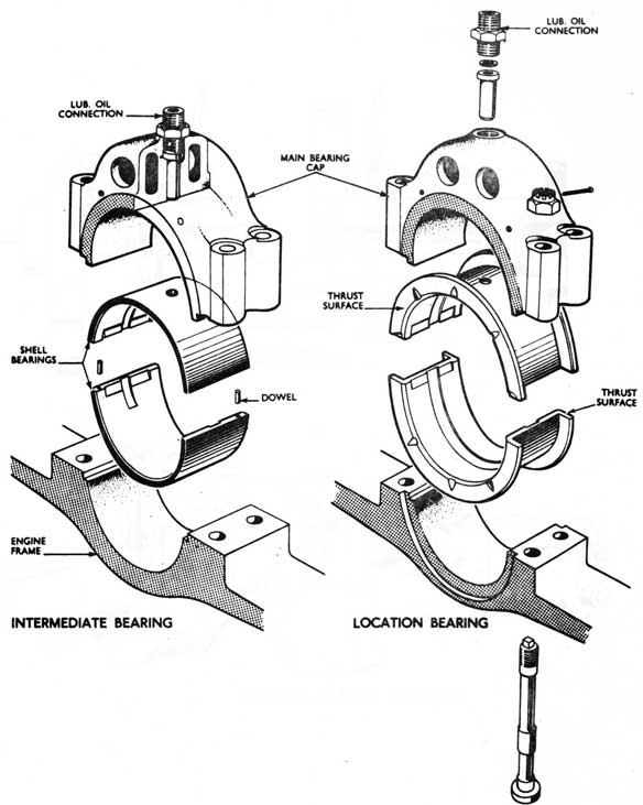
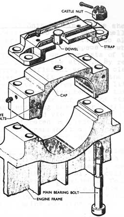
(a) Main Bearings. In the submarine application of the A.S.R.I., nine main bearings are fitted within the engine crankcase. The journal at the No. 10 position is left unsupported due to inaccessibility.
The main bearing housings are formed in the transverse members of the engine bed, and boring of all supports is carried out in one operation with bearing caps on.
All main bearings are shell bearings consisting of steel shells of 1/2 in. thickness lined with copper lead alloy to a nominal thickness of 0.060 in., and plated with lead tin alloy. Bearing shells are supplied in matched pairs, and the alignment of the two halves is maintained by two fitted dowels at the interface. An oil groove is cut in each top half bearing.
The bearing caps are secured by four
through bolts passing through the bearing housing and cap, and secured by castellated nuts.
13-17
GENERAL ARRANGEMENT MOVING PARTS
13-18
The shell is prevented from turning in the housing by two effects:
(i) The lub. oil connection in the
cap is extended to enter the hole
in the top half bearing shell.
(ii) The shell is 'nipped' into the housing by the bearing cap.
It is vital that the amount of nip applied is within limits as excessive nip will distort the shell, and insufficient nip will cause the shell to fret on the oil connection which could result in the shell rotating. The crankshaft is located axially by No. 9 main bearing. This bearing has end flanges which are whitemetal lined to a depth of 0.060 in. No. 5 main bearing also differs from the others in that it is wider since it spans the vertical joint in the engine cylinder frames.
(b) Crankshaft Lubricating. Lubricating oil is supplied from a manifold in the bedplate via a separate pipe to each bearing cap. The main journal, crankwebs, and large end journal are drilled to pass oil to the adjacent journal and bearing. No. 5 bearing does not supply any large ends, the displaces plugs are omitted, and the oil returns direct to the sump.
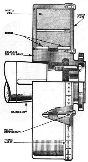
(c) The Viscous Damper. The viscous damper is keyed and bolted to the free end of the crankshaft. Its function is to reduce the torsional vibrations of the crankshaft. These vibrations are caused by the firing pulses of the cylinders, and if they become excessive will lead eventually to fatigue failure of the crankshaft.
13-19
MAIN BEARINGS
13-20
CRANK SHAFT DETAILS
13-21
VIBRATION DAMPER
13-22
Spring wheel drive
13-23
The damper consists of a casing bolted direct to the crankshaft, which contains a heavy inertia ring free to rotate within the casing. The clearance between the casing and the ring is filled with a constant viscosity fluid. As the engine rotates the inertia ring will revolve at constant speed equal to the mean speed of the crankshaft. Any torsional vibration superimposed on this mean speed will cause relative motion between the inertia ring and the damper casing. This relative motion will create viscous shear forces within the fluid, thus energy will be absorbed by the fluid, and converted to heat by viscous friction effects, thus energy which would have been absorbed as vibration, is now converted to heat, and consequently the degree of vibration must be reduced but not eliminated. The vibration damper casing is formed with a collar at the free end to take the spring wheel drive.
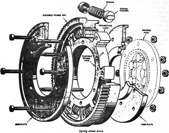
(d) Spring Wheel Drives. The spring wheel is fitted to isolate the reduced torsion: vibrations of the crankshaft from the engine pumps. It consists of a hub, which is bolted to the front of the damper, a toothed rim around the hub, and sets of springs which separate the hub and rim, In this case the energy of vibration is absorbed by the springs. The rim is lubricated by oil supplied from the engine system. Oil is sprayed into the spring wheel drive, and deflector plates ensure penetration of oil through the rim axial clearance to the hub assembly.
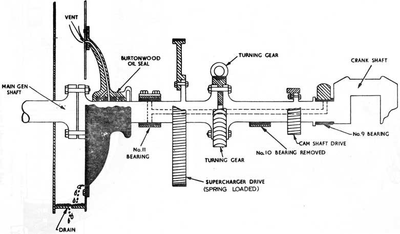
(e) The Stub Shaft. At the drive end of the crankshaft, a stub shaft, is fitted to provide the following:
(a) Shaft connection to the Generator.
(b) Engine/Generator sealing arrangement.
(c) Supercharger drive wheel.
(d) Turning gear wheel.
(e) Bearing support to compensate for removal of No.10 Main Bearing.
13-24
DIESEL SHAFTING
FROM NO. 9 BEARING TO MAIN GEN. COUPLING
13-25
No. II Main Bearing
Crankshaft Labyrinth and Seal
13-26
(f) No. 11 Main Bearing. The shells are identical to other main shells, but the bearing cap is modified to allow removal from the confined space in which it is sited. The cap consists of two parts, the cap and the strap. By removing the strap sufficient vertical clearance is given to lift and remove the. cap. Small eyebolts are provided for lifting. The shells are prevented from turning by a dowel passing through the strap and cap, and engaging the upper shell. Lubrication is provided via the hollow stub shaft. A perforated displacer plug is fitted at the crankshaft end, and a solid plug at the generator end.
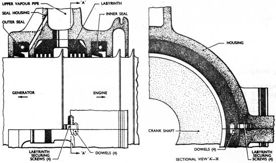
(g) Crankshaft Seal. The housing is made in two halves and contains two split spring-loaded composition seals, and one split labyrinth type seal. Location of the labyrinth is provided by four set screws The and dowels. The drain from the centre of seal unit is led to the void space between the engine and generator.
Labyrinth clearance - 0.0015 to 0.0045 in.
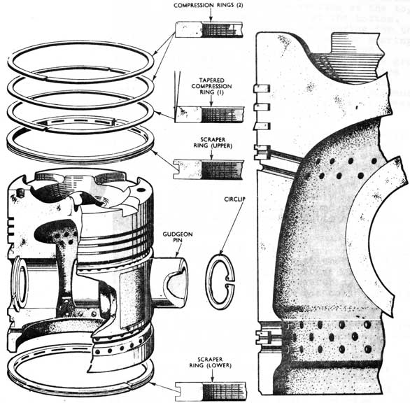
(6) Piston Assembly. The piston is cast in Y alloy. The crown contour gives valve clearance, and air swirl. Radial expansion of the piston is allowed for by reducing the diameter at the crown. Two tapped holes are provided in the crown for lifting eyebolts.
There are five piston rings:
2 parallel compression
1 tapered compression and
2 scrapers (1 above and 1 below the gudgeon pin).
Oil removed from the liner bore by the scraper rings is drained through holes drilled through the piston skirt in the ring grooves. Two bosses are cast in the skirt for the fully floating gudgeon pin which is retained axially by circlips.
13-27
PISTON ASSEMBLY
13-28
Note: The gudgeon pin is only fully floating when hot.
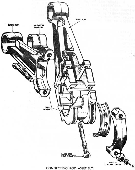
(a) Connecting rods are fork and blade type, each pair of pistons transmitting power to one crank throw. The fork rod is of H section at the top, and separates into two pillars at the bottom. The large end block contains the bearing for the fork rod, and forms the journal for the bearing of the blade rod. The bore and blade rod
journal surfaces of the large end block are ground with halves assembled, temporary steel strips being used to allow for the thickness of the feet of the forked rod. Longitudinal alignment is assured by two gunmetal rubbing strips pressed into grooves at each end of the block.
The shell bearings are of steel, approximately 1/4 in. thick lined with copper lead alloy, and plated with a thin lead flashing. Two dowels prevent movement of the shells within the housings.
The fork rod and large end assembly are held together by four 1 in. bolts and castellated nuts. The nuts are tightened until a stretch of .014" is obtained.
The blade rod is of H section, and the top half bearing housing is integral with the rod. The shell bearing is of phosphor bronze, located by side flanges and dowels. The securing bolts are similar in design to the fork rod bolts but are of larger diameter.
Small end bushes are of phosphor bronze and are a drive fit in the rod housings. Both rods are made of forged nickel steel.
Lubrication of the whole con-rod assembly is supplied via a hole in the crankshaft large end journal through holes in the shells, and ports in the housings and rods. Drainage back to the sump is by natural leakage.
(7) Valves and Valve Gear. The inlet and exhaust valves are similar in design but the exhaust valve has a stellited face. The effective diameter of the inlet valve is 2.8134 in., exhaust valve is 2.4383 in.
13-29
13-30
All four valves are of nickel chrome tungsten
steel working on seats machined in the cylinder
head casting, and in cast iron guides driven
into the head from the top. The valve springs
and rocker gear are mounted in an aluminum alloy
pedestal bolted to the top of the head. A
gaskoid joint is fitted at the interface. Valve
spindles are grooved at the top to take conventional
split collets. The tappets are spring-loaded
to maintain constant contact between the valve
lever tappet and the valve stem, and so obviate
'valve clatter' and wear.
The rocker gear tappets are mounted in valve levers which operate in pairs. The motion of the outer lever is transferred to the inner lever via a thrust link. Tappet adjustment is carried out by rotating the adjusting sleeve, which can be subsequently locked by a nut and washer.
The thrust link pins and valve lever pivots are of case hardened steel working in phosphor bronze bushes. The outer end of the outer valve lever contains a ball plug which engages with the concave end of the push rod. The lower end of the push rod sits in a concave in the radius arm. The radius arm is mounted on a support bracket bolted to the camshaft through boltplate. The radius arm is operated by the camshaft.
Lubrication of the valve and rocker gear is by oil supplied from a rail running along the engine. A pipe supplies oil to each pair of valves lubricating the tappets, valve lever fulcrums, thrust link pins and ball plug. A second pipe supplies the radius arm pivot and ball cup, this pipe is supplied from the adjacent camshaft bearing.
Valve Timing:
Inlet valve opens
- 32° B.T.D.C.
Inlet valve closes
- 46° A.B.D.C.
Exhaust valve opens
- 56° B.B.D.C.
Exhaust valve closes
- 22° A.T.D.C.
Valve overlap - 54°
13-31
13-32
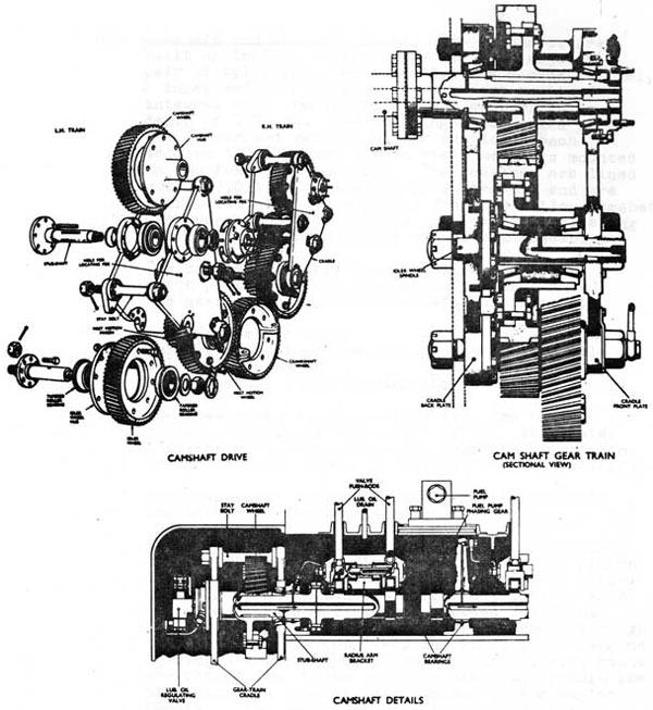
(8) Camshaft and Camshaft Drive. The camshafts are
built up in four sections one for each adjacent
pair of cylinders. Each section has 6 cams (2 fuel,
2 inlet and 2 exhaust). The cams are machined
integral with the shaft, and are carburized to a
depth of 1/32 in. The couplings are marked with
the number and handing of the section. Each
section is supported in two shell bearings mounted
in the fuel pump supports. The bearings are lined
with a 0.015 in. thickness of whitemetal and are
lubricated with oil supplied from the hollow camshaft.
One pump support is drilled to provide lubricating
oil supply to the adjacent radius arm assembly.
The camshaft is driven by a hollow stub shaft which protrudes from the camshaft gear train. The gear train for each camshaft consists of:
(a) Crankshaft wheel
(b) First motion wheel and pinion on same axle
(c) Idler wheel
(d) Camshaft wheel driving the stub shaft.
The wheels, hubs and bearings etc. are housed
between two plates (front and back). The plates
together with stay bolts etc. form the gear train cradle, and one cradle is fitted for each camshaft.
The crankshaft wheel is bolted in two halves to the collar on the crankshaft.
All wheels are of nickel steel and the teeth are single helical. The first motion wheel and pinion and the idlers are 'free' and are bolted to hollow hubs which run on tapered roller bearings at each end of a fixed shaft secured between the front and back plates. These shafts are extended through the back plate to form securing studs to the engine framing. Between the two main plates, 3 stay bolts are fitted, and these are also extended through the back plate to form securing points on the engine framing. The back plate is also fitted with
three location bolts, thus eight securing points are used to fix the train to the engine frames.
The camshaft wheel of each train is bolted to a hub which is keyed to the stub shaft. The stub shaft runs in tapered roller bearings housed in the cradle plates.
13-33
Each camshaft wheel is drilled axially at a point near its periphery. At a point in the front plate a further hole is drilled, and an alignment peg can be fitted to lock the train for refitting or timing operations.
The tapered roller bearings of the train are lubricated internally by an oil supply through the fixed shafts which are drilled and ported to take banjo connections. The stub shaft is supplied from a face to face fitting which incorporates a regulating valve since this also supplied the camshaft.
All gear train wheel surfaces are lubricated by jets supplied from the main lubricating oil system.
In order to prevent axial float of the gear wheels when the train is hot, the bearings are given a degree of axial nip when cold (0.001 - 0.002 in.). This nip is adjusted by steel distance washers fitted between the front plate and the outer bearing. The camshaft wheel nip is adjusted by a similar washer fitted between the front plate and the oil retaining cover. A further check on the nip is carried out by measuring the torque required to turn the wheels - this should be between 5 - 10 in. lb.
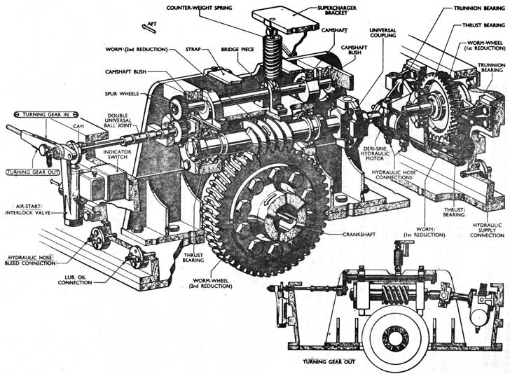
(9) Turning Gear. The turning gear is situated at the drive end of the engine between the camshaft gear train and the drive to the supercharger. Pressure from the ship's hydraulic system is supplied to a Deri-Sine motor which operates the turning gear through two stages of worm and wormwheel reduction, the second stage wormwheel being fitted to the crankshaft. The overall speed reduction obtained is 1 : 95.6; thus it is possible to turn the engine at very slow speeds. For emergency use, the motor can be operated by means of a hand pump. Engagements of the turning gear is effected by means of a lever which operates a shaft fitted with two cams, which engage the underside of two brackets, which in turn carry a suspension box. This box houses the second reduction worm and shaft. The second reduction wormshaft and the first reduction wormwheel shaft are in line and connected by a universal coupling, one member of which is free to move laterally on the splined end of the first reduction wormwheel shaft. The first reduction assembly, including the motor, is suspended in trunnion bearings to permit slight tilting of the assembly.
13-34
Turning Gear
13-35
The counter-weight spring is designed to balance the weight of the suspension box in its approximate mid-position; the cams therefore press the lower rubbing strips-downwards to engage the turning gear, but support the entire weight of the box, through the upper rubbing
strips (contained in the brackets), when the turning gear is 'out'.
When the turning gear is engaged, the cam operated air start interlock valve will be thus no starting air can be supplied to the air
start system.
Lubricating oil to the assemblies is supplied
from the L.O. priming system to a stand pipe
in the engine bed adjacent to the turning gear. From this pipe flexible pipes supply oil to the first and second reduction stages.
The first reduction stage is supplied by a flexible lead taken to each of the two tapered roller bearings which support the wormwheel shaft. After leaving the bearings the oil floods the casing and thus lubricates the gears and the wormshaft bearings.
The second reduction stage is supplied by a flexible pipe to a connection on the coupling end of the worm box. Oil is supplied from there by ports to the bearings, and by a perforated tube to spray the gears.
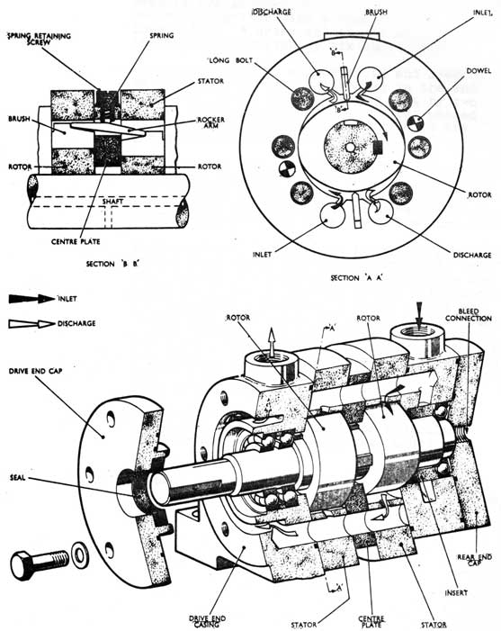
(9a) Turning Gear Motor. The motor is coupled to the first reduction worm shaft, and connected to the hydraulic system through wire-wound flexible hoses.
Motor details - Type.
Deri-Sine s/5-1
Max. working pressure
2000 p.s.i.
Max. speed
2500 rev/min.
Corresponding engine speed
26.14 rev/min.
13-36
Hydraulic Turning Motor
13-37
The fixed portions of the motor consist of five principal components; a centre plate, two stators, a rear end casing and a drive end casing. These members are located radially by two dowels, and secured, together with a rear end cap, by six long bolts. A drive end cap is also secured to the drive end casing by six short bolts.
The motor shaft is supported in and located axially by ball bearings housed in the end casings. It is driven through keys by two rotors of double-cam form which are phased at 900 to one another, and operate in the pressure chambers of the stators.
Depending on the position of the control valve, hydraulic pressure is led to either the rear end or drive end casing and thence through axial channels to two ports in each pressure chamber. Similar provision is made for the return oil.
To form a seal between the hydraulic pressure and return flat steel brushes are provided, two for each rotor. The brushes bear lightly on the curved surfaces of the rotors due to the influence of the hydraulic pressure. A light spring and rocker arm is provided to ensure initial contact of the brushes upon the rotors when starting the motor. The contact ends of the brushes are profiled as shown to ensure that the resultant pressure of the brushes on the rotors is sufficient only to obtain light contact.
Each motor is provided with a 'bleed off' connection which is led to the hydraulic replenishing tank via a spring-loaded ball valve.
Control valve - double acting piston type; limiting flow valve fitted on inlet side.
13-38
(10) Air Induction-Superchargers
Air Manifolds, one for each bank, are made of four aluminum alloy sections, running the full length of the engine.
At the free end they are blanked and at the drive end are connected to the outlets from the supercharger air coolers. To ensure pressure balance the two manifolds are cross-connected at the cooler outlets.
From the manifolds branch pipes lead to the cylinder heads, these are made of aluminum alloy, (when renewing they should be replaced with steel pipes) only the two end pipes are in one piece, the other six are cut in halves and joined with a rubber sleeve to facilitate fitting and lining up. (Mod. No. 303). A boost pressure gauge and a Rototherm thermometer are fitted on
each manifold. Two Air Inlet valves are also
fitted to each manifold to provide an air supply when unsupercharged. Action of these valves is automatic but hand control gear is fitted to prevent valve flutter.
Superchargers
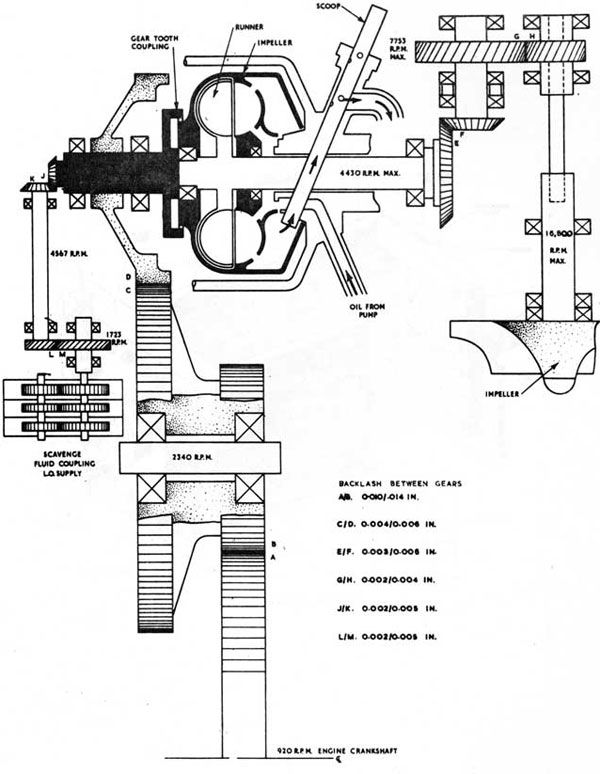
The Godfrey Supercharger is a centrifugal type blower driven through gearing from the engine crankshaft. The drive, which incorporates a fluid type coupling, is stepped up in four stages from 920 rev/min. at the crankshaft to a maximum of 16,700 rev/min. at the supercharger (ratio 18.15 : 1). This speed ratio can be varied by the operation of a scoop trimmer on the fluid coupling.
The impeller wheel is a fully machined aluminum alloy forging consisting of a hub around which the integral blades are equi-spaced. The blades are tapered to the tips and blend into guide vanes at the centre to induce the air flow into the supercharger. Air discharged from the impeller passes through a displacer ring fitted in the casing. The impeller is keyed to its shaft and retained by a nut and tab washer. Support for the assembly is given by a double ball bearing at the impeller end and a roller bearing at the drive end. The bearings are force lubricated, leakage of oil into the impeller being prevented by a gland comprising a scroll seal and a carbon seal assembly.
13-39
Inlet Valve, Air Induction System
13-40
The drive shaft from the final step up gears is coupled to the impeller shaft and is serrated at both ends. It is also necked so that it will fracture should defects develop in the supercharger.
(10a) Supercharger Drive. The drive from the crankshaft to the supercharger is taken through the following:
(1) From a spring-loaded gearwheel on the crankshaft stub shaft to the smaller of two gearwheels on a layshaft assembly which is supported on the engine framing.
(2) From the larger wheel on the layshaft to an input gearwheel keyed to an input shaft in the supercharger casing.
(3) From the input shaft to a bevel gear drive, via a toothed coupling, a fluid coupling and an output shaft.
(4) From the bevel gear drive to the final step up gear drive to the supercharger.
(10b) Fluid Coupling. The fluid coupling (hydro/ kinetic transmission) enables the speed of the supercharger to be varied over a wide range by the operation of a lever controlling a scoop trimming mechanism. The drive member (impeller) of the coupling has a number of radial vanes and is contained within and attached to a scoop chamber, which is driven at constant rotation with the engine crankshaft through the toothed coupling on the input shaft. The driven member (runner) is similarly vaned and is bolted to the output shaft, which passes through the axis of impeller and scoop chamber to transmit the drive to the bevel gear drive.
Oil enters the impeller through ports in the hub and is pumped in a continuous flow into the scoop chamber via ports in the periphery of the impeller. The oil circulates in the form of a vortex to the runner which is thereby set in motion to transmit the drive to the output shaft. A scoop tube, housed in the supercharger casing, can be lowered into or withdrawn from the stream of oil rotating in the scoop chamber. When the scoop is lowered, oil is swept up the tube and transferred to the gearbox sump; the consequent reduction in the mass
of oil in the working circuit has the effect of increasing the slip and therefore reducing the speed of the output shaft. Conversely, withdrawal of the tube allows a greater mass of oil to remain in the working circuit thereby reducing the slip and increasing the speed of the output shaft.
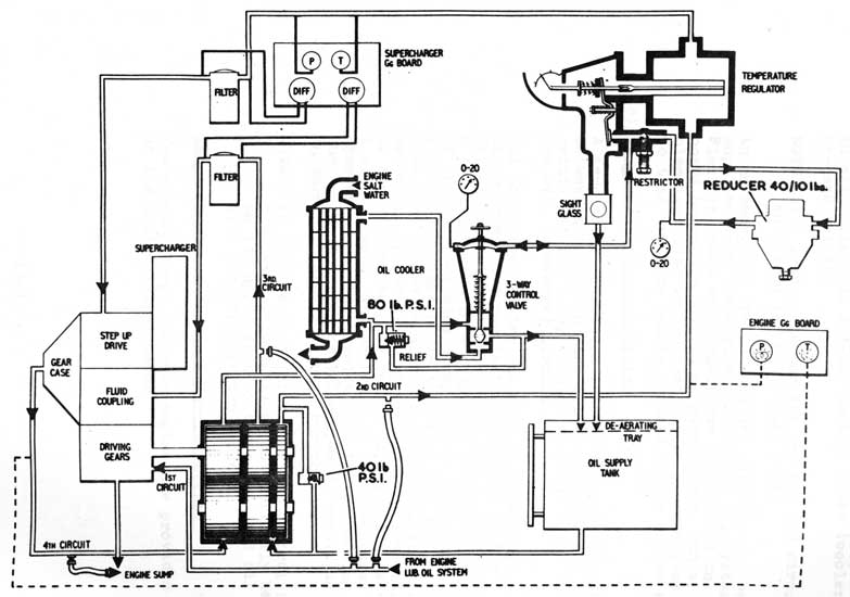
(10c) Lubrication and Fluid Coupling Oil Systems
Oil for lubrication of the gears and bearings and for the operation of the fluid coupling
flows through four separate circuits. The
first circuit is supplied from the engine system and the other three from a pump assembly which comprises three individual gear type pumps. The pump assembly is driven through gearing from the outer end of the input shaft.
1st Circuit - Supplied from engine system at 30 lb/sq.in. to:
(a) Layshaft gears and bearings.
(b) Oil pump drive gears and bearings.
(c) Input shaft bearings.
Oil drains to engine sump.
2nd Circuit - Supplied from section of oil pump at 5.75 gal/min. at 40 lb/sq.in. to:
(a) Serrations at each end of supercharger drive shaft.
(b) Supercharger shaft bearings.
(c) Bevel and final step up gears and shaft bearings.
(d) Output shaft bearing (outer).
Oil drains to gearbox sump.
Circuit - Supplied from section of oil pump at 9 gal/min. to:
4th Circuit - In this circuit the third section (scavenge) of the oil pump sucks the oil from the gearbox sump and discharges it to an oil supply tank via a 80 lb/sq.in. relief valve, an oil cooler and a 3-way control valve (cooler by-pass valve).
NOTE: The gear pumps for the 2nd and 3rd circuits suck from the oil supply tank.
In an emergency the 2nd and 3rd circuits can be supplied from the engine lubricating oil system. Flexible hoses and connections are carried on board to enable this to be carried out, and a blanking plate is provided on the gearbox sump so that the sump can be drained to the engine sump.
(10d) Temperature Control System
A temperature regulator in the 2nd. oil circuit between the pump and the filter controls the setting of the 3-way (cooler by-pass) valve in the 4th. (scavenge) circuit.
Oil discharged to the 2nd circuit flows past a thermo sensitive rod in the regulator to the filter, and also via a 40 - 10 p.s.i. reducer and a throttle screw to a diaphragm chamber at the top of the spring-loaded 3-way valve. When the oil temperature rises above the regulator setting a leak port in the regulator outer casing is automatically opened allowing the oil from the outlet of the reducer to pass to the supply oil tank via a sight glass. The pressure in the diaphragm chamber of the 3-way valve then falls, causing the spring to move the valve upwards resulting in more oil passing through the cooler.
NOTE: In the event of failure of the control system the 3-way valve will be automatically held on its upper seat by the spring and all oil will pass through the cooler.
Temperature and Pressure Warning Lights
Two warning lamps for each engine are provided on the engine gauge board:
13-46
(1) One lamp is extinguished when the pressure in the 2nd. circuit falls below 30 p.s.i.
(2) The other lamp is extinguished when the temperature in the scavenge suction line exceeds 205°F.
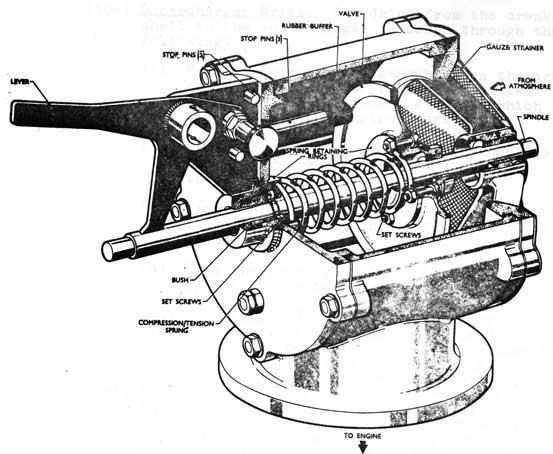
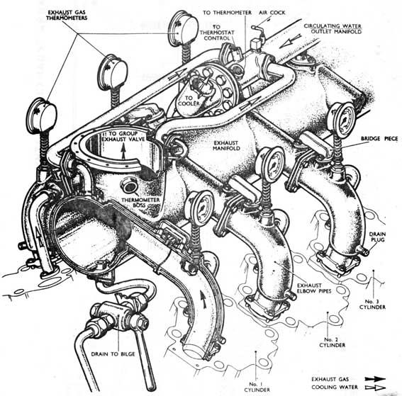
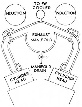
(11) Exhaust System
Exhaust gas from each cylinder is led to a manifold running the full length of the engine. The manifold is in three sections each receiving gas from it's adjacent cylinders. The exhaust bends and manifold sections are formed of steel pipes surrounded by water jackets made in halves and welded.
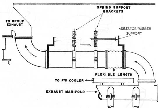
Cooling water is supplied from the cylinder heads via a stand pipe on each head to the exhaust bend. Water then passes to the manifold through bridge pieces. From the manifold, water is led to the cooling water outlet manifold. A trunking led from the for'd end of the manifold conveys the exhaust gas to the group exhaust valve. This trunking incorporates corrugated expansion sections, and is supported by a spring pipe clip. The group exhaust valve is water cooled, the water being supplied from the engine distilled water system.
The group exhaust valve incorporates a grinding device since it has a metal seat in the gas stream.
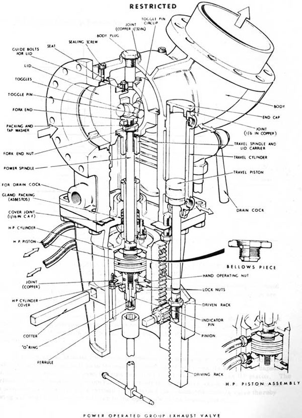
The group exhaust valves on ONONDAGA and OKANAGAN are air operated sluice valves, designed for quick shutting in the event of snorkel muffler valve failure.
They have the following advantages:
a. The bore is increased to 8 in.
b. The valve is not in the gas stream when open.
c. The resistance to shock is increased
d. It is controlled from the starting platform.
The valve consists of a double faced (two lids) sluice valve operated by an external air travel piston through a rack mechanism.
The valve is locked when in the shut position by means of two toggles, operated by an HP piston and power spindle; which force the two lids against the seats. In an emergency both the operating and locking gears can be worked by hand.
13-47
Exhaust Manifolds
13-48
EXHAUST MANIFOLD COOLING ARRANGEMENT
INTERNAL EXHAUST ARRANGEMENT
13-49
Air Control of Group Exhaust Valve
13-50
Air Control of Group Exhaust Valve
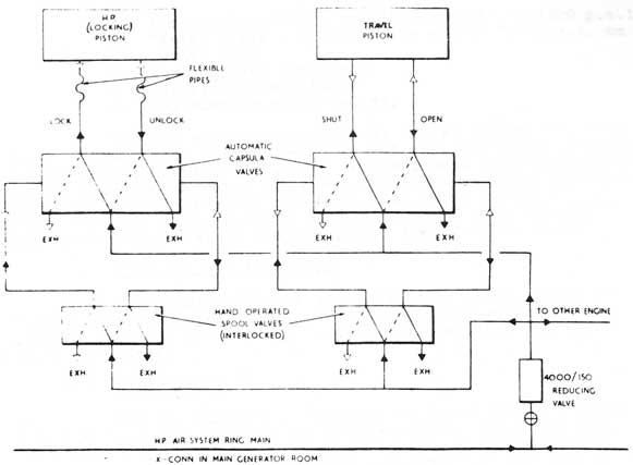
(11a) DIAGRAMMATIC ARRANGEMENT OF CONTROLS FOR AIR
OPERATED GROUP EXHAUST VALVE
The controls for the travel and HP pistons are identical, each consisting of a hand operated spool valve and an automatic air operated capsula valve. The spool valves are interlocked to ensure correct sequence of operation.
In Fig. the air flow through the valves is shown with the group exhaust valve shut and locked. In this position the air flow through the spool valves holds the capsula valves in the position which permits air to pass to the shut side of the travel piston and the lock side of the HP piston.
When the group exhaust valve is to be opened the locking spool valve is moved to the unlock position, when air will pass through the spool valve and move its associated capsula valve thereby allowing air to pass through the latter to the unlock side of the HP piston. The interlock is now moved to allow operation of the other spool valve which when moved to the open position allows air to pass through it to operate its associated capsula valve thereby allowing air to pass through the latter to the open side of the travel piston.
13-51
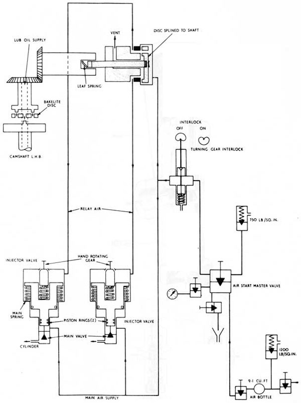
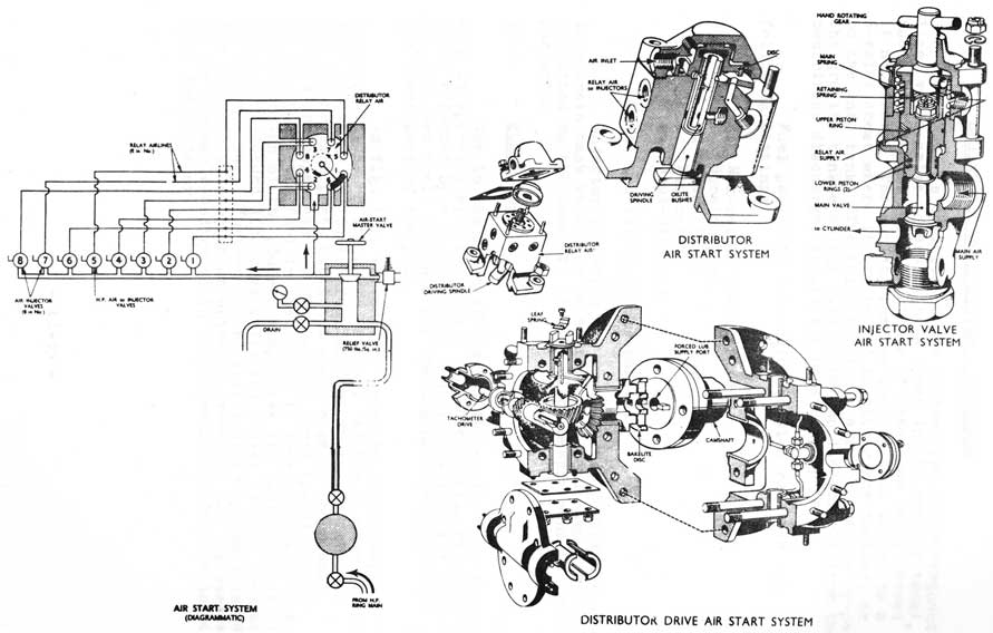
(12) AIR START SYSTEM
The system consists of:
a. Air start bottle - relief valve set to 1200 p.s.i.
b. Master valve - relief valve set to 700 p.s.i. on outlet side
c. Turning gear interlock
d. Air start distributor
e. Cylinder injector valves.
The air start distributor is driven by the left hand bank camshaft, and directs relay air at full air start pressure to the injector valves fitted to the left hand bank cylinders in firing order. The relay air opens the injector valve and allows starting air to enter the cylinder. The relay system is used since the full flow of air is not required to pass through the distributor and smaller components can therefore be used.
Turning Gear Interlock
The interlock valve is operated by a cam behind the turning gear engaging lever. With the turning gear 'in', a plunger cuts off the air supply to the distributor and the injector valves.
Distributor
The distributor is driven from the camshaft through bevel gearing and a tongue and groove joint. The drive also provides a worm and wormwheel drive to the engine tachometer. Lubrication of the parts is by oil supplied from the hollow camshaft.
The distributor disc is splined to the driving spindle and is held off the block face by a leaf spring fitted in the tongue and groove coupling. When relay air is admitted to the top of the disc the latter is held on to its seat against the leaf spring, and relay air passes through a hole in the disc to the appropriate injector valve. At the same time the relay air of the other seven injectors is vented to atmosphere, via a recess on the underside of the disc, and past the drive spindle.
Injector Valve
The injector valve consists of a spring-loaded poppet valve operated by a differential area piston. Relay air acts on the larger area and will open the poppet valve against the spring force plus the main air force. Main air is thus admitted to the cylinder.
A T-handle is fitted which can be engaged to rotate the poppet valve on its seat should it be leaking through dirt etc.