C.F. 'O' Class Submarines - Sea Water Systems, describes the sea water systems of the Oberon class submarines.
In this online version of the manual we have attempted to keep the flavor of the original layout while taking advantage of the Web's universal accessibility. Different browsers and fonts will cause the text to move, but the text will remain roughly where it is in the original manual. In addition to errors we have attempted to preserve from the original, this text was captured by a combination of optical character recognition and human typist. Each method creates errors that are compounded while encoding for the Web. Please report any typos, or particularly annoying layout issues with the Mail Feedback Form for correction.
TRIM, MAIN, OILY BILGE, FORWARD AND AFTER SERVICES LINES
4.01 INTRODUCTION TO TRIM AND MAIN LINES
To maintain a state of neutral buoyancy and level trim when submerged, the bodily weight of the submarine is adjusted by pumping or flooding water, from or to the sea, into or out of the trimming and compensating tanks. Final adjustments of the fore-and-aft trim are achieved by simply transferring water between the forward and after trim tanks, while the athwartships trim is corrected by regulating the quantities of water contained in "O" tanks by flooding' pumping or blowing. A further condition is when the hull is compressed due to the submarine changing depth. This requirement is met by flooding and emptying "D" tanks.
Normally, the pumping and flooding of water into or out of the trimming and compensating tanks is achieved by a trim pump, or a ballast pump, the pumps displacing water through the trimming and compensating systems, which comprise a trim line and a main line. In an emergency, two motor-driven pumps of a separate system known as the forward and after services may be used.
Arrangements are made for an alternative sea water supply to be led from the main line to a battery cooling system for use when the submarine is stationary.
The trim line allows water to be transferred between the forward and after trim tanks, "O" tanks and the sea and "O" tanks port and starboard.
Through twin control cocks, sited in the control room and other valves grouped in a number of valve chests, all tanks and spaces may be connected to the trim or to the main line.
The principal function of the main line is to enable large alterations to the bodily weight of the submarine to be effected rapidly by flooding or pumping sea water into or out of the compensating tanks.
The larger and more powerful of the two pumps provided (the ballast pump) is sited in the engine room. It is a four-stage, self-priming, motor-driven pump of the centrifugal type. The output of the pump varies according to the head of water against which the pump discharges. A change-over six-valve chest, connected to
4-2
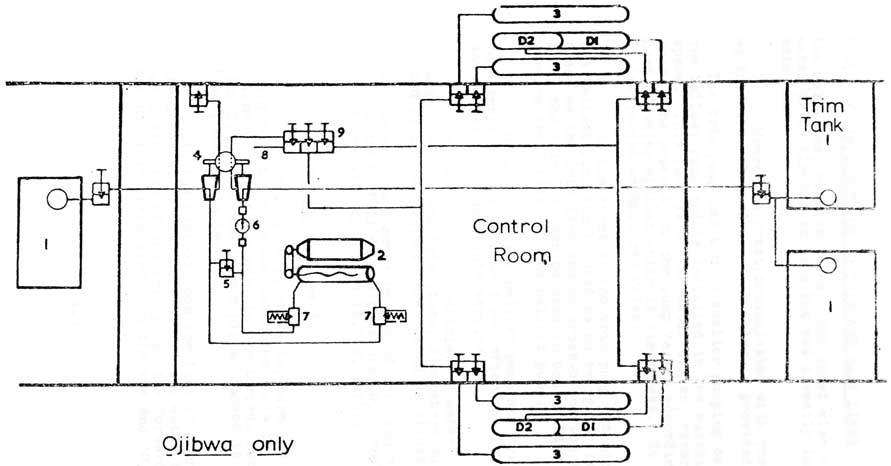
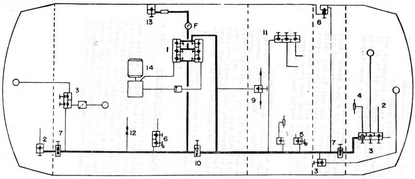
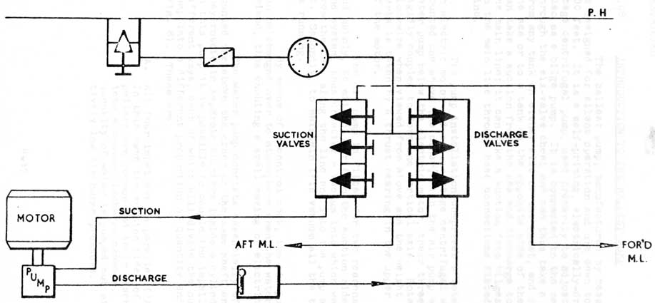
1. TRIM TANKS
2. TRIM PUMP
3. 'O' TANKS
4. CHANGEOVER COCKS
5. TRIM PUMP BY-PASS
6. FLOWMETER
7. RELIEF VALVES
8. MAIN CROSS CONNECTION
9. CONNECTION TO 'D' TANKS
BASIC TRIM SYSTEM
(Fig. 1).
4-3
4.01 INTRODUCTION TO TRIM AND MAIN LINES (CONTD)
the main line, or vice versa. The chest also allows water to be flooded in from the sea directly into the main line.
Where the chest communicates with the sea a 4 1/2 in. bore balanced sea hull valve is provided.
The trim pump has a much smaller pumping capacity than
the ballast pump and is installed in the auxiliary machinery space. This pump is of the motor-driven, reversible Mono type. The capacity of the pump varies according to the head of water against which it discharges. It has a separate 2 1/2 in. screwdown hull sea valve.
In the event of the trim pump becoming inoperative the ballast pump can be used as an emergency trim pump. Also, as the trim line can be cross-connected to the main line, the trim pump can be used in conjunction with, or perform the duties of, the ballast pump.
Should both the ballast pump and trim pumps become inoperative the forward and after services pumps (P and S) may be brought into service.
To measure the quantities of water flowing through the main and trim lines, flowmeters, suitably protected by Spirax strainers are fitted as illustrated.
NOTE: Water should never be pumped into tanks other than those
tested to full diving pressure (O, D and Q tanks) or
those with open tops (A.I.V. tank).
4.02 TRIM LINE (Figure 1)
The trim line is of 2 1/2 in. bore and extends from forward to aft inside the submarine above the main flat. The line terminates forward in the torpedo room, where a 2 1/2 in. S.D. valve and branch pipes connect it to the port and starboard trim tanks.
In the control room the line is connected to twin control cocks. These cocks direct sea water between the pumping circuits of the trim pump, the forward and after sections of the trim line, and the sea and 'O' tanks.
4-4
4.02 TRIM LINE (CONTD)
A by-pass valve fitted across the suction and delivery lines of the trim pump allows 'O' tanks (P and S) to be flooded from the sea and water to be blown from them to sea.
The line terminates aft in the after torpedo room where a 2 1/2 in. S.D. valve connects it to the after trim tank.
4.03 TWIN CONTROL COCKS(Figure 2)
The twin control cock assembly consists of a pair of hollow tapered cocks fitted into a common body casting. A port in each cock registers with either of two portings in the body; water entering or leaving through a connection communicating with the hollow interior of each cock.
4-5
4.03 TWIN CONTROL COCKS (CONTD)
Rotation of a handwheel fitted to the worm shaft turns both cooks in opposite directions simultaneously until a stop or claw cast with one of the wormwheels, engages with a projection on the underside of the steady bearing thus ensuring the correct registering of the cook ports.
A pointer fitted to the spindle of each cook travels over an indicator plate.
The body casting is tested to 400 lb/sq.in., the cocks being require to he watertight up to 200 lb/ sq. in. As a measure of watertightness, the permissible leakage at 400 lb/sq.in. should not exceed one gallon per hour.
4.04 TRIM PUMP (MONO TYPE 4D4/4)
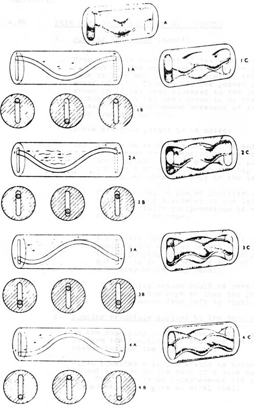
A. Pumping Principle (Figure 3)
If a rope is secured at one end, held horizontally and the free end jerked, up and down, it assumes a series of sine curves, and, although each cross-section of the rope only moves up and down vertically, a ripple or wave motion can be seen travelling horizontally along the rope towards the fixed end.
In theory, a pumping action could be produced by so vibrating a rubber rope inside a hollow tube, the rope having a circular cross-section which is a good working fit in the slot-shaped bore of the tube. Fig. 3, 1A to 4A, illustrates the progressive undulation of one complete sine curve of the rope in the tube while 1B to 4B illustrates the actual movement of a cross-section of the rope at three points. The rope makes a complete axial seal in the tube so that in 1A a pocket of water is trapped between the points 'w' and 'z'.
4-6
The pumping principle
Fig. 3
4-7
4.04 TRIM PUMP (MONO TYPE 4P4/4) (CONTD)
A. Pumping Principle (contd)
From 1A to 2A each part of the rope between points
'w' and 'x' has made contact with the top of the tube in turn and in 4A the point of contact has moved to 'y'. Thus in 4A, the pocket of water shown in 1A has been squeezed to the left while another pocket has been drawn in by the suction caused from the downward movement of the part of rope from 'y' to 'w'.
These are four points to be noted:
(a) As can be seen from 1A, 2A, 3A and 4A, each transverse cross-section of the rope only moves up and down in a vertical plane, but the point of contact with the top of the tube moves progressively to the left.
(b) The water may be pumped positively, being
sucked in and displaced to the left by the progressive reciprocation of each cross-section of the rope.
(c) A complete 360 degree sine curve of the rope would be the minimum length required to a sealed pumping unit (unless both points 'w' and 'z' in 1A touched the top of the tube,
the water would slip back).
(d) The pumping action could be reversed by
vibrating the rope so that the point of contact moves from left to right.
B. Pumping Principle applied to the Mono Pump
In the Mono pump a rigid steel rotor is made to perform the functions or the rope and a rubber stator that of the hollow tube.
First consider a simple stator as shown in Fig. 3A and a rotor in the form of a sine curve within it. The rotor is an interference fit in the rubber stator to give an axial seal.
4-8
4.04 TRIM PUMP (MONO TYPE 4D4/4) (CONTD)
B. Pumping Principle supplied to the Mono Pump (contd)
Now suppose the stator, with the rotor inside it, is uniformly twisted through one complete turn as shown in 1C. The hole then assumes the form of a two-start screw thread while the rotor also assumes a helical or twisted form, but with twice as many coils in the same length as the stator. The cross-sectional form of the rotor and stator and their position relative to one another are unaffected and the rotor still completely seals the hole.
This is the actual form of the rotor and stator in the pump. These two elements have the property of meshing with one another accurately and in such a way that when the rotor is turned, a circular cross-section at tiny point in it's length travels back and forth in a straight line across the corresponding section of the stator, thereby reproducing, relative to the stator, the exact movement of the vibrating rope.
NOTE: The straight line path of each cross-section of the rotor, is, in fact accomplished by a compounding of two motions. The driving mechanism of the pump turns the rotor about its axis, and, due to the meshing of the rotor in the stator, the axis itself simultaneously describes a small circle in the opposite direction.
1C, 2C, 3C and 4C illustrate consecutive positions of the rotor while making one half turn to the stator. 2C is shown opposite 2A, 3C opposite 3A, etc., since in each case the relative position of the rotor in the stator is that of the rope in the tube. Similarly, water in the stator would he trapped by the rotor and displaced as it turned.
4-9
4.04 TRIM PUMP (MONO TYP 4D4/4) (CONTD)
C. General Description
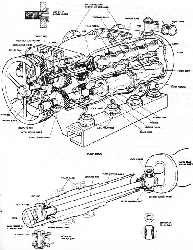
The pumping unit is a chest containing four lengthened elements of the type described, working in parallel. Each of the four rotors is connected to a driving shaft, all four shafts being geared together and driven by three Vee
belts from an electric motor.
By means of a two-way starter, the motor and hence the pump can be reversed so that the two pipe connections into the pump can become either suction or the discharge. Roth pipe connections are fitted with a relief valve set to pass the full capacity of the pump at a maximum pressure of 400 lb/sq.in., the valves commence to lift at 350 lb/sq.in.
In order to develop the necessary discharge pressure at maximum diving depth, the lengths of the rotor and stator are increased so that each element is made up of three of the simple elements as previously described. The discharge head is developed in three stages and the required capacity is obtained by having four of these long elements working in parallel. They are arranged compactly so that their axes form the four corners of a square. The rotors are made of hardened steel and are machined at one end to take a universal coupling.
Each stator consists of a rubber tube moulded to form a two-start thread. This is bonded into a Naval Brass sleeve which has a collar halfway along it for securing in the pump chest.
The gunmetal pump chest is built up of two half castings, each having a pipe connection. The drive end half has a vertical division plate cast integral with it end this divides the chest into two separate chambers when the two halves are bolted together.
4-10
F.O.S/M. H.O. No. 6
1955
MONO TRIM PUMP
4-11
4.04 TRIM PUMP (MONOTYPE 4D4/4) (CONTD)
C. General Description (contd)
Thus when the rotors are turned one way they will take a suction from the drive end half of the chest
and discharge into the closed end hut when the direction of rotation is reversed the closed end pipe connection becomes the suction.
There are two fittings in the chest designed to prevent the rotors from running dry in their stators:
(a) Weirs are fitted round the communicating ports in the stiffening plate and these prevent the water level from falling below the level of the upper two rotors at any time.
(b) Two small nozzles, fitted with strainers, are screwed into the main division plate so that when the pump is in use a small quantity of water constantly by-passes from the discharge into the suction side.
There are four ports in the pump chest to take the driving units and since it would be difficult to form a pressure-tight seal around the coupling rod, the outer driving sleeve is extended to enter a stuffing box and gland in each port.
Since the end of the outer driving sleeve in the pump chest is open, water at discharge pressure can enter the sleeve, which is therefore plugged at the driving end.
The main line extends from forward to aft inside the submarine above the main flat on the starboard side. It is of 4 1/2 in. bore, being reduced in diameter to 4 in. at each end. The line terminates forward in the torpedo compartment and aft in the after compartment.
Three isolating stop valves are fitted on the line, these are 4 in. double-faced sluice valves, one at the forward end of the accommodation space and one at the after end of the motor room, the third is fitted as a cross-connection between the forward and after sections of the main line. This valve is normally kept shut but is opened when the main line is cross-connected with the trim or forward and after services lines, to improve the flow of water.
Five hose connections with shut-off valves are provided on the line. These, with portable hoses, provide a means of flooding or emptying tanks and spaces not permanently connected to the line, washing through bilges and fire fighting. Two of the hose connection shut-off valves are of the S.D.N.R. and flood type and these each have collars pinned and padlocked round the spindle to ensure that the valves cannot be opened to the 'Flood' position without first removing the collars.
The suction valves to the battery tanks and the main line/oily bilge line cross-connection valve are kept padlocked.
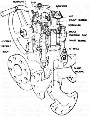
4.06 BALANCED HULL SEA VALVE
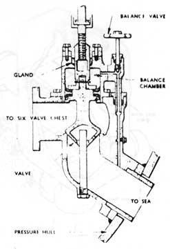
The hull valve (Fig. 6) comprises three main parts - the valves, valve box and the balance chamber. A plunger carrying two sealing rings is formed on the upper end of the dumb-bell shaped valve and works In the bore of the balance chamber. The valve face is machined on the lower end of the valve and has the same area as the plunger. The pressure above the plunger can be equalised with that under the seat by opening a balance valve thus allowing the sea connection to he shut easily when dived deep.
4-14
4.06 BALANCED HULL SEA VALVE (CONTD)
FIG. 6 Balanced hull sea valve
A thrust bearing in the valve bridge prevents the handwheel spindle from moving vertically so that rotation of the spindle raises or lowers the screwed sleeve attached to the top of the valve. Pressure is sealed in the balance chamber by a gland around the screwed sleeve. This can be repacked with both the hull valve and balance valve shut.
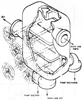
4.07 CHANGE-OVER SIX-VALVE CHEST (MAIN LINE)
The six-valve chest (Fig. 7) has connections to the sea, the main line forward and aft and the ballast pump suction and delivery lines.
A central vertical dividing wall, formed within
the chest, is machined to form Beatings for six balanced
stop valves. The space in front of the central dividing
wall is divided into three transverse passages with two
valve orifices in each compartment. Behind the dividing
well the chest is again divided to form two vertical
passages so that three valves open into each passage. The
suction line of the ballast pump is connected to one vertical
passage, and the pump delivery line is connected to the
second vertical passage. The three transverse compartments
of the chest are connected to the main line forward, the
sea, and main line aft, respectively.
With this arrangement any pumping or flooding operation may be achieved.
Each of the six valves in the chest is similar in design to the balanced hull sea valve.
4-16
SIX VALVE CHEST (MAIN LINE)
DIAGRAMMATIC
4-17
4.08 INTRODUCTION TO THE BALLAST PUMP
The ballast pump, manufactured by Messrs. Drysdale, is designed for silent operation and use down to a depth of 600 feet. It is a self-priming, electrically-driven, four-stage centrifugal pump, used primarily to adjust trim but also as a bilge pump. It is connected to the main line through the six-valve chest and can thus take a suction from any tank on either side of the chest, and discharge to the see or to a tank on the apposite side of the chest; it can take a suction from the sea and discharge to any tank on the main line; it can take a suction from bilges or tanks not on the main line through hose connections fitted on the main line.
The pump installation comprises a rotary air pump, an electric motor and a four-stage centrifugal water pump, mounted one shove the other, with the air pump above and the water pump below the electric motor, their three shafts being rigidly coupled to form one vertical axis. Rotation is anticlockwise when viewed from above and the weight of the rotating parts is taken by a thrust bearing in the upper hearing housing of the motor.
The air pump is fitted for two reasons. Firstly and mainly, to extract air from the suction side of the pump and system, thus creating a vacuum into which water will flow from the tank along the line and into the pump and so prime it. Secondly, to maintain tis vacuum all the time the pump is running.
By means of a control cock, the air pump suction can be changed over to atmosphere when the water pump is fully primed, thus enabling a small saving of electrical power.
The water pump consists essentially of four impellers mounted one above the other on the same shaft and keyed to it. They rotate in separate chambers inside a cylindrical stator. In this pump it is possible to couple the impellers in three different ways, each of which will divide the output of the pump into a different proportion of quantity and pressure (Fig. 8). These are:
A. All four impellers in parallel ('A' in Fig. 8). In this case the suction sides of the four impellers are common and their discharges pass into a common discharge chamber. Thus a large quantity of water is pumped but at a comparatively low discharge pressure.
4-17A
Large Plate on Separate Page
Series/parallel Controls
Operations and Assembly Fig 8
4-18
Series/parallel control indicator gauge
FIG 9
4-19
4.08 INTRODUCTION TO THE BALLAST PUMP (CONTD)
B. Two impellers in series - two in parallel
('B' in Fig. 8). The first and third impellers take their suction from the suction line and discharge respectively to the suctions of the second and fourth impellers, which in turn discharge into the common discharge chamber. By
this arrangement the quantity pumped is less but the discharge pressure is greater than in method 'A'.
C. All four impellers in series ('C' in Fig. 8). In this case the discharge from the first impeller is led into the suction of the second, which in turn, discharges into the suction of the third, and so on through all four impellers, the pressure being increased in each stage but the quantity remaining that discharged by a single impeller. Thus the quantity of water pumped is small but the discharge pressure is very high.
In each of the three methods of operation described above further adjustment of the pump output can be made by varying the speed of rotation, which is controlled by a field rheostat.
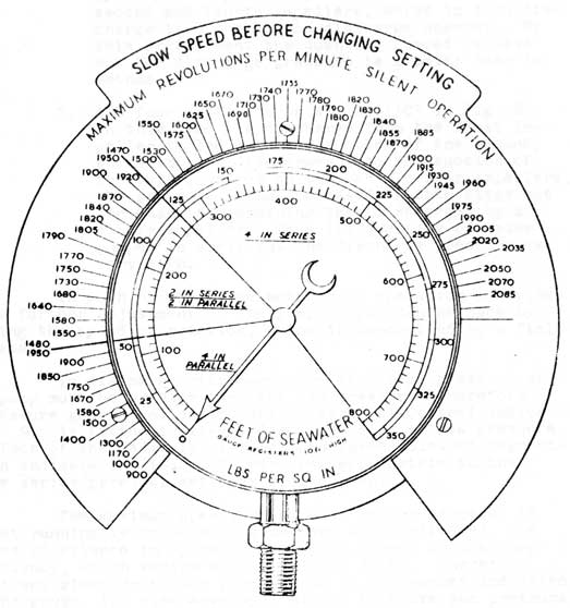
To discharge overboard, the discharge pressure of the pump must be greater then the sea pressure, therefore a pressure gauge, called the Series/Parallel Control Indicator (Fig. 9), is fitted to give a direct reading of sea pressure. The face of the gauge is divided into three coloured segments, which indicate the range of pressures appropriate to the
three series/parallel settings or the pump.
The maximum speeds which must not he exceeded if silent running is to be maintained are also indicated, the degree of silence in operating being dependent on the pump efficiency, which varies with speed and depth. Therefore, if at any given depth the pump is run in the manner indicated by the gauge, its discharge will always be above sea pressure and its operation silent.
4.09 OPERATION
Watchkeeping on the Pump
(1) TAKING OVER THE WATCH
(1) Check water level in the air pump sealing water reservoir; pump control cock 'ON' and shifting cock 'OPEN'.
4-20
4.09 OPERATION (CONTD)
A. Watchkeeping on the Pump (contd)
(2) Turn Auto-klean strainer handle.
(3) Check all six valve chest and hull sea valves shut.
(ii) STARTING
On receiving the order to 'pump'
(1) Open sea discharge valve and appropriate suction valve on the six valve chest.
(2) Check Series /Parallel control lever in correct position in accordance with the Series /Parallel indicator.
(3) Start the pump as follows: Check rheostat handle at zero position. Press starter plunger and move starter handwheel through successive steps until plunger locks the starter handwheel in the 'made' position, taking care that the ammeter is steady at each step before turning handwheel to the next.
(4) Open hull sea valve.
(5) Increase speed of pump as requisite. The speed should be adjusted by the rheostat handle to regulate the pump so that it will overcome the sea pressure and so start pumping. The rising of the pedal, of the discharge
non-return valve, against light pressure of the foot indicates excess pump pressure and that the requisite speed has been reached.
(6) Acknowledge 'pumping' on the pump reply instrument.
4-21
4.09 OPERATION (CONTD)
A. Watchkeeping on the Pump (contd)
Should a change of depth occur while pumping is in progress and the Series /Parallel Indicator shows that another pump setting is required:
(7) Reduce speed of pump to a minimum (i.e. rheostat to zero position).
(8) Reset Series /Parallel control lever to appropriate setting.
(9) Readjust speed as previously described.
This procedure eases the load off the Series/ Parallel cocks and enables the changeover to be made without effort.
(iii) STOPPING
On receiving the order to stop pumping on the pump order instrument or when the flowmeter indicates that an ordered amount has been discharged:
(1) Reduce speed of pump to minimum
(2) Press down lightly on discharge non-return valve pedal and trip the starter, thus ensuring the smooth closing of the non-return valve as the pump pressure falls below sea pressure.
(3) Shut all valves and acknowledge the order on the pump order instrument.
B. Limits of Speed and Output
Since maximum silence of operation can be maintained only by avoiding excessive speeds and output:
(a) Do not exceed the speed marked on the Series/Parallel control indicator.
4-22
4.09 OPERATION (CONTD)
B. Limits of speed and output
(b) When compound suction gauge shows. that the vacuum does not increase, the pump speed should not be increased further or unnecessary noise and power consumption will result.
(c) The loading marks on the ammeter should never be exceeded.
C. Range of Output and Pumping Heads
Total head
Setting of impellers
Rev/min
Ton /hr
Gal/min
Manometric suction lift included in total head
60 ft
4 in parallel
1,500
100
363
25 ft
45 ft
4 in parallel
1,300
120
436
22 ft
80 ft
4 in parallel
1,750
150
545
18 ft
200 ft
2 in series 2 in parallel
1,750
69
250
24 ft
638 ft
4 in series
2,070
10
36.3
28 ft
370 ft
4 in series
1,750
35
126
24 ft
An output of 10 ton/hr against a total head of 700 ft is available when operating in the '4 in series' setting with the air pump in the 'OFF' position without exceeding the motor emergency full load at 2,200 rev/min.
4-23
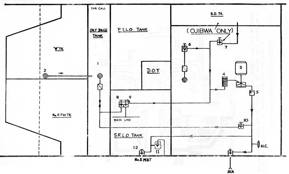
1. Oily bilge Tank
4. Pump strainer
8. Oily Bilge Tank Suction
2. Bilge drain to O.B.T.
5. N.R. Valve
9. M.L. Connection
3. Oily Bilge Pump
6. A.M.S. Bilge Suction
10. Discharge to O.B.T.
7. S.D. Tank Suction
11. 15 P.S.I. Sea Relief
12. 5 M.B.T. Hull Valve
(Figure 10)
OILY BILGE SYSTEM
4-24
4.10 INTRODUCTION TO OILY BILGE LINE
To prevent contamination of the main line by oil a separate line known as the oily bilge line is provided for pumping out the engine room bilges.
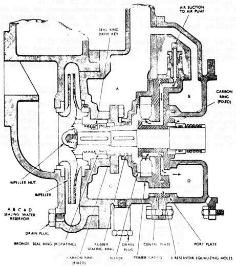
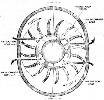
(Figure 11) Impeller and priming rotor assembly
4-25
4.10 INTRODUCTION TO OILY BILGE LINE (CONTD)
The oily bilge line has its own pump and special tank (oily bilge tank) for the storage of oily bilge water until it is convenient to discharge the water to sea or to No. 5 M.B. tank(S). In harbour, oily bilge water is pumped into a sullage lighter.
If the oily bilge pump becomes inoperative, the line can be cross-connected to the main line by a 2 in. S.D. valve known as the 'oil, bilge to main line cross-connection valve'. This valve is normally kept shut and padlocked.
Oily water from the engine room bilge (aft) drains directly down through a strainer in the deck into the oily bilge tank via an open-ended drain pipe extending through 'W' compensating tank.
4.11 OILY BILGE PUMP
The motor driven oily bilge pump (Worthington Simpson Type ? 1/2.OB.2) is a single stage, self priming, horizontally counted centrifugal pump, with an output of 30 gal/min at 1,500 rev/min against a total head of 80 feet. Rotation is anti-clockwise when viewed from the free end. A sectional arrangement of the pump unit is shown in Fig. 11.
(Figure 12) Suction and discharge ports in centre plate
4-26
4.11 OILY BILGE PUMP (CONTD)
The water pump impeller and the rotor of the water ring type priming pump are keyed to the pump shaft, which is an extension of the motor shaft, and are retained axially against a shoulder on the shaft by the impeller nut. This nut has a right-hand thread and beers on a fibre washer.
The impeller is supported in two lead-bronze renewable rings which primarily form water seals between the suction and discharge spaces of the pump.
The priming pump rotor runs in an elliptical chamber which is kept topped up with fresh water held in a sealing water reservoir. A centre plate, bolted between a port plate and the primer case extends into a central bore in the rotor. Two suction and two discharge ports in the centre plate (Fig. 12) communicate with the spaces between the rotor vanes and also with suction and discharge ports in the port plate. The position of the ports in the centre plate relative to the elliptical chamber is shown in Fig. 12.
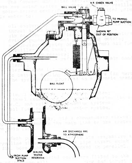
The action of the priming pump is from the float chamber of the water pump, through a float controlled valve and a non-return valve to the suction space of the port plate; the air discharge from the pump passes to atmosphere via the discharge space of the port plate and the sealing water reservoir filling overflow pipe.
The action of the priming pump is similar to that described for the ballast pump, but in this case the vacuum is automatically broken when the water pump is fully primed. This is achieved by the float operated valve, which, when shutting off the suction from the float chamber, opens a ball valve, which puts the pump suction to atmosphere via the sealing water reservoir (Fig. 13.)
A water seal is maintained between the water and priming pumps by means of rotary type packing. This packing consists of a bronze ring keyed to the impeller boss, bearing on a fixed carbon ring in the pump housing, contact being maintained by means of a spring. A synthetic rubber ring forms a water seal between the bronze ring and the impeller boss. The carbon ring is a push fit in the pump housing and is set with Halite. Similar type packing forms the priming pump gland.
4-27
4.11 OILY BILGE PUMP (CONTD)
(Figure 13)
Float chamber
A fine mesh copper cartridge strainer is provided in the water pump suction; it is recommended that this strainer be cleaned after each use of the pump.
4-28
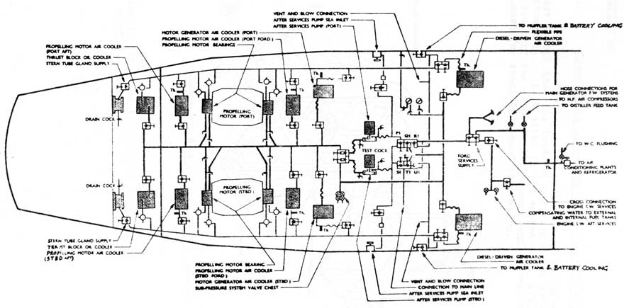
4.12 INTRODUCTION TO FORWARD AND AFTER SERVICES
The forward and after services each form part of a separate sea water system complete with two resiliently mounted motor-driven centrifugal pumps, provided primarily to supply water to:
oil coolers of the propelling motor bearings and thrust block bearings;
air coolers of the diesel driven generators, motor driven generators and propelling motors;
sub-pressure system of the external oil fuel tanks; distiller feed tank;
H.P. air compressors;
condensers of the refrigerator and air conditioning plants;
stern glands (if required).
to battery cooling heat exchangers (in harbour)
The system also provides an alternate means of
supply to:
diesel generators sea water system;
diesel generators fresh water system (in emergency);
W.C. and soil pipe flushing systems;
oil fuel compensating water system.
In an emergency, via a change-over six-valve chest, the pumps may be used on the main line or the system supplied from the main line.
Each pump is connected to its respective suction end discharge line through a flexible pipe insert which consists of six 2 in. bore rubber pipes arranged in parallel.
Four-way L ported cocks are fitted to the water outlets of the propelling motor bearing and thrust block oil coolers, in order to
(a) test to bilge, flow through inlet pipe to cock;
(b) test to bilge, flow through outlet pipe from cock;
(c) allow full flow through the line;
(d) shut off flow through the line.
A pressure gauge calibrated 0-400 lb/sq.in. and a differential gauge calibrated 50-0-50 lb/sq.in. are provided, and a pressure of 20 lb/sq.in. registered on the latter gauge is normally maintained.
4-29
(Figure 14)
FORWARD AND AFTER SERVICES
4-30
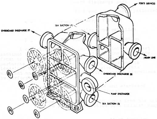
4.13 CHANGE-OVER SIX-VALVE CHEST (FORWARD AND AFTER SERVICES)
This chest is similar to the main line six-valve chest except that its internal partitions are arranged differently. It is sited In the engine room, aft, immediately in front of the after services pumps and is resiliently mounted for shock and sound insulation.
(Figure 15) Change-over 6-valve chest, F. & A. Services
Each valve spindle gland is packed with tallowed cotton and is provided with one inner and one outer 'O' ring.
4-31
4.13 CHANGE-OVER SIX-VALVE CHEST (FORWARD AND AFTER SERVICES) (CONTD)
The valve handwheels carry nameplates, thus:
NAMEPLATE
FUNCTIONS
U 1
Overboard discharge starboard
R 1
Overboard discharge port
T 1
M.L. to F and A services (padlocked shut)
Q 1
Pump discharge forward
S 1
Pump suction from main line
P 1
Sea suction cross-connection
A central transverse partition within the chest is machined to form orifices and seats for the six valves. In front of the partition the chest is divided into four compartments, while behind the partition the space is divided into three compartments as illustrated. This arrangement enables any of the following pumping operations to be performed:
(a) cross-connecting both port and starboard suction lines and return lines;
(b) pumping by either or both pumps from the main line to perform the duties of a ballast pump;
(c) forward and after services to be supplied from the main line.
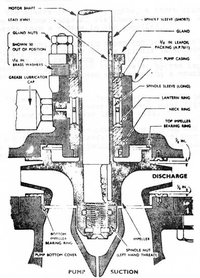
4.14 FORWARD AND AFTER SERVICES' PUMP (DRYSDALE TYPE 5 in.)
The Drysdale Type 5 in. pump is a motor-driven, single stage, vertically mounted centrifugal pump, with an output of 22,000 gal/hour at 2,860 rev min against a total head of 79 feet.
The assembly of the rotating element of the pump is shown in Fig. 16.
4-32
1.14 FORWARD AND AFTER SERVICES' PUMP (DRYSDALE TYPE 5 in.) (CONTD)
(Figure 16) FORWARD & AFTER SERVICES PUMP.
The pump spindle of stainless steel is integral with the motor shaft and is sleeved in stainless steel in way of the pump gland.
4-33
4.14 FORWARD AND AFTER SERVICES' PUMP (DRYSDALE TYPE 5 in.) (CONTD)
The sleeve is in two lengths, a short upper with a chamber on the inner edge of its lower face, and a long lower which extends into a recess in the impeller.
The impeller runs in upper and lower Cormin Alloy bearing rings, and is keyed to the spindle immediately below the sleeve' the key extending into the sleeve. It is retained on the spindle, together with the sleeve, by the impeller nut. The nut has a left hand thread and looked by a countersunk
screw.
Water is prevented from leaking upwards between the spindle and the sleeve by means of a lead joint fitted in the apace formed where the sleeve lengths butt.
The stuffing box contains a neck ring and three turns of 3/8 in. Alanite Leafoil packing on either side of a lantern ring, the latter being grease fed by a plunger type lubricator.
4-34
Large Plate on Separate Page
MAIN LINE:- ONONDAGA and OKANAGAN, and
MAIN LINE:- OJIBWA Fig 17