C.F. 'O' Class Submarines - Operations Equipment, describes the fire control and other operations of the Oberon class submarines.
In this online version of the manual we have attempted to keep the flavor of the original layout while taking advantage of the Web's universal accessibility. Different browsers and fonts will cause the text to move, but the text will remain roughly where it is in the original manual. In addition to errors we have attempted to preserve from the original, this text was captured by a combination of optical character recognition and human typist. Each method creates errors that are compounded while encoding for the Web. Please report any typos, or particularly annoying layout issues with the Mail Feedback Form for correction.
The submarine is a complex, offensive weapon which can be employed in a wide variety of roles. Amongst these roles are:
a. Anti shipping patrol
b. Anti submarine patrol
c. Intelligence gathering
d. Mine laying
e. Landing or picking up agents
To effectively carry out these tasks, the "O" class submarine is fitted with a wide variety of operations equipment. This notebook contains a brief description of this equipment and how it is used. For more detailed Information, consult the various books of reference held onboard on the particular piece of equipment you are studying.
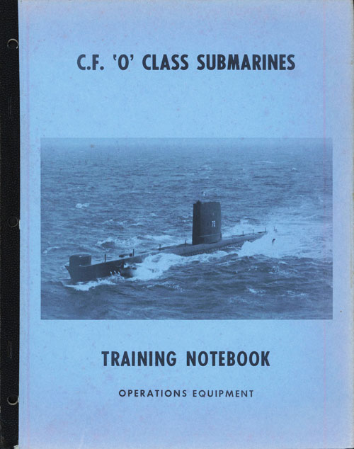
14.02 THE ATTACK TEAM
Every man onboard has an action station and is vital to the overall efficiency and success of the attack. The Attack Team are those members of the ships company who are directly involved in assisting the Commanding Officer to produce an answer in a given tactical situation. They are employed in the Control Room at Action Stations and are generally employed as in fig. 14.1. There may be some differences in your submarine, but the variations will probably only be slight.
When at Action Stations, no one should move throughout the boat. This makes unnecessary noise and could effect the trim.
14-2
14-3
14.03 SONAR EQUIPMENT
A. Noise is the prime source of information to the submarine. To gather and analyze this information, the submarine is fitted with several sonar sets, each designed to fulfill a designed purpose. The requirements are:
(1) An accurate, passive, medium range attack sonar
(2) An active, mine detecting sonar
(3) A passive, scanning torpedo warning sonar
(4) A passive, long range search sonar
(5) A sonar intercept sonar
(6) A reliable underwater communications set
(7) A self noise monitoring set
B. Submarine sonar sets are affected by the following:
(1) Sound velocity structure and the best listening depth
(2) Ambient noise level
(3) Self noise level
(4) Target radiated noise intensity
C. Sonar Sets Capabilities and Limitations
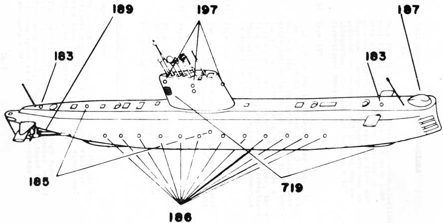
The locations of the various transducers and hydrophones is shown on the attached drawing (figure 14.2).
(1) Searcher
The type 186 is a long range passive sonar. It consists of 48 hydrophones, mounted in high and low frequency pairs either side of the submarine. The line array of the hydrophones suffer less attenuation loss than the directional transducers of other sets, which operate on higher basic frequencies. To operate the set, the submarine reduces to the maximum self quiet state (Ultra Quiet State) and swings in
14-4
C. Sonar Sets Capabilities and Limitations
(1) Searcher (Cont'd)
either direction at the best listening depth. The rate of swing varies but is usually recommended at between 16 and 20 degrees per minute.
The operator's console has a pen recording display which is activated by a noise on the beam bearing of the submarine, and produces a deflection trace from a normal. Bearing accuracy is obtained by a "cut on" "cut off" principle utilizing the whole array for reception.
(2) Type 187
The type 187 is a medium range search sonar and is also the submarines attack sonar. At the low frequency of 2.5 kc/s it has an active capability of hand transmission or fixed intervals of one and two thousand yards. The limitations of this set are:
(i) Susceptible to high self noise
(ii) Poor stern arc coverage
(iii) Loss of detection when firing torpedoes (this has been reduced with "swim out" torpedoes)
The operator has target center indication from "phones diff" relays and a deflection meter. Deflection meter contact is usually gained first and subsequent audio contact will be from low frequency or sonic channels. Good use of the set will produce a bearing accuracy:
L.F.
±1°
H.F.
± 1/4° (in practice ±1/2 °)
14-5
C. Sonar Sets Capabilities and Limitations
(2) Type 187 (Cont'd)
The sensitivity of the set falls off at very low frequencies but can be maintained constantly down to about 200 cycles.
In the active mode, ranges of out to 7000' can be obtained; one transmission may sometimes be used to check target range prior to firing.
(3) Type 719
The type 719 is a short range passing sonar whose primary function is torpedo warning and screen penetration. A high scan rate 12 RPM is useful for continual close target information. Two display are fitted a PPI display in the soundroom and a remoted linear bearing paper recorder.
Having two hydrophones, the stern arc is constantly swept; the normal form of operation is that the hydrophones sweep in unison cutting in/out on the beam.
The sets limitations are:
(i) The set has a low detection range
due to its high operating frequency.
(ii) Very susceptible to self noise,
particularly when snorkelling.
(iii) Sonar transmission blank out a lot of the detection capability, particularly long pulse transmission.
(iv) Poor bearing accuracy, ± 2° at long ranges decreasing as target intensity increases.
Type 719 can be integrated with type 187 and operated at 12.5, 15.25 or 17.75 kc/s as required. The advantage of this method is to increase bearing accuracy and discrimination. The 187 transducer is linked to the 719 display in this integration.
NARROW BEAM BY INTEGRATION WITH TYPE 187 (RANGE (6))
(a) 7,000x (b) 11,000x
186
SEARCHER
LONG RANGE SEARCH
SUBMARINE REQUIRES MAXIMUM SELF QUIET
60 MILES
187
ATTACKER
MEDIUM RANGE SEARCH ATTACK SET ACTIVE MODE
(1) USED FOR MINE DETECTION (2) USE TRANSDUCER WITH 185
22,000x
189
MONITOR
SELF NOISE MONITOR
LOCATED BY PROPELLERS (HAS PORTABLE SET)
-
197
WATCHER
SONAR (SURFACE) INTERCEPT
HAS BEARING INDICATOR AND FREQUENCY ANALYSER
-
719
SCANNER
TORPEDO WARNING SCREEN PENETRATION
VIDEO PRESENTATION AND C.R. DISPLAY
6-8000x
14-7
"O"CLASS
Location of Sonar Transducers & Hydrophones
14-8
C. Sonar Sets Capabilities and Limitations
(4) Type 185
Type 185 is the main underwater communication set; it has 3 transducers each with 1200 beam width, one mounted on the casing looking upward, and one each in Port and Starboard tanks. The transducers can be switched as required and the set can be integrated with type 187 to give a 12° directional beam.
(5) Type 197
Type 197 is the intercept sonar set. It has a frequency coverage from 3 - 40 Ws and the set is designed to analyze active sonar transmissions and give a visual bearing of the source. This bearing has a limited accuracy. As with all sonar, there is a best listening depth for interceptions; this will frequently expose the submarine to detection risk.
(6) Type 189
The self noise monitor hydrophone is used by the OOW to ensure the submarine is not cavitating.
(7) Type 183
Type 183 is the emergency underwater telephone, used only for submarine disasters. It is battery operated and has a range of 1000 yards.
14.04 SONAR ASSOCIATED EQUIPMENT
A. Tape Recorder
To assist the Sonar Operator with the classification problem, a three speed Phillips Tape Recorder is provided. It's electrical supply is 60 cycle 115V.
The operator records an HE at high speed, from all sets (particularly attacker in all frequency modes). The tape is played back at slow speed to allow a more accurate evaluation of:
14-9
(1) Number of propellers
(2) Blade rate
(3) Type of propulsion (diesel, reciprocating, turbine)
(4) Rev count
(5) In/out effect
B. Bathythermographs
Two U.S.N. type AN/BQN 1B bathys are fitted in the submarines. One sensing element is located in the keel and the other on the top of the fin. This bathy is a velocimeter. It actually measures the velocity of sound in the water around the sensing element.
This information is used in deciding the best listening depth or best evasion depth of the submarine. It also indicates to the trimming OOW if he can expect to be heavy or light as he changes depth due to the change in water density outside the submarine.
14.05 COMMUNICATIONS
Equipment Used by Submarines
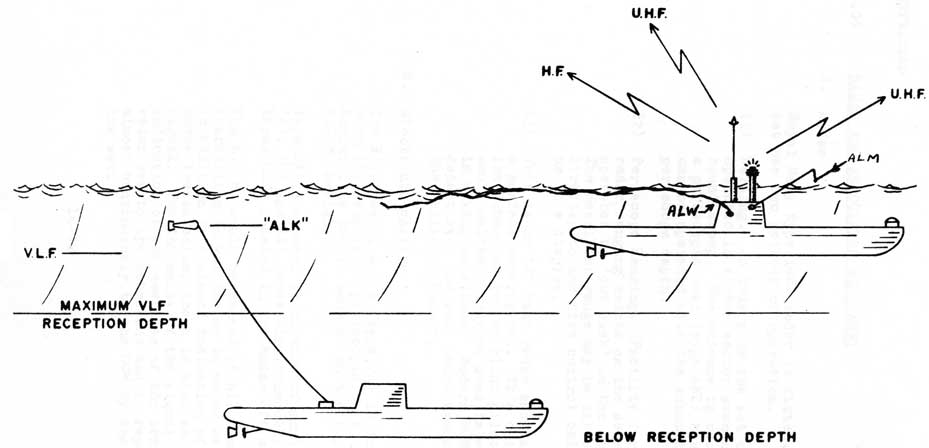
A. On the surface the submarine will use HF and UHF communications as would a surface ship.
B. Underwater, VLF broadcasts can be received at periscope depth and occasionally at greater depths by use of the 'ALK' buoy which increases the reception depth. When at periscope depth the submarine has HF and UHF facilities using the ALN mast and UHF facilities on the ECM mast.
Communications are possible at almost any depth with surface units and other submarines using the underwater telephone. This method is a very low security means of communication.
C. Submarine Broadcasts
Briefly, the system used for broadcasts of this nature is that the Operation Commander screens traffic for the submarine to determine which messages shall be transmitted. He will further decide if any of the messages have to be acknowledged and also how many times a message shall be run on the taped broadcast.
14-10
C. Submarine Broadcasts (Cont' d)
There is always uncertainty as to whether a submarine will receive a particular message, and this must be remembered when controlling a broadcast. Provisions do exist to place a message on an "essential" traffic list, and this would force the submarine to ask for the message if she had missed it on the broadcast runs.
The broadcasts are run at high speed (100 words/ min) and received in the submarine on a tape. This greatly reduces the submarines time at reception depth, or with the ALK buoy streamed.
D. The following equipment is fitted:
EQUIPMENT
QUAN
USE
AN/URC 32
1
Main HF transmitter
AN/ARC 94/618T
2
HF transceiver
AN/ARC 552
2
UHF transceiver
AN/URR 502A
2
HF receiver
CFA
1
VLF receiver
ANTENNA TYPE
PURPOSE
ALK
VLF aerial installed in recoverable buoy.
ALM
Omni directional VLF aerial comprising a series of loops in the fin.
ALN
Telescopic HF/UHF mast
ALW
Buoyant, disposable VLF wire aerial
AMK
UHF/IFF combined antenna associated with the ECM mast.
AWJ
Emergency whip aerial for use on the surface only.
See Fig. l4.3
The radio room has fitted a three speed Phillips Tape Recorder similar to the one in the sound room. This is used to record the high speed broadcast, thereby reducing the time at periscope depth or with the ALK streamed.
14-11
Antennas used dived near the surface.
Figure 14.3
14-12
14.06 RADAR AND ASSOCIATED EQUIPMENT
A. Radar
Royal Navy type 1002 radar is fitted. This set has two methods of operation.
(1) Warning. In this mode the set can be operated in either sector scan or an all round sweep. The antenna is mounted on a periscopic mast (type AKT) hence radar can be operated with the submarine at periscope depth.
(2) Periscope Ranging. Facility for direct radar ranging exists on the search periscope operated by 'cut push' on the periscope. The resultant range may be either fed directly to the fire control calculator or to a display.
(3) This is an "X" band radar and is chiefly a surface warning set. It's chief use in the submarine is for blind pilotage. It would unlikely ever be used in wartime or in making an attack. Modern ECM sets can detect even the very short transmission of the Periscope Ranger.
B. Electronic Warfare
The Royal Naval E.C.M. type UA4 is installed with its associated periscopic mast (type AYG). Aerial type AMK is mounted on the top of the E.C.M. aerial.
Type UA4 equipment is capable of monitoring 'X', 'C' and equipment bands simultaneously from three CRTs located in the Radar Office.
The E.C.M. would be manned at all times when snorkelling in wartime or in major exercises. In addition to a visual indication of an enemy transmission, there is also an audio signal. The intensity of the signal is an indication of the nearness of the transmitting radar set to the submarine and is reported almost continuously to the OOW by the RP on the set.
14-13
C. IFF
The IFF equipment fitted is the Royal Navy's type 955. The transponder only is currently installed.
This equipment enables an aircraft or ship to challenge the submarine with IFF. If the correct codes are set in the challenging ship and the submarine, the E.C.M. mast is raised and the IFF in the submarine is switched on, the transponder fitted will automatically send back the correct answer to the challenge from the ship or aircraft.
D. The Electromagnetic Log
This log is designed to detect and display:
(1) Speed - 0-40 kts indicating in 1/10 kt max error should be ± 1/4 kt
(2) Distance - displayed in control room in 1/10 mile.
There are three log sending elements fitted; two attached to 4 MBT port and stbd and one on the port side of the fin at bridge level. These probes may be changed without docking, but the log must be re-calibrated if they are. Only one probe is used at a time.
The amplifiers are fitted in the radar room. The display units are fitted above the chart table.
The buttons on the sensing elements require cleaning at regular intervals. They should be examined monthly by the divers doing engineering routines on the stern glands etc. and gently cleaned by rubbing with the bare fingers.
E. ARL Table
The submarine is fitted with one ARL table located in the stbd side of the control room. It is supplied with speed input from the EM log or a clock drive and with direction input from the ships MK 23 gyro. It is used for the following:
14-14
E. ARL Table (Cont'd)
(1) Dead reckoning navigation when dived
(2) Local operation plot at action stations
(3) Anti collision plot at blind pilotage
(4) Navigators work bench (stowage is provided beneath the plot for charts and nay. pubs.)
F. Semi Automatic Time Bearing Plot
This plot is mounted vertically at the forward end of the chart table. It is made of clear plexiglass graduated horizontally and vertically. The vertical graduations cover an arc of bearing; the horizontal graduations cover a time scale selected by the Sonar Control Officer. A moving guide is driven up the plot at a rate (3"/min or 1"/min) to guide the back plotter in placing his target plot on the time scale. This is to increase the accuracy of the plot.
The time base is taken from the clock fitted in the ARL table.
This slot is normally only manned at Action Stations.
G. The Contact Evaluation Plot C.E.P.
This plot is mounted in the control room in a convenient spot. It is basically a time/bearing plot like the semi anti plot, but on a much smaller scale. It is manned at all times at sea and is used to record all contacts and other significant information. It is used by the OOW to determine rough courses of contacts and by the CO to evaluate the tactical situation. Accuracy and thorough, neat recording are of paramount importance.
H. MK 23 Gyro
The submarine is fitted with two MK 23 gyro compasses. There are no other compasses fitted. They supply course information for the following:
14-15
H. MK 23 Gyro (Cont'd)
(1) OMC to steer by
(2) ARL table for DR navigation
(3) TCC for fire control solutions
(4) Sonar sets for gyro stabilization
(5) MK 37 torpedo director
(6) Radar and ECM for gyro stabilization
(7) Periscope read-off for gyro bearings
Advantages over previous gyros are:
(1) Much smaller and more compact
(2) Fast settling mode
(3) Accurate to 750 latitude and used higher if need be
These gyros are fitted in the gyro room, in the after end of the A.C.S.
14.07 NAVAIDS
It is essential in both wartime and peacetime for a submarine to know it's accurate position. To this end, several pieces of equipment are fitted.
A. Loran
Loran is a radio fixing aid. It receives signals from shore stations and by adjusting the received patterns of signals, a reading for each station is obtained. This reading may then be plotted on a special Loran Chart.
It is located at the after end of the chart table in Onondaga and Okanagan. In Ojibwa it is located in the radar office.
Loran may be used on the surface or dived. It uses the HF section of the Communications mast for an aerial. It is always patched to the aerial. Loran is a long range aid, covering most portions of the Atlantic Ocean.
B. Decca
Decca is a radio fixing aid. It operates in a similar manner to Loran and has its own special Decca charts for plotting.
14-16
B. Decca (Cont'd)
It is located above the chart table. It may be used on the surface or dived. It uses the UHF section of the communications mast or the UHF section of the ECM mast. The changeover is completed in the radio room. Decca is a relatively short range aid, but is highly accurate. Decca coverage is coastal only.
C. Consul
Consul is a radio fixing aid. It is a system of dots and dashes transmitted by shore stations and received by the normal communications receivers and masts. It may be used surfaced or dived. It is a long range aid, but is very inaccurate. The results obtained are plotted on special Consul Charts. Admiralty Lists of Radio Signals give details of frequencies for the Consul Stations. Consul is seldom used.
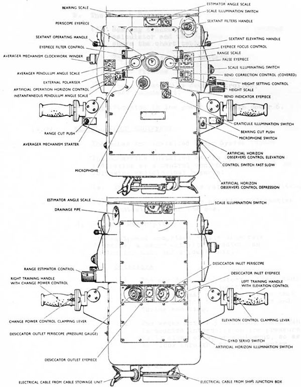
D. Artificial Horizon Sextant
This sextant is fitted in the attack periscope. It is used to take astronomical observations of the sun, moon, planets and the brighter stars.
The advantages of this sextant over previous sextants are:
(1) The submarine may remain dived to take an astronomical fix.
(2) Star sights may be taken at anytime of the night and not just at dawn or dusk.
(3) Accurate sights may be taken, regardless of the clearness of the horizon.
Some disadvantages are:
(1) The periscope must be up for a minimum of two minutes for each observation.
(2) At least three feet of the attack periscope must be shown to have the sextant window clear of the water.
14-17
D. Artificial Horizon Sextant (Cont'd)
(3) Errors will be introduced by heel and trim angles and can be calculated for only by estimations of the average heel and trim angles over the period of the sight.
The sextant has three power supplies:
(i) 220V DC
(ii) 24V DC
(iii) 110V 400 cycles
This sextant is a great advance in submarine navigation equipment. It may also be used as a natural horizon sextant.
E. Echo Sounders
The type 773 & 776 echo sounder is installed in
the submarines. It's transducer is fitted
fwd at keg]. level and it's display units,
shallow and deep, are fitted in the control
room, aft of the chart table. The control
panel is fitted alongside the display unit.
It gives good results down to depths in excess
of 1000 fathoms. This is a great aid when used
in conjunction with other fixing aids and
special bottom contour charts. It's chief
disadvantage is that it is an active aid
requiring a transmission from the submarine.
(No one may make a transmission from the
submarine at sea without the Commanding Officers'
approval).
F. Other Aids
Other aids, previously mentioned, are:
(1) EM log and recorders
(2) ARL Table
(3) MK 23 gyros and repeaters
14.08 PERISCOPES
Two types of periscope are fitted into the "0" class submarine.
14-18
A. The Attack Periscope
This is a type CH74, monocular periscope.
The size of the tube at the top is 2 inches
in diameter. This makes the attack periscope difficult to detect, either by eye or by radar. The length of the attack periscope is 44 ft.
9 in. four feet longer than the search periscope. This enables the submarine to be slightly deeper when attacking, a tactical advantage in case of
aircraft and enables the submarine to save previous seconds if forced to go deep by an escort.
It is fitted with the following:
(1) Artificial horizon sextant
(2) Action broadcast microphone
(3) Split image range finder
(4) Range transmission to the fire control calculator
(5) Bearing transmission to the fire control calculator and the bearing indicator above the chart table
(6) Top window de-icing heaters.
The magnification in low power is 1.5 and high power is 6.
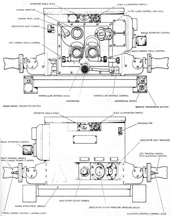
B. The Search Periscope
This is a type CK 24, binocular periscope. The size of the tube at the top is 7.5 inches in diameter. This makes this periscope a good visual and a good radar target. The length of the search periscope is 40 ft. 9 in.
It is fitted with the following:
(1) Ranging radar - very short transmission
(2) Action broadcast microphone
(3) Split image range finder
(4) Camera aperature
14-19
SEARCH PERISCOPE-FACEPLATE CONTROLS AND BOTTOM OUTER CASTING
Figure 14.4
14-20
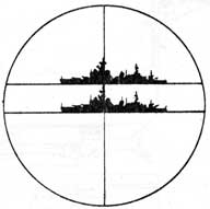
14.08(A) RANGE ESTIMATOR
To estimate the range of a target:
(1) Switch on the scale illuminating lamps, if necessary.
(2) Rotate the estimator control to 'IN' then pull it fully outwards.
(3) Rotate the right handgrip to the high-power
position.
FIELD OF VIEW SHOWING RANGE ESTIMATOR IN USE
(4) Rotate the estimator control until the bottom of that part of the ghost image whose height is known is exactly superimposed on the top of the corresponding part of the main image; that is, the ghost image should be moved through a distance equal to its apparent height.
(5) Note the range displayed on the estimator range scale.
NOTE: When using the periscope for normal observation the operator should first check that the estimator prisms are swung out of the beam, lest definition is adversely affected. This is done by rotating the estimator control so that the scale reads zero, then pushing fully inwards and rotating to 'OUT'.
14-21
ATTACK PERISCOPE-FACEPLATE CONTROLS AND BOTTOM OUTER CASTING
Figure 14.5
14-22
B. The Search Periscope (Cont'd)
(5) Bearing transmission to the fire control calculator end the bearing indicator above the chart table.
(6) Top window de-icing heaters.
(7) Light filters
(8) Power rotation by foot controlled, seat roundabout.
Magnification in low power 1.5, high power 6.
14.09 MISCELLANEOUS EQUIPMENT
A. The Submarine Installed Radar System (SIRS)
The Submarine Installed Radiac System provides indication at a central control position of the following radiological hazards:
(a) The external air dose rate of gamma radiation.
(b) The presence of gamma emitting radioactive contamination in the sea.
B. General Description
The equipment comprises en air dose rate detector, a water activity detector, an indicating unit and a power unit.
(a) Detectors
(i) The air dose rate detector (Mark 8NH)
is mounted in the junction box for the snort head valve heaters so that it can monitor the air prior to and during snorting.
(ii) The water activity detector (Mark 9NH) is mounted internally on the pressure hull, clear of other equipment, so as to "look through" at the sea water.
14-23
B. General Description (Cont'd)
(b) Indicating Units
One display unit (Mark 4NV) is fitted at the central control position and contains the meters which provide measurement of the level of radiation in the air and water around the submarine. The information provided is as follows:
Air Dose Rate meter range 10-4 - 50 rad./hr.
Water Activity meter range 0.75 x 10⁻³ - 0.75 uC/cc
A visible and audible warning is given at this position of both the Air Dose rate and the Water Activity when the activity rises above the pre-determined levels. These levels may be pre-set between the following limits:
A.D.R. 3 x 10⁻⁴ - 10-2 rad./hr.
W.A. over the equivalent range.
The audible warning can be silenced by
depression of the 'mute' switch. A 'reset' switch is provided to reset the alarms. Magnetic indicators show when each channel is:
(i) On.
(ii) Off or Failed
(iii) Has a high reading. This alarm indication can only be reset when the level falls below the pre-set level.
(c) Amplifier/Power Unit
A cubicle (Mark 132AA) containing two power units (Mark 10NP), two ratemeter and alarm units (Mark 5NA) and a test unit (Mark 1NTU) is supplied with either 115 volts, 1 phase, 60 c/s or 230 volts, 1 phase, 50 c/s.
14-24
RADIAC SYSTEM MK. 3. N.R.S.
TYPICAL INSTALLATION IN CONVENTIONAL SUBMARINE
Figure 14.6
14-25
B. General Description (Cont'd)
(c) Amplifier/Power Unit (Cont'd)
The various power supplies required by the system are derived from the power unit with the exception of the 24 volts d.c. supply required for the audible alarms which is obtained from the submarine's 24 volt supplies. The second power unit is a spare.
The ratemeter and alarm units are identical for the two channels. The test unit
enables the ratemeter and alarm units to be set up and checked and the power supply voltages to be monitored.
14.10 SUBMARINE FIRE CONTROL
A. Basic Principles
The initial purpose of a Submarine Fire Control System is to resolve the track on which the torpedo must travel in order to intercept the target. This track can be considered as a lead angle from the target bearing on firing, and is therefore influenced by both target movement and own motion.
Another function, no less important, of the
system is to relay weapon settings of depth, speed, track and pattern of run from the Control Room to the individual torpedoes.
The final function is to pass command signals to a wire guided torpedo after discharge.
B. The Fire Control Problem
As with any guidance and direction system, the aim is to place a weapon, or pattern of weapons, on a given target. The variables affecting submarine fire control problems are:
(1) Target range and relative speed across the line of sight
(2) Own speed across the ling of sight
(3) Weapons characteristics
14-26
B. The Fire Control Problem (Cont'd)
With these known variables, the fire control calculator or computer will produce and transmit headings on which the torpedoes must travel in order to intercept the target.
C. Fire Control Computer
The computation that has to be made by the fire control system is to determine the torpedo track required. Own and target data is continuously updated either manually or automatically from sensors.
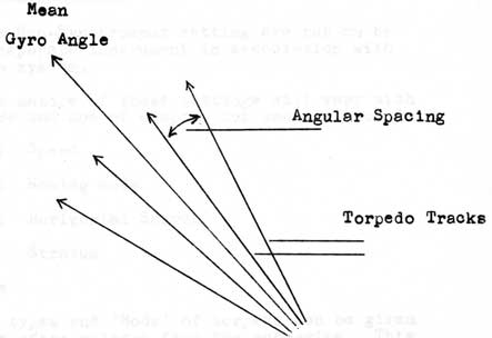
This track is then related to own ships head to give a precision gyro angle to the weapon. In the case of a multiple weapon firing, this angle becomes a mean angle and is converted to the linear spread; each torpedo then receiving different track. Adjustments can be received by the torpedo up to the moment of individual release.
14-27
C. Fire Control Computer (Cont'd)
In addition to solving the gyro angle for a particular target set up, the computer can track a target on a given course, speed and range and is able to receive updating ranges and bearings.
D. Retransmission Component Parts
Previous mention was made to the ability of the system to transmit torpedo settings to the weapon. Much depends upon the type of weapon as to what settings are required. These fall into two catagories:
(1) Synchronous
The Synchronous settings are those set from the computer and are:
(a) Gyro Angle (torpedo track)
(b) Enabling distance
(c) Depth
(2) Non-Synchronous
The Non-Synchronous settings are put on by a separate instrument in association with the system.
The nature of these settings will vary with type and mod of weapon, but usually include:
(a) Speed
(b) Homing mode
(c) Horizontal Search
(d) Stratum
E. Guidance
Certain types and 'Mods' of torpedo can be given guidance after release from the submarine. This is made possible by maintaining continuity between the fire control system and the weapon by a light single core wire. Commands to the weapon are given in azimuth and depth from the submarine where a D.R. track of the course and speed of the torpedo is maintained.
14-28
F. CONCLUSION
At present the RCN 'O' class submarine is matched to the USN MK 37 torpedo; this weapon has two mods; Mod 0 and Mod 1. The Mod 0 is an active/passive homing torpedo and Mod 1 a wire guided/homing torpedo.
Further developments in submarine weapons are followed, and in particular new 'Mods' to the MK 37 torpedo which it is anticipated will be considered for RCN submarines.
G. System Components
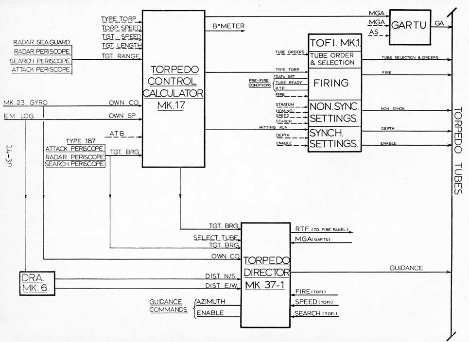
(1) Calculator - located in the control room
Inputs
(a) Own speed (log)
(b) Own course (gyro)
(c) Torpedo characteristics (set by hand)
(d) Enemy co, speed, and range estimations (set by hand)
Output
Mean Gyro Angle (MGA)
(2) Gartu - located in the control room (gyro angle retransmission unit)
This accepts the MGA from the calculator and spreads the salvo about it. Some of the torpedoes in the salvo will travel to the right and some to the left of the MGA for greater target coverage.
(3) TOFI - located in the control room (Torpedo Order Fire Instrument)
This instrument is used to relay order to the forward or/and after torpedo rooms ordering the tube to the required state of readiness. The synchronous and non synchronous settings are also set on the torpedo from the TOFI. Indicator lights burn when the required settings are accepted by the torpedo (DATA SET) and when the tube is ready to fire. Finally, the torpedo is fired from the TOFI.
14-29
G. System Components (Cont'd)
(4) MK 37 Director - located in the Control Room.
This instrument is used to guide the MK 37 mod 1 and mod 2 torpedoes after they have been fired. It has a gyro fed from the MK 23 Gyros and an indication of HE bearing from the attack sonar set. The operator keeps two pointers aligned; one represents the torpedo, the other represents the target. Then "BANG".