C.F. 'O' Class Submarines - Escape, describes the emergency escape procedures of the Oberon class submarines.
In this online version of the manual we have attempted to keep the flavor of the original layout while taking advantage of the Web's universal accessibility. Different browsers and fonts will cause the text to move, but the text will remain roughly where it is in the original manual. In addition to errors we have attempted to preserve from the original, this text was captured by a combination of optical character recognition and human typist. Each method creates errors that are compounded while encoding for the Web. Please report any typos, or particularly annoying layout issues with the Mail Feedback Form for correction.
As submarines have developed throughout the years, there has grown up with them a considerable technique devoted to the escape of men trapped in a sunken submarine and to the salving of the boats themselves.
A start was made in 1904 in working out methods of raising ships as they lay on the bottom, but the problem of saving men was one that for many years defied human ingenuity.
From the early submarine calamities, men escaped, or failed to escape, more or less according to the depth of water in which the submarine lay and to the degree of damage suffered by the submarine. if they were able to isolate the damaged compartment and equalize the pressure in the undamaged compartments with sea pressure by flooding, it was possible to open the hatch in that compartment and release the air, this rushing to the surface in a great bubble.
It was in those bubbles that the trapped men made their escape. Whether they lived or not depended on the depth of water in which the submarine was lying, for as moon as the air was compressed they were prone to the same disease as the diver "the bends", and also to a rising partial pressure of carbon dioxide, which, depending on the percentage present at the commencement of flooding, could be lethal.
Midway between the two wars the Davis Submarine Escape Apparatus (DSEA) was produced; using this equipment the escaper breathed pure oxygen and was much less prone to the "bonds" because the oxygen dissolved the nitrogen in his blood.
Obviously not all the men in the submarine would be able to escape in the bubble and a method was needed to enable all men to escape.
10-2
Two small escape chambers, which could be flooded separately, fitted in different compartments, provided the answer, one to four men were thus able to escape at a time, using DSEA.
Later methods saw the removal of the chambers and reverted to flooding the compartment again, the escapers however did not go out with the bubble but escaped through a nylon trunk which protruded from the escape hatch into the water in the compartment, neither did they breathe the air in the compartment whilst flooding but pure air carried in bottles. His chances of avoiding CO2 poisoning were thus greater, but he was still liable to the bends if he breathed this air under pressure for too long, and so the depth from which he could escape was limited.
Modern submarines use a one man escape chamber in which the escaper doesn't breathe air under pressure for more than a few seconds before escape and using this method escapes from a depth of 750 feet are possible.
10.01 PURPOSE
To save life at, the expense of the submarine. The salvage of a submarine to save life is not practicable and would take too long. Individual escape from the sunken submarine is now the accepted method of saving life.
10.02 MAIN FACTORS REQUIRED FOR SUCCESSFUL ESCAPE
A study of successful escapes has shown conclusively that two main factors are vital for success:
a. Knowledge of the principles of escape and details of the equipment.
b. Determination on the part of all escapers.
10.03 ESCAPE THEORY
If a submarine is sunk, unless it has been flooded throughout, one or other of the end compartment is the least likely to be flooded, and survivors should make their way to that compartment.
10-3
10.04 ESCAPE POLICY
To provide an unpolluted supply of air to all the crew, and
necessary escape equipment in each of the end compartments (FTR & ATR).
10.05 WHEN TO ESCAPE
Depends on the circumstances at the time. Wait until found by surface if possible. How long you wait will depend on condition of air and whether flooding or not. Start air purification immediately after the accident:
4 CO2 canisters every 2 hours (air or preferably electric)
1 O2 candle every 2 hours (not if CO2 unit in air drive)
Air purification can be regarded as running at FULL EFFICIENCY if one CO2 unit and O2 Generator is available for every 32 men. Anything else is regarded AS REDUCED EFFICIENCY.
A. If BIBS is Not Available
(1) Escape as soon as air purification can no longer be run at FULL EFFICIENCY
(2) If no air purification is available escape at once.
B. If BIBS is Available:
Take half hourly readings of percentage of CO2 and Absolute Pressure in atmospheres. Multiply these readings together, and you must start escaping when:
(1) Figure so obtained reached 4.5 or
(2) Comportment pressure (shown on Absolute Gauge) reaches 1.5 atmosphere.
WHICHEVER OCCURS FIRST
10-4
A man-hour table is available in the red cross lockers, which gives a rough forecast of time available before escaping. When surface ships locate a sunken submarine they will drop 12
grenades to let the survivors know they are ready to pick them up. Then escape without delay. If ship or ships appear to remain in vicinity, escape should not necessarily be delayed until the grenades are heard.
10.06 ESCAPE COMPARTMENTS
In 'O' Class submarines these are FTR and ATR. In Ojibwa only, the E.R. is a supplementary escape compartment and can be used in conjunction with the ATR should all the crew have to escape from aft. The FTR is big enough to handle all crew and a few passengers.
10.07 ESCAPE FITTINGS
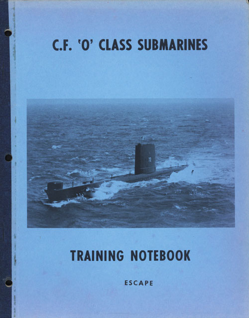
A. Nylon Trunk (Figure 1)
An open ended cylindrical trunk made of proofed
nylon, stretched over metal strengthening rings. Normally triced up under hatch. Top secured by a metal band and rubber joints to a skirt ring below the hatch to form an air tight joint.
Secured to deck by four 1" lines attached to opposite sides of trunk, through eyebolts in deck and secured to trunk. The bottom of the trunk is normally 3 1/2 ft. from the deck, but it Is
reefed up to black line when deeper than 150 ft.
B. Differential Pressure Gauge
One connection to sea, one to compartment,
graduates 30-0-150 PSI, indicates the depth, and enables a check to he kept on differential pressure during flooding up, especially when "Air Aiding".
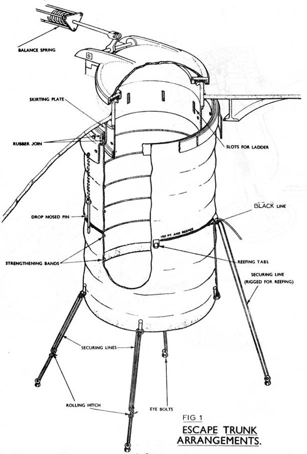
C. Flood Valves (Figure 2)
One 8" and one 6" in F.T.R.
Two 8" in E.R. in Ojibwa
One 6" in A.T.R.
Wire/lead sealed In "SHUT" position
D. Flap Valves (Figure 2)
One on each flood valve pipe inboard of valve. Can be shut if flood valves leaks or is damaged. Vice headed bolt is fitted between flap and
flood valve to relieve pressure above: flap valve so that it may be opened. Flap valves are
wire/lead sealed in "OPEN" position.
Two in each escape and supplementary escape compartments, sited near escape hatches. Contain 2 Long Breathing Units and Escape instructions. 2 Pressure Tight Flashlights and a wheel spanner. Also contains a vent cap on Onondaga and Okanagan.
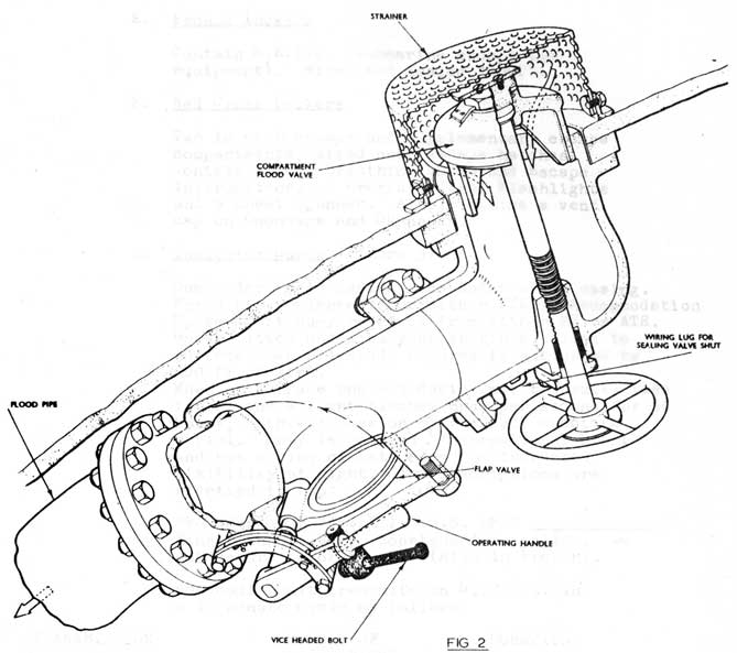
G. Indicator Buoys (Figure 3)
One under for'd casing, one under after casing. For'd buoy released from either FTR or Accommodation Space. Aft buoy released from either MR or ATR. Buoys fitted under buoyant gratings, float to surface when released, secured to submarine by 600 ft of wire.
When on surface the 609 Radio Unit transmits (see table) and a light flashes once per second for 60 hours, both switches on by the self erecting
aerial. Buoy is painted "International Orange"
and has a ring of cats eyes for increased visibility at night. Two inscriptions are rivetted to top:
"FORWARD" (or "AFTER") S.O.S. HMCS ______!
Finder inform Navy, coastguard or police. Do not secure to or touch. (Also in French).
609 Radio Unit transmits on 4178 Kcs. in a 10 minute cycle as follows:
TRANSMISSION
NUMBER OF REPETITIONS
DURATION
3 Fig. Serial No.
3 Times
30 Secs.
S.O.S.
6 Times
30 Secs.
Sub Sunk
3 Times
30 Secs.
Long Dash
Once
30 Secs.
Above is transmitted twice giving a total transmitting time of 4 minutes.
The transmitter is then silent for 6 minutes, and then the cycle begins again.
10-8
10-9
H. Pressure Tight Torches
Four in each escape and supplementary escape compartment in Red Cross lockers. Used as necessary if lighting fails.
I. B.U. Lookers.
Contain Breathing Units, sufficient for all crew plus a few passengers, in each escape compartment.
J. Underwater Telephone
Type 183 in each escape compartment.
Range: 1000 yds. max. (Sea State 3)
Life: 12 hours transmitting, 72 hours receiving.
Power: Self Contained Battery
Frequency: 8087 Ks.
(i) Speak slowly and clearly to prevent words being jumbled.
(ii) Wait for sound waves to reach surface and for reply to reach you. After calling, wait 15 seconds with S.R. switch to receive before switching to send and trying again.
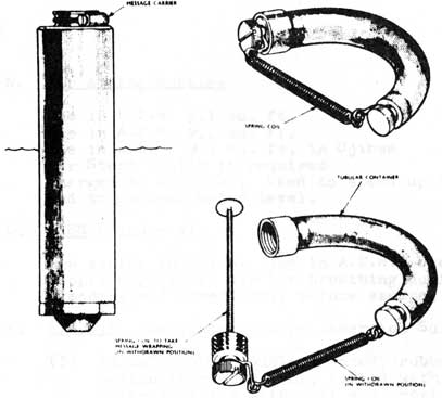
K. Submerged Signal Ejectors
One in each escape compartment.
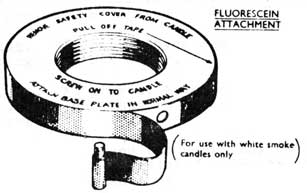
A special 625 foot type N5 white smoke candle is used to carry:
One of each in each escape compartment.
Primarily for preservation of the atmosphere during long dives, details in connection with escape contained in appropriate "WHEN TO ESCAPE" instruction cards. One extra O2 generator is fitted in 'O' Class submarines in the accommodation space.
M. Ringrose indicators and Budenberg Gauges.
One of each in each escape compartment. Ringrose
Indicator shows percentage of CO2 present in atmosphere. Budenberg Gauge shows absolute pressure in Atmospheres.
Reads 0 0.5 1.0 1.0 2.0
10-10
-
FIG 4 Details or Message carrier
FIG 5
10-11
N. Air Aiding Bottles
One in F.T.R. 9.1 cu. ft.
One in A.T.R. 9.1 cu. ft.
One in E.R. 9.1 Cu. ft. in Ojibwa
Air Start bottle if required
Charged to 4000 P.S.I. Used to speed up flooding and to control water level.
O. BIBS (Figure 7)
One system in F.T.R. One in A.T.R. Used to supply unpolluted air for breathing during flooding and immediately before escape.
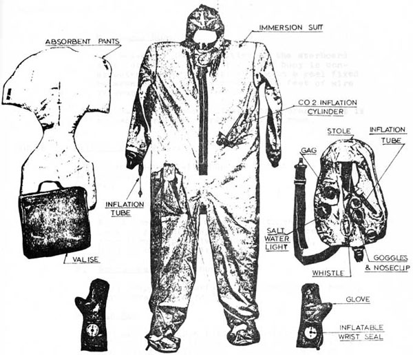
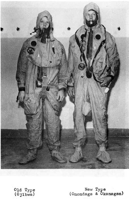
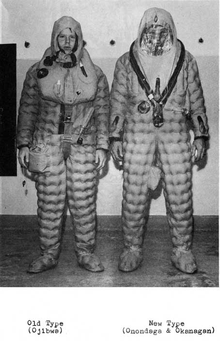
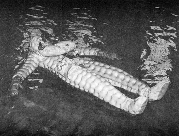
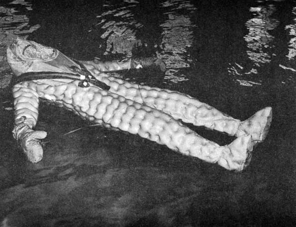
P. S.E.I.S. (Submarine Escape Immersion Suit) (Fig. 6)
(1) An inflatable double skinned, rubberized cotton fabric garment, fitted with hood which inflate with suit and provides thermal insulation. Hands protected by gloves with inflatable wrist seals. Inflated on arrival at the surface by a bottle of Compressed Carbon Dioxide carried on left hip. Subsequent inflation is by mouth via an inflation valve in right cuff (RED).
(2) Absorbent Pants. Cotton wool backed by P.V.C. secured around waist by tapes, worn next to skin, to absorb urine which would otherwise lie in small of back and reduce protection offered by S.E.I.S.
(3) Goggles. To protect eyes against oil, etc. floating on flood water.
(4) Noseclip. To prevent involuntary breathing through the nose and to assist in cleaning the ears.
(5) Stole. Worn around the neck, may be used with or without SEIS. Inflated by mouth or by putting over exhaust of demand valve. Inflation valve YELLOW. Has a relief valve to prevent bursting on way up when external pressure is decreasing, shut on surface. Fitted with a whistle and automatic light powered by a salt water battery at back of neck gives a white light for 36 hours.
N.B. Not carried in Onondaga or Okanagan with the new SEIS. (See photographs).
One messenger buoy is fitted on the starboard side forward in the casing. The buoy is constructed of two buoyant drums with a reel fixed between them. Approximately 1200 feet of wire is wound around this reel.
The buoy is painted international orange. it is released from the forward torpedo room.
10.08 METHODS OF ESCAPE
Compartment Escape with buoyant ascent
Rescue Bell
One Man
A. Compartment Escape
Flood compartment, equalize with sea, escaper uses no breathing apparatus during ascent, but some form of positive buoyancy (STOLE), or Hood on the new suits.
B. Rescue Bell (American)
Bell dropped by surface ship over escape hatch, survivors escape in bell.
C. One Man
FTR and ATR escape hatches converted to one man escape chamber, thus the whole compartment does not have to be flooded. One man escapes at a time, breathing from a hood all the way to the surface.
10.09 STEPS TO ESCAPE (COMPARTMENT ESCAPE)
A. Indicate Position
Release indicator buoys, fire pyrotechnics. Transmit on S.S.T. and U.W. telephone. Blow or pump out oil. Hammer on hull.
YELLOW Candles by day, to avoid confusion with smoke floats used by aircraft.
WHITE Candles by night as they emit flame.
10-14
B. Prepare to Flood
Remove all loose gear, take all pressure tight torches and AELs into Compartment.
(a) Seal the Compartment
(1) W.T. door
(2) BLKD vent valve and voice pipe cock
(3) Pipes going through bulkhead
(4) Tighten torpedo loading hatch
(5) Blanks in breech and vent and drain pipes of SSE.
(b) Prepare to Flood (Compartment)
(1) Isolate electrically
(2) Rig escape platform
(3) Escape hatch handle to "open" position
(4) Rig trunk, reefing if depth greater than 150 feet.
OPEN UP BIBS
(a) Check hull valve open
(b) Remove Diaphragm Valve Safety Collar
(c) Open Diaphragm valve slowly
(d) Open stop valves to one reducer, reading should be 100-130 PSI use other reducer if not.
(c) Prepare to Flood (Man)
(1) Dress in SEIE
(2) Issue breathing units (BU)
(3) Line up through compartment, plug in BIM to manifold, two long B.U. nearest trunk (test)
(4) On noseclip, insert mouthpiece, start breathing.
C. Flood Up
(1) Open Compartment Flood Valves
(2) If depth exceeds 250 feet release all air from air aiding bottle. Flood rapidly and continuously
(3) Inflate stole by plugging into BU outlet, vent air from SEIS. Check stole relief valve gag DOWN. Put on goggles.
10-15
D. Escape
(1) Man nearest trunk with long BU ducks under trunk, opens hatch, drops BU, makes buoyant ascent.
(2) Second man with long BU acts as despatcher by tapping each escaper when trunk is clear.
(3) Remainder keep closed up to trunk by using vacated BUs. Hold breath when exchanging BUs.
(4) When despatcher signals, take a deep breath from BU, drop BU, duck under trunk, make buoyant ascent.
BREATHING OUT, ALL THE WAY TO THE SURFACE
When on the surface, shut relief valve on stole, inflate SEIS, inflate stole, put on gloves interlacing with others to keep together. Lie still to conserve energy.
RUSH ESCAPE
As above, not waiting, no air purification, use S.E.I.S.
if time permits. This type of escape is made when flooding or gassing does not permit any delay. S.E.I.S. must be used in Onondaga and Okanagan as no stoles are carried.
10.10 RESCUE BELL - INTRODUCTION
The Rescue Bell is a method of escape primarily used in the USN. CAF submarines are fitted to employ this method.
A Rescue Bell escape could be made from a CAF 'O' class submarine under certain circumstances:
(1) The availability of a Submarine Rescue Ship (ASR)
(2) The exact position of the disabled submarine being known by the Rescue Force
(3) The survivors being able to delay their escape until the Rescue Bell arrives.
10-16
10.11 ACTION IN THE SUBMARINE AND DESCRIPTION
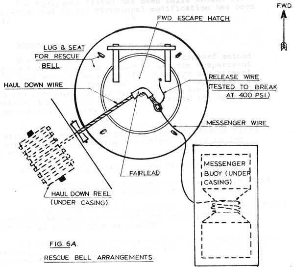
A disabled submarine indicates its position to the ASR vessel by releasing buoys which remain attached to the submarine by mooring wires. In the case of Rescue Bell operations a messenger buoy is also released and this consists of two buoyant drums joined together in a manner to form a 'waist' between them. Around this waist are 1200 feet of tight wire rope, secured at the one end to the buoy and at the other to a larger wire in the submarine's casing. This latter wire passes through a conduit on the escape hatch and is subsequently used as a 'haul down' for the Bell. (See Fig. 6A).
The buoy is located in a well in the fore casing of CAF 'O' class submarines and is kept in place by two buoyant covers; these covers in turn are retained in place by bolts that can be retracted from within the submarine.
In CAF 'O' class submarines, only one buoy is fitted and the associated hatch is the forward escape hatch. The after escape hatch is fitted to receive a Rescue Bell but has no buoy or haul down. A wire would have to be fitted to the hatch by divers to act as a down haul.
10.12 ACTION BY THE ASR AND DESCRIPTION
The first action by the ASR vessel is to recover the messenger buoy and haul up the free end of the second wire.
Once the recovery has been made the ASR moors itself over the sunken submarine and connects the haul down wire to the Rescue Bell. When full preparations have been made, the Bell is manned and it winches itself down to the submarine.
10.13 THE RECOVERY
Around the escape hatch on the submarine is a 12 inch steel rim; on this rim the Rescue Bell seats. This is a machined surface and must be well maintained.
The construction of the escape hatch is such that it may be opened from outside or within the submarine. When the Bell is correctly seated, the escape hatch is opened and the survivors enter the Bell, and so to the surface. More than one trip to the submarine may have to be made by the Bell.
10-17
10-18
10.14 ONE MAN ESCAPE - INTRODUCTION
One man escape chambers are fitted to SS 73 and 74; those currently fitted are of a Royal Navy design and utilize their method of operation.
The equipment fitted has been built around older escape systems and little structural modification has been required.
10.15 GENERAL
For a large number of years the standard method of escaping from a disabled submarine was the compartment type. In this method the whole of the escape compartment had to be flooded until the pressure in the compartment was equal to sea pressure, the escape hatch was then opened and survivors took a deep breath and ascended to the surface, breathing out all the way.
It will be seen that the survivors commenced to breath air under pressure as soon as the compartment flood valves were opened thus making themselves liable to the adverse effects of:
(a) Breathing excess Carbon Dioxide, and
(b) Breathing nitrogen under pressure which could cause nitrogen narcosis or the Bends.
The flooding of the compartment was therefore carried out as rapidly as possible so that air under pressure was breathed for as little time as possible.
By converting the escape hatches into escape towers or chambers, a great reduction in the time air was breathed under pressure was made possible.
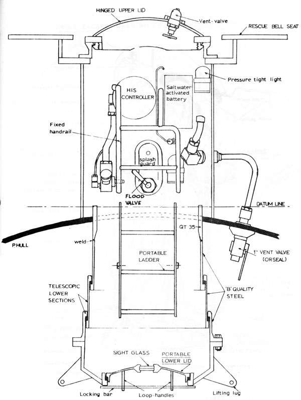
10.16 A BRIEF DESCRIPTION
The single escape towers consist of cylindrical steel tubes protruding through and welded to the pressure hull, fitted with a hatch at the top and bottom. The top, or external hatch can be opened by the escaper from inside the tower by hand, or, it can be opened or shut, using a portable handwheel, by the personnel remaining in the compartment.
10-19a
Plate 1
10-19b
Plate 2 AFTER ESCAPE TOWER
10-19c
Plate 3
10-20
The lower hatch is portable and slightly oval in shape so that it will pass through the opening. it is secured by a locking bar inserted through the handle loops.
The tower is flooded through a 1" flood valve which is normally operated from inside the submarine, but it can be opened or shut from inside the tower by the last man to escape.
The 1" orseal vent valve and the 1 1/2" orseal drain valve can be operated only from inside the submarine, the last man taking a cap for the vent pipe into the tower with him.
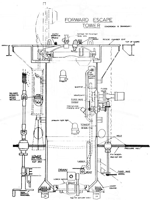
10.17 FORWARD ESCAPE TOWER
The forward escape tower is fitted between frames 24 - 25 in the F.T.R. The tower or external section, is made of 'B' quality mild steel and is welded directly to the lower section of QT 35 which is welded into a pressure hull pad of 1.08" thick QT 28. The seating for the rescue bell, made of B quality steel, is welded to the top of the tower. The tower is strengthened by 3" x 3" circumferential stiffeners. The internal diameter of the tower is 29" and of the coaming 28". Overall length is about 7ft. The lower section has a thickness of 1 5/8" and is reduced at the bottom and welded to an oval entrance hatch 18" x 16 1/2" in size. The top is finish machined to take 26" diameter hinged upper hatch.
All welding is radiographically examined and ultrasonically inspected and on completion the tower and its components are hydraulically tested to an internal pressure of 300 PSI.
10.18 THE AFTER ESCAPE TOWER
The after escape tower is fitted between frames 104 - 105. It is similar to the forward tower but because of the limited head room in the A.T.R. the lower two sections are made telescopic and are raised and lowered by using 1/4 ton Felco Blocks. In the lowered position the tower protrudes 3 1/2 ft. through the pressure hull, but only 2' in the stowed position. The tower and the telescopic portion are made of 'B' quality steel, and the telescopic portion assembly is welded to 2 ring of 1" thick QT 35 which in turn is welded into a pressure hull pad of 1.08" thick QT 28. The towers are also welded directly to the pressure hull pad of QT 28. To ensure water tightness, rings of 5/8" square section rubber are fitted at the joints of the telescopic sections. The upper and lower hatch covers are the same as for the forward tower and also the weld inspection and hydraulic test.
10-21
A rescue chamber seating of 'B' quality steel is welded to the top of the tower.
Both towers are finish machined all over. The forward tower is fitted with a nylon trunking for compartment escape. The after tower can be used for compartment escape when in the lowered position.
10.19 LOWER HATCH COVERS
Lower hatch covers are the same for both towers, they are manufactured in 'B' quality steel and oval in shape so they can be passed through the 18" x 16 1/2" opening. They are fitted with a 3" sight glass consisting of two 1/2" thick armour sight glasses bonded together. Two loop handles are welded to the underside and through these can be slid a locking bar. The cover makes a joint on a 5/8" square section rubber ring which is secured to the hatch coaming.
The last man to escape uses the hatch cover in the inverted position.
10.20 UPPER HATCH COVERS
The upper hatch covers are the conventional submarine type with the exception that they can also be opened and shut from inside the submarine. This is made possible by the use of a dog clutch, the dogs of which have a free travel of 90°.
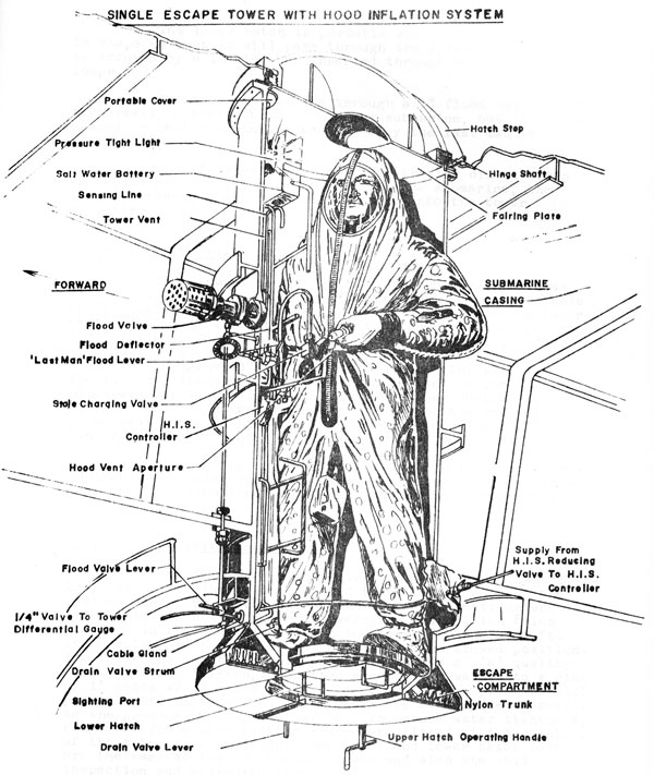
10.21 ONE MAN ESCAPE CHAMBER
ESCAPE PROCEDURE
Preparations in:
Submarine
Tower
A. Before Escape
1. Ship hatch operating handwheel and check in idle position.
1. Extend telescopic section of tower (Aft only)
2. Ship tower flood hand- wheel.
2. Open lower hatch.
3. Check inboard vent open.
3. Remove plug (Aft only).
10-22
Submarine
Tower
4. Check hull cock open for differential gauge.
4. Remove cover from salt water battery.
5. Check drain valve shut. Rig drain hose.
5. Lash pressure tight torch, switched on, in top of tower.
6. Switch tower light from ship's ring main to salt water battery.
6. Upper hatch lock to open. Detent engaged, handle removed, and fairing plate secured.
7. Open H.I.S. supply as follows: Check B.I.B.S. hull valve open Open B.I.B.S. diaphragm valve slowly Open B.I.B.S./H.I.S. cross connection Open H.I.S./Tower hull valve.
7. Test H.I.S. supply
8. Mark sea pressure reading on differential gauge.
8. Check flood valve free to open.
9. Remove cover from sightingport in lower hatch.
Put Tower through one complete unmanned cycle checking operation of all gear, gauges, etc.
B. Escape
1. Check both gags on stole in down position.
2. On noseclip, zip on hood.
3. Escaper enters tower and plugs into H.I.S.
4. Shut lower hatch.
5. Open flood.
6. When water level reaches the vent opening pressure will build up, top up lungs and clear ears alternatively until tower pressure equalizes with sea pressure.
7. When water flows through vent, shut vent.
10-23
Submarine
Tower
8. Put hatch operating gear as far as possible to open, ready to open fully as soon as pressures equalize.
9. Leave tower immediately hatch opens. Breathe normally during ascent.
C. After Escape
1. Shut upper hatch
2. Shut flood
3. Open drain
4. Open vent
5. Force lower hatch open to drain
6. Shut drain
8. Return upper hatch handwheel to idle.
After draining use all possible methods to remove excess water from compartment. Failure to do this will not prevent the full number of escapes being made, but the less pressure increase in the compartment the better. Repeat Escape Cycle.
D. Drill if Escaper Remains in Tower
1. Shut upper hatch
2. Shut flood
3. Open drain valve carefully and release tower pressure at 5 p.s.i. per second.
4. Open lower hatch. As this is oval it can be tilted and dropped through the hatch opening, requiring no co-operation from the occupant of the tower.
10-24
E. Drill for Last Man
As in 'B' except that he:
1. Collects vent cap from Red Cross locker.
2. Opens tower flood from inside tower.
3. Puts vent cap over vent when water reaches vent-top level.
4. Pushes upper hatch open himself.
NOTE 1 Should he fail to do 3. Equalisation of tower and sea pressure will still occur, but will take slightly longer.
Note 2 Action in 4 is normally not necessary as hatch opens by itself.
H.I.S. - HOOD INFLATION SYSTEM
10.22 BUILT IN BREATHING SYSTEM (B.I.B.S.)
10.23 AIM OF B.I.B.S.
The aim of the B.I.B.S. is to provide an unpolluted
Supply of air to escapers during the flooding up period and immediately prior to ascent. If escapers were allowed to breathe the atmosphere in the compartment during flooding up, they would be subjected to a rising partial pressure of carbon dioxide which, dependent upon depth and percentages of CO2 present before the start of flooding, might become lethal. Additionally, B.I.B.S. provides protection against other toxic gases which may be present such as chlorine and carbon monoxide.
10.24 METHOD
To achieve the vital requirement of an unpolluted supply of air for all escapers, it has been necessary, for reasons of space, to stow the large volume of air required in storage bottles outside the pressure hull. This air is piped to a supply manifold (inside the pressure hull in the Escape Compartment) to which a number of breathing units are attached. By this means the only equipment stowed in the Escape Compartment is the breathing units together with sufficient buoyancy and protection against exposure in the form of Submarine Escape immersion Equipments (S.E.I.S.) for every escaper.
10-25
10.25 GENERAL DESCRIPTION
From the external storage bottles the B.I.B.S. is led through the pressure hull and into the Escape Compartment. In the Escape Compartment there is a hull valve and a special sealed stop valve, known as the diaphragm valve. This is designed to retain the air at 4000 p.s.i. (dependent on temperature) throughout the commission of the submarine. On piercing the diaphragm valve the air is admitted to one of two differential reducing valves which reduces the pressure to 100 p.s.i. above compartment pressure and passes it straight to the manifolds running the entire length of the Escape Compartment. Sufficient quick release sockets are fitted to these manifolds to accommodate the entire crew, plus a few extra for passengers.
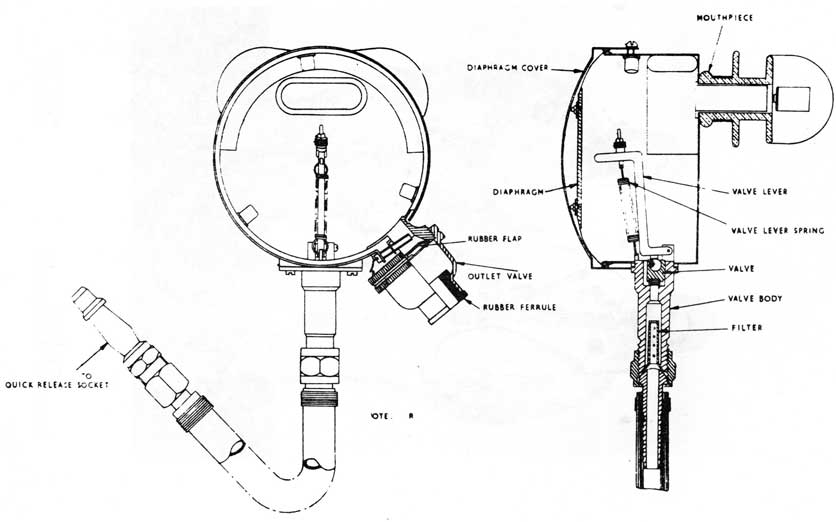
Prior to flooding up, the male connections, attached to rubber tubes, are plugged into the manifolds and the air is then admitted through these tubes to demand valves and mouthpieces, (Fig. 10) known as 'breathing units'. Inhalation through the mouthpiece will open the breathing unit valve and on exhalation the breath is exhausted into the compartment. Inflation of the stole of the S.E.I.E. is achieved by inserting the inflation tube into a special socket on the exhaust side of the breathing unit.
On completion of flooding the first escaper takes a deep breath, discards his breathing unit and makes a normal buoyant ascent, blowing out steadily all the way to the surface. As each escaper leaves the submarine the remainder fleet along from one breathing unit to the next until all have escaped.
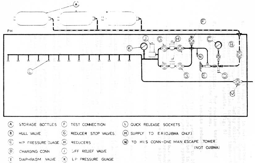
10.26 DETAIL (See Fig. 7)
A. Bottle Group. To hold large volume of air under
pressure 4000 p.s.i.). bottles stowed outside pressure hull.
B. Hull Valve. To enable bottle to be isolated in the event of damage or when connecting or disconnecting charging hoses. Valve normally kept wired OPEN.
C. H.P. Pressure Gauge. To indicate pressure in stowage bottles.
D. Charging Connection. For charging or topping up air bottles.
10-26
BUILT IN BREATHING SYSTEM
FIG 7
10-27
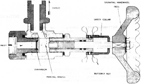
E. Diaphram Valve. A stop valve in H.P. system. Only opened when required for escape. Opened by piercing copper disc. Safety collar locked by butterfly nuts provided to prevent inadvertent operation of valve spindle. (Fig. 8)
F. Air Test Connection. For routine testing of reducers and L.P. side of system.
G. Reducer Stop Valves. To isolate reducers.
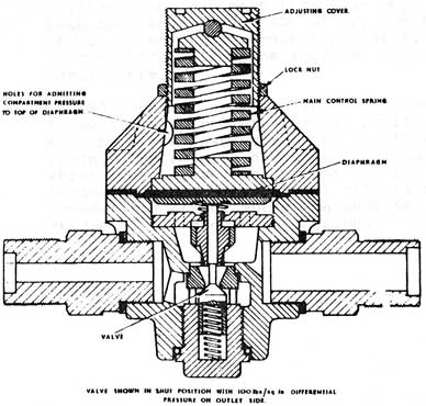
H. Reducers. To reduce bottle air pressure to 100 p.s.i. above compartment pressure. Fitted in duplicate, one only used when operating system. (Fig. 9)
J. Differential Relief Valve. To protect L.P. side of system, set to 150 p.s.i. above compartment pressure. Special spanner provided for adjusting purposes.
K. Pressure Gauge. To indicate pressure in L.P. side of system.
L. Quick Release Sockets. To accommodate male adaptors of breathing units.
M. Bulkhead Stop Valve. Fitted to supply supplementary escape compartment (Engine Room in Ojibwa only).
Manifold Test Fitting. Consists of an adaptor fitted with an L.P. gauge, a flexible connection to a male adaptor, and an orifice capable of passing 150 litres/min. of air at 100 p.s.i. Each submarine carries two test fittings.
10.27 CHARGING
1. All B.I.B.S. are to be charged with H.P. air,
which must be both clean and dry.
2. In order to prevent contaminated air reaching the B.I.B.S., submarines are to charge the systems using a compressor and observing the following precautions:
10-28
DIAPHRAGM VALVE FIG 8
DIFFERENTIAL REDUCING VALVE FIG 9.
10-29
(a) The main engines of the submarine must not be running.
(b) Charging must not be undertaken if there is either diesel exhaust from another submarine, or smoke from any other source present in the atmosphere.
(c) The hatch nearest to the compressor is to be open.
(d) The connections between the H.P. air line and the B.I.B.S. must be made with clean, oil free, flexible hoses and activated alumina filters drawn from dockyard.
(e) The filters must be recharged regularly.
3. Immediately on completion of charging, a sample of the air delivered by the compressor is to he taken and forwarded in a sealed bottle to the Medical Authorities for analysis. The charge shall be considered satisfactory if it contains at least 20.6% oxygen, not more than 0.1% CO2, not more than two parts in 100,000 of CO, and free of traces of oil or other dangerous impurities. A certificate to this effect is to be included with the charging certificate.
4. Should chemical analysis show that the charge is below the required standard of purity, the B.I.B.S. must he blown down as soon as possible and charged again. The results of the analysis will indicate which sources are responsible for the measured contamination and by careful attention to the precautions stated above, an acceptably pure
charge of air should be obtained.