C.F. 'O' Class Submarines - Air Systems, describes the air systems of the Oberon class submarines.
In this online version of the manual we have attempted to keep the flavor of the original layout while taking advantage of the Web's universal accessibility. Different browsers and fonts will cause the text to move, but the text will remain roughly where it is in the original manual. In addition to errors we have attempted to preserve from the original, this text was captured by a combination of optical character recognition and human typist. Each method creates errors that are compounded while encoding for the Web. Please report any typos, or particularly annoying layout issues with the Mail Feedback Form for correction.
Air in a submarine has many purposes. The working pressures will vary from a few pounds to a maximum of 4000 p.s.i.
Among the uses for H.P. air in a submarine are:
(i) Blowing out water ballast to surface
(ii) Blow 'Q' and 'D' tanks
(iii) Maintaining a pressure on the hydraulic system
(iv) Starting Diesel Generators
5.02 BASIC PRINCIPLES OF COMPRESSED AIR
The actuating force of the air systems is compressed air, which, as the name implies, is air under pressure confined within the limites of a container. The force required for compression of the air is provided by the high pressure air compressors, simple machines that compress air by means of a series of pistons designed so that one or more pistons discharges air into another for further compression and finally through lines to banks for storage. Air can be compressed easily aboard a submarine, as it requires a relatively small plant and comparatively simple equipment. It can be stored at any convenient place and is always ready for use. Its action can be regulated to produce a low or high pressure, and yet it has enough elasticity or compressibility to cushion its impact against the equipment it operates. It consumes no valuable materials and can be supplied to any part of the submarine simply by extending a line from the air supply. Air, once stored, requires no further expenditure of energy for operation, but rather is a source of power to other equipment.
5-2
C. F. 'O' CLASS SUBMARINES
CHAPTER 5 - AIR SYSTEMS
PART I - HP AIR SYSTEM
5.11 AIR STORAGE AND DISTRIBUTION
Compressed air for blowing tanks and for working various items of air-operated equipment is contained in 41 forged steel bottles charged by two electrically-driven air compressors, sited in the engine room and each capable of charging all air groups to 4000 lb/sq.in.
The bottles are arranged in five groups, connected either singly, in pairs, or in threes by 3/4 in. bore pipes, to five group manifold chests containing a number of stop valves for regulating air to or from the bottles.
An air line of 1 in. bore is led from each group manifold chest to a distribution valve chest positioned in the control room, port side. This chest is directly connected to both H.P. air compressors and also a ring main of 0.4375 in. bore run the length of the submarine. The ring main supplies H.P. air to a main blowing panel and an auxiliary blowing panel, thus providing centralised distribution of H.P. air to those tanks which require to be blown during surfacing and diving
operations.
The ring main has athwartships cross-connections which link the port and starboard runs. From the cross-connections, H.P. air to other services is tapped. It can be divided into forward and after sections by means of a stop valve fitted in the starboard run within the control room, which valve is normally kept shut.
Nos 1, 2, 3 and 4 air bottle groups can be fed into Nos. 1, 2, 3 and 4 cross-connections respectively and No. 5 group into No. 7 cross-connection.
Bulkhead stop valves on the ring main, and salvage blows fed from their nearest cross-connection, are fitted on the control room side of each main watertight bulkhead.
5-3
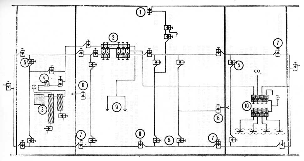
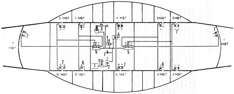
(Figure 1)
Typical HP Air System
1. Shore charge Hull Valve
2. Main Distribution panel
3. Compressor system and separators
4. Surplus air valve
5. Ring Main Cross Connections
6. Compartment Blows
7. Bulkhead Stop Valves
8. Fwd/Aft Ring Main Cross Connection
9. Main and Aux. Blows
10. Bottle Group
5-4
5.11 AIR STORAGE AND DISTRIBUTION (CONTD)
Capillary brazed couplings are generally used to join sections of the H.P. air ring main piping. Screwed unions are, however, employed where the ordinary capillary brazed type is unsuitable.
A 3/8 in. shore charging connection is fitted immediately forward to the bridge fin and conveys air via a hull valve and stop valve to No. 4 cross-connection. A water test plug is fitted between these valves.
Before installation all H.P. air pipes and fittings are water pressure tested to 6000 lb/sq.in., and after, to 5000 lb/sq.in. up to the individual air bottle stop valves.
Air from the H.P. air ring main can be opened up to an L.P. air system.
The ring main also supplies air storage bottles for air-aided escape purposes.
5.12 HP AIR SYSTEM FITTINGS
A. Stop Valves
The H.P. air ring main stop valves are of 3/4 in. nominal bore. They are screw-down balanced valves, each with one inlet male connection and one outlet male connection screwed l 1/2 in. B.S.P. for a pipe coupling nut. The pipe union joints are made with O-rings.
B. Group Manifolds
A group manifold chest is provided for each group of air storage bottles to regulate the inlet or outlet of air into or out of the bottle group. The chest also serves to distribute H.P. air from the air bottle storage group to equipment and services as illustrated.
The shut-off valves on the chest are similar in design to an ordinary H.P. air stop valve.
Connecting pipes are attached to the chest by pipe couplings connected to adaptors screwed and sweated into the chest body.
5-5
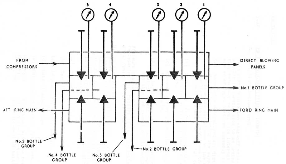
(Figure 2)
Main Distribution Panel
(10 Valve Chest)
5-6
5.12 HP AIR SYSTEM FITTINGS (CONTD)
C. Main Distribution Panel
This chest houses ten shut-off valves each similar in construction to an ordinary H.P. ring main stop valve. Its internal passages are so arranged that the assembly can be used to:
(a) Serve as a centralised air distribution station for regulating the supply of H.P. air from the air groups to the main and auxiliary blowing panels and thence to the main ballast, 'D' and 'Q' tanks.
(b) Serve as a junction between the forward and after sections of the H.P. air ring main.
(c) Connect any or all of the air groups to the ring main.
(d) Allow air from the compressors to be discharged direct into the ring main, and into any selected number of air bottle groups.
Pressure gauges are fitted to the chest, each gauge registering the pressure in the particular air group opened up to the chest.
D. HP Air Bottles
Bottles are generally stowed vertically, but those which are stowed horizontally are inclined 5 degree neck up. Internal pipes
are run from the lowest point to the air connection. Thus any water collecting within a bottle is blown out when the air is used. All air bottles are marked with:
(a) The makers initial
(b) Serial number
(c) An Admiralty serial number
(d) Date of manufacture
(e) Date and pressure of first test
History sheets are issued with the bottles and are kept up to date by the insertion of results of all tests and the movement of bottles.
5-7
5.12 HP AIR SYSTEM FITTINGS (CONTD)
E. Bottle Groups
(i) Number 1 H.P. Air Bottle Group
Eight bottles
Starboard side for'd accommodation space
Capacity per bottle 3.74 cu. ft.
(ii) Number 2 H.P. Air Bottle Group
Eight bottles
Port side for'd accommodation space
Capacity per bottle 3.74 cu. ft.
(iii) Number 3 H.P. Air Bottle Group
Fourteen bottles
Seven each side of control room
Capacity per bottle 3.74 cu. ft.
(iv) Number 4 H.P. Air Bottle Group
Six bottles
Externally under casing for'd of the fin
Capacity per bottle 9.1 cu. ft.
(v) Number 5 H.P. Air Bottle Group
Five bottles
After torpedo stowage compartment
Capacity per bottle 9.1 cu. ft.
Group with Largest Air Capacity
Number 4 bottle group has largest capacity normally opened up to direct blowing panel.
F. Groups Supplying H.P. Air to CO2 Absorbtion Unit
(i) No. 1 and 2 group manifolds supply H.P. air direct to for'd CO2 Absorbtion Unit.
(ii) No. 4 and 5 group manifolds supply H.P. air direct to after CO2 Absorbtion Unit.
5.13 DIRECT HP AIR BLOWING SERVICES
H.P. air at full pressure is used for blowing main ballast tanks (Nos. 1, 2, 4, 6 and 7), 'D' tanks and 'Q' tank, the air being supplied through direct lines, led for the main ballast tanks from the main blowing panel, and for 'D' tanks and 'Q' tank from the auxiliary blowing panel.
5-8
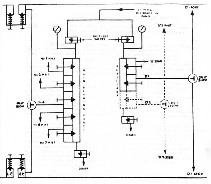
(Figure 3)
Main and Auxiliary Blowing Panels
(Showing 4 MBT HP/LP Tanksides)
Section shown in dotted lines represents the additional blow to D2 tank, fitted in OJIBWA only.
5-9
5.13 DIRECT HP AIR BLOWING SERVICES (CONTD)
NOTE Nos. 3 and 5 main ballast tanks (external oil fuel
tanks) are provided with hand-operated kingstons and can be blown with L.P. air only.
The main blowing panel consists of five 1 in. bore master blow valves grouped together one above the other. They are each similar in design to an ordinary H.P. air ring main stop valve except that each valve is operated by a short quick acting 'T' handle. The panel may be isolated from the main distribution panel by a shut-off valve and is provided with a pressure gauge and a drain valve.
The H.P. air from the master blow valves is supplied to the main ballast tanks (Nos. 1, 2, 4, 6 and 7) through combined H.P. and L.P. tank side valves, in addition a
split blow valve is fitted to No. 4 main ballast tank (P and S). Each combined valve consists of a 1 in. bore S.D.N.R. spring-loaded H.P. air tank-side valve, screwed into the side of a 2 in. bore L.P. air tank-side valve. An air-tight seal between the two valve bodies is maintained by an O-ring.
The split blow comprises two quick-acting screw-down shut-off valves and functions to maintain athwartships trim when surfacing. Each shut-off valve is similar in design to an ordinary H.P. air stop valve. The valves are housed in a common casting. The top of each valve operating spindle is provided with a pinion, which meshes with a central gear wheel operated by a hand lever as illustrated. Movement of the hand lever shuts one valve and opens the other and, with the hand lever in the central position, both port and
starboard tanks will be blown equally.
The auxiliary blowing panel situated adjacent to the main blowing panel contains two master blow valves (Q & D) and is fitted with an isolating valve, a drain valve and a pressure gauge. 'Q' tank is blown via a hull tank-side S.D.N.R. valve and D (P and S) via a split blow and
S.D.N.R. hull valves.
A 400 lb/sq.in. relief valve with a hull shut-off valve is fitted to 'Q' tank and each 'D' tank.
Differential pressure gauges sharing a common sea inlet are provided in the control room for 'Q'., 'D' and 'O' tanks.
5-10
5.14 REDUCED HP AIR SERVICES
Two methods are used for reducing H.P. air to the required working pressure, they are:
(a) Automatic Reducing Valves. These are preset to give the required outlet pressure and when the inlet STOP VALVE is opened no further regulating is needed. A pressure gauge is provided as a check and a relief valve as a safety measure.
(b) Hand Reducers. In addition to the Stop Valve, a REGULATING VALVE is provided which is adjusted. to give the required outlet pressure. A pressure gauge is provided as a check, and a relief valve as a safety measure.
List of Reduced Blowing Stations that may be found on each cross-connection. It is not complete. The trainee will find slight differences in each submarine.
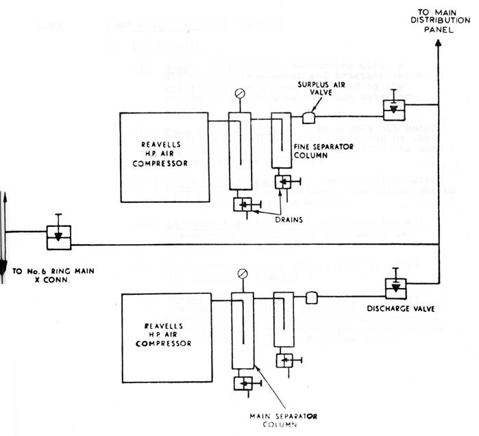
Two electrically driven Reavells TC4 H.P. air compressors are fitted in the engine room. Cooling water is provided by the after services system on the surface or when snorkelling, but when deep the compressors' own pumps can take a suction from 'W' tank.
Air is drawn into the compressor and compressed in succession by pistons to a pressure of 4000 p.s.i.
1st stage
38 - 42 p.s.i.
2nd stage
230 - 250 p.s.i.
3rd stage
890 - 950 p.s.i.
4th stage
Line Pressure or 4000 p.s.i.
From the compressor the air passes through two separator columns which remove any water or oil suspended in the air.
From the separators the air passes through a surplus air valve which does not open until a pressure of 3,500 p.s.i. is reached in the separator columns. This is to assist in separating moisture contained in the air and prevents pressure fluctuating when changing groups.
Finally the air passes the shut off valve to either the main distribution panel or the engine room ring main cross connection.
5.22 COMPRESSOR CIRCUITS
A. Air Circuit
(i) Pistons & Plungers - to compress air taken
from the atmosphere to 4000 p.s.i. in four stages, The pistons are worked by a crankshaft driven by an electric motor.
5-13
5.22 COMPRESSOR CIRCUITS (CONTD)
A. Air Circuit (contd)
(ii) Suction and Discharge Valves - to enable pumping action to take place in each cylinder.
1st and 2nd stages - plate valves
3rd and 4th stages - thimble valves
(iii) Relief Valves - to protect each stage from
excess pressure in the event of valve
failure of the following stage.
Settings:
1st stage - 65 p.s.i.
2nd stage - 360 p.s.i.
3rd stage - 1300 p.s.i.
4th stage - 4200 p.s.i.
(iv) Pressure Gauges - to indicate stage pressures.
B. Water Circuit
(i) Coolers - to cool air after it has been compressed in each stage.
1st and 2nd stage - tube type
3rd and 4th stage - coil type
(ii) Pump (Impeller Type) - to circulate water through the coolers and around jackets. Driven by the crankshaft the pump discharges to the combined 3rd and 4th stage and oil cooler, thence to the bottom of the jackets which also house the 1st and 2nd stage
coolers and then from the top of the jackets discharges overboard.
(iii) Drain Bottles and Cocks - to collect and drain off water vapour that is condensed during cooling.
(iv) Relief Valve (60 p.s.i.) - to protect the system from excess sea pressure through the combined 3rd, 4th stage and lube oil cooler.
(v) Bursting Disc. (Copper foil) - to protect the jackets against a sudden rise in sea pressure due to a burst cooler tube or coil in the 1st and 2nd stage cooler.
5-14
(Figure 4)
Compressor Discharge Circuits
5-15
5.22 COMPRESSOR CIRCUITS (CONTD)
C. Oil Circuit
(i) Sump - to hold the lubricating oil. A dip stick, thermometer and breather valve are fitted and a cock is fitted to the bottom of the sump to test for water or sludge.
(ii) Pump (Eccentric Type) - to supply oil under pressure to bearings. It is driven by the crankshaft and takes a suction from the sump through a gauze strainer.
(iii) Filter (Autokleen) - to prevent solid matter from going to the bearings. The filter can be cleared by rotating a handle.
(iv) Adjustable Relief Valve - to keep correct pressure at bearings and is usually set to lift at 25 p.s.i.
(v) Cooler - to prevent oil overheating (3rd and 4th stage cooler)
(vi) Mechanical Lubricator - is driven by the crankshaft and delivers oil at the rate of 2 drops per minute to the 3rd and 4th stage piston rings. The 1st and 2nd stage pistons are splash lubricated from the sump.
5-16
C.F. 'O' CLASS SUBMARINES
CHAPTER 5 - AIR SYSTEMS
PART III - LP AIR SYSTEM
5.31 INTRODUCTION
The low pressure air system is used to remove the residue of water from the main ballast tanks after they have been blown with H.P. air, thus bringing the submarine to full buoyancy and effecting an economy of H.P. air. It has the following additional uses:
(i) Vacuum and pressure testing of the submarine can also be carried out using the system.
(ii) H.P. air can be passed to the main ballast tanks in an emergency through the L.P. Air System by means of an H.P. to L.P. cross connection valve.
(iii) Excess pressure in the submarine can be removed before opening the conning tower hatch on surfacing.
(iv) Buoyancy is maintained when the submarine is on the surface by "blowing round" on MBT, this is particularly important in rough weather.
5.32 LP AIR FITTINGS
A. LP Master Blows
These valves provide a ready means of shutting off each main ballast tank from the L.P. line from central positions in the control room. These valves are only opened by order of the Officer of the Watch when preparing to surface or during other evolutions.
When carrying oil fuel in number 3 and 5 main ballast tanks their Master Blows are lashed shut.
5-17
(Figure 5)
Typical LP Air System
1. LP Blower
2. Blower Discharge Valve
3. E.B.S. Differential Relief
4. HP to LP Blow Valve (E.B.S.)
Shut off the air line at the pressure hull, and are spring-loaded non-return valves, they prevent water from entering the L.P. line when the main ballast tanks are flooded. They are attached to each individual ballast tank in the same valve chest as the H.P. tanksides. The L.P. tanksides are normally kept open. L.P. tanksides to number 3 and 5 ballast tanks are kept shut and lashed when those tanks are carrying oil fuel. Individual tanksides can be shut in order to correct a list.
C. Emergency Blowing Station (Blowing HP to LP)
Provides a means of surfacing the submarine using H.P. air if the main blowing panel is out of action and obtaining full buoyancy if the blower is out of action.
It is situated in the control room, connected to
the L.P. air line from number 4 ring main
cross connection on the H.P. air system by an H.P. to L.P. air regulating valve.
A relief valve is located on the L.P. air main line and is set to lift at 15 p.s.i. above sea pressure. When blowing H.P. to L.P. the air pressure is regulated below 10 p.s.i. above sea pressure and to facilitate this a differential pressure gauge is fitted.
The L.P. line is tested to full diving pressure so that the Emergency Blowing Station can be used at any depth.
5-19
C.F. 'O' CLASS SUBMARINES
CHAPTER 5 - AIR SYSTEMS
PART IV - L.P. BLOWER
5.41 INTRODUCTION AND DESCRIPTION
The blower consists of a rotor mounted eccentrically in its casing. A perforated drum, free to revolve, is fitted between the rotor and the casing. Six radial slots, each containing a vane are cut in the rotor, the vanes being free to move in or out as the rotor turns. The gap between the rotor and the perforated drum is a minimum at the top and the maximum at the bottom so that as the rotor revolves each vane will move out centrifugally as it travels from the top of the drum to the bottom and in again as it returns to the top. The extended vanes divide the space between the rotor and the drum into segments, whose volumes increase as the vanes move from top to bottom and decrease as they move back to the top.
When the rotor is turning the vanes grip the perforated drum causing it to rotate thus minimizing wear at the vane tips. Air is drawn in through the inlet as the volumes increase and is discharged through the outlet as they decrease. This positive displacement of air builds up a pressure in the L.P. air line.
Air is delivered to the main ballast tanks at a pressure of up to 15 p.s.i. As the blower draws air from the atmosphere it is not started until the conning tower hatch has been opened, except when carrying out a vacuum test.
The blower should not be run for more than 20 minutes as no special cooling arrangements are fitted. In service it is not run for more than 11 minutes and at least two LP Master Blows must be opened.
A blower discharge valve is fitted to shut the blower off from the L.P. line and is always kept shut when the blower is not in use.
A filter is fitted to the inlet range of the blower casing to prevent dirt entering and damaging moving parts.
A drain cock is fitted on the outlet side of the blower discharge valve and is used to drain off any water that may be in the line before starting the blower. It is kept shut except when starting and stopping the blower. A relief valve set to 15 p.s.i. is also fitted on the line to protect the L.P. system and main ballast tanks.
5-20
5.41 INTRODUCTION AND DESCRIPTION (CONTD)
A mechanical lubricator is fitted to feed small quantities of oil to each vane through axial and radial holes in the rotor.
A water filled sight glass is fitted in the discharge pipe and the rate of feed is adjusted to supply 4 or 5 drops of oil per minute.
A grease lubricator is used to lubricate roller bearings on the motor end. Other bearings are lubricated by an 'oil mist' created inside the blower by an oil feed to the vanes from the mechanical lubricator.
5.42 HULL AND COMPARTMENT TESTS
The L.P. blower is used to put on two types of test to the submarine.
A. Vacuum Test
To ensure that all pressure hull fittings above the water line are watertight before diving the submarine a vacuum test is carried out usually after maintenance periods in harbour. All hatches are shut and the blower run on the main ballast tanks to create a slight vacuum in the whole of the submarine, any leaks are readily heard or detected by means of a lighted taper.
B. Pressure Test
A pressure test ensures that a compartment is watertight after any work has been carried out on its bulkhead fittings. Test blanks must be removed from the L.P. line in the compartment. The compartment is then sealed and the blower is run until a pressure of 10 - 15 p.s.i. is reached, any leaks being readily heard or detected by means of soapy water.