20 MM Antiaircraft Gun, OP 911, 1943, is a Navy service manual for the anti-aircraft gun of choice during the early years of WW II.
In this online version of the manual we have
attempted to keep the flavor of the original layout while taking advantage
of the Web's universal accessibility. Different browsers and fonts will cause
the text to move, but the text will remain roughly where it is in the original
manual. In addition to errors we have attempted to preserve from the original
this text was captured by optical character recognition. This process creates errors that are compounded while encoding for the Web.
How to strip a right hand magazine has a couple of errors in the printed text. Page 72, relieving magazine spring tension, step 1 the handle should be on the ratchet for the spring, i.e. fig 58 instead of 63. Also in step 5, it should repeat step 2 instead of 3. Step 10 leaves out the removal of the screw, retaining ring, spring and sleeve. Note the instructions on how to tension, load, unload, and strip a left hand magazine in the twin mount are all slightly different (tensioning clockwise vs counter-clockwise) from a right hand magazine. However, they are better instructions so read them before attempting a right hand magazine.
Please report any typos, or particularly annoying layout issues with the Mail Feedback Form for correction.
Please make the following corrections on the pages listed below:
PAGE NO.
CORRECTION
85
Tenth line up from bottom of page-change-(300021-6) to read (300021-7).
86
Figure 70 at top of page-change (300021-6) to read (300021-7).
87
Twelfth line down from top of page-change-(300021-6) to read (300021-7).
87
Last paragraph on page-Alternate Rear Sight Pin Tips-Mark 5 Sight-delete this entire paragraph.
ORDNANCE PAMPHLET NO. 911
20 mm. A.A. GUN
20 MM. MACHINE GUN MECHANISMS MARKS 2 AND 4
20 MM. GUN BARRELS MARKS 2, 3, 4, AND 4 MOD. 1
20 MM. SIGHTS MARKS 2, 4, 4 MOD. 1, AND 5
20 MM. MAGAZINES MARKS 2 AND 4
20 MM. SHOULDER RESTS MARKS 2, 4, 5 AND 5 MOD. 1
DESCRIPTION
MARCH, 1943
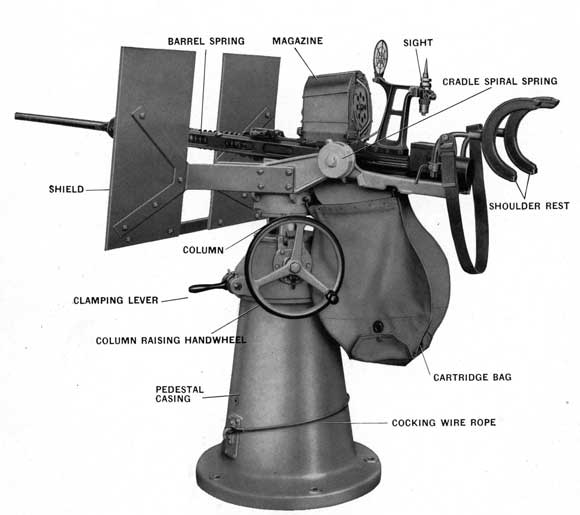
20 mm. A. A. Gun on Mark 4 Mod. 3 Mount
3
PREFACE
This Ordnance Pamphlet, No. 911, is a revision of the Gun Section of Ordnance Pamphlet No. 813 and describes the construction, operation, and maintenance of the 20 mm. A.A. Guns.
Additional Ordnance publications relating to the use of the 20 mm. A.A. Guns are:
O.P. 909
-20 mm. Mounts Mark 2, Mark 2 Mod. 1, Mark 2 Mod. 2; Mark 4, Mark 4 Mod. 1, Mark 4 Mod. 2, Mark 4 Mod. 3; Mark 5, Mark 5 Mod. 1, Mark 5 Mod. 3, Mark 5 Mod. 4; Mark 6; Mark 10 and Mark 10 Mod. 1.
O.P. 945
-20 mm. A.A. Range Tables.
O.D. 4429
-Gun Sight Mark 14 Mod. 2-Installation and Operation.
SK. No. 103308
-20 mm. Machine Gun and Mount Index.
Ordalt No. 1186
-20 mm. Cradles Marks 2 and 4-Instructions for Necessary Modification for Assembly of Gun Sight Mark 14.
Ordalt No. 1226
-20 mm. Machine Gun Mechanism Marks 2 and 4 20 mm. Hand Grips and Shoulder Rests Marks 2 and 4-Instructions for Adding Drainage Holes.
Ordalt No. 1269
-20 mm. Cradle Mark 2 and Mark 2 Mod. 1. 20 mm. Cradle Mark 4 and Mark 4 Mod. 1-Instructions for Installation of Cocking Sheave.
Ordalt No. 1300
-20 mm. Shield Mark 2; 20 mm. Shield Mark 4-Instructions for Modification of Shield Brackets.
Ordalt No. 1366
-20 mm. Cradle Mark 2 and Mark 2 Mod. 1. 20 mm. Cradle Mark 4 and Mark 4 Mod. 1-Instructions for Cradle Modification to Facilitate Disassembly.
Ordalt No. 1395
-20 mm. Shields Marks 2 and 4-Improvement of Sight.
Ordalt No. 1398
-20 mm. Mounts Marks 2 and 4-Changes to Improve Lubrication.
Ordalt No. 1457
-Modification of 20 mm. Sight Mark 4 Mod. 1.
The Mark 1 Gun was the original type made in Switzerland. The Mark 2 is the improved version made in England and also being made in U. S. A. The Mark 4 Gun is almost identical with Mark 2 except for slightly different manufacturing limits. Both Marks 2 and 4 Guns will be found in service in the U. S. Navy, but eventually only the Mark 4 will be manufactured in this country.
4
INTERCHANGEABILITY
There is very little difference, from the operating point of view, between
Mark 2-British
Marks 2 and 4-U.S.N.
All of the above three Marks of assembled guns are interchangeable as units. There are certain differences in the Marks 2 and 4 guns that affect interchangeability of parts. When individual parts are not interchangeable between Marks 2 and 4, the assembly or the subassembly containing these parts is usually interchangeable.
AMMUNITION
The ammunition is common for Marks 1 and 2 (British) and Marks 2 and 4 (U. S. N.) Guns.
5
TABLE OF CONTENTS
NOTE-Plate 1 is the folded insert of the gun assembly at page 160.
Rotate 60 Degrees and rotate locking lever into slot in barrel
Barrel Spring Compression (breech block in extreme forward position)
Rectangular Wire
72 Pounds
Round Wire
130 Pounds
Barrel Spring Compression (metal to metal contact between barrel spring case and buffer)
Rectangular Wire
535 Pounds
Round Wire
374 Pounds
Barrel Spring Compression, Full Recoil (metal to metal contact between buffer and breech casing)
Rectangular Wire
576 Pounds
Round Wire
396 Pounds
Buffer Spring Compression, 12 Springs, Full Recoil (metal to metal contact between buffer and breech casing)
Rectangular Wire
2508 Pounds
Round Wire
2220 Pounds
Total Compression Barrel Spring and Buffer Springs, Full Recoil (metal to metal contact between buffer and breech casing)
Rectangular Wire (Barrel and Buffer Springs)
3084 Pounds
Round Wire (Barrel and Buffer Springs)
2616 Pounds
RANGE
Maximum at 45 Degrees Elevation
Approx. 4800 Yds.
12
WEIGHTS
Gun Barrel and Mechanism (Ribbed Barrel)
141 Pounds
Gun Barrel and Mechanism (Solid Barrel)
150 Pounds
Sight-Marks 2, 4, and 4 Mod. 1
13 Pounds
Sight Mark 5
7 Pounds
Shoulder Rest-Marks 2 and 4
20 Pounds
Shoulder Rest-Mark 5
28 Pounds
Shoulder Rest-Mark 5 Mod. 1
25 Pounds
Magazine-Marks 2 and 4-Loaded
63 Pounds
Magazine-Marks 2 and 4-Unloaded
31 Pounds
13
14
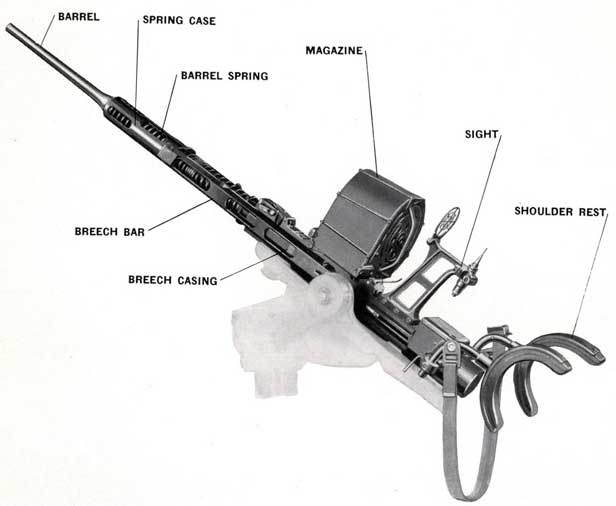
COMPONENT PARTS
Figure 1-Exterior view showing general arrangement
of the Mark 4, 20 mm. A. A. Gun
15
MAJOR COMPONENTS-MARK 4 AND MARK 2
Chapter 2 GENERAL DESCRIPTION OF GUN OPERATION
FEATURES
The Marks 2 and 4 Gun Mechanisms, as stated in the "Preface" on page 3, operate the same. They are for close range, high angle fire as an antiaircraft defense. Each is singly mounted upon a pedestal and is capable of being trained through 360 degrees. The elevation limits on the guns mounted on Mark 2, Mark 4, and Mark 5 Mounts are from 5 degrees below horizontal to 87 degrees above horizontal except on Mark 4 Mod. 3 on which elevation is 90 degrees. Those mounted on Mark 6 and Mark 10 Mounts have elevation limits from 15 degrees below horizontal to 90 degrees above horizontal.
PRINCIPLE OF CONSTRUCTION
The major difference between this gun and others is that the force of the explosion is absorbed in checking and reversing the forward movement of a relatively heavy bolt, or breech block, that is never locked. In most guns the force of the explosion is taken by the locked breech block and by the recoil cylinders and mechanism. See Figure 2.
FIRING
The gun fires automatically as long as the trigger is pressed and there is ammunition in the magazine. When the last round of each magazine is loaded into the gun and fired, the trigger mechanism is returned automatically to the cocked position regardless of the position of the trigger. This feature prevents the breech block mass from counterrecoiling on an empty gun after the last round is fired and, because there is no explosion to reverse the breech block, a recocking by hand would be necessary before firing could be continued. A Safe/Fire lever is fitted close to the right hand grip. See Figure 32. The rate of fire is approximately 450 rounds per minute.
The magazine is easily and quickly changed. It is retained by lugs on its fore end and a magazine catch at the rear. See Figure 18.
GUN
The gun is considered to consist of the following three units. Sec Figure 1.
1. The gun barrel
2. The machine gun mechanism
3. The shoulder rest and hand grips
The sight and magazine are considered as supplementary units required to complete the assembly.
MAGAZINE
The ammunition is supplied from a magazine that holds 60 rounds. The magazine is detachably mounted on the gun. It is filled, also serviced while removed from gun.
MOUNT
The mount includes the cradle in which the gun is fixed, the carriage which carries the oscillating parts, and the stand which is bolted to the deck. For complete information on mounts, see Ordnance Pamphlet No. 909.
16
COMPONENTS
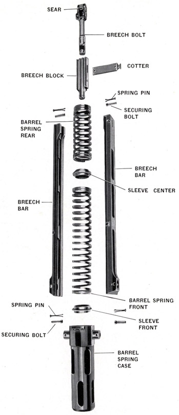
Figure 2-Recoiling Parts
17
OPERATING FEATURES
The more important features of the operating principle of the Mark 2 and Mark 4, 20 mm. A.A. Guns are as follows:
(A). The breech casing and barrel do not recoil.
(B). The recoiling parts are the breech block and the parts that connect it to a powerful two-piece barrel spring. See Figure 2. The breech block recoils and counterrecoils with a purely reciprocating action.
(C). The barrel spring is the only force tending to keep the breech block closed. There is no positive lock.
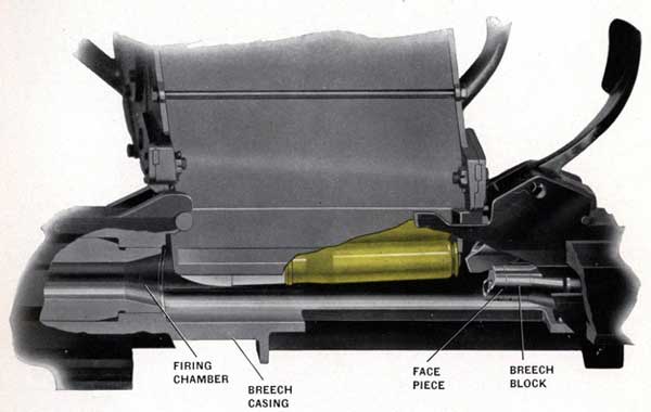
Figure 3-Loading Mechanism in cocked position. Breech block in
position to pick up cartridge when trigger is released
(D). Preparatory to opening fire, the breech block must be pulled back, see Figure 3 and gun assembly Plate 1, until, the sear (OE-1317) is held by the trigger hook (OE-1216). This compresses the barrel springs (OE-1320 and 1321) and causes a pull on the recoiling parts being held in the cocked position by the trigger hook.
(E). Pressing the trigger releases the breech block allowing it to move forward, under the pull of the barrel spring.
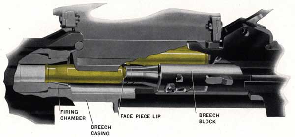
(F). A round of ammunition is picked up from the magazine by the breech block on its way forward and is carried toward the gun barrel. At a point about half way forward, the next round in the magazine forces the cartridge down into the lip of the breech face piece as shown in Figure 4.
18
Figure 4-Operation of Loading Mechanism about half way of forward stroke
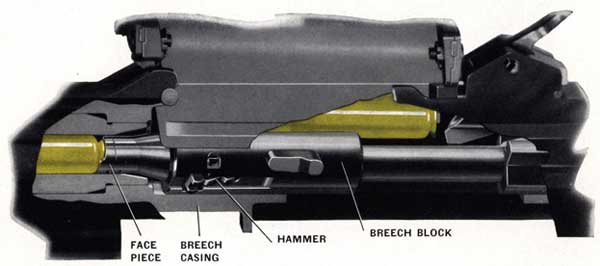
(G). Just before the breech block reaches the fully forward position, a striker pin in the breech block is operated by a hammer in the breech block and fires the round. A hammer plate in the breech casing operates the hammer as the breech block travels on recoil and counterrecoil inside the breech casing. Figure 5.
(H). When the round fires, the gas pressure first absorbs the forward momentum of the breech block and then blows the latter backward, thereby compressing the barrel spring which absorbs the rearward momentum imparted to the breech block by the gas pressure. The breech block is blown backward until at full recoil, it is to the rear of the position at which the trigger hook catches it. See Figure 31.
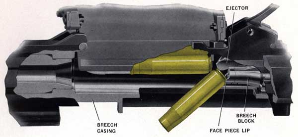
(I). As each round fires, the empty cartridge case together with the breech block is blown back from the chamber by the gas pressure. Subsequently the empty case is tipped out of the breech face piece by striking against an ejector in the breech casing. See Figure 6. The next round in the magazine is forcing the empty cartridge downward.
Figure 5-Cartridge Fired
19
Figure 6-Breech Block returning to cocked position Empty cartridge being ejected
(J). When all the rearward momentum has been absorbed by the barrel spring, the counterrecoil of the barrel spring forces the breech block forward again. On its way, the breech block picks up the next round from the magazine and the firing sequence is continued as long as the trigger is kept pressed or until the magazine is emptied.
(K). Whenever pressure on the trigger is released, the breech block is caught on the next attempt to commence its counterrecoil and is held in the cocked position. See Figure 3. This happens in all cases when there is ammunition in the magazine. In case the pressure on the trigger is maintained and the magazine becomes empty then the trigger mechanism is returned automatically to the cocked position regardless of the position of the trigger. See Figure 24.
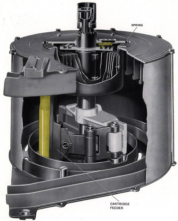
(L). The magazine, see Figure 7, consists of a cylindrical drum containing a clock spring that forces a cartridge feed block around a spiral in the magazine forcing the rounds down into the magazine mouth, where they are picked up by the breech block as it counterrecoils. A detailed description of the magazine action is given on Page 65.