(b) Securing bolts (OE-1323) and spring pins (OE-1324)**, secure barrel spring case to breech bars.
(c) Securing bolts (OE-1323) and spring pins (OE-1324)**, secure breech bars to breech bolt cotter.
5. Barrel spring case (OE-1102)*, mounted on the forward portion of the barrel.
6. Barrel springs (OE-1320 and OE-1321)***, mounted on the center portion of barrel, between the barrel spring case and the breech casing.
*Later model guns use a new barrel spring case with which front sleeve (OE-1318) is not used. See Page 147.
**Later model guns use a wire spring type securing bolt retainer (299666-4). See Page 135.
***Later model guns use new round wire barrel springs numbers (367533-2) front and (367533-1) rear. See Page 148.
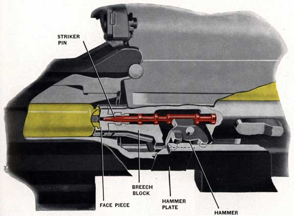
Figure 44-Breech bolt traveling forward with cartridge
Hammer holding striker pin to rear
58
In addition to the barrel springs (OE-1320 and OE-1321), Figure 43, there are two sets of buffer springs. A set of twelve (OE-1327) are mounted in the front end of the gun casing to cushion the last inch or so of recoil, Figure 46. A set of fifteen (OE-1326) in the trigger casing cushions the shock on the trigger mechanism when the trigger hook stops the gun in the cocked position, Figure 24.
STRIKER GEAR
The action of the striker gear is shown in Figures 44 and 45 showing the striker pin being held to rear when the breech bolt is traveling forward; the hammer imparting a blow to the striker pin and the striker pin being withdrawn by the hammer.
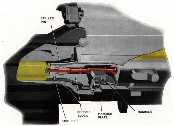
NOTE-The striker pin reaches its full firing travel by momentum and not by a direct thrust all the way by the hammer.
In order to understand the action of the hammer it should be noted in Figures 44 and 45 that the front toes and rear toe are positioned out of line with each other. There are two front toes, one on each side of the hammer. The rear toe is an extension of the center part of the hammer. The upper part of the hammer rests in, and operates, the striker pin. The hammer plate is secured to the breech casing and has a center cam surface, to operate the rear toe of the hammer and impart a thrust on the striker pin. Momentum carries the striker forward, thus firing the cartridge. See Figure 45. The hammer plate has two other cam surfaces, one on each side, to operate the hammer front toes and thus withdraw the striker pin from the
Figure 45-Breech bolt has carried cartridge into position to be fired. Rear hammer toe on hammer plate; front hammer toes in recess in breech casing
59
fired cartridge. The hammer plate cam surfaces are arranged so that the front toes are clear when the rear toe is operating, and the reverse is also true.
The three conditions of the operation of the striker gear are:
1. Breech block is traveling forward; Figure 44, it has picked up a cartridge, but has not quite reached the firing chamber. All three hammer toes are riding against the side of the breech casing, thereby holding the striker pin to the rear. The rear toe is about to strike the rear end of the center cam surface of the hammer plate.
2. The breech block has reached the end of its travel, Figure 45. The cartridge is being fired. The rear toe of the hammer is riding on the center cam surface of the hammer plate, causing the hammer to rotate forward. The hammer has driven the striker pin fully forward penetrating the primer of the cartridge. The front toes have entered a cutaway recess in the breech casing.
NOTE-THE STRIKER PIN SHOULD PROTRUDE 0.045 INCH TO 0.070 INCH FROM THE BREECH BOLT FACE PIECE WHEN THE STRIKER PIN IS FULLY FORWARD. See Maintenance Instructions on Page 142.
3. The breech block has started on recoil carrying with it the fired cartridge, Figure 44. The front toes have ridden up the front slope of the hammer plate causing the hammer to rotate rearward. The hammer has retracted the striker pin from the fired cartridge.
BREECH BLOCK
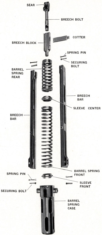
The breech block is connected to the breech bolt by the same cotter that connects the breech bolt to the breech bars. See Figure 43. The purpose of the breech bolt is to extend the breech block to the rear, in order to contact the trigger group. The breech bolt carries the recoil sear at the rear on an axis bolt. The right and left breech pawls are near the rear of the breech bolt. The recoil sear and breech pawls work with the trigger group as described on Page 42 and illustrated on Page 43.
The breech block face piece, Figures 44 and 45, is mounted in the front end of the breech block. It is retained by a shoulder that fits into a recess machined in the breech block, and is locked in place by a leaf spring. A hole is drilled in the center of the breech block face piece for the forward end of the striker pin. A cartridge carrier lip is integral with the front of the face piece, to carry the rear end of the cartridge case.
BREECH BARS
The breech bars are connected at the rear by the breech bolt cotter that passes through the breech block and its extension, the breech bolt, Figure 43. The breech bars are connected at the front to trunnions formed on the barrel spring casing. The trunnions fit in holes in the breech bars. Tubular securing bolts that are secured by two-legged spring pins fasten the breech bars to the barrel spring casing trunnions at the front, and to the breech bolt cotter at the rear. See Figure 43. New type breech bar securing bolt retainers (299666-4) made of round wire are now used. Instructions covering their installation and removal may be found on Page 135.
The right and left breech bars have hardened stop plates that contact the double loading stop whenever a portion of a torn cartridge case remains in the firing chamber under the double loading stop pin. See Page 34 for description and illustration of "Double Loading Stop."
BARREL SPRINGS AND CASE
There are two barrel springs; a long front one in the barrel spring case and a short rear one, with a center sleeve between them, See Figure 43. These springs are wound in opposite directions so as to prevent
60
twist on the spring casing and on the breech bars that might be caused by twisting of a single spring. The purpose of these springs is to absorb the rearward momentum of the recoiling parts, and to return these parts to their forward position.
NOTE-The compression on the rectangular barrel springs is 72 pounds and on the round wire barrel springs 130 pounds when the recoiling parts are in their fully forward position. The compression amounts to 576 pounds on the rectangular wire barrel springs and 396 pounds on the round wire springs when the buffer strikes the breech casing.
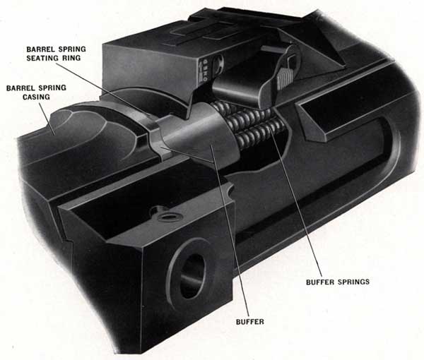
The casing for the barrel springs carries the recoiling end of these springs, Figure 43. A barrel spring front sleeve fits into the front end of the casing and is the front seat for the springs. A barrel spring center sleeve is the intermediate support for the barrel springs and is located between the two springs. It is a loose fit on the barrel. A barrel spring seating ring that is locked in the front end of the breech casing is the rear seat for the barrel springs. See Figure 46. The recoil buffer springs, described below, assist the barrel springs.
Figure 46-Recoil Buffer Springs
61
RECOIL BUFFER SPRINGS
A set of twelve buffer springs are mounted in the forward end of the breech casing, Figure 46.
These recoil buffer springs assist the barrel springs to absorb the recoil and also assist the breech block mass in counterrecoiling. They operate only during the last inch of recoil and during the first inch of counterrecoil. The total compression of the twelve buffer springs, plus the barrel springs at full metal to metal recoil, is 3084 pounds on the rectangular wire type and 2616 pounds on the round wire type barrel and buffer springs.
NOTE-The gun will continue firing with recoil buffer springs broken, but it is inadvisable to allow this except in action, as the recoil tends to become metal to metal. Parts are then liable to be damaged and THE GUN BECOMES LESS STEADY FOR LAYING AND THE RATE OF FIRE DROPS. See Maintenance Instructions Pages 112 and 113.
A recoil buffer, Figure 46, retains the buffer springs in the breech casing, and the rear end of the barrel spring casing contacts this buffer during the last inch of recoil, compressing the springs. The buffer is held in the breech casing by the barrel spring seating ring. See Figure 46.
TRIGGER BUFFER SPRINGS
One of the duties of the trigger group is to intercept the recoiling mechanism, in order to keep the gun cocked whenever the trigger is released during firing, and, as the recoiling mass is moving forward at high speed, there is a severe shock at the moment of interception. The trigger buffer springs cushion this shock, thereby protecting the sear and trigger hook.
There are fifteen trigger buffer springs (R), Figure 24, mounted in the trigger casing (C), Figure 24.
This trigger casing also carries the trigger hook and the trigger parallelogram levers, and is locked in the breech casing by the hand grip mounting piece. The trigger casing is free to move forward a short distance by compressing the trigger buffer springs against the breech casing. This cushions the interception of the recoiling mass.
62
63
64
MAGAZINE
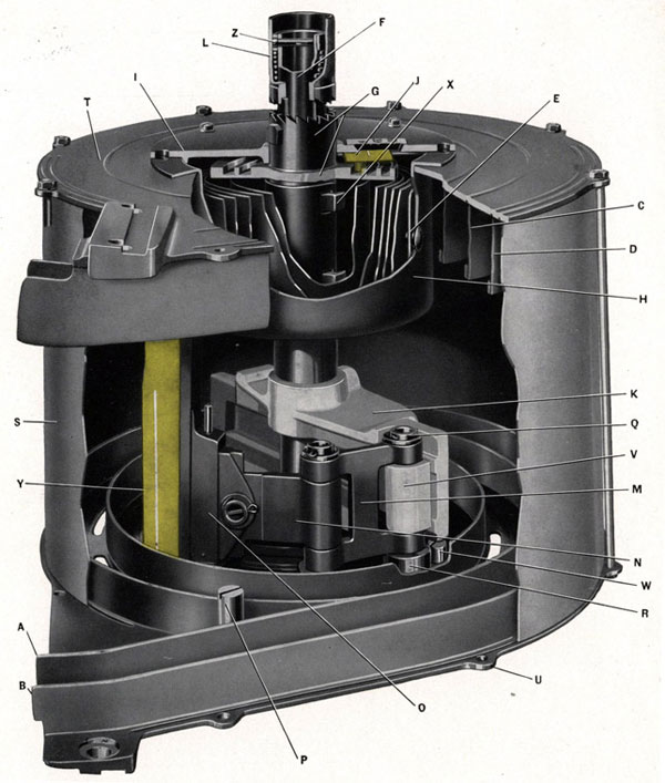
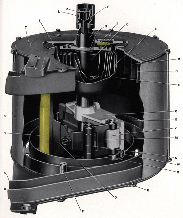
Figure 47-Magazine Internal Parts
65
MAGAZINE OPERATION
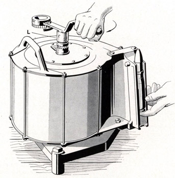
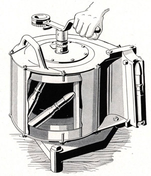
The magazine consists of a cylindrical drum containing 60 rounds of ammunition that are driven around spirals, see A, B, C and D, Figure 48, inside the drum, by a clock spring (E) that is hand wound from outside the magazine. The tension of the spring can be adjusted.
MAGAZINE FEED ACTION
The feed system maintains a pressure on the innermost round, by means of a wound clock spring (E), Figure 47, that is always endeavoring to push the rounds around the spirals (A, B, C and D), and out of the magazine mouthpiece. The lips of the magazine mouthpiece are partly closed so that a round can pass through it only by being pushed out longitudinally at a right angle to the direction of the feed drive, a gap being cut in the front, or muzzle end, of the mouthpiece to allow the rounds to slide in or out.
MAGAZINE SPRING
The pressure on the innermost round is from a clock spring (E), Figure 47, that is housed in the magazine casing. The outer end of the spring is held to a spring case by a securing pin at (E). The spring case is bolted to the magazine casing by screws, thus fixing the outer end of the magazine clock spring. The inner end of the spring is hooked on the spring axis (G) at point (X), and any tension on the spring (E) tends to turn this spring axis (G). This spring axis (G) can either rotate freely on the mainshaft (F), or can be coupled to it by a spring coupling sleeve (L) having ratchet teeth. When this coupling sleeve (L) is in engagement the tension of the clock spring (E) is transmitted to the main shaft (F) tending to rotate it.
MAGAZINE CARTRIDGE FEEDER
The feed block (K) driven by the main shaft carries the feed arm (V) which can slide through the feed block to the radius of any point in the spiral path (A, B, C and D). The cartridge feeder link (M) is pinned to the feed arm (V) and to the feed head (N) by two articulating bolts (Q). These two articulating bolts have rollers (R) that guide the feed system around the spiral. The cartridge feeder (O) swivels on the feed head (N) pushing the cartridge (Y) around the spiral.
MAGAZINE SPRING TENSION LIMITS
The spring axis (G) has a spiral groove cut on its flange, and this spiral groove actuates an indicator block (J), Figure 47, that slides in a radial direction in the cover plate (I). This block (J) is an indicator of the amount of tension in the spring (E), and it also stops the winding or unwinding of the spring when the end of the spring axis spiral groove is reached.
NOTE-This block (I) does NOT indicate how many rounds of ammunition are in the magazine, but shows the amount of tension in the magazine clock spring (E). THE ZERO POSITION OF THE INDICATOR BLOCK (J) SHOWS THAT IT HAS REACHED THE END OF THE SPRING AXIS GROOVE AND IS HOLDING WHATEVER TENSION
N-Feed head (OE-1563)
O-Cartridge feeder (OE-1567)
P-Stop bolt-long (OE-1576)
Q-Articulating bolt (OE-1564)
R-Articulating bolt roller (OE-1565)
S-Casing (OE-1544)
T-Front plate (OE-1537)
U-Rear plate (OE-1538)
V-Feeder arm (OE-1561)
W-Stop bolt-short (OE-1577)
X-Lugs where spring fastens to spring axis
Y-Cartridge
Z-Ratchet cross pin (OE-1587)
66
REMAINS IN THE CLOCK SPRING (E). IN THIS POSITION THE RATCHET TEETH OF THE COUPLING SLEEVE (L) CAN BE DISENGAGED FROM THE MAIN SHAFT (F) THUS FREEING IT FROM ALL SPRING DRIVE.
The last round of ammunition should be fed into the magazine mouthpiece just before the indicator block (J) reaches the end of the spring axis groove.
NOTE-The amount of residual tension in the magazine spring is of importance as it indicates how much drive will be imparted to feeding the last round.
Instructions for checking and adjusting the magazine spring tension are given on Page 71.
LOADING THE MAGAZINE
NOTE-The last two rounds loaded in each magazine should have blind loaded projectiles. This practice is generally adopted to obviate the danger of firing of an H. E. projectile through the muzzle cover.
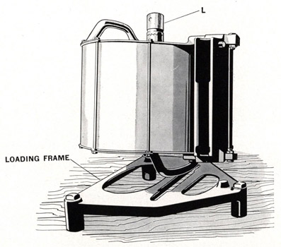
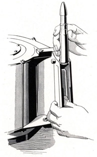
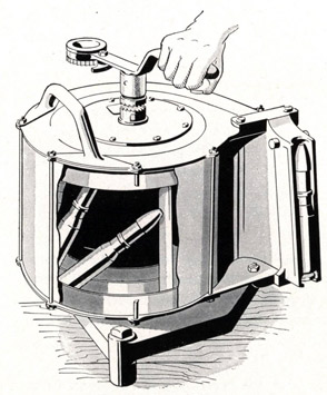
1. Place magazine in the loading frame (OE-1591) as shown in Figure 48.
NOTE-See if the indicator block is at zero, and if it is not, the spring tension must be relieved as instructed on Page 72.
Figure 48-Placing magazine in loading
frame, coupling (L) down
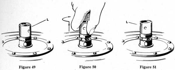
2. Pull out the coupling sleeve (L), Figure 50, as far as possible, and while holding it out, turn it to a point where, when released, it is on the lugs of the main shaft and will not snap down and engage the ratchet teeth again, Figure 51. Turning the coupling sleeve about an eighth turn, should hold it disengaged.
67
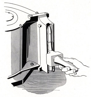
3. Place the loading lever on the end of the main shaft, as shown in Figure 52. This will permit the feed axis to be revolved and thereby rotate the cartridge feeder.
4. Revolve the loading lever clockwise, until the cartridge feeder is in the magazine mouth.
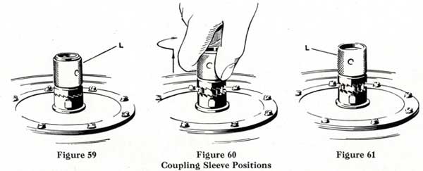
COUPLING SLEEVE POSITIONS
5. Remove loading lever from coupling sleeve, leaving the coupling sleeve (L) in its pulled out position, as in Figure 51.
6. Push, by hand, through the magazine opening against the cartridge feeder, and move it back just
Figure 52-Magazine loading lever on
main shaft (feed axis)
68
far enough to leave space for the insertion of one or two cartridges. NEVER LEAVE SPACE FOR MORE THAN TWO CARTRIDGES.
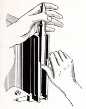
7. After a cartridge is inserted, press by hand against it, moving it back far enough to insert one or two cartridges. See Figure 53. Continue inserting cartridges until the magazine is full. Capacity of magazine is 60 cartridges.
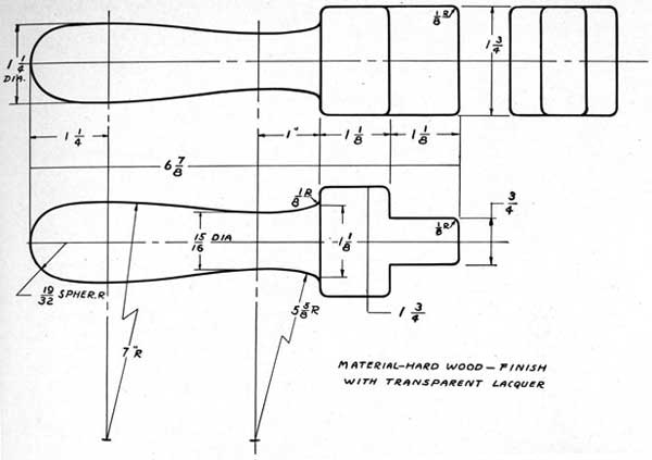
Instead of pressing the cartridge by hand, magazine loading tool (299712-7), illustrated in Figure 54, can be used to better advantage.
Figure 53-Hold feeder back just far enough to insert one cartridge
Figure 54-Loading the magazine with loading tool (299712-7)
If desired, it can be made on shipboard by cutting it out of a piece of hardwood to the dimensions shown in Figure 55.
69
Figure 55-Drawing of loading
tool (299712-2)
Magazine loading tool assembly (367524), illustrated in Figure 56, will be found helpful in rapidly loading cartridges into the magazine. To use the tool, clamp it over the mouthpiece of the magazine. Pull the handle backward and feed the cartridges into the mouthpiece, one at a time. As the cartridge is placed in position, push the handle forward and then pull backward. Repeat the operation until the magazine is loaded.
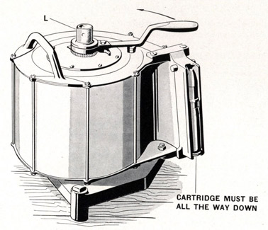
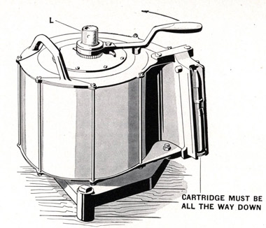
NOTE-It is essential that all cartridges be pushed all the way down to the bottom of the magazine mouth so that their bases are in alignment and firmly seated on the magazine rear plate, as shown in Figure 58. This is important because the breech block moves very rapidly and the magazine must feed the cartridge to it properly, so that the face piece can readily pick up the cartridge.
CAUTION-Great care should be taken not to push the cartridges and feeder a further distance than is necessary for the insertion of TWO cartridges. If the cartridges with the cartridge feeder are pushed in too far, they might become upset, and jam. A jammed magazine can be caused by pushing the feeder back too far by hand, or by using the
70
Figure 56-Loading the Magazine with
loading tool assembly (367524)
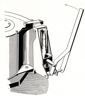
Figure 57-Magazine jammed because the
cartridge feeder has been pushed back too
far by the loading lever on the feed axis
loading lever on the feed axis, as shown in Figure 57. IF THIS HAPPENS IT IS NECESSARY TO DISMANTLE THE MAGAZINE TO CLEAR THE JAM.
It is sometimes impossible to push by hand a number of cartridges back into the magazine in order to make room for more, and this is particularly true toward the end of the loading of the magazine. When this condition occurs, use the loading lever as shown in Figure 52. Rotate the loading lever counter-clockwise very slightly for a distance necessary for the insertion of one or NEVER OVER TWO cartridges.
CAUTION-IF THE LOADING LEVER IS ROTATED FARTHER THAN THIS, THE CARTRIDGES WOULD HAVE ROOM TO FALL INTO AN OBLIQUE POSITION, SEE FIGURE 57, THEREBY PREVENTING FURTHER LOADING, AND MAKING IT NECESSARY TO DISMANTLE THE MAGAZINE AND CLEAR THE JAM.
8. When the magazine has been correctly filled to capacity (60 rounds), the coupling sleeve must be revolved by hand until it drops into engagement with the ratchet teeth as shown in Figure 49.
NOTE-THE MAGAZINE CLOCK SPRING MUST THEN BE EITHER COMPLETELY, OR SLIGHTLY, TENSIONED AS INSTRUCTED IN THE FOLLOWING:
COMPLETELY TENSIONING A MAGAZINE SPRING.
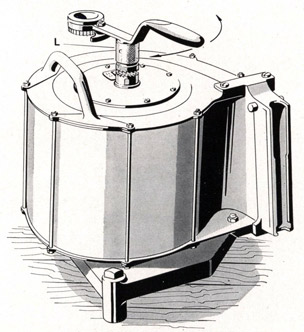
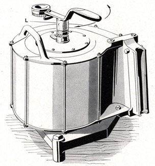
9. When the loaded magazine is to be used immediately, the spring is tensioned completely in the loading frame. Place the loading lever on the spring axis, as shown in Figure 58. Revolve the loading lever counterclockwise. Continue revolving the loading lever until a stop becomes distinctly noticeable. This indicates that the clock spring is completely tensioned. Remove the loading lever. Remove the loaded magazine from the loading frame and install on a gun.
71
DO NOT STORE A FULLY TENSIONED MAGAZINE, BECAUSE OF THE UNNECESSARY STRAIN ON THE WOUND CLOCK SPRING.
Figure 58-Tensioning the Magazine Spring
SPRING TENSION INDICATOR
The indicator scale on the front cover of the magazine shows "0," "15," "30," "45" and "60" and these figures are a measure of the magazine spring tension. Magazines are given either a partial spring tensioning when being stored for future use, or a complete tensioning when being used immediately. The amount of spring tensioning will depend upon how many cartridges there are in the magazine, as for example, a load of 30 or 45 cartridges requires a different spring tension than a full load of 60 rounds.
Partial tensioning of a magazine for storage purposes requires only a slight spring pressure, and the number of cartridges in the magazine makes no difference.
In the case of a magazine completely filled to its capacity of 60 rounds, and fully tensioned, the indicator will read "60."
In case the magazine has a partial load of cartridges, then the spring is tensioned according to the load in the following manner: There are openings in the back plate of the magazine through which the rear ends of the cartridges are visible. Tension the spring for ten more cartridges than there are in the magazine.
NOTE-Hold the coupling sleeve (L), Figure 58, with the fingers to prevent its turning when tensioning the spring on a partly loaded magazine. If it is permitted to turn, the cartridge feeder will be backed away from the cartridges and a jam may result.
SLIGHT INITIAL TENSIONING OF A MAGAZINE SPRING
10. When a fully or partly filled magazine is to be stored, the spring is given a slight initial tensioning that is just sufficient to hold the cartridges upright.
72
NOTE-A slight tensioning with the loading lever in the position shown in Figure 58 is sufficient. If the magazine is fully loaded or only partly filled, this slight initial tensioning is necessary to prevent a jam in the magazine.
11. If no initial tensioning is given the magazine spring, the cartridges are liable to fall out, become disarranged, or be tipped over when the magazine is lifted from the loading frame.
RELIEVING THE MAGAZINE SPRING TENSION
It may become necessary to relieve the spring tension on the magazine feed block to unload, to store, or to strip the magazine.
RELIEVING MAGAZINE SPRING TENSION
1. Place the magazine in the loading frame in the same manner as when loading. See Figure 48. Place loading lever in the spring tensioning axis as shown in Figure 63.
NOTE-The loading lever will not clear the magazine handle, so place it in such a position that it has room to move clockwise from one side of the handle to the other.
2. The tension of the spring causes pressure on the ratchet teeth of coupling sleeve shown in Figures 59, 60 and 61. Therefore, press counter-clockwise on the loading lever to relieve this pressure, and at the same time disengage the coupling sleeve with the other hand by pulling outward, Figure 60, and turning about one-eighth turn, so that the sleeve stays disengaged. See Figure 61.
3. Allow the loading lever to move clockwise, as far as it can (until it contacts the magazine handle). Turn the coupling sleeve slightly and allow it to snap down and mesh the ratchet teeth. See Figure 59.
4. Press on the loading lever ratchet pawl and revolve the loading lever back to position from which it started in Step 1. Then release the pawl.
5. Repeat Step 3, until the spring tension is completely relieved and no pressure can be felt against the lever.
NOTE-If the cartridges are to be left in the magazine, the spring must be given a slight initial tension before taking the magazine out of the loading frame in order to prevent their falling out, or being tipped over, Figure 57.
73
Figure 62-Unloading a fully tensioned magazine
UNLOADING A FULLY TENSIONED AND COMPLETELY FILLED MAGAZINE
If a magazine is loaded with cartridges and has been fully spring tensioned, and it is desired to unload the cartridges and relieve the tension of the magazine clock spring; it can be done by pushing the cartridges out, one by one, as shown in Figure 62. This action removes the cartridges and relieves the spring tension at the same time. It is not necessary to use the loading lever or disconnect the coupling sleeve.
UNLOADING A COMPLETELY FILLED MAGAZINE HAVING INITIAL SPRING TENSIONING ONLY
It is advisable to relieve the initial spring tension completely and this is done by using Steps 1, 2, 3 and 4, Page 72, these being the same as for "Relieving Magazine Spring Tension." In this case of initial tensioning, the loading lever will relieve the slight initial tensioning in the first 4 Steps,
and Step 5 will be unnecessary. Place the loading lever as in Figure 63 and revolve it clockwise with one hand, so that a cartridge is constantly being pressed against the magazine mouthpiece. Use the other hand, and push out the cartridges as they appear at the mouthpiece.
NOTE-The loading lever must be made to revolve continuously as the cartridges are being removed, or the cartridges will upset and jam. IF THIS HAPPENS IT IS NECESSARY TO DISMANTLE THE MAGAZINE TO CLEAR THE JAM.
UNLOADING A FULLY TENSIONED AND PARTLY FILLED MAGAZINE
It is advisable to relieve the spring tension by using Steps 1, 2, 3, 4 and 5, Page 72, and then unload the cartridges as instructed above. See Figure 63.
Figure 63-Unloading a partly tensioned magazine
74
STRIPPING THE MAGAZINE
STRIPPING THE MAGAZINE
NOTE-The magazine should be stripped by an artificer.
1. Place magazine in loading frame.
2. Empty the magazine of cartridges unless the stripping is being done to eliminate a jam, in which case it will be necessary to proceed with cartridges still in the magazine.
3. There are eight screws that hold the cover plate (I), Figure 64, on the magazine. Remove six of these, leaving any two that are directly opposite each other, in place.
4. Install the loading lever on the spring axis as shown in Figure 66, and relieve spring pressure as instructed on Page 72, Steps 2, 3, 4 and 5.
N-Feed head (OE-1563)
O-Cartridge feeder (OE-1567)
P-Stop bolt-long (OE-1576)
Q-Articulating bolt (OE-1564)
R-Articulating bolt roller (OE-1565)
S-Casing (OE-1544)
T-Front plate (OE-1537)
U-Rear plate (OE-1538)
V-Feeder arm (OE-1561)
W-Stop bolt-short (OE-1577)
X-Lugs where spring fastens to spring axis
Y-Cartridge
Z-Ratchet cross pin (OE-1587)
75
Figure 65-Magazine
76
5. With coupling sleeve disengaged, Figure 61, place the loading lever on the feed axis, Figure 66, and revolve it counter-clockwise, until the cartridge feeder (O), Figure 65, is at the inner end of its travel.
6. Turn the coupling sleeve so that it snaps down and engages the ratchet teeth, Figure 59.
7. Install the loading lever on the magazine spring axis as shown in Figure 67. Turn the loading lever counter-clockwise just far enough to take the slight remaining spring tension.
8. Hold the loading lever in the position described in Step 7, and remove the two remaining screws from the cover plate (I), Figure 65. Keep the loading lever in the position given in Step 7, and loosen the cover plate (I) from the magazine with a screw driver or suitable tool, being very careful not to pry up the spring casing flange.
NOTE-The loosening of the cover plate with a screw driver frees it from the spring casing, and now the remaining spring tension may be allowed to rotate the loading lever clockwise.
9. All spring tension is now eased off and the loading lever can be unshipped.
10. Rotate the spring housing assembly until one of the holes in the coupling sleeve is in line with the head of ratchet cross pin (Z), Figure 65.
11. Lift spring case (H) containing spring (E) accompanied by the spring axis (G) until its flange clears the dowel screw in the front plate (T), and turn it until the letters "D" in the front plate (T) and cover plate (I) are in line. As the spring and case are supplied as an assembly under part number (299709) it is not necessary to remove the spring from the case. If either part is damaged, replace with the new assembly. Remove the spring axis (G) by twisting it in the spring to disengage lugs (X) from the holes in the spring.
12. Remove the snap ring from the rear end of the main shaft (F), using pliers (OE-1608) in tool roll.
13. Remove the complete main shaft (F), feed block (K), feeder link (M) and cartridge feeder (O) from the front.
14. The feeder link (M), feed block (K), and cartridge feeder (O) can be separated by removing the bolt cotter pins and tapping out the two articulating bolts (Q), and feeder swivel bolt, using (OE-1613) punch in tool roll.
15. The magazine casing (S) should not normally be stripped into its component parts.
Figure 66-Magazine loading lever on main shaft (feed axis)
77
REASSEMBLING THE MAGAZINE
Figure 67-Loading lever on spring axis
REASSEMBLING
Thoroughly lubricate all parts. See Magazine Maintenance on Page 78.
1. Assemble the main shaft (F), feed block (K), feeder arm (V), feeder link (M), two articulating bolts (Q) with their rollers (R), feed head (N), bolt washers, bolt cotter pins and cartridge feeder (O).
2. Lubricate, see Page 78, and insert this feed group assembly into the magazine from the front.
Engage the rollers (R) in the spiral guideway (A) and (B). Insert the rear end of the main shaft into its bearing in the rear plate.
3. Assemble the snap ring at the rear end of the main shaft. To check the action, turn the feed system so that the cartridge feeder (O) is outward at the limit of its travel in the empty position.
4. Pack the spring and case assembly with grease (OS-1350). Insert spring axis (G) in spring (E) and engage lugs (X) in the two holes in the center turn of the spring. Insert this assembly into the magazine with the letters "D" in line. Rotate the spring case until the dowel hole marked "0" in its flange, engages the dowel screw in the front plate of the magazine.
NOTE-Examine the spring case holes that are counter-clockwise from the hole marked "0." In a few cases they may be marked "1," "2," "3," and up. If these markings are found, then turn the spring case (H) so that the hole with the highest number, instead of the hole marked "0," is engaged with the dowel screw on the front plate of the magazine.
5. Place the cover plate (I) on the magazine, and do not install any screws in it. Move the indicator block (J) with a knife blade, or any similar tool, so that it engages in the spiral groove on the spring axis (G), Figure 65.
NOTE-Up to this point it is permissible to have the cover plate (I) in any position ; also the indicator block (J) can be engaged in the spiral groove of the spring axis (G) in any position.
78
6. Turn the cover plate (I) counter-clockwise until the indicator shows zero and the indicator block (J) can be felt coming up against the clock spring (E).
7. Assemble the coupling sleeve (L) with its spring, the retaining ring and the cross pin.
8. Ship the loading lever on the spring axis (G) as shown in Figure 67 and turn the loading lever counter-clockwise about seven-eighths of a revolution or until the letter "A," stamped on the cover, is in alignment with letter "A" stamped on the magazine casing.
9. Maintain this position by holding the loading lever, and install the eight cover screws.
CAUTION-The counter-clockwise rotation of the cover from the zero position in Step 6 to "A" alignment in Step 8, has to be done against the clockwise pull of the clock spring. Approximately seven-eighths' revolution of the cover by the loading lever, should bring the alignment marks "A" opposite each other. BE VERY CAREFUL NOT TO TURN MORE THAN THIS AMOUNT. ALSO, DO NOT ALIGN MARKS "A" BY TURNING THE LOADING LEVER CLOCKWISE.
CHANGING MAGAZINES
It is essential that the magazine loader be adept in changing magazines. The proper procedure is as follows:
(a) Grasp the magazine front handle with the right hand and cock the magazine catch by pushing forward on the lever with the left hand.
(b) With the right hand, tilt the magazine slightly with the forward end down, grasp the magazine rear handle with the left hand and remove the magazine from the gun.
(c) Tilt the loaded magazine slightly with the forward end down and the forward guide lugs slipped all the way forward flush against the magazine receiving slot.
(d) Next, the rear of the magazine is put smartly into place with a sharp downward motion.
(e) Check to see that magazine is firmly locked in place by shaking with the handles. If locked there will be no motion of magazine.
MAGAZINE MAINTENANCE
CORRODED OR DRY MAGAZINE
If a magazine becomes dry or corroded internally, it must be disassembled, cleaned, and lubricated with grease (OS-1350). See instructions for disassembling and reassembling magazine, Page 74.
MAGAZINE CLOCK SPRING
The magazine clock spring was packed with grease, when the magazine was issued. However, this grease tends to squeeze out in service. Watch this spring for evidences of corrosion, and if corrosion is found, clean and repack with grease (OS-1350).
MAGAZINE INTERLOCK BOLT
The spring that is behind the magazine interlock bolt may become corroded, or may operate slowly, due to the use of too thick an oil, or because the oil thickens in cold weather. This magazine interlock bolt is the part on magazine cartridge feeder that causes the gun to be held in a cocked position when the magazine has fed its last round to the gun. See Page 48 for detail description. Therefore, any corrosion or slow operation
79
MAGAZINE MAINTENANCE
due to thick or thickened oil, will cause the gun to fail to remain in a cocked position after firing the last round of each magazine.
Use grease (OS-1350), and apply sparingly and often.
GENERAL LUBRICATION OF MAGAZINE
All moving parts should be lightly coated with grease (OS-1350). A light coat of the same grease should be applied to the spiral guideways in the magazine.