Insert this addendum in O.P. 911 and write the
following on the cover: "Addendum 1 entered."
ORDNANCE PAMPHLET NO. 911
Addendum 1 July 12, 1944
20 MM A.A. GUN
20 mm Machine Gun Mechanisms, Marks 2 and 4
20 mm Gun Barrels, Marks 2, 3, 4, and 4 Mod. 1
20 mm Sights, Marks 2, 4, 4 Mod. 1, and 5
20 mm Magazines, Marks 2 and 4
20 mm Shoulder Rests, Marks 2, 4, 5, and 5 Mod. 1
O.P. 911 is changed as follows:
The purpose of this addendum is to amplify the instructions contained in O.P. 911, and to describe new tools and methods intended to increase the efficiency and safety of operation of the 20 mm A.A. gun. The following items are covered herein:
(a) Breech Face Piece Tool
(b) Auxiliary Handle for Magazine
(c) Magazine Casualty
(d) Cocking Index Line
(e) Plugging of Holes in Shield Plates
(f) Parallelogram Assembly
(g) Permanent Set of Barrel Springs
(h) Safety Handles for Ejector Rod Assembly
(i) Spring for Barrel Bore Inspection Mirror
(j) Hammer Plate Securing Spring
(k) Breech Face Piece
(l) Cotter Pins for Trigger and Barrel Locking Lever
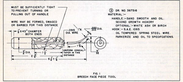
(a) BREECH FACE PIECE TOOL
Figure 1 has been approved for production and will be furnished in the tool rolls of new guns. For guns now in service, the tool of Figure 1 may be made up by any activity that considers it desirable. A number of similar tools have been submitted by the Fleet. In one case, a common file handle was used as a grip for the tool. In another design, one end of a rod was pointed in a manner similar to that shown in Figure 1 and the other end was formed into a loop to serve as an integral handle. Any of these methods may be employed, provided that the pointed end of the tool conforms generally to that shown in Figure 1.
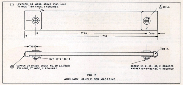
(b) AUXILIARY HANDLE FOR MAGAZINE
Difficulties have been encountered in removing 20 mm magazines from Type X ready service stowage chests similar to NYD Norfolk Sk. No. 47237 (BuOrd. Dr. No. 332979) - 20 mm Ready Service Ammunition Chest. In this type of chest, the magazines are racked with their axes horizontal, and the handles are not readily accessible through the opening at the top of the chest.
- 2 -
Figure 2 shows an auxiliary handle that has been developed to aid in lifting magazines from chests of this type. The handle is fastened to the magazine by the two casing bolts which are on top when the Magazine is stowed. The handle is not available for distribution to the service but may be manufactured and used by any activity that so desires.
(c) MAGAZINE CASUALTY
A casualty has occurred in service wherein a cartridge in the magazine mouthpiece was fired while the magazine was being shipped. The forward guide lugs on the magazine were not pushed all the way forward and the rear part of the mouthpiece struck and tripped the magazine catch (299679-2), allowing the ejector (299681-1) to move forward. The toe of the interlock lever (299680-4) then struck the primer of the cartridge in the mouthpiece, igniting the propellant. In order to prevent a recurrence of this casualty, care should be taken shipping a magazine to see that the guide lugs are pushed all the way forward in the slot in the breech casing before the rear of the magazine is lowered into place.
(d) COCKING INDEX LINE
Occasionally the need arises for some visible indication of whether or not the gun is cocked. In one instance, following a stoppage, the breechblock was retracted to a point where it was supposedly cocked and the safe-fire lever was turned to the "safe" position. The block, however, was actually being held in the retracted position by the cartridge case which had jammed between the block and the breech casing. When one of the personnel, thinking that the mechanism was latched back, partially released the case with his hand, the recoiling mass suddenly moved forward and a serious injury resulted. To prevent a similar occurrence, it is recommended that an index line be painted on one of the breech bars and on the breech casing in such a manner that if the recoiling parts are retracted to the point where the two lines match up, the block will latch back. The recoiling parts should travel about 9/16" beyond the final latched back position in order that the breech pawls may properly engage the lugs on the bottom parallelogram levers. This point can be determined by drawing back the recoiling mass slowly and listening for the click as the pawls pass under the lugs.
(e) PLUGGING OF HOLES IN SHIELD PLATES
Accomplishment of Ordalt No. 1395, by which the shields on 20 mm Mounts, Marks 2 and 4 are lowered to increase the sight field, leaves four unused 17/32 inch diameter holes in each shield plate. It has been suggested that these holes be plugged to prevent the possible passage of small fragments or bullets. It is recommended that, if it is desired to plug the holes, l/2" bolts (12-Z-24-82), nuts (12-Z-9-5) and lockwashers (12-Z-22-55) be used.
(f) PARALLELOGRAM ASSEMBLY
Damage to the breech pawls, parallelogram levers and trigger crank may result from improper installation of the new type, parallelogram axis bolt, top front (299695-6). When reassembling parallelogram mechanisms having this type of bolt, the head of the bolt must always be installed on the right hand side (looking toward the muzzle). The letter "R" is marked on the head of the axis bolt, and when the bolt is correctly assembled the letter will be visible from the right side. Some of the first of this type of bolt, however, were issued without the letter "R" on the head.
(g) PERMANENT SET OF BARREL SPRINGS
In Ordnance Pamphlet No. 813, 20 mm A.A. Gun and Mount, Mark 4 and Mark 2, it is stated that whenever possible the gun should be kept uncooked in order to relieve the spring tension and prevent the possibility of a permanent set of the barrel springs. This statement also appears in the new Ordnance Pamphlet on the 20 mm A.A. Gun, O.P. 911, which supersedes O.P. 813. However, information now at hand, based on the results of tests conducted by the Naval Gun Factory, indicates that holding the mechanism in the retracted position over long periods of time has a negligible effect upon the life of the barrel springs. It is therefore, considered a satisfactory practice, from the standpoint of barrel spring life, to keep the gun cocked during any period of readiness which the occasion demands.
- 3 -
(h) SAFETY HANDLES FOR EJECTOR ROD ASSEMBLY
The backing out of a projectile from the barrel by means of the ejector rod assembly supplied with the tool roll entails a certain amount of risk. In one instance, a member of a 20 mm A.A. gun crew received serious injuries when, in attempting to back out a projectile, the nose of the projectile was struck with sufficient force to explode the fuze and detonate the burster charge. Even when the ejector tool is applied gently, there is the possibility, in the case of a hot barrel, of the round "cooking off" during the process of removal. In order to lessen the danger to the operating personnel, a new ejector tool is under design, and will consist essentially of a central rod with handles projecting outward and rearward on each side. Using the projecting handles, the operator can keep his hands and arms out of the line of fire of the gun, in the event that the round should detonate. Until such time as the new tool is in production and becomes generally available, it is recommended that all the activities using the 20 mm A.A. gun install auxiliary handles on the present cleaning rod and ejector assembly. A suggested arrangement is to secure (either by welding or by means of an adapter) a U-shape steel bar to the cleaning rod handle assembly (299816-l or 367516-1) in such a manner that, when the ejector rod is inserted in the barrel, the ends of the bar will project toward the rear and be in the same plane as the barrel bore axis
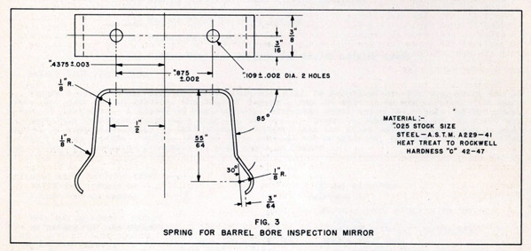
(i) SPRING FOR BARREL BORE INSPECTION MIRROR
A new design of barrel bore inspection mirror has recently been approved for production. The new mirror assembly differs from the present design (367517) in that the mirror and its supporting arm can be folded back into the frame to facilitate stowage, and the sides of the frame fit snugly (with spring action) in the magazine slot in the breech casing. Until such time as the new type of mirror assembly becomes available, the bore inspection mirrors now on hand may be altered to provide a retaining spring for securing the mirror assembly to the casing. Figure 3 shows the details of a spring which is intended to be fastened to the under side of the present bore inspection mirror base (367517-2 or 3) by means of rivets. The spring should be located so that the rivets are about 59/64" from the rear of the base. Authorization is given for the manufacture and installation of the spring by any service activity that considers it desirable.
(j) HAMMER PLATE SECURING SPRING
It is considered that some cases of hammer breakage can be attributed to improper seating of the hammer plate (299677-2) rather than to any defect in the hammer itself. If the hammer plate securing spring (299677-1) has been weakened during assembly or disassembly or if it has not been properly seated in its slot in the breech casing, it is possible for the hammer plate to work over into such a position that one of the front toes of the hammer will strike the camming surface intended for the rear toe, resulting in breakage of the hammer. Accordingly, it is recommended that special care be taken during assembly to insure that the securing spring is properly seated in the slot in the breech casing. Regular and frequent inspection of the hammer plate and spring should be made, and if the spring is found to be weak it should be replaced. If the spring is bent out of shape, it should be straightened, or if necessary, replaced.
(k) BREECH FACE PIECE
Peening of the forward end of the striker pin hole in the breech face piece (299651-1) some times occurs and interferes with the operation of the striker pin (299653-1) and hammer (299654-l). The face piece should be inspected frequently and, when any evidence of peening is discovered, the striker pin hole should be cleared out to its original diameter.
- 4 -
(l) COTTER PINS FOR TRIGGER AND BARREL LOCKING LEVER
It has been reported that the securing pins (299672-6) used on the trigger (299698-3) and the barrel locking lever (299672-1) are, at first, difficult to remove, and, after several assembly operations, often become loose and drop out. To eliminate this condition it is recommended that the securing pins be replaced with 1/8" x 1" split cotter pins (12-Z-48-38 or 638). In some cases the existing holes may be too small to admit the cotter pins, and should be enlarged by means of a 1/8" drill. Attention is called to the fact that the trigger is hardened to Rockwell "C" 47-53, and special care must be taken in drilling this part. When installing the cotter pin in the trigger, it should always be inserted from the rear in order to prevent the possibility of the split ends jamming between the trigger and the trigger cover.
1. Insert enclosure (A) in subject Ordnance Pamphlet and write on cover, "Addendum 2 entered."
(Enclosure A)
ADDENDUM 2 to OP 911.
OP 911 is changed as follows:
PAGE 86 : Add this sheet as page 86a.
A small quantity of pentolite loaded 20-mm. ammunition was manufactured in this country for Lend Lease and in a few instances was issued to US vessels. HEI-T, tetryl loaded, 20-mm. has never been placed in production. However, the above rounds are included in the color chart to permit identification in event any of these types are issued to US vessels from British sources.
DISTRIBUTION:
Standard Navy Distribution List No. 15, 2 copies each unless otherwise noted.
1. a-h, j-n, q_u, w, x, z-ff, ii-ll, nn, oo, qq-zz ; 2. a, d-j, 1-p, r, s, v, aa, dd ; 3. c, d, e, g, j, k, 1, m*, n, o, p*, r, s, t, u, v, w*, x-z, aa*, bb-ee, ff*, gg, hh, ii*, jj, kk, ll, mm, nn*, oo*, pp*, qq-vv, ww*, xx-aaa, bbb*, ccc*, ddd-fff ; 3. (5 copies), a, f; B3. CONSTRUCTION BATTALIONS; B3. (5 copies, LIONS, CUBS, ACORNS) ; 4, b, c, d, e, g, i-1, m*, o, p, r-yy;4. (5 copies) , a, f; 5. b (Alusna, London only), e; 6. a-p ; 7. f-i, x, y; 7. (5 copies), b, p; 7. (10 copies) , a; 8. h (NOL and No. Beach only) , i, j, n (SPECIAL LIST K, L, R, S, V, X, Z, AA) , r, u, v, x, z; 10. s, t; 11. a (BuDocks, Vice CNO, SecNav, ComdtMarCorps); 12; 14; a; OCO, War Dept; Auxiliary Proofing Range.
*Applicable Ships.
Requests for this publication should be addressed to the nearest BuOrd Publications Distribution Center: Comdt and Supt, NavGun, NYd, Wash. 25, D. C.; Comdt, NYd, Mare Island, Calif.; OinC, OrdPubSubcen, NSD, Pearl; ComSerFor, Seventh Fleet, OrdPubSubcen, c/o FPO, San Fran.