The following description covers the barrel and its breech casing with the various stops and locking devices mounted on it.
Figure 8-Barrel Locking Gear
TRIGGER MECHANISM
The trigger mechanism is mounted in a casing of its own and is described on Pages 39 to 53.
RECOILING MECHANISM
Recoiling Mechanism is covered in detail on Pages 57 to 61.
GUN BARREL NOMENCLATURE
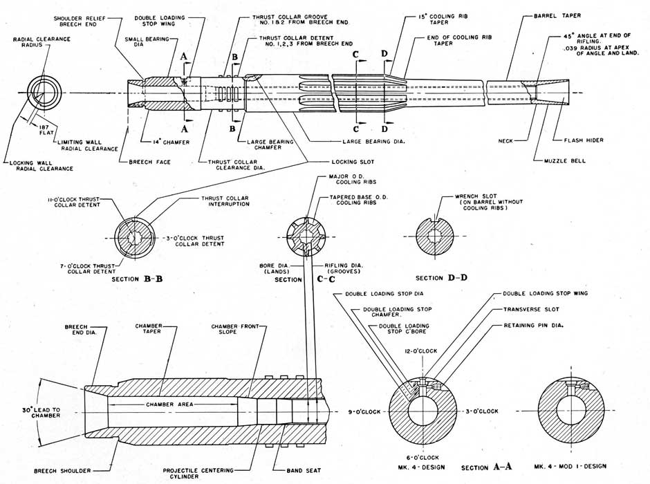
To provide a standard by which the various sections and make-up of the barrel of the 20 mm. A.A. Gun may be described in correspondence or discussion the proper nomenclature is illustrated in Figure 9.
A similar drawing has been given wide distribution among the various agencies and personnel dealing with this subject so that a clearer picture in the discussion of this part may obtain.
24
Figure 9-Gun Barrel Nomenclature
25
GUN BARREL
The gun barrel, Figure 9, is a forged steel piece 4 feet 9 11/64 inches long, bored out to a caliber of ".7898 or approximately 20 mm. In the rifled section of the bore there are nine grooves with a right hand twist of one turn in a length of 36 calibers.
The following types of gun barrels have been issued to the service, all of which are interchangeable in either Mark 2 or Mark 4 Machine Gun Mechanisms:
Barrel Designation
Cooling Ribs
Stop Plunger-Lower
Mark 2
Yes
Keyhole Head
Mark 3
Optional
Keyhole Head
Mark 4
Optional
Keyhole Head
Mark 4 Mod. 1
Optional
Round Head
Some Mark 4 gun barrels without cooling ribs were issued to service labeled Mark 4 Mod. 1.
The first two inches of the barrel, known as the muzzle bell, has a flare which serves as a flasher
hider.
GUN BARREL REPLACEMENT
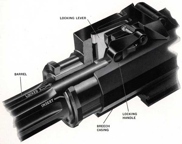
The gun barrel is provided with three interrupted thrust collar detents located near the rear end, which engage in three corresponding grooves in the breech casing, see Figure 10, and lock the barrel in place. The barrel is further prevented from rotating in the breech casing and accidently unlocking by the "Barrel Locking Gear" described on Page 26.
The barrel can be easily removed and a new one installed without stripping of any other parts.
Figure 10-Gun Barrel ready for installation
26
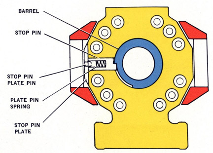
BARREL STOP PIN
A stop pin is assembled in the left side of the breech casing and engages, in an external slot in the rear end of the barrel. See Figure 11.
When inserting the barrel and rotating it into place, the stop pin positions the barrel so that the locking lever can be engaged in its slot in the barrel by moving the handle to the position marked "Locked".
This stop pin also serves to limit the rotation of the barrel in the opposite direction, so that the thrust collar detents are clear of the grooves in the breech casing and permit withdrawal of the barrel.
Figure 11-Barrel Stop Pin
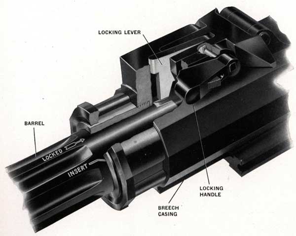
BARREL LOCKING GEAR
The barrel locking gear (shown in Figure 12 and Section J-J of gun assembly Plate 1) consists of three parts:
1. Barrel locking handle pinned to-
2. An axis bolt (upon which the double loading stop is free to rotate).
3. Barrel locking lever, attached to the axis bolt.
The purpose of the barrel locking gear is to prevent the barrel from rotating and thereby freeing itself from the interrupted thrust collars, during the firing of the gun.
The barrel locking handle carries a catch lever that moves a plunger, holding the barrel locking handle in either of two positions, "LOCKED" or "UNLOCKED." When the catch lever is pressed in toward the breech casing and the handle is moved from "UNLOCKED" to "LOCKED", the axis bolt is turned, thereby rotating the barrel locking lever into a slot in the barrel. This locks the barrel so that it cannot rotate about its own axis.
DOUBLE LOADING STOP
The double loading stop prevents loading a round of ammunition into the barrel unless the chamber
27
is already clear at the double loading stop lower plunger. This plunger operates in a hole in the top wall of the chamber of the barrel. The operation of the double loading stop is illustrated and described more completely on page 34.
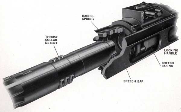
BREECH CASING
The breech casing, Figure 12, is a steel forging, bored out longitudinally and its principal functions are to:
1. Carry the barrel at its front end.
2. Carry the trigger group at its rear end.
3. Act as a guideway for the reciprocating breech block.
4. Carry the magazine on its top.
5. Attach to the mount.
Figure 12-Gun Barrel installed ready to be locked in breech casing
28
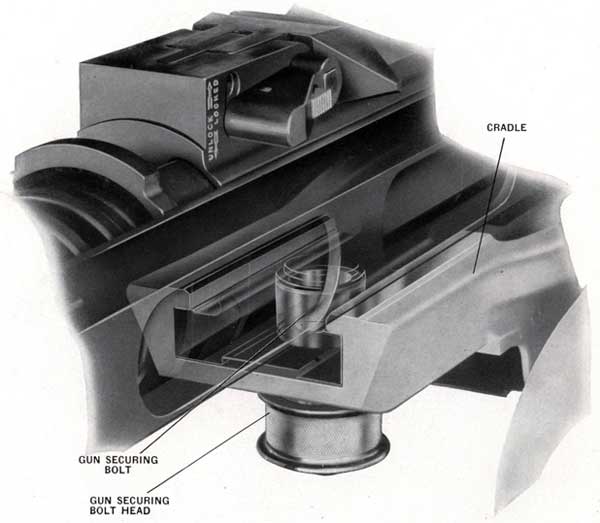
GUN MOUNTING ATTACHMENTS
The gun is secured to the cradle of the mount by:
1. Two shoes that are a part of the breech casing (located at the front and rear) and fit into keyways in the cradle, Figure 13.
2. A gun securing bolt in the cradle which enters into a corresponding recess in the front shoe of the casing and takes the main fore and aft thrust on firing, Figure 13.
Figure 13-Gun Mounting Attachments
29
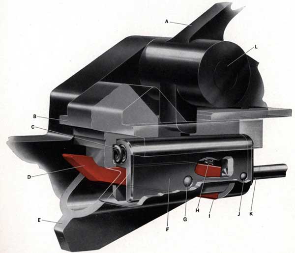
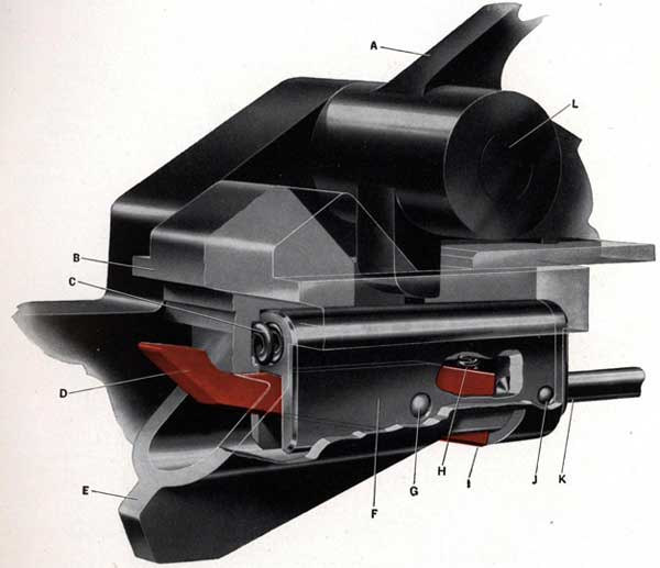
MAGAZINE CATCH GEAR AND EJECTOR
Magazine Catch Gear and Ejector, Figure 14, is mounted in the breech casing and consists of three sections:
1. Catch gear to retain the magazine in position.
2. Ejector.
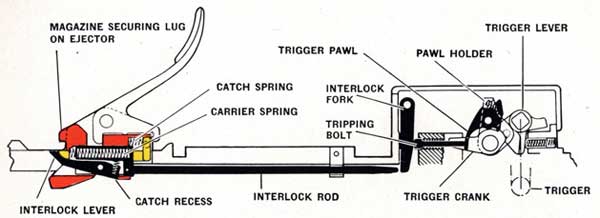
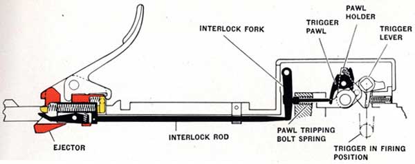
3. Front portion of the magazine interlock gear, as shown in Figure 14. See Page 48 for details of trigger gear operation caused by interlock rod.
Figure 14-Magazine Interlock Gear in firing position
A-Magazine catch lever (OE-1043)
B-Magazine securing lug on ejector
C-Interlock carrier spring (OE-1340)
D-Interlock lever (OE-1074)
E-Ejector (OE-1045)
F-Interlock carrier (OE-1066)
G-Axis bolt (OE-1067) holding interlock lever to interlock carrier
H-Magazine interlock lever spring (OE-1330)
I-Magazine interlock lever in catch recess in ejector
J-Axis pin (OE-1261) holding interlock rod to interlock carrier
K-Interlock rod (OE-1075)
L-Magazine catch lever spring axis bolt (OE-1076)
30
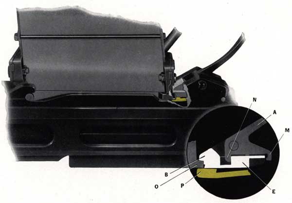
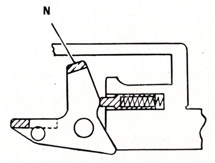
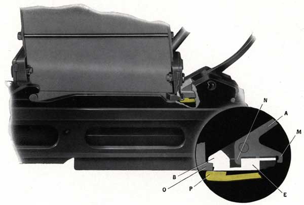
The magazine catch gear is operated by a magazine catch lever (A), Figure 14, rotating on an axis bolt (L) mounted on the breech casing. The front toe (N), Figure 15, on the lever engages with a face on the ejector (E). The rear toe (M) on this lever engages with the upper rear end of the ejector. The ejector (E) is free to move slightly in a longitudinal direction and, therefore, can be moved rearward by rotating the magazine catch lever (A) toward the muzzle.
Figure 15-Magazine in shipped or firing position, showing catch
down and ejector locking magazine in place
A-Magazine catch lever (OE-1043)
B-Securing lug on ejector for magazine
E-Ejector (OE-1045)
M-Rear toe of magazine catch lever
N-Front toe of magazine catch lever
O-Lug on magazine for locking by ejector
P-Magazine catch (OE-1046)
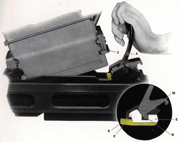
The ejector normally tends to move forward because of the pressure of the magazine catch spring, Figure 16. However, the ejector can be held cocked to the rear by the magazine catch (P), Figure 18. The magazine catch is pivoted at the rear and is able to rise in front. The magazine catch spring in addition to forcing the ejector forward, tends to force the catch into engagement with the front end of the ejector, as shown in Figure 18.
On the front end at the top of the ejector is a lug (B), Figure 15, that engages a corresponding lug (O) on the magazine and holds the magazine to the gun. See Figure 15. If the ejector is held cocked to the rear by the catch, the lug is clear of the magazine so that the latter can be shipped or unshipped. See Figures 17 and 18. As above mentioned, the ejector can be moved rearward to the cocked position by rotating the magazine catch lever toward the muzzle.
31
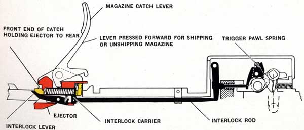
Figure 16-Magazine interlock gear in firing position
When the magazine is shipped, the ejector is moved forward automatically into position for locking the magazine. A projection on the magazine pushes down the front ends of the catch, disengaging it and allowing the ejector to move forward under the influence of the catch spring, into position to lock the magazine.
The catch may be disengaged without the necessity of shipping a magazine by pressing down the forward ends of the catch, using any suitable tool. The forward ends of the catch are visible in Figure 18.
CAUTION-When shipping a magazine the catch gear must be in the cocked position. The cocked position is shown in Figure 18, the magazine securing lug on the ejector being back of the front end of the catch. NO ATTEMPT SHOULD BE MADE TO COCK THE GEAR BY FORCING A MAGAZINE PAST THE LUG.
Figure 17-Magazine catch gear and ejector in position for
shipping or unshipping magazine
32
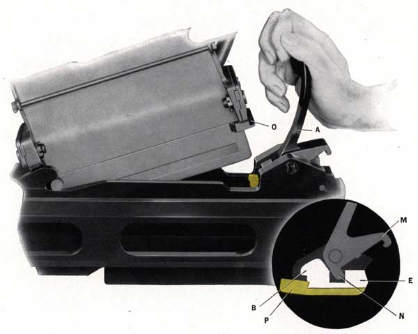
Figure 18-Unshipping a magazine-ejector moved to rear by hand
pressure on catch lever and held to rear by catch
A-Magazine catch lever (OE-1043)
B-Securing lug on ejector for magazine
E-Ejector (OE-1045)
M-Rear toe of magazine catch lever
N-Front toe of magazine catch lever
O-Lug on magazine for locking by ejector
P-Magazine catch (OE-1046)
EJECTOR AND CARTRIDGE EJECTION
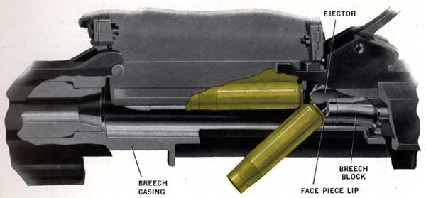
The ejector serves as a magazine catch as described in "Magazine Catch Gear and Ejector," page 29, and also performs its main function of ejecting fired cartridge cases by means of its front lower toe. See Figure 19. This toe engages in a groove in the top of the breech block and this groove is continued through the breech block face piece.
The breech block recoils to the rear, carrying a fired case in the lip of the face piece and, as it passes the ejector, the rear of the case strikes against the toe of the ejector. The fired case is thus tipped forward, also downward as shown in Figure 19 and is forced out of the lip of the face piece. This action occurs with a violence sufficient to eject the empty cartridge case down and through an opening cut in the bottom of the casing.
33
Figure 19-Ejecting Fired Cases
NOTE-It is of vital importance to the functioning of the gun, that the recoiling mass move rearward with enough speed to clear the gun of the fired case. A sufficiently hard blow from the toe of the ejector must be delivered on recoil, to force the fired case clear of the casing before the breech block has commenced to counterrecoil. THE BOLT SHOULD NORMALLY RECOIL TO A POSITION WHERE THE FACE IS APPROXIMATELY 2.1 INCHES TO THE REAR OF THE FACE OF THE TOE OF THE EJECTOR. The fired cartridge case has to get clear of the gun casing during the period the breech block is to the rear of the ejector.
Any factor tending to reduce the recoil, such as friction, tight extraction, etc., will also cause sluggish ejection, and this must be avoided, because of the possibility of a fired cartridge case failing to clear the counterrecoil of the breech block and causing a jam. The most common stoppage met with in this type of gun is caused by the sluggish ejection described above, with the fired case jammed between the breech block and the chamber face.
To reduce sluggish ejection the cartridges are supplied lightly greased, in their boxes. Care should be taken to see that this grease is maintained and replaced, if necessary. A COAT OF MINERAL GREASE SHOULD BE ON EACH CARTRIDGE SO AS TO BE PERCEPTIBLE TO THE FINGERS. A LITTLE MINERAL GREASE APPLIED TO THE CARTRIDGE CASE, VISIBLE IN THE MOUTHPIECE OF A FILLED MAGAZINE SHORTLY BEFORE FIRING, IS ADVANTAGEOUS. OIL IS NOT TO BE USED AS A SUBSTITUTE FOR MINERAL GREASE.
MAGAZINE INTERLOCK GEAR OPERATION
The front end of this gear is carried in the ejector and the rear portion operates in conjunction with the trigger gear. The purpose of the magazine interlock gear is to stop the gun in a cocked position after the last round of each magazine is loaded into the gun, irrespective of the position of the trigger. Otherwise the breech block mass would counterrecoil on an empty gun, making it necessary to recock by hand before firing could be continued with a freshly loaded magazine. THE ACTION OF THE MAGAZINE INTERLOCK GEAR IS DESCRIBED AND ILLUSTRATED ON PAGES 48 TO 53.
34
HAMMER PLATE OPERATION
This component is being described here, rather than in the Striker Gear section, because it is secured to the casing. See Figure 45. The Striker Gear group is carried by the breech block and is, therefore, a part of the recoiling group. This hammer plate is secured to the casing by dovetails and is locked by the hammer plate securing spring. It has two cam surfaces that actuate the hammer and thereby the striker pin. THE ACTION OF THE STRIKER GEAR IS DESCRIBED AND ILLUSTRATED ON PAGE 58.
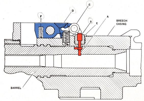
DOUBLE LOADING STOP OPERATION
The purpose of the double loading stop gear is to make it impossible for the breech block to counter-recoil and load a round into the firing chamber unless the chamber is already empty. This avoids the jam that would occur if the rear end of a cartridge case had been torn away, leaving a portion of the case jammed in the firing chamber.
Figure 20-Double loading stop gear. Gun is in cocked position
with stop plunger protruding into the firing chamber
The double loading stop (D) with its operating lever (C), upper plunger (B) and lower plunger (A) are shown in Figure 20 in the position they occupy when the gun is cocked. The double loading stop plunger (A) is projecting into the chamber and is the end actuated by the cartridge case. This lower plunger (A) lifts the upper plunger (B) against the rear toe of the double loading stop operating lever (C) lowering its front end ; this action permits the double loading stop to rotate about its axis under the pressure of its springs (F). The double loading stop (D) acts as a catch to hold the bolt mass to the rear.
35
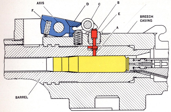
Figure 21-Double Loading Stop Gear. Gun has fired and cartridge is in firing chamber
The position of these parts when a cartridge is in the firing chamber is shown in Figure 21. The front end of the double loading stop (D) is raised by spring (F) and the rear end has fallen until it is in the path of the stop plates mounted one on each breech bar.
NOTE-The positions of the lower plunger (A), upper plunger (B) and lever (C) remain the same in Figures 21, 22 and 23. The cartridge case is assumed to have ripped apart in Figures 21 and 22 with the part remaining, still holding lower plunger (A) flush against the firing chamber wall. The double loading stop (D) remains free to rotate, to a limited extent.
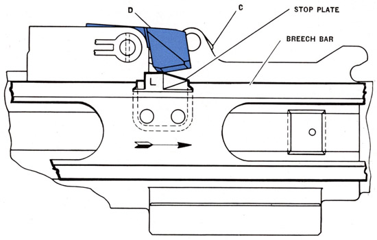
The left breech bar is shown, see Figure 22, recoiling to the rear carrying with it the stop plate marked "L". (On the right breech bar the stop plate is marked "R".) The rear end of the stop plates is sloped to lift the double loading stop (D), Figure 22, against the pressure of its springs. The springs assert themselves after the hardened stop plates have passed the double loading stop. See Figure 21. Faces on the rear end of the double loading stop (D) then intercept the hardened stop plates on the breech bars as the breech bars counterrecoil and thereby hold the entire recoiling mass to the rear as shown in Figure 23.
When the gun is operating normally the fired cartridge case is ejected before the breech bars have recoiled far enough to reach the double loading stop (D), Figures 22 and 20. When ejection of the fired cartridge case occurs, the double loading stop lower plunger (A) is no longer held outward by the cartridge case and the whole system is then returned to its inward position by the spring under the double loading stop lever (C).
36
Figure 22-Double Loading Stop Gear. Part of cartridge
shell left in chamber as recoil takes place
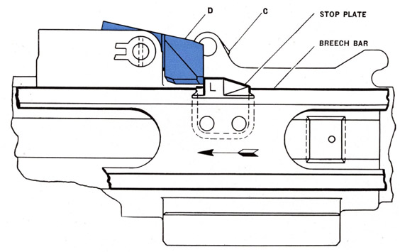
Figure 23-Double Loading Stop Gear. Counterrecoil is arrested by
the stop plate bearing against the double loading stop
C-Double loading stop lever (OE-1053)
D-Double loading stop (OE-1054)
37
Interception of the breech bars by the stop plates on breech bars intercepting the double loading stop (D) occurs only if a portion of the fired cartridge case remains in the chamber in line with plunger (A).
The double loading stop lower plunger (A) is shaped to lie flush with the curve of the firing chamber wall. This lower plunger (A) has a shoulder on its outer end that prevents it from turning and also limits the travel of the lower plunger. The upper plunger (B) is limited on its inward travel by a shoulder on the guide bushing (E) and on its outward travel by the rear end of operating lever (C), Figures 20 and 21.
A new style double loading stop plunger-lower is used in the Mark 4 Mod. 1 gun barrel (OE-1013). This plunger (OE-1014), differs from the former part, (OE-1011), in that it has a round head and its lower end is flat instead of curved to the inside radius of the gun barrel chamber.
NOTE-THE DOUBLE LOADING STOP OPERATES IN THE EVENT OF A TORN CARTRIDGE CASE BEING LEFT IN THE CHAMBER AND IN CONTACT WITH THE LOWER PLUNGER, Figure 79. IF THE PORTION OF THE TORN CARTRIDGE CASE LEFT IN THE CHAMBER IS FORWARD OF THE STOP, THE DOUBLE LOADING STOP WILL NOT OPERATE AND A JAM WILL OCCUR.
38
39
TRIGGER MECHANISM
Chapter 4
The illustrations used in this chapter show the action of the parts diagrammatically in order to best explain their operation. The gun assembly drawing, Plate 1, shows all parts in their correct proportions.
L-Parallelogram lever plunger-top (OE-1213)
M-Parallelogram lever-rear (OE-1203)
N-Parallelogram lever-top (OE-1204)
Q-Parallelogram lever-bottom (OE-1206)
R-Trigger buffer springs (OE-1326)
S-Trigger (OE-1220)
T-Magazine interlock fork (OE-1230)
U-Magazine interlock rod (OE-1075)
V-Parallelogram lever-front (OE-1205)
W-Trigger hook spring (OE-1343)
X-Breech pawl (OE-1104)
40
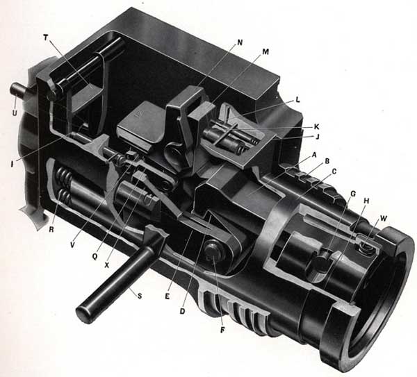
TRIGGER FUNCTION
The principal feature of the trigger group is that a trigger hook (A), Figure 24, mounted on the breech casing (B), (a non-recoiling part) can hook onto the recoiling sear (D) that is on the end of the breech bolt (E) and thereby hold the recoiling mass in the cocked position, Figure 24.
Additional features are:
(A). The trigger hook (A) can be kept in the released position by keeping the trigger pressed in order to allow automatic fire.
(B). The trigger hook automatically intercepts the recoil sear and holds the recoiling mass in the cocked position when the trigger is released or when the last round in the magazine has been fired, Figure 25. It is, therefore, unnecessary to recock by hand to resume firing or after changing magazines.
Figure 25-Recoiling mass being held in a cocked position
M-Parallelogram rear lever
N-Parallelogram top lever
Q-Parallelogram bottom levers
V-Parallelogram front lever
The recoiling mass is shown in Figures 24 and 25 held in the cocked position. The barrel springs are compressed and are tending to pull the breech block toward the muzzle (looking at Figures 24 and 25 this would be to the left). The recoil sear (D), Figure 24, is attached to the rear end of the breech bolt by an axis bolt (F).
The trigger hook (A) is hooked on the recoil sear (D), thereby preventing the breech block and its bolt (E) from moving forward. This trigger hook (A) is pivoted on an axis bolt (G) in the trigger hook holder (H). The trigger hook holder (H) rests in the trigger casing (C).
The trigger hook is always endeavoring to disengage from the recoil sear. This attempt to disengage is due to the action of two forces:
1. The spring (W) at the end of the trigger hook (A), Figure 24, is exerting pressure on the end of the trigger hook (A) to lift the opposite end from the recoil sear (D).
41
Figure 26-Trigger action on parallelogram
I-Trigger pawl tripping bolt (OE-1225)
M-Parallelogram lever-rear (OE-1203)
N-Parallelogram lever-top (OE-1204)
O-Point of contact between trigger intermediate lever and trigger pawl holder
P-Point of contact between trigger crank toe and parallelogram top lever
S-Trigger (OE-1220)
T-Magazine interlock fork (OE-1230)
U-Magazine interlock rod (OE-1075)
Y-Point of contact between trigger pawl and trigger crank
Z-Trigger retaining bolt (OE-1221)
AA-Trigger intermediate lever (OE-1218)
BB-Trigger pawl holder (OE-1219) shown in BLUE
CC-Trigger pawl (OE-1222) shown in RED
DD-Trigger crank (OE-1223) shown in YELLOW
EE-Trigger pawl spring (OE-1332)
42
2. There is an upward thrust on the trigger hook that is caused by the forward pull of the barrelspring acting on the inclined faces of the sear and trigger hook. This is illustrated in Figure 25.
NOTE-These faces, it will be noted, do not constitute an interlocking hook, but are at such an angle that the barrel spring pull on recoil sear tends to force the trigger hook upward and out of the engagement ; simultaneously the trigger hook spring is exerting its pressure on the trigger hook trying to disengage it from the recoil sear.
COCKED POSITION
In the cocked position, Figure 25, upward movement of the trigger hook is blocked by the lever (M). This lever forms the rear member of a parallelogram consisting of the following:
1. Parallelogram top lever (N), Figures 24 and 25.
2. Parallelogram front lever (V).
3. Parallelogram bottom levers (Q) (left and right).
4. Parallelogram rear lever (M).
The four corners of the parallelogram are formed by axis pins thus allowing the four levers to pivot on each other. The pin connecting the top and rear levers (N and M) is also mounted in the trigger casing, Figure 24.
As previously stated there is an upward thrust on the trigger hook that is caused by the forward pull of the barrel spring acting on the inclined faces of the sear and trigger as shown in Figure 25. This upward thrust combined with the pressure of the spring loaded parallelogram lever plunger, rear (K), Figure 24, tends to rotate parallelogram rear lever (M) counterclockwise and thus pull the bottom levers (Q) to the right. These bottom levers (Q), however, cannot go to the right because they are held to the left by the breech bolt pawls (X) bearing against the lugs, Figures 24 and 25, on the bottom levers (Q). There are two levers (Q) and they form the bottom levers of the parallelogram against which the right and left breech pawls (X), Figure 24, bear. These two breech pawls (X) are pivoted on the breech bolt (E), Figure 24. The full weight of compressed barrel springs on the breech bolt makes it impossible for the two levers (Q) to be pulled to the right and, therefore, prevents the trigger hook from disengaging.
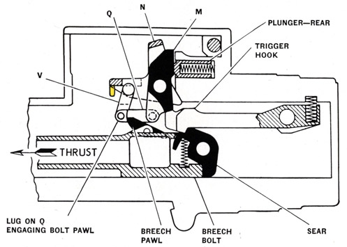
FIRING ACTION
Pressing the trigger will so move the parallelogram levers, Figure 29, that the trigger hook will be released from the recoil sear and the trigger hook will be kept clear of the path of the recoiling sear as long as the trigger is pressed or until the magazine is empty. The firing is entirely automatic.
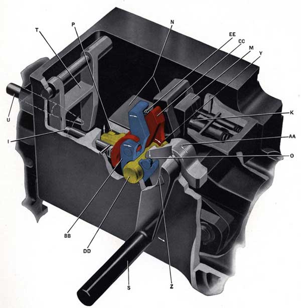
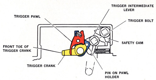
When firing, the pressing of the trigger (S) Figure 26, turns the trigger retaining bolt (Z) in a counterclockwise direction. The trigger intermediate lever (AA) is on the trigger retaining bolt (Z) and is also turned. A recess in this trigger intermediate lever (AA), Figure 26, engages a pin on the trigger pawl holder (Blue) and, as illustrated, this trigger pawl holder is made to turn on its axis in a clockwise rotation.
The trigger pawl holder (Blue), Figure 26, has an axis pin (also blue), and on it is placed the trigger pawl (Red). In between the pawl holder (Blue) and the pawl (Red) is a spring (EE) that is under compression in order to keep a toe on the pawl (Red) in engagement at point (Y) with a notch on the trigger crank (Yellow). As stated above, pressing the trigger turns the trigger bolt (Z), Figure 26, counter-clockwise; the trigger intermediate lever (AA), Figure 26, being on the same bolt is also turned counterclockwise; the recess (0) in the trigger intermediate lever (AA) turns the pawl holder (Blue) clockwise and carries the trigger pawl (Red) with it as a unit. As stated above, the toe of the trigger pawl is in engagement with the notch on the trigger crank and, therefore, when the trigger pawl is rotated clockwise the trigger crank also is rotated clockwise.
At the front end of the trigger crank (Yellow) is another toe that lies under a lip at point (P) of the parallelogram top lever (N). Movement of the trigger crank (Yellow) pushes up the front end of parallelogram top lever (N) causing it to rotate about its axis pin and forcing the parallelogram to slew into the position shown in Figure 28. Parallelogram bottom left and right levers (Q), Figure 28, are rotated about their axis on the parallelogram rear lever (M). The front end lugs (Q) of parallelogram bottom levers that
43
Figure 27-Trigger to trigger crank operation
Figure 28-Recoiling mass about to be released to fire the
gun, the parallelogram being moved by trigger crank
A-Parallelogram rear lever plunger spring
B-Trigger hook spring
M-Parallelogram rear lever
N-Parallelogram top lever
Q-Parallelogram bottom levers
V-Parallelogram front lever
FF is the point of contact between the parallelogram rear lever and trigger hook
44
were bearing against the breech pawls, Figure 28, are now disengaged. The attempt of the trigger hook to disengage itself from the recoil sear, is now about to be realized because the levers (Q) cannot restrain it, inasmuch as they are freed of the breech pawls and barrel spring. Levers (Q) can now go to the right, thus forcing lever (M) counterclockwise. Springs also assist in this action as follows:
Parallelogram Rear Lever Plunger Spring (A), Figure 28
Trigger Hook Spring (B)
The movement of the parallelogram rear lever (M) brings it into line with a recess in the trigger hook, allowing the trigger hook to rotate upward, about its axis and into the position shown in Figure 29 where it is clear of the recoil sear. This disengagement from the recoil sear releases the entire breech block mass so that it counterrecoils, under the push of the barrel spring, and fires the gun.
Figure 29-Recoiling mass released to fire the gun
M-Parallelogram rear lever
N-Parallelogram top lever
Q-Parallelogram bottom levers
V-Parallelogram front lever
The trigger pawl (Red), Figures 26 and 27, is on an axis pin in a trigger pawl holder (Blue). In between the pawl holder and the pawl is a spring (EE), Figure 26, that is under compression in order to keep a toe on the pawl (Red) in engagement at point (Y) with a notch on the trigger crank (Yellow). During the firing travel of the trigger pawl it remains in engagement with the trigger crank (Yellow).
This action retains the trigger gear in the position shown in Figure 29 as long as the trigger is kept pressed to the rear and there are cartridges in the magazine. In the position illustrated in Figure 29, the lugs on the parallelogram bottom levers (Q) are clear of the recoil and counterrecoil path of the breech pawls. The trigger hook is kept clear of the recoil sear by the trigger hook spring.
Releasing the trigger allows the trigger intermediate lever (AA), Figure 26, trigger pawl holder (Blue), trigger pawl (Red), and trigger crank (Yellow) to return to the position shown in Figure 26. The parallelogram top lever (N) is lowered by its plunger spring, Figure 30. This drops parallelogram front lever (V),
45
Figure 30-Action of spring plungers against parallelogram top lever
Figure 31, and parallelogram bottom right and left levers (Q) into such a position that the lugs on bottom levers (Q) lie in the recoil and counterrecoil path of the breech pawls.
On the breech block mass recoil the breech pawls ride under the bottom levers (Q), Figure 31, and, during the subsequent counterrecoil, engage them again as shown in Figure 31. The parallelogram lever (M) is still in the recess in the trigger hook as shown in Figures 29 and 31, and it is being kept in the recess by its spring. When the lugs on bottom levers (Q) are engaged by the breech pawls the effect is to pull the
Figure 31-Trigger released, recoiling mass about to start counterrecoil and be held in cocked position by breech pawls engaging parallelogram bottom lever lugs
M-Parallelogram rear lever
N-Parallelogram top lever
Q-Parallelogram bottom levers
V-Parallelogram front lever
46
bottom levers (Q) forward. This movement rotates the parallelogram rear lever (M) clockwise causing a face on it to press on the toe (FF), Figure 26, of the trigger hook forcing it down into engagement with the recoiling sear. The breech block mass is thus intercepted and held in the cocked position. See Figure 28, "Recoiling mass in cocked position."
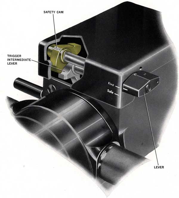
Figure 32-Safe/Fire Gear
47
SAFE/FIRE GEAR
A safe/fire lever is fitted close to the right hand-grip. When put to the "Safe" position it turns an axis bolt and rotates the safety cam.
The toe of the safety cam contacts the rear toe of the trigger intermediate lever thus locking it and preventing any movement. When put to the "Fire" position, Figure 32, the safety cam is rotated clear of the trigger intermediate lever.
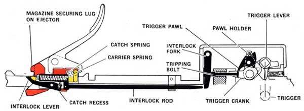
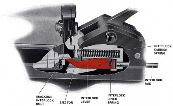
Figure 33-Magazine interlock gear in firing position
A-Magazine catch lever (OE-1043)
B-Magazine securing lug on ejector
C-Interlock carrier spring (OE-1340)
D-Interlock lever (OE-1074)
E-Ejector (OE-1045)
F-Interlock carrier (OE-1066)
G-Axis bolt (OE-1067) holding interlock lever to interlock carrier
H-Magazine interlock lever spring (OE-1330)
I-Magazine interlock lever in catch recess in ejector
J-Axis pin (OE-1261) holding interlock rod to interlock carrier
K-Interlock rod (OE-1075)
L-Magazine catch lever spring axis bolt (OE-1076)
48
MAGAZINE INTERLOCK GEAR
The purpose of the magazine interlock gear is to stop the gun in the cocked position after the last round of each magazine is loaded into the gun, regardless of the position of the trigger. Otherwise the breech block mass would counterrecoil on an empty gun, making it necessary to recock by hand before firing could be continued with a fresh magazine.
Figure 34-Magazine interlock gear in firing position
MAGAZINE INTERLOCK GEAR ACTION
The positions of the various parts of this gear, while the gun is firing, are shown in Figure 33. The
Figure 35-Magazine is empty-last round has been fired-interlock gear tripped by feeder bolt thus tripping trigger gear and keeping the gun cocked
49
Figure 36-Magazine interlock gear. Last round
has been fired. Trigger gear is now tripped
Figure 37-Interlock tripped, recoiling mass about to start counterrecoil and be held in cocked position by breech pawls engaging parallelogram bottom lever lugs
M-Parallelogram rear lever
N-Parallelogram top lever
Q-Parallelogram bottom levers
V-Parallelogram front lever
50
Figure 38-Recoiling mass held in a cocked position
M-Parallelogram rear lever
N-Parallelogram top lever
Q-Parallelogram bottom levers
V-Parallelogram front lever
Figure 39-Action of spring plungers on parallelogram top lever
front portion of the magazine interlock gear is shown in Figure 33. It should be noted that the interlock lever (D) is fastened by its axis bolt (G) to the interlock carrier (F) and the interlock rod (K) is also fastened to the interlock carrier (F) by pin (J). The interlock carrier spring (C) acts rearward on the carrier (F) when the lever (D) is out of its catch recess (I). The interlock lever spring (H) acts on the lever (D) tending to keep the lever in its catch recess (I) and the front end upward.
51
Figure 40-Unshipping a magazine-ejector moved to rear by
hand pressure on catch lever and held to rear by catch
A-Magazine catch lever (OE-1043)
B-Securing lug on ejector for magazine
E-Ejector (OE-1045)
M-Rear toe of magazine catch lever
N-Front toe of magazine catch lever
O-Lug on magazine for locking by ejector
P-Magazine catch (OE-1046)
The loading power of the magazine is by a clock spring behind the cartridge feeder in the magazine. This feeder operates against the last round in the magazine. A detail description and illustration of the magazine operation is given on pages 64 and 65.
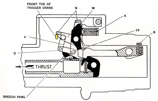
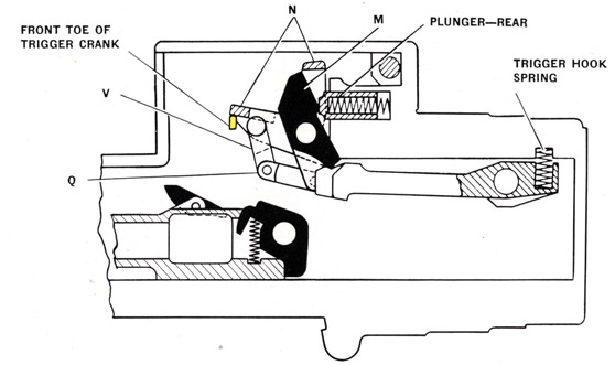
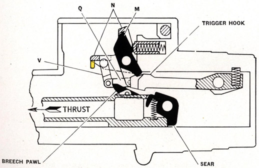
When the last round is fed into the gun, the cartridge feeder emerges at the mouth of the magazine, Figure 35. A bolt on the rear end of the cartridge feeder then bears down against the front end of the magazine interlock lever that is pivoted within the magazine interlock carrier and disengages it from the catch recess in the ejector. This leaves the magazine interlock carrier together with the magazine interlock lever free to move rearward within the ejector under the influence of the interlock carrier spring. As the carrier moves to the rear, it takes with it the magazine interlock rod. The rear end of the rod pushes against the magazine interlock fork, Figure 36, thus rotating the fork on its axis bolt. As the fork rotates, a part of
52
Figure 41-Magazine in shipped or firing position, showing
catch down and ejector locking magazine in place
A-Magazine catch lever (OE-1043)
B-Securing lug on ejector for magazine
E-Ejector (OE-1045)
M-Rear toe of magazine catch lever
N-Front toe of magazine catch lever
O-Lug on magazine for locking by ejector
P-Magazine catch (OE-1046)
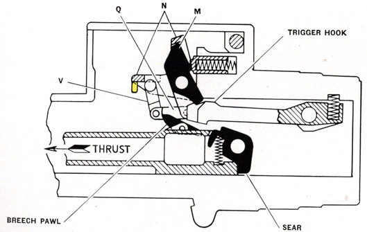
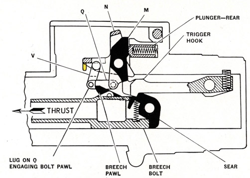
the fork presses against a bolt that bears in turn against the claw of the trigger pawl. The movement of this bolt then trips the trigger pawl disengaging it from the trigger crank permitting the trigger crank to drop. This lowers the front end of the parallelogram into the position shown in Figure 37. This brings the lug on the parallelogram bottom levers (Q) in line with the path of travel of the breech pawls on recoil and counter-recoil. As the breech block recoils the breech pawls slide under and past the lugs on parallelogram bottom levers (Q) and on the counterrecoil engage these lugs, and lock the trigger hook as shown in Figure 38.
MAGAZINE INTERLOCK WITHDRAWAL WHEN UNSHIPPING MAGAZINE
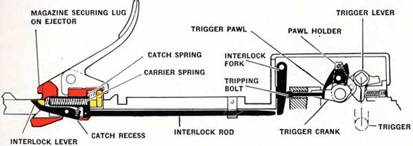
The action of moving the magazine catch lever toward the muzzle to free the empty magazine for unshipping, Figure 40, forces the ejector to the rear so that it overtakes the magazine interlock carrier. This allows the magazine interlock lever, pivoted within the magazine interlock carrier, to be forced by its spring into engagement again with the recess in the ejector thus locking the interlock carrier to the ejector once more. This movement of the ejector compresses the catch spring, Figure 42, moving the magazine catch about its pivot causing its front ends to contact the front end of the ejector thus holding the ejector in its rear position.
53
When shipping a new magazine a projection at the mouth presses down the forward ends of the catch, Figure 41, leaving the ejector free to move forward because of the pressure of magazine interlock catch spring, Figure 42, and lock the magazine to the gun as previously described under heading "Magazine Catch Gear and Ejector" page 29. In the course of this action of locking the magazine when the ejector moves forward the magazine interlock carrier is carried with it because it is engaged in the catch recess in the ejector, Figure 42, and the magazine interlock rod is also moved forward because it is fastened to the carrier. This forward movement of the magazine interlock rod frees it from the magazine interlock fork, Figure 42.
Figure 42-Magazine interlock gear in firing position
The magazine interlock fork and the trigger pawl tripping bolt then return to their original positions, Figure 42, because of the pressure of the trigger pawl tripping bolt spring, Figure 36. The trigger pawl, Figure 42, is thus left free to re-engage itself with the trigger crank because of the pressure of the compressed spring between the trigger pawl holder and trigger pawl.
NOTE-THE MAGAZINE IS HELD LOCKED TO THE GUN DURING THE PERIOD OF EJECTION OF THE CARTRIDGE. When the breech bolt mass is recoiling, the impact of the fired cartridge case against the ejector slides the ejector rearward into engagement with the recess (M), Figure 41, of the magazine catch lever thereby preventing it from rising. Thus the magazine is held locked to the gun during the period of the ejection of the cartridge.