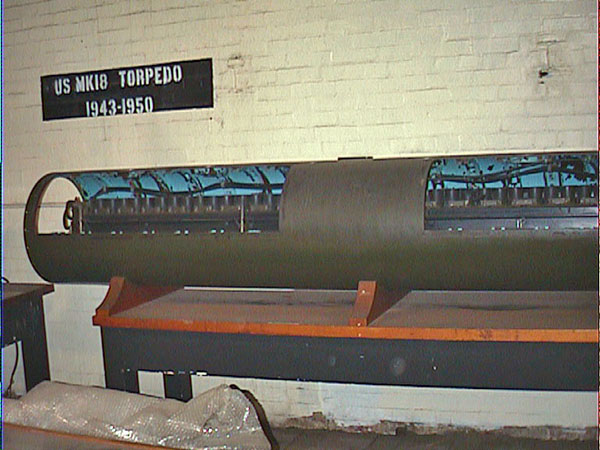
USS Pampanito Mark 18 Torpedo
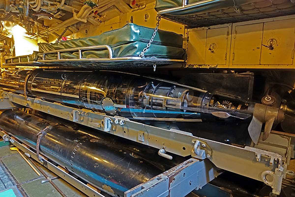
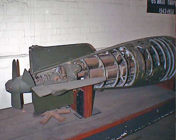
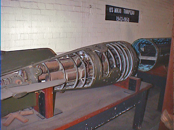
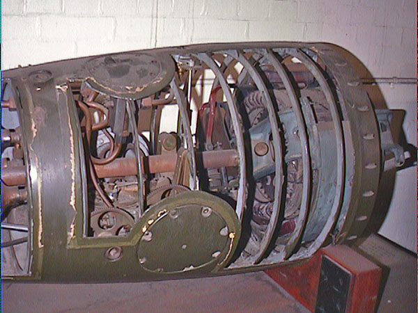
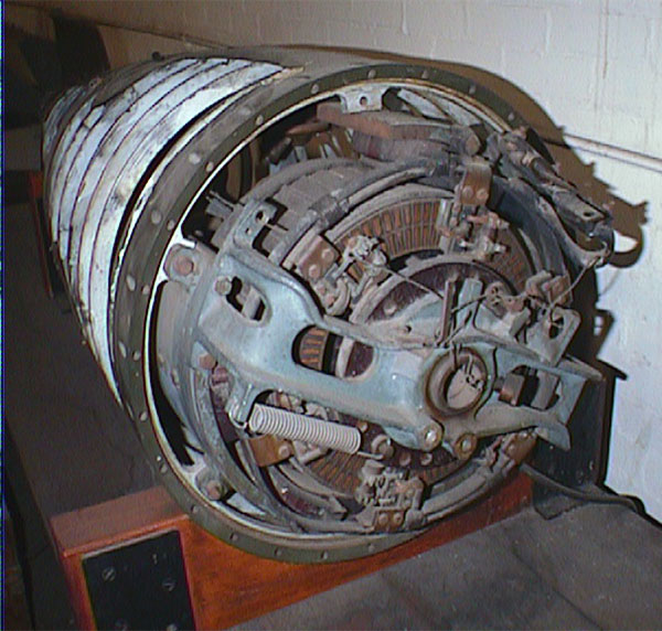
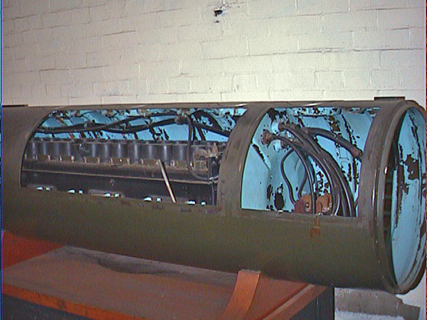
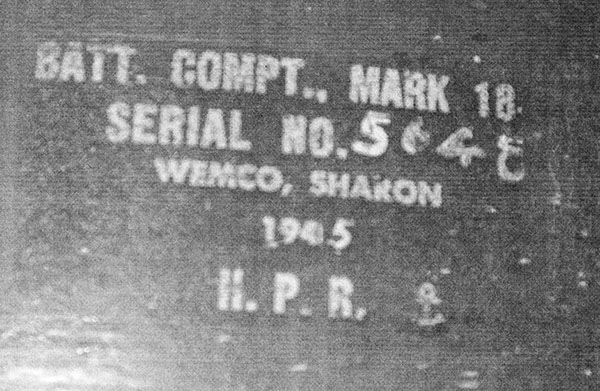
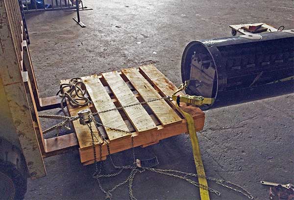
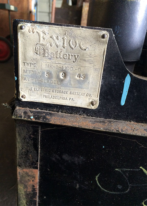
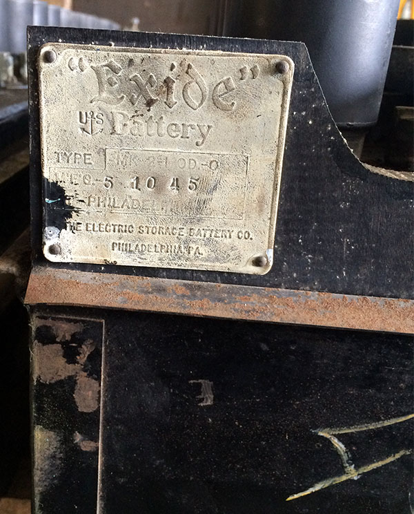
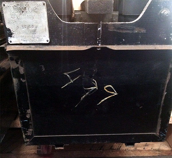
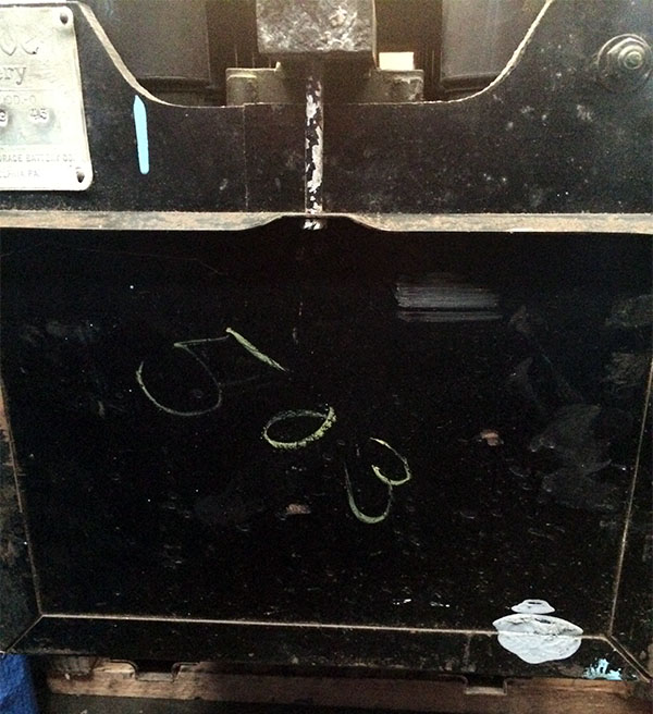
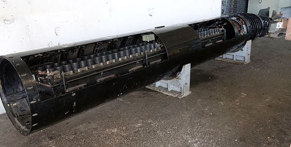
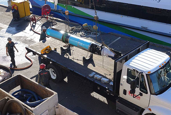
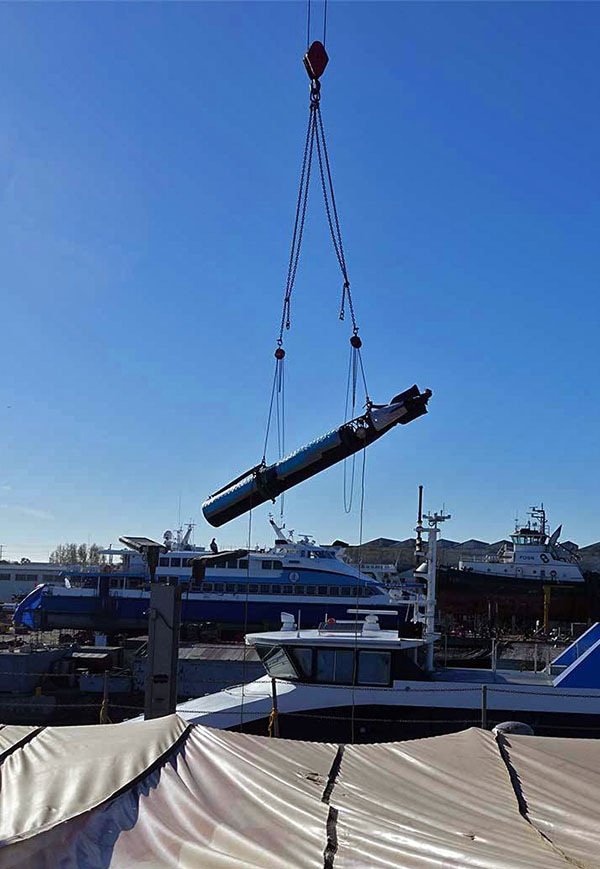
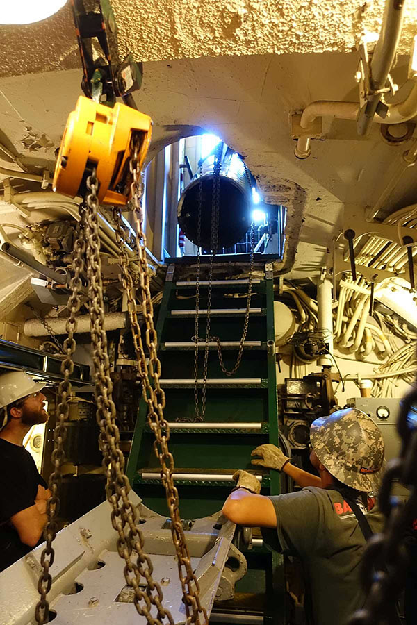
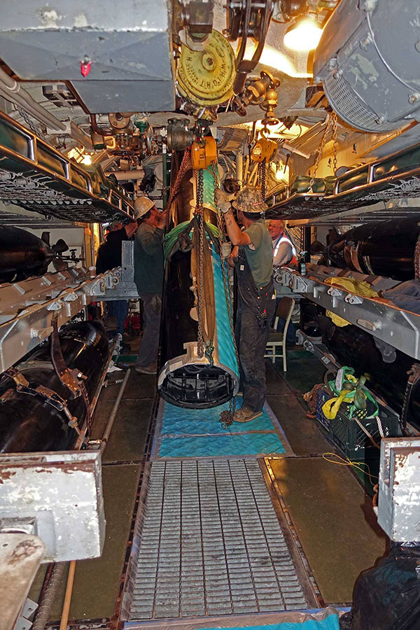
This note is a description of the project to display a Mk 18 Electric Torpedo on USS Pampanito, and a heartfelt thank you note to the individuals and corporations that helped make it possible. These are mostly working notes to document the changes made and to store the information needed to preserve the torpedo over time. We know from Pampanito's war patrol reports that she fired more Mk 18 electric torpedoes than Mk 14 steam torpedoes during the war. This was typical during 1944 and 1945. They were much simpler and cheaper to build than steam torpedoes and did not leave as big a wake trail of bubbles. They were also slower, shorter range, and less consistent in speed. When Pampanito became a museum in 1981 there was one Mk 14 torpedo aboard and the crew searched for a long time to find Mk 18s. It was difficult because very few of the Mk 18s were saved after they were withdrawn from service in 1950. We were successful finding eleven Mk 14s that are now aboard, and three on shore (Mk 14s were still in use in 1981.) However, it was not until 1999 that we were offered a training cut-away Mk 18 torpedo on loan from the Naval History and Heritage Command. The torpedo arrived with failed (non-historic) coatings, rust, missing parts, and was badly in need of stabilization and restoration. The 2006 Pampanito crew disassembled, painted the case, and partially reassembled the torpedo. The torpedo then waited for restoration and loading on Pampanito. During the 1960s the torpedo loading hatches, and the deck torpedo loading trays were removed when visitor stairs were added to the boat. This makes it much more difficult to load torpedoes than during WW II. In addition, this training torpedo had most of the structural frames cut with the shell that was cut to expose the inner workings of the torpedo. It still has the heavy batteries installed. This makes it more delicate than the Mk 14 torpedoes we have previously loaded on to Pampanito. No matter how good a rigger you are, anything loaded by a crane fixed to the earth will at some point need to mate with the moving boat and this can be unpredictable. However, in drydock the crane and the boat move together (and not very much) so it is much easier to load torpedoes while in drydock. Shortly before our 2016 drydocking we realized that if we could finish the stabilization of the torpedo and add visitor proofing we might be able to load during the drydocking. Very quickly the torpedo was prepared, and it was successfully loaded during Nov 2016. Data Plate Information:
Torpedo Mark 18 Mod 3, Registry 16366. NHHC 96-149-C Manuals Online:
U.S. Navy Torpedo Mark 18 (Electric), OP 946, 1943, is a basic service manual for the original (Mark 0) version. We have a Mark 3 torpedo so it is close, but different.
- Naval Undersea Museum Keyport sent us photos of their Mk 18 Mod 3 cut-away on display and loaned us their Mk 18 manuals for scanning. We also scanned the manuals in the Pampanito collection: - Battery Installation:
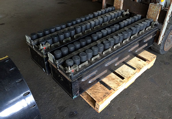
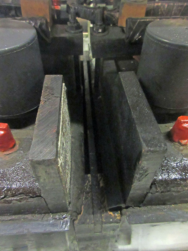
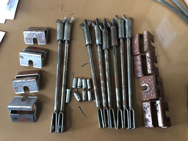
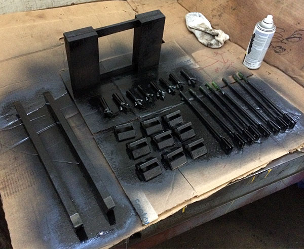
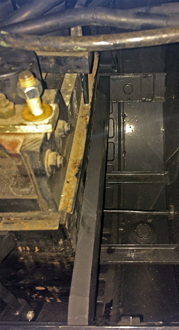
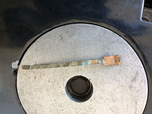
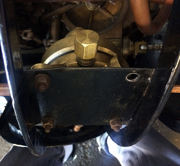
Replicated x2 extended wing nuts 3/8"-16 in stainless, bought x1 3/8" clevis pin, cotter pins. We looked for the missing battery braces and spacer in the restoration container, collections container, documents container, collections storage room, restoration working storage room, after&forward battery, dry stores, radio stores, small arms magazine without success. Curator does not think they can be in the library, documents storage or her office. We need to check above the offices, and warehouse. We replicated and installed temporary replacements for the missing forward battery brace (with two holes for jacks screws), jack screws, lock nuts, after battery brace, and between battery spacer. The Mark 2 battery is 1,236 lbs with acid, they are dry now so we guess they are 1,000 lbs. it would be dangerous to move the torpedo without these in place. NUM has a Mod 3 torpedo with original braces that could be documented as a basis for more accurate braces if we cannot find our originals. Note that when we find the original pieces, or create more accurate replicas we should be able to move the batteries enough to install them while on the boat in the torpedo loading tray (until we get a warhead installed.)
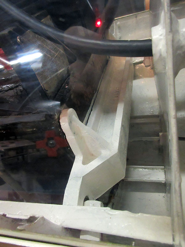
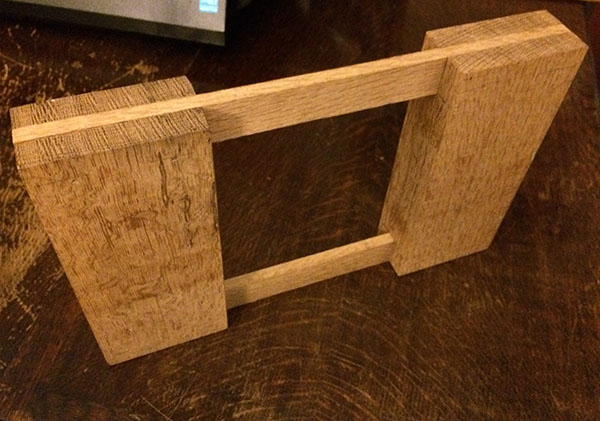
Temporary Braces: 1" thick x 2" tall x 18-1/2" long mild steel. Edge rails have a 2" gap less powder coat, approximately 1.91", edges are 5/8" tall and not parallel to horizontal axis. Roughly 109 degrees from horizontal access. I.D. of frame is 19". Centerline between jack screws is 16-3/4". Max length in corner top straight across ~18-1/2". Wooden Spacer: We created a 1.75" wide spacer between batteries, the hold down rods fit well with this distance between the batteries. 12-3/4" wide x ~8-1/4" from bottom of battery body to drip rail. Two pieces 1.75" x 3-1/2" x 8", with 3/8" x 1" slots for cross spacers. Two cross spacers 3/8" x 1" x 12-3/4" Jake Roulstone made a replica from some very nice white oak. We purchased 3/4"-10 hex cap screws 8-1/2" long, with lock nuts and hex nuts for the forward brace. We later received the photos from NUM and see they should be longer fully threaded screws. - Added a brass replica cap for the fourth (unused) nipple on the low pressure regulator.
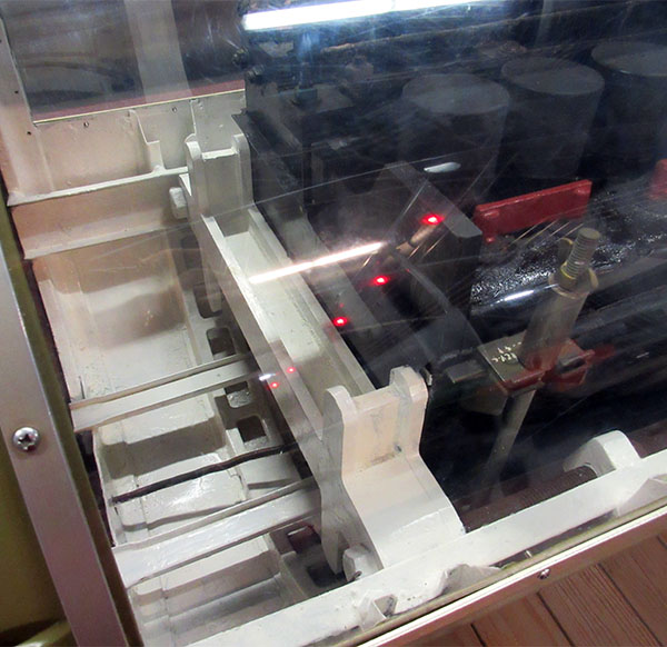
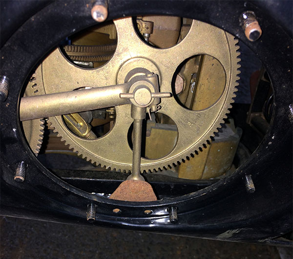
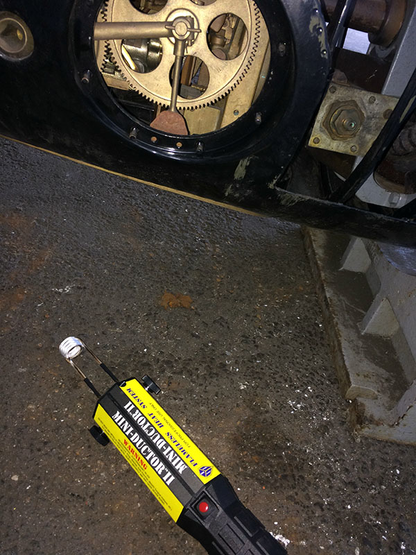
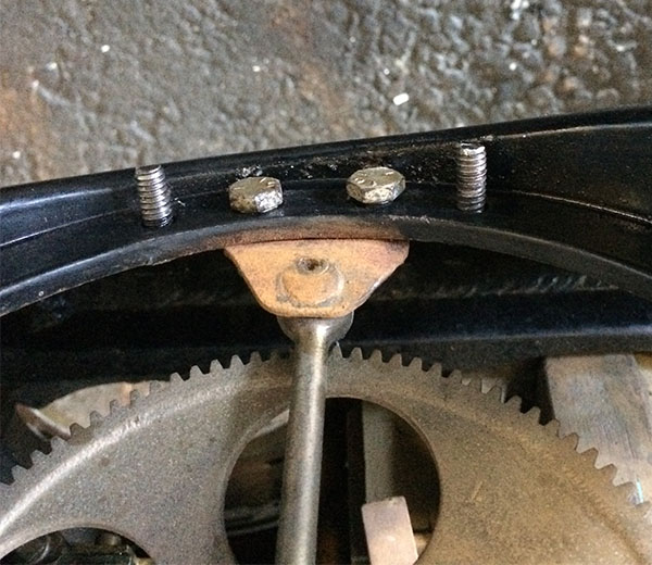
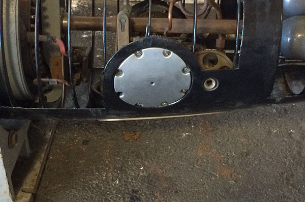
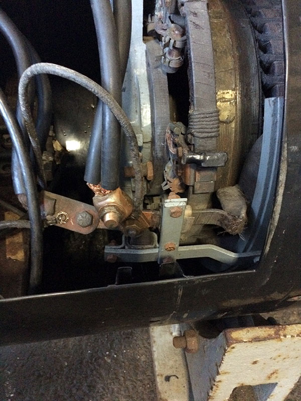
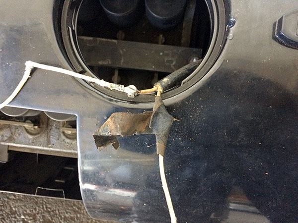
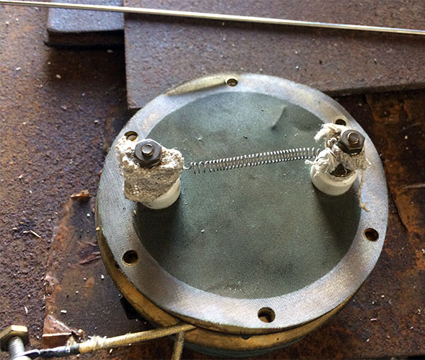
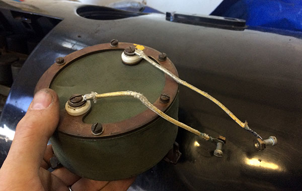
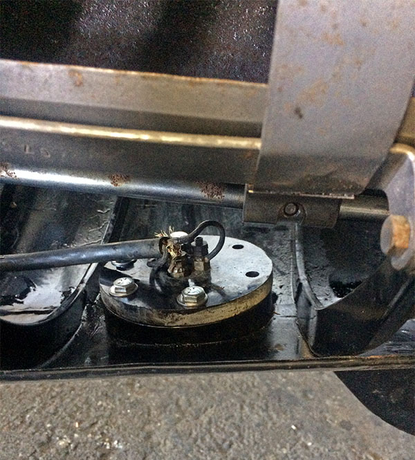
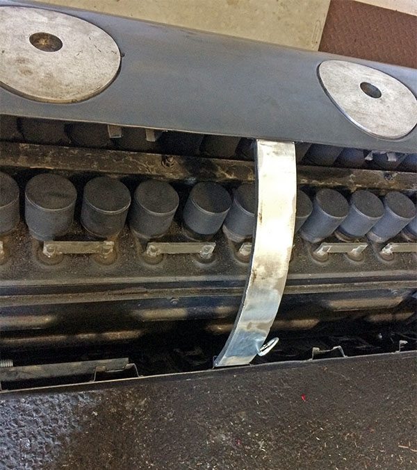
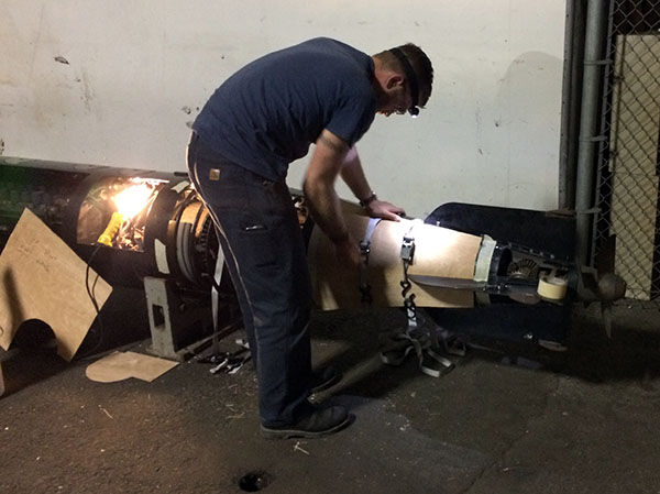
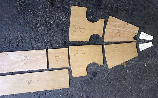
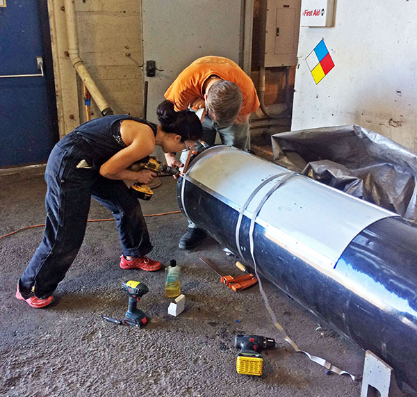
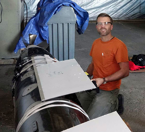
- Tail vanes: 1/4"-20 flat head screws that were missing were replaced with stainless steel screws. - The studs for the two hand access covers on either side of the gyro were powder coated and one was damaged. We used a donated Mini-Ductor induction heater to heat the studs to break down the paint with no noticeable damage to nearby paint. It was our first use of induction heating and worked really well. Mounted the cover with 1/4"-20 stainless nuts. Port side screws holding the bracket that holds the gear were replaced with appropriate length 1/4"-20 3/8 screws that do not interfere with the cover. Gaskets are missing and should be replaced if the excess powder coat on the machined surface is removed. - We lubricated moving parts that are accessible with LPS 2. We added grease in the grease cups. Enough of the support and structure is cut away (for example the starboard side of the universal gear) that the shaft should not be rotated too much, and only slowly by hand if at all. - The hydrogen burner power ring terminals were cut. Note there are bolted connections between the high temp wire and the wire running aft about 4 inches from the burner that are used to disconnect the wire leading aft. The internal hardware needs to be removed before removing the studs and ring terminals. We disassembled, rewound the distorted nichrome wire, and re-assembled. The bolted connection looked original and was covered with cloth friction tape. The damaged insulating cloth needs to be replaced. - The threaded mounting screw holes of the after body terminal flange that mounts the plastic of the external electrical connection were full of paint. They are hard to reach with the air flasks in place, but we partially cleaned four of the six and installed fresh screws. 1/4"-20, 5/8" long with washer. The other two should be cleaned if the torpedo is disassembled. We need to research which of the four terminals are for the hydrogen burner, and what the other two are used for. Maybe the other two are for a heater that is not installed? Or for checking battery voltage or charging (probably not it would cause a ground?) The extra two conductors and terminals are not described in the manuals we have. - The end of the negative cable in battery compartment, and the positive cable in the after body were cut off during disassembly for powder coating in 2006 and not saved. We replaced these with modern screw type fittings, but we should create proper crimped and soldered replicas based on the two intact ones. - Battery wires and hydrogen burner wires were dressed to the case. It uses cloth friction tape to join the pairs, and thin slot and tongue ties. National Band & Tag Co. has donated #1609 1/2" x max 1-5/16" diameter, aluminum ties. The originals were plated copper. There is one original tie remaining on the hydrogen burner wire aft of the burner. - High pressure pipe from start valve to motor start switch was missing when we got the torpedo in 1999. This is 3,000 PSI. 1/4" OD NPT pipe. We used brass flare fittings (instead of steel HP) and copper pipe for a replica. Seeing the manuals after installation we think the routing should be higher in the case. This will have to be replaced if the motor is restored to the correct orientation. - Tail cone and after-body/battery joints were missing screws. B2 Machining made replicas copied from one of the originals. They are 5/16"-24, 75" thread, with a 1/8" shoulder that is .40" diameter, .220 square head. - There are some broken screws in the battery/after-body joint from 2006 that should be extracted. - Replica screws used in 2006 for both after body and tail were un-plated steel. They should have been CRS/stainless, or at least plated. We replaced the accessible ones. - Some of the holes do not line up correctly and do not have screws in the battery/after-body joint. It is hard to tell without separating the sections where the problem lies. - Visitor proofing. We received permission from NHC to drill and tap the historic fabric for the mounting screws. We had sheets of .116" polycarbonate donated by Calsak Plastics. Polycarbonate scratches more easily than acrylic but were were able to cold bend it in place. To fasten the plastic, we used #10-32, 1/2" and 3/4" long stainless steel button-head socket cap screws and 1" x 1/8" aluminum strips to reduce the number of holes in the case. We used ratchet straps to ease assembly. The pieces are not interchangeable. We will keep the wooden templates in collection so replacement plastic can be more easily made in the future. We created a false frame to support the middle of the thin plastic on the wide cutout. The open space inside of the frames is roughly 2" wide x 1/2". Note that it can slide inside the frame and is difficult to remove if it does. Oliver Hickman and Lauren Usui created the visitor proofing. Bill Doll helped with the final installation.
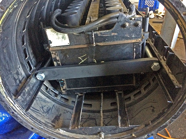
- We found two torpedo straps in our collection and installed one on the loading tray. - Asked curator to search for photos from 06, parts not in the box, and master copy of 1944 version of OP 946 manual, restoration notes. Asked Harry N., Al M., Aaron W., and Jim K. if they had photos or notes from 2006. None of these were successful. - Created replica strong backs that work with the shortened torpedo loading tray rails. This facilitate re-arranging the torpedoes and maintenance. - We should to go head to tail checking for missing and incorrectly installed parts. - Many steel parts are lightly rusted uncoated steel and probably were originally parkerized, or uncoated. We have put LPS 3 on them, we need to monitor them before choosing a long term plan. - There are screws missing on the start switch/valve that hold it in the case. 1/4"-20, 1/2", bronze.
- Additional parts that are missing: - Motor was re-installed in 2006 rotated out of position. It should be rotated if the battery and after body are separated. - Many case gaskets missing. Most will not fit without removing the excess powder coating on machined surfaces. - Air pipe for warhead (exercise head) is bent up aft of the bulkhead and covered with paint. The flange needs to be slid down to the bulkhead. It should be stretched aft if the battery and after body are separated. - The 2006 powder coat needs to be removed from all the machined surfaces of the case. The battery compartment and after body were not properly mated, one or the other is out of round. There are broken and missing replica screws from 2006 on the battery/tail section joint. Some of the 2006 plain steel screws (they should be the new replica CRS) are still in place. Check the screws and screw holes on the bottom of the torpedo that were not easily accessible. We created enough stainless steel replica screws. The powder coat, out of round sections, and mis-installed fittings have increased the maximum diameter of the torpedo from 21" to something over the 21-1/8" diameter of the torpedo tube. Do not attempt to load this in the tube. - Find out who did the powder coating and replica battery hangers in 2006 so they can be added to the acknowledgements.
2006 Crew:
2016 Crew:
Donors:
|
