Torpedo Rail Strongback Project Notes
History and Problem Statement The goal of this project was to allow shifting of the torpedo loading trays (also known as torpedo skids). Our immediate need was to enable the crew to get between the torpedos and pressure hull to prep and paint coatings outboard of the torpedoes. We also need to be able to move the torpedoes to measure and fit the center support rails for the sliding berths under the torpedoes. Long term we need access behind the torpedoes for maintenance once or twice a year. We wanted a system that would allow safely rigging and moving the torpedoes in less than an hour, and to restore the room to accept visitors in the same time frame.
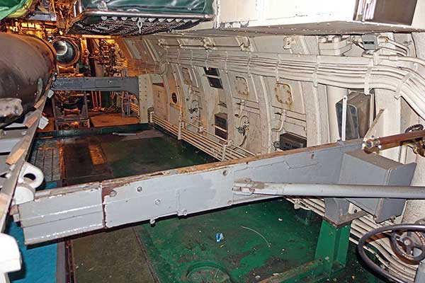
History and Problem Statement: Note that the FTR (forward torpedo room)-port-upper-track appears to be a replica and is missing any tray locking holes, or berth chain details. This is consistent with the oral history. We have an intact one of these in the warehouse that may be from Pampanito or another boat. FTR-stb-middle is cut short just inboard of the tray lock. FTR-lower tracks are intact. ATR (aft torpedo room)-stb-upper appears to be historic, and cut. ATR-stb-lower is a replica made of a block of steel with no details. The locking pins are missing from the one original rotating strong back. We have the drawings so it can be restored. Any plans need to minimize changes to the historic fabric, and those changes need to be documented and reversible. If the stairs are ever replaced, they should be aluminum to be lighter, a bit narrower, and mounted just a bit to starboard so the tracks can be restored.
Completed Modifications to the Non-Historic Stairs: The handrails are 1" IPS (1.31" O.D.) pipe on the top rail and verticals. The second, bottom rail is 3/4" (1.03" O.D.) pipe. So used x6 #70 couplings of 1", and x2 of 3/4" per room.
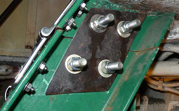
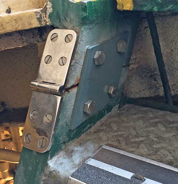
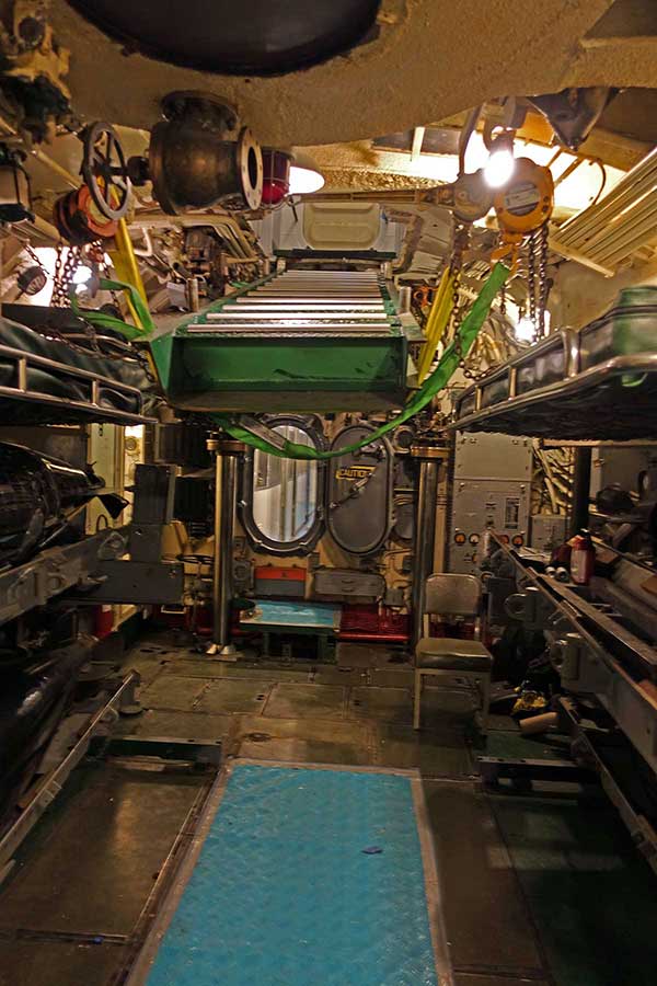
In the Forward Torpedo Room the top of the stairway was cut and had 1/4" plates bolted on both sides for a museum era torpedo loading evolution. We gave the same treatment to the stairs aft. In both rooms, we added 2" wide hinges over the cut. We can now remove the handrails and side plates, and use a pair of chain hoists to raise the stairs up out of the way in minutes. Or remove the hinges and side pieces to lower the stairway to deck or out of the boat as needed.
Working Strongbacks:
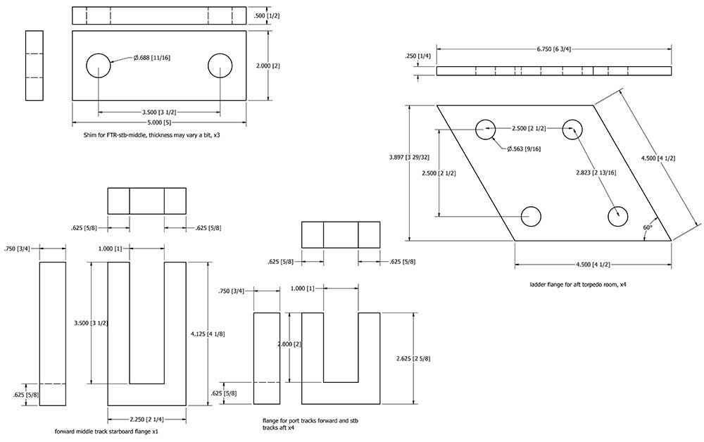
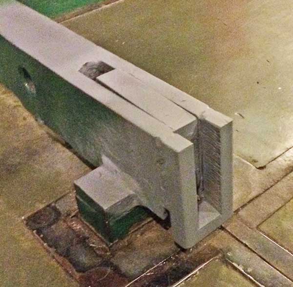
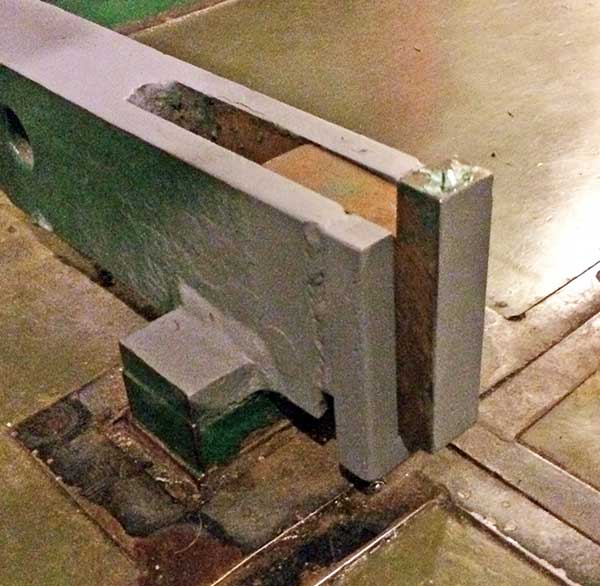
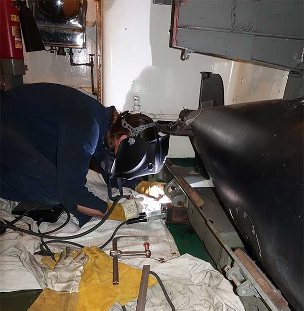
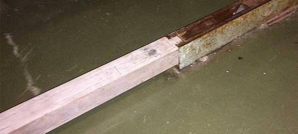
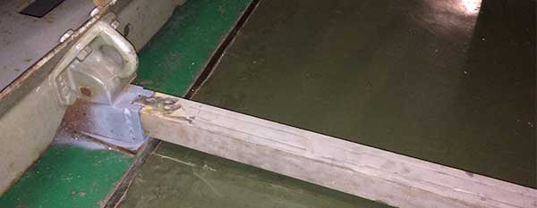
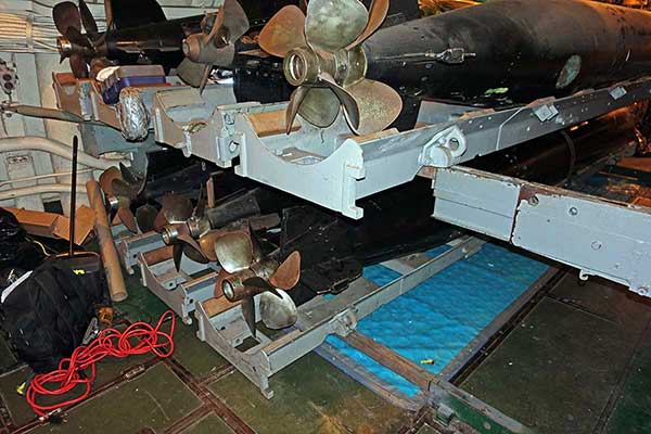
In the After Torpedo Room (ATR), the aft tracks (near the torpedo tubes) are intact. There are two 22.5" strongbacks with one locking hole on deck behind the visitor proofing. Note that the rotating type strongback for loading now in the FTR will fit in either position in the ATR. The fwd-upper-port and fwd-lower-port tracks are intact. The fwd-upper-stb is cut, and fwd-lower-stb is a short replica. Where the original tracks are intact our longer replica strongbacks fit in the 1" wide slot that the original strongbacks used. That leaves five other interfaces. After examining several alternatives, we welded a 3/4" deep, 1" I.D., 2-1/4" O.D. U-shaped end flange on the existing rail ends that had been cut short. We then created long strong backs to fit.
Acknowledgements and Thanks:
Autodesk, CAD software, http://www.autodesk.com
The drawings of the original parts are located at:
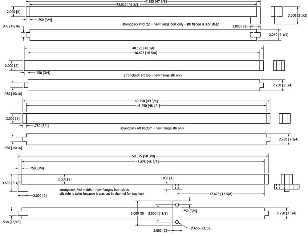
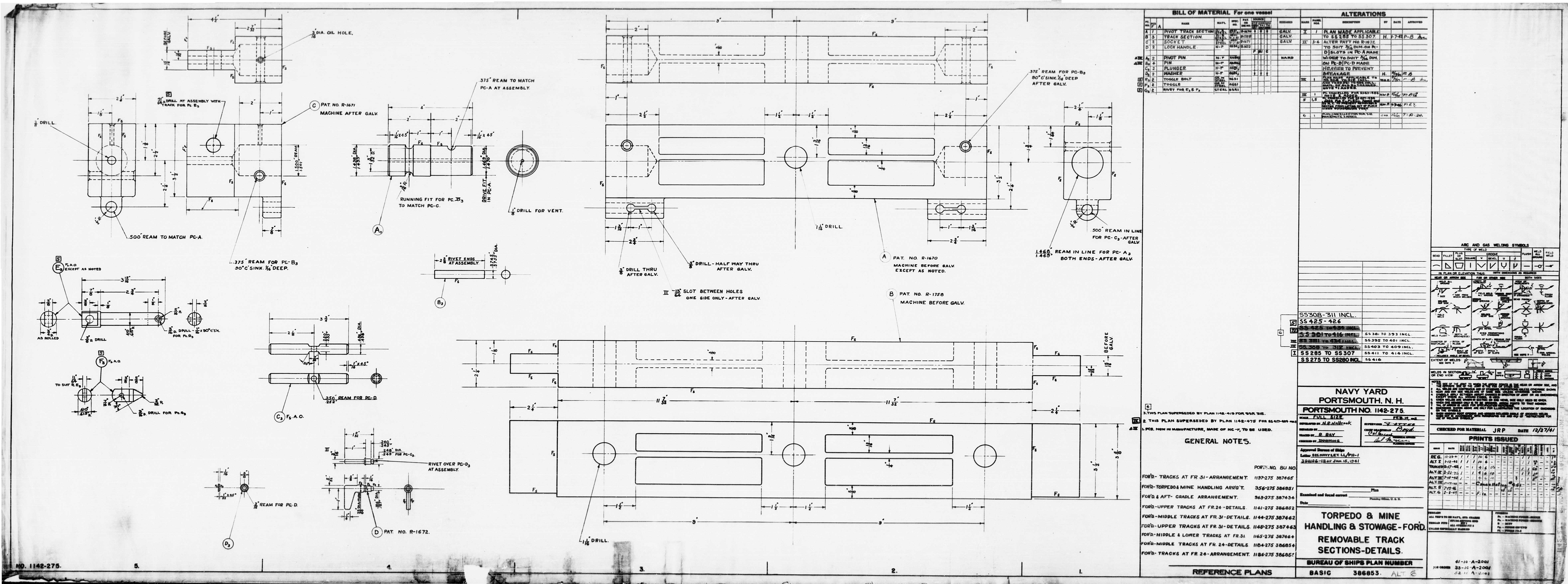
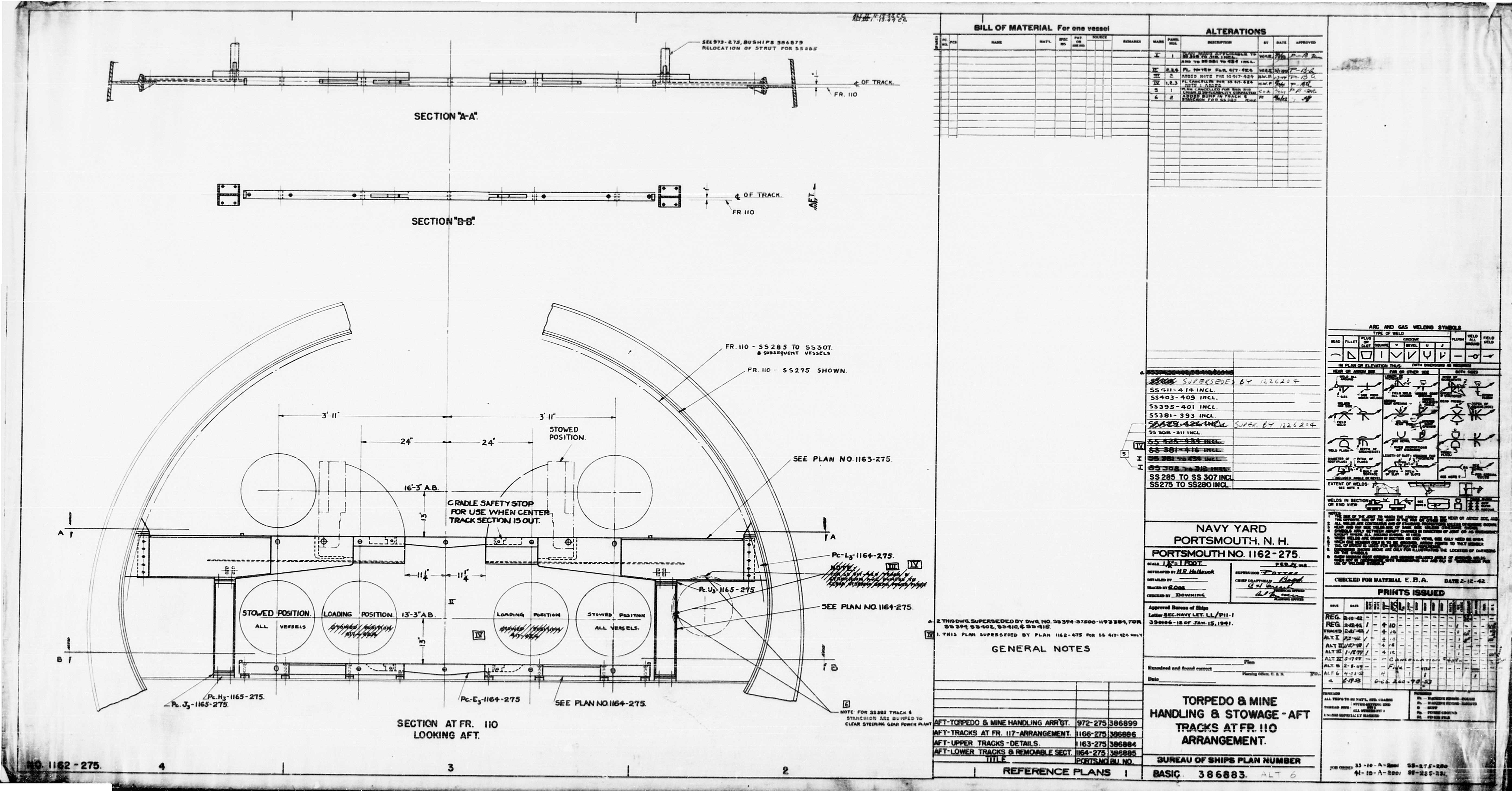
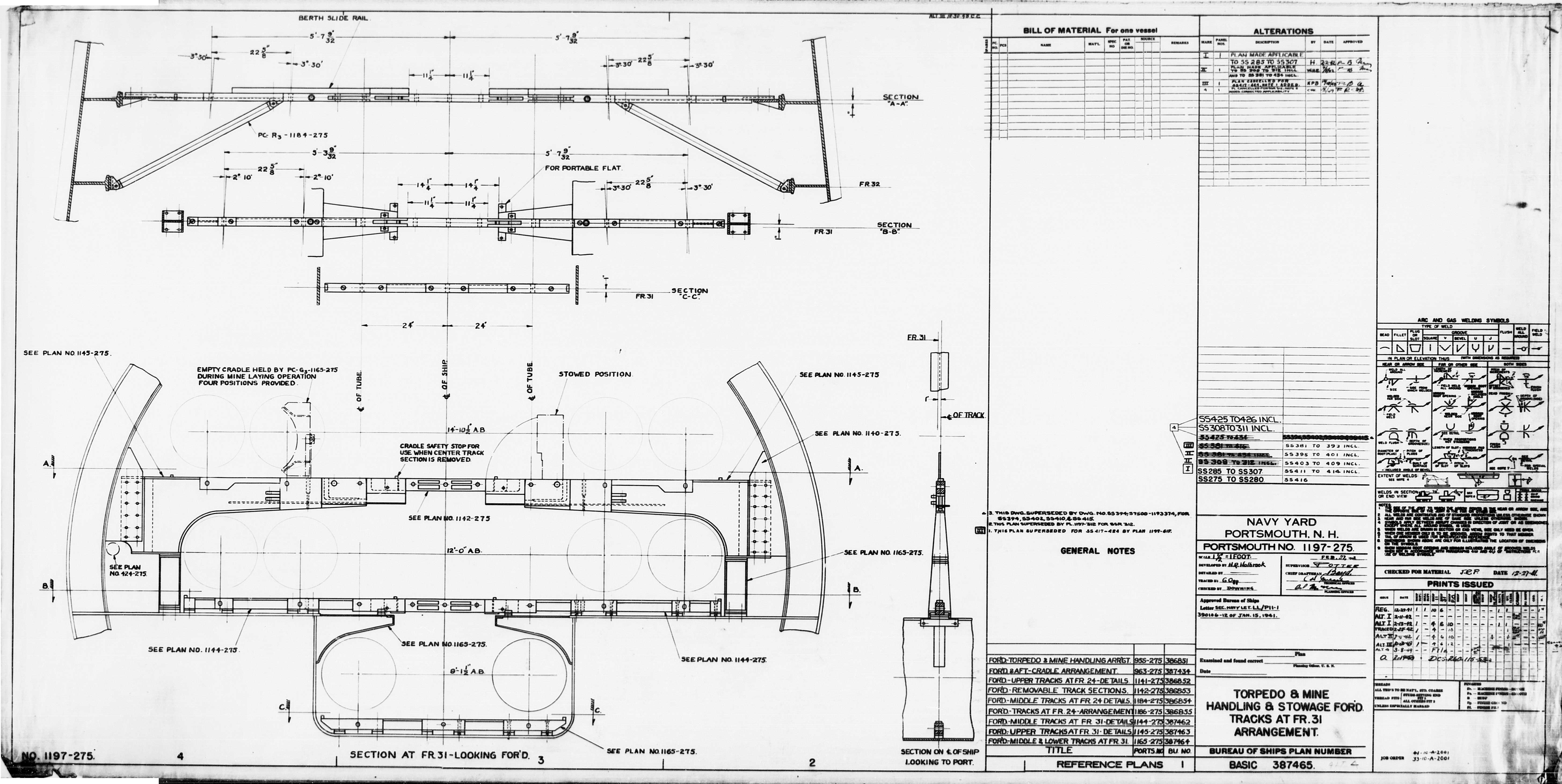
Concept Drawings: The outboard, storage position lock holes are two 1/2"R hemispheres with an 1/8" gap allowing 1/8" vertical play, but not the ones at the tube and ship centerline we are replicating. Ship centerline holes are 24" from loading position (tube centerline) holes. The centerline of the holes are 1-9/16" from the top. Fwd. room strongbacks also have two extra holes 9" from centerline hole. The strongbacks will need to be extended to provide room for the holes.
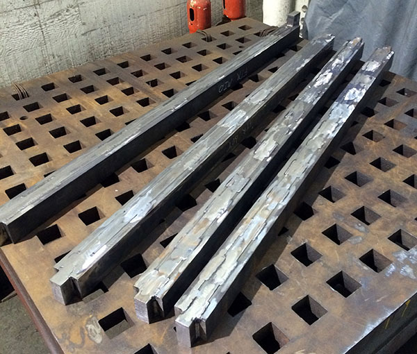
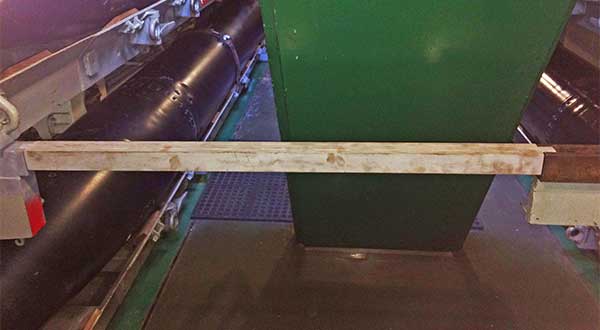
We created the strongbacks from a 1" x 2" center bar with with two 5/8" x 2" pieces welded on each side. The as built dimensions reflect a little extra length of tab on the historic un-modified flanges, and a minimum of 1/32" clearance on each end. They have been welded, welds ground flush, and test fit. At some point in the future we might mill or file the tops flat, and extend and drill for the locking holes. If we plate or paint these, we will need to take a bit more off the shoulder clearance because they are snug fit. |

  Excerpt from lower track drawing showing some original dimensions 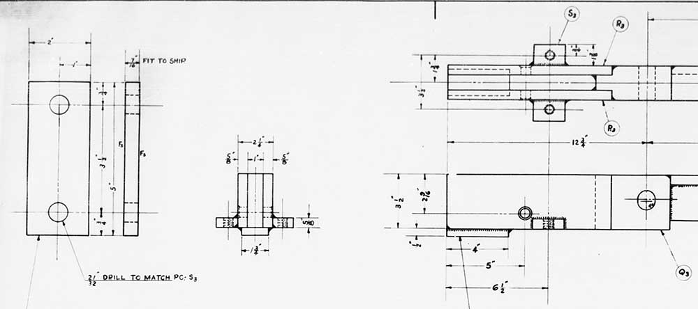 |
| Photos After:
|
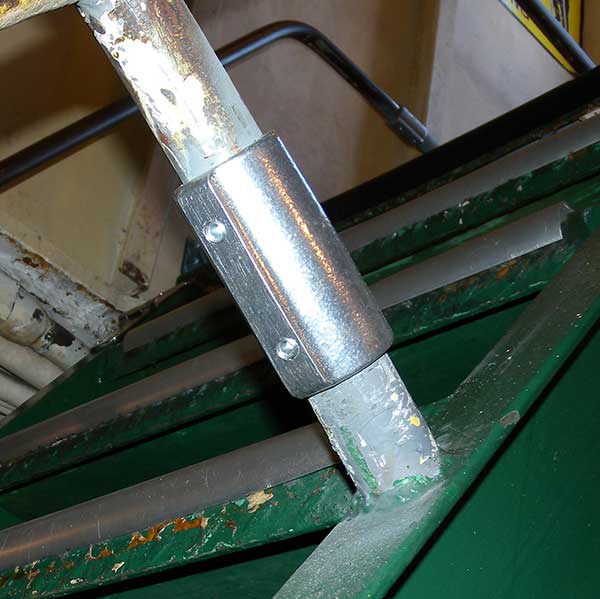
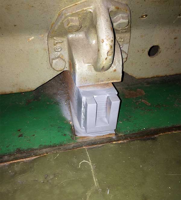
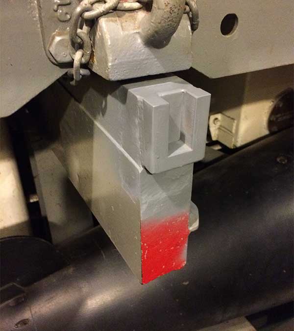
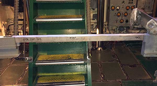
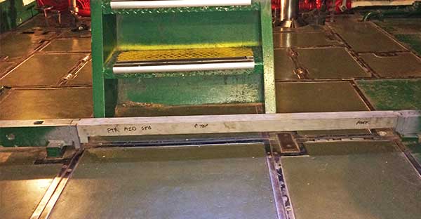
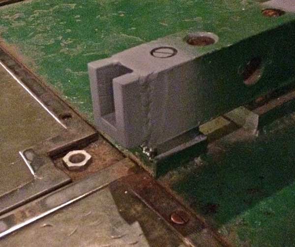 Fwd, port, middle, track with added flange.
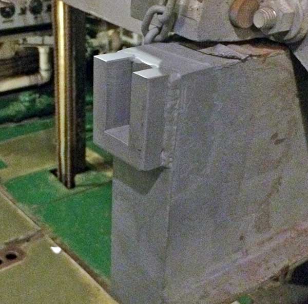
Reference (Before) Photos: 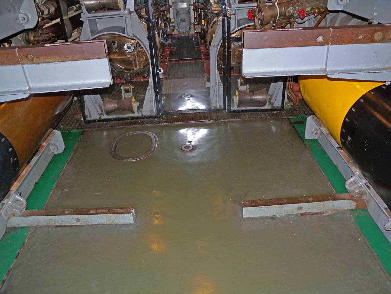 atr-aft-DSCN1222.jpg atr-aft-DSCN1222.jpg 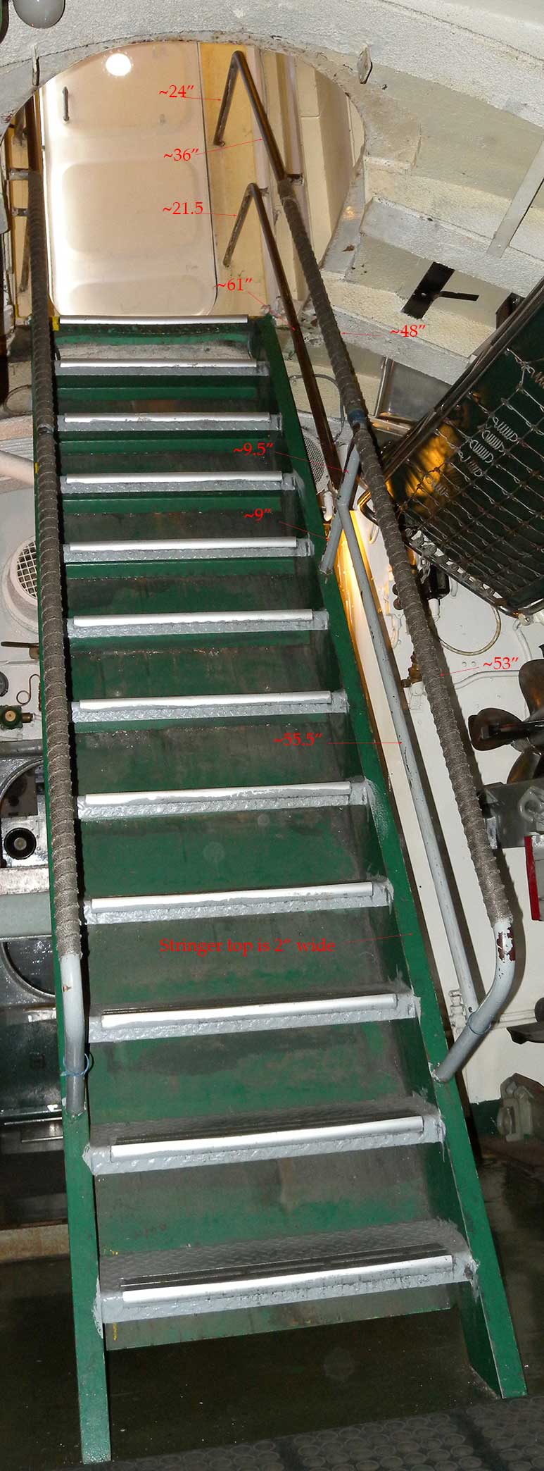 atr-rail-DSCN1280.jpg atr-rail-DSCN1280.jpg 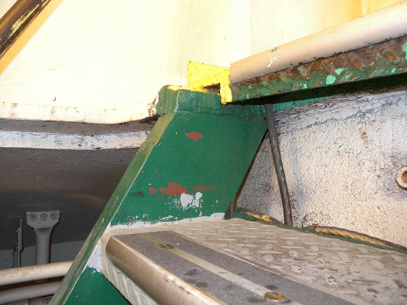 atr-ladder-DSCN1218.jpg atr-ladder-DSCN1218.jpg 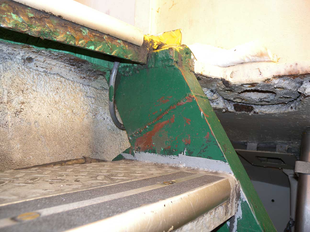 atr-ladder-DSCN1219.jpg atr-ladder-DSCN1219.jpg 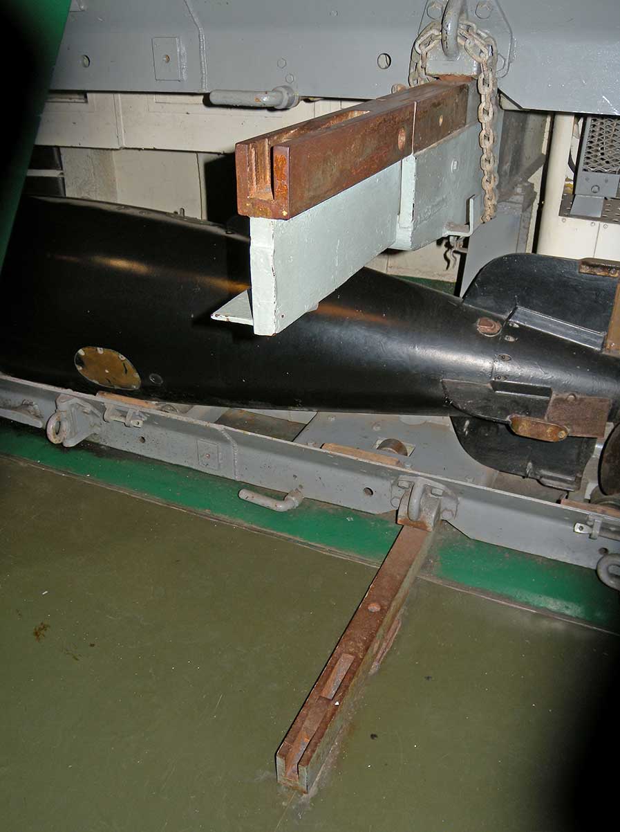 atr-port-DSCN1162.jpg atr-port-DSCN1162.jpg  atr-port-DSCN1169.jpg atr-port-DSCN1169.jpg  atr-port-DSCN1171.jpg atr-port-DSCN1171.jpg 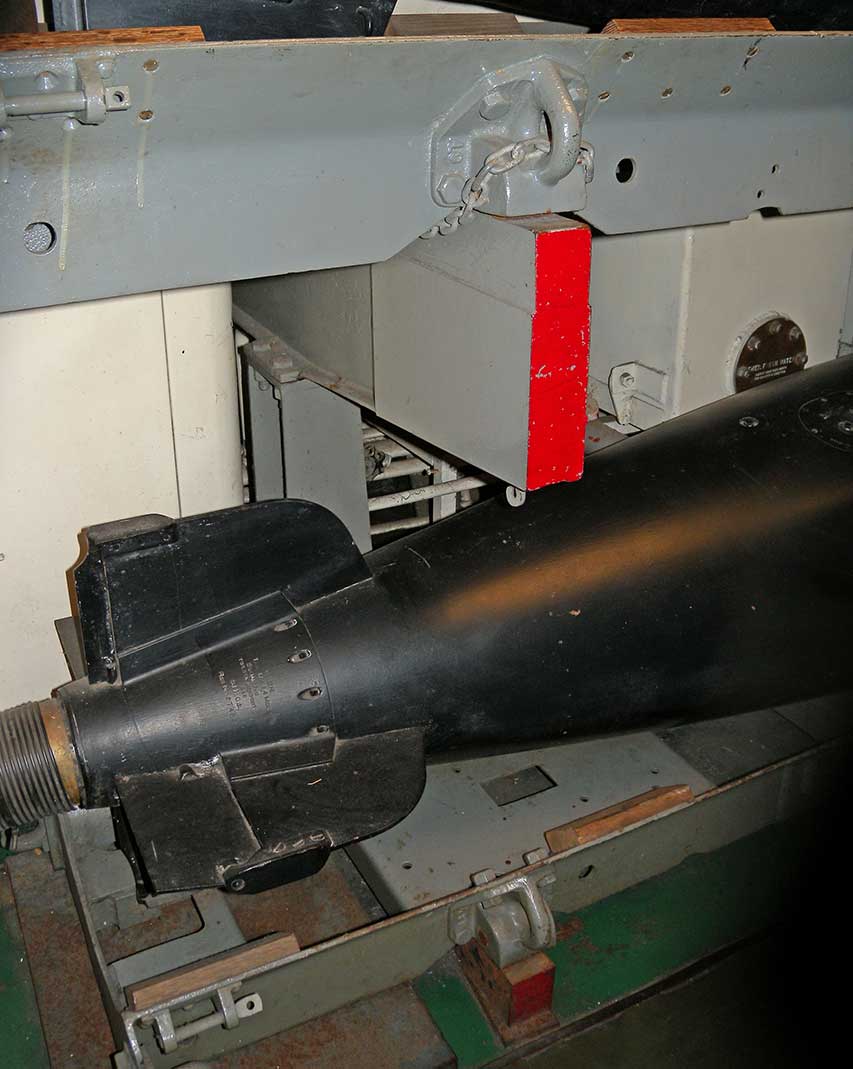 atr-stb-DSCN1163.jpg atr-stb-DSCN1163.jpg 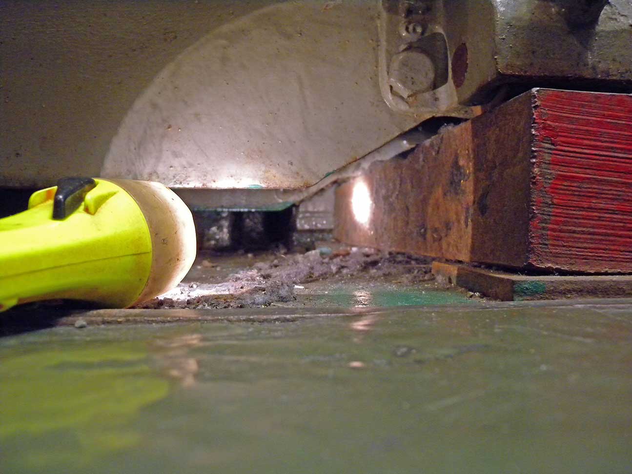 atr-stb-DSCN1236.jpg atr-stb-DSCN1236.jpg 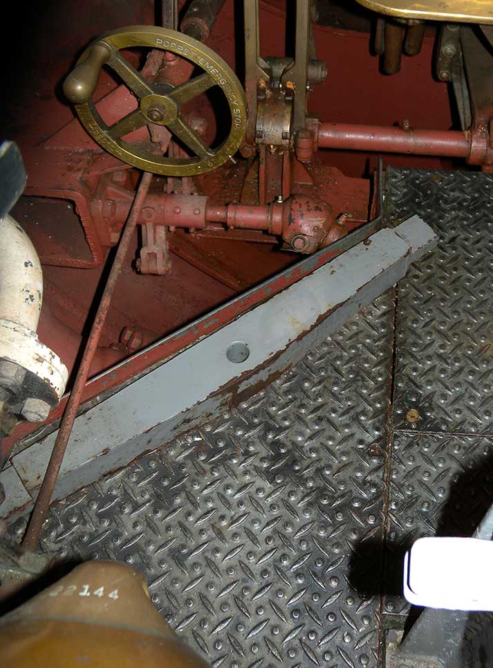 atr-strongback-DSCN1174.jpg atr-strongback-DSCN1174.jpg 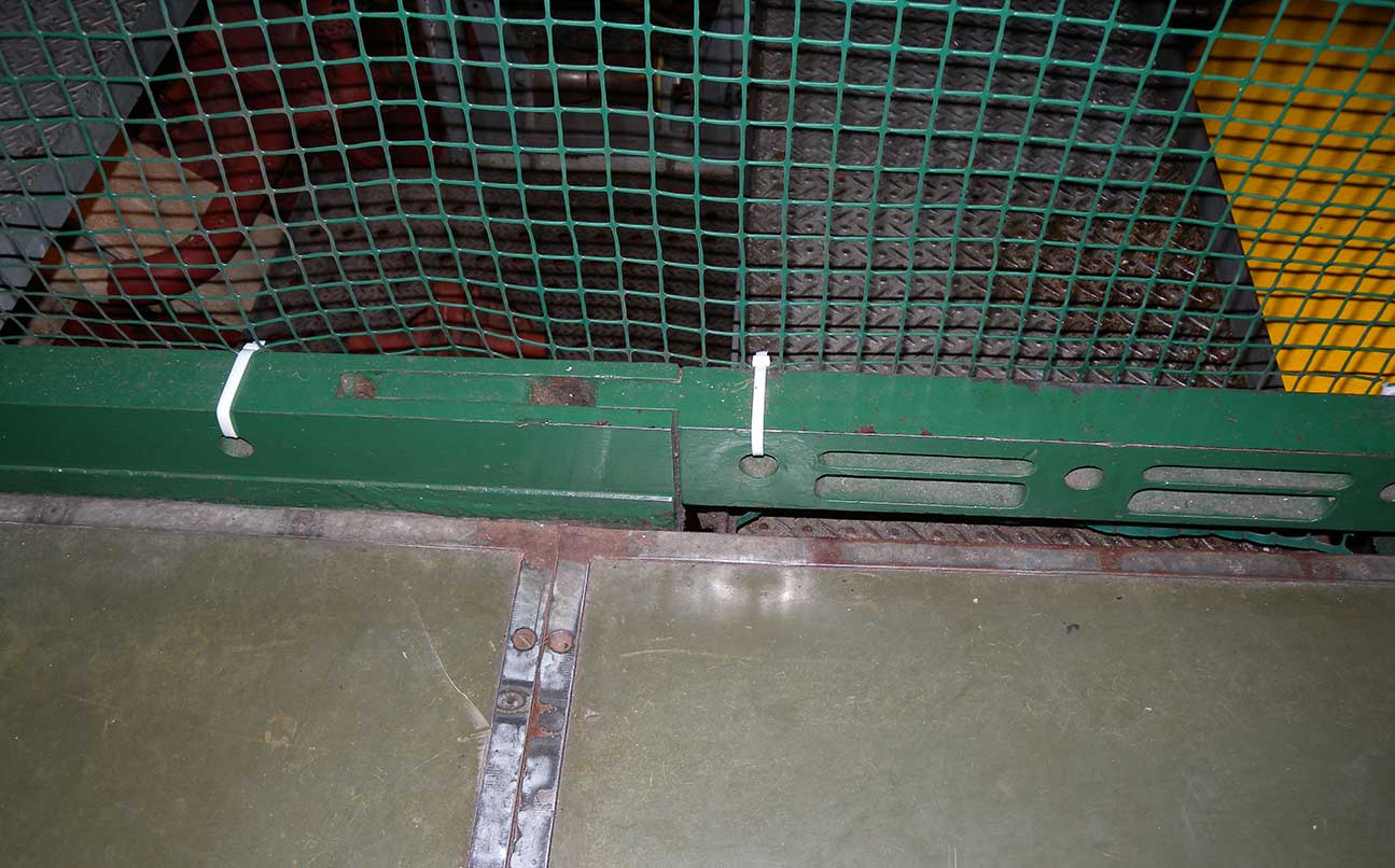 ftr-fwd-DSCN1045.jpg ftr-fwd-DSCN1045.jpg 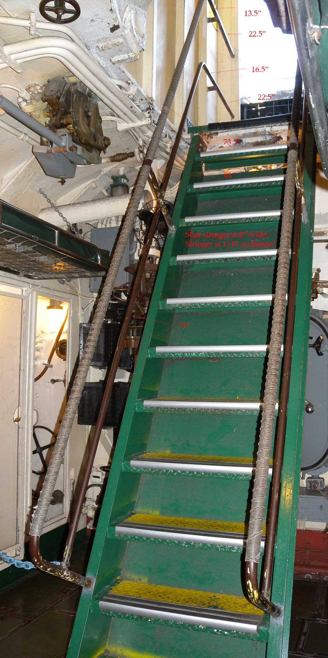 ftr-rail-DSCN1285.jpg ftr-rail-DSCN1285.jpg 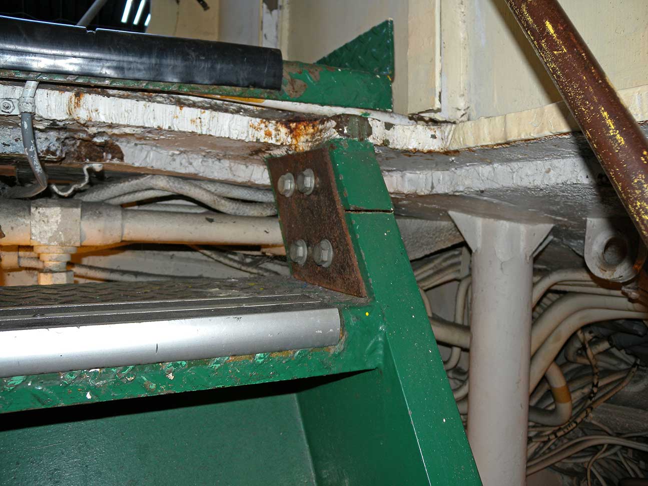 ftr-ladder-DSCN1255.jpg ftr-ladder-DSCN1255.jpg 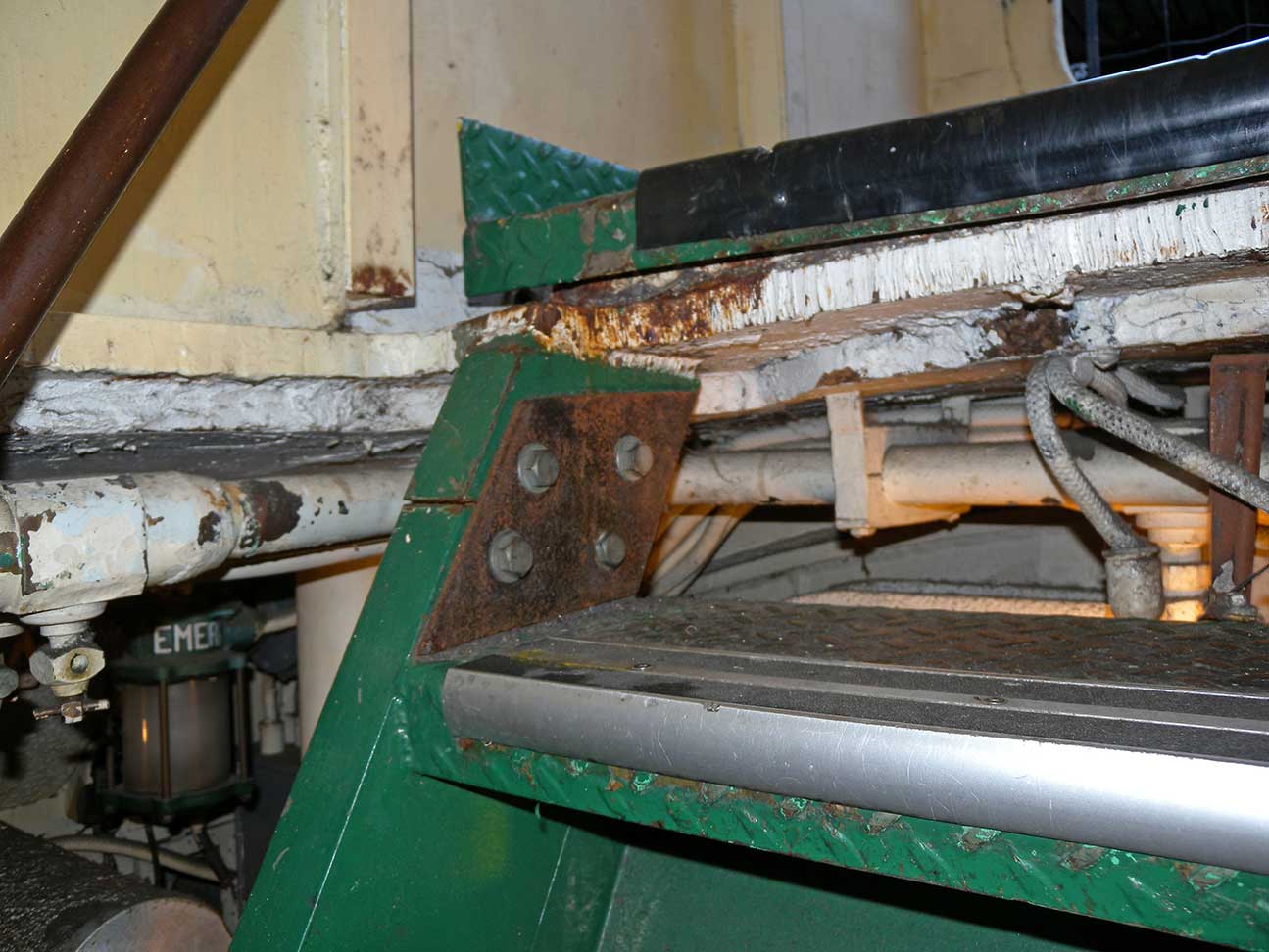 ftr-ladder-DSCN1256.jpg ftr-ladder-DSCN1256.jpg 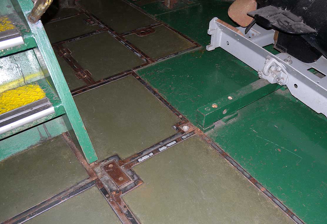 ftr-port-DSCN1043.jpg ftr-port-DSCN1043.jpg 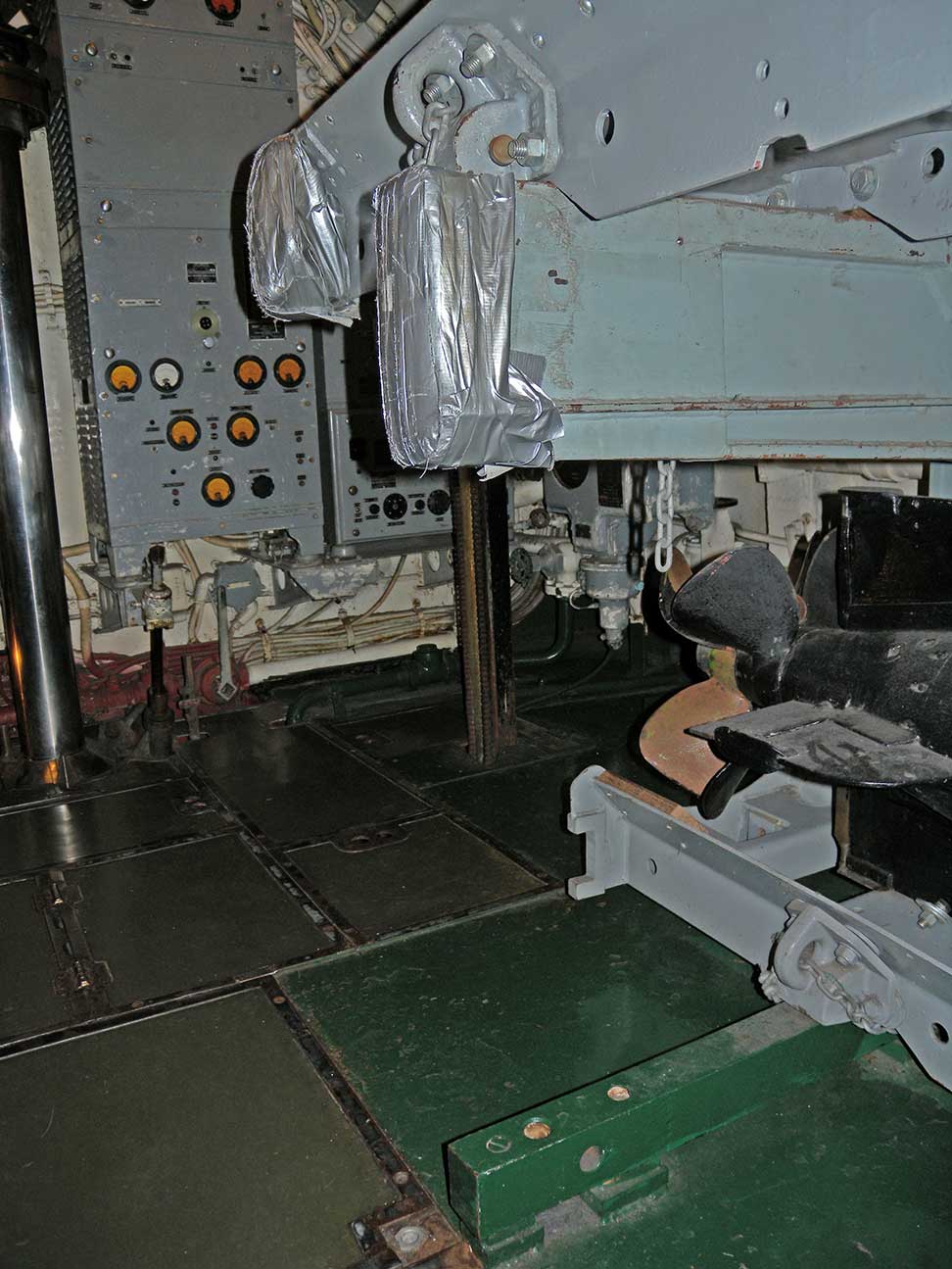 ftr-port-DSCN1047.jpg ftr-port-DSCN1047.jpg 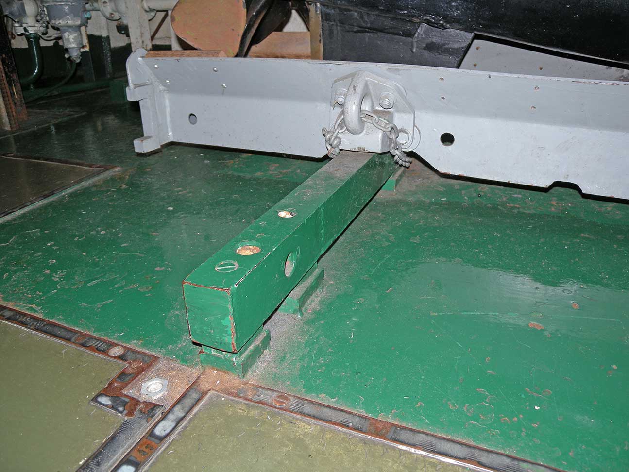 ftr-port-DSCN1245.jpg ftr-port-DSCN1245.jpg 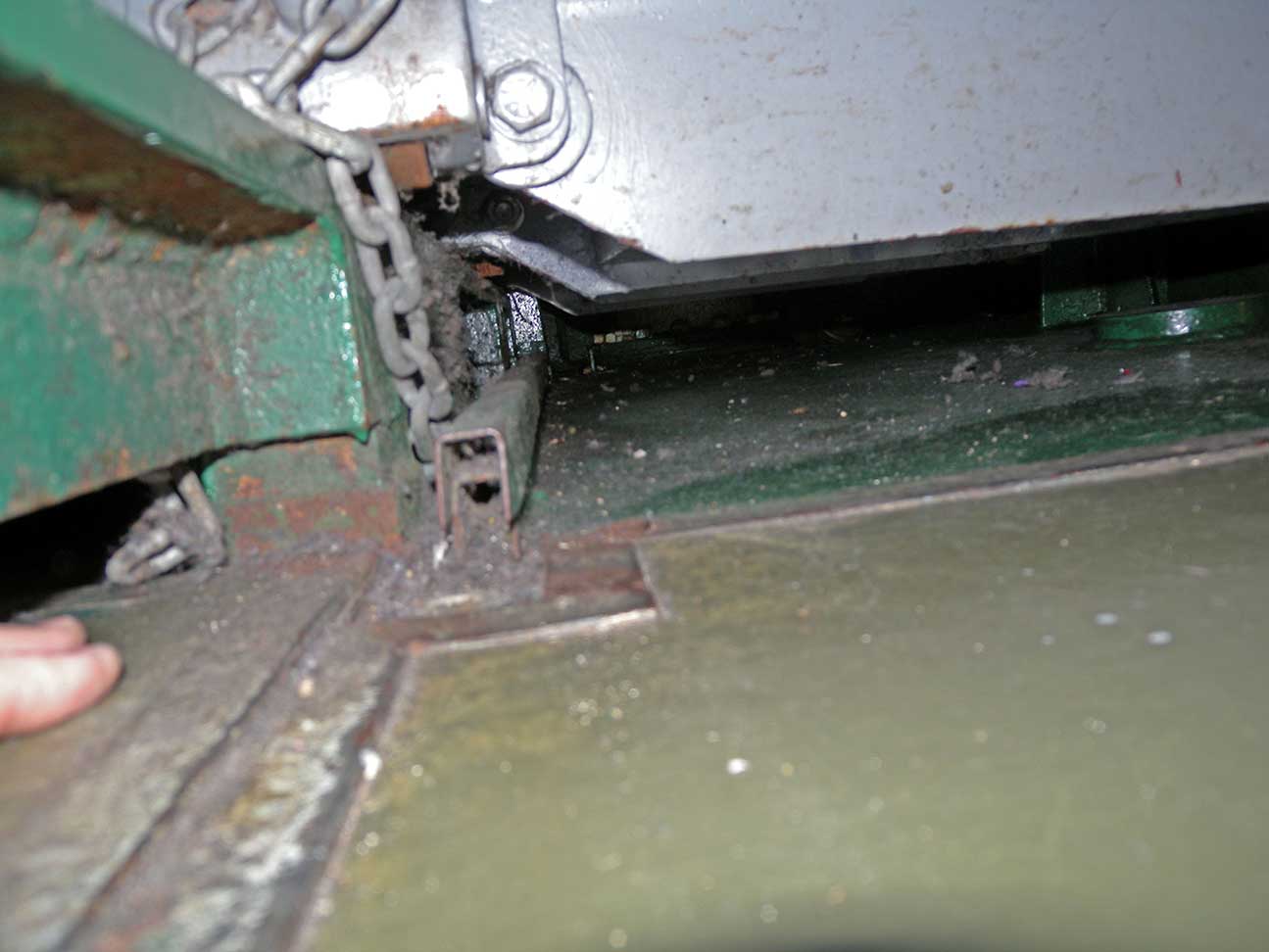 ftr-port-DSCN1249.jpg ftr-port-DSCN1249.jpg 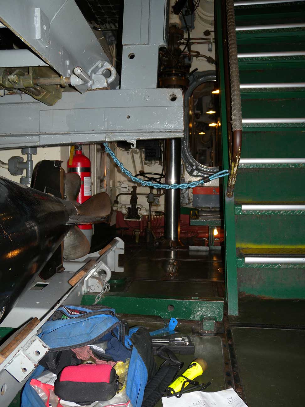 ftr-stb-DSCN1049.jpg ftr-stb-DSCN1049.jpg 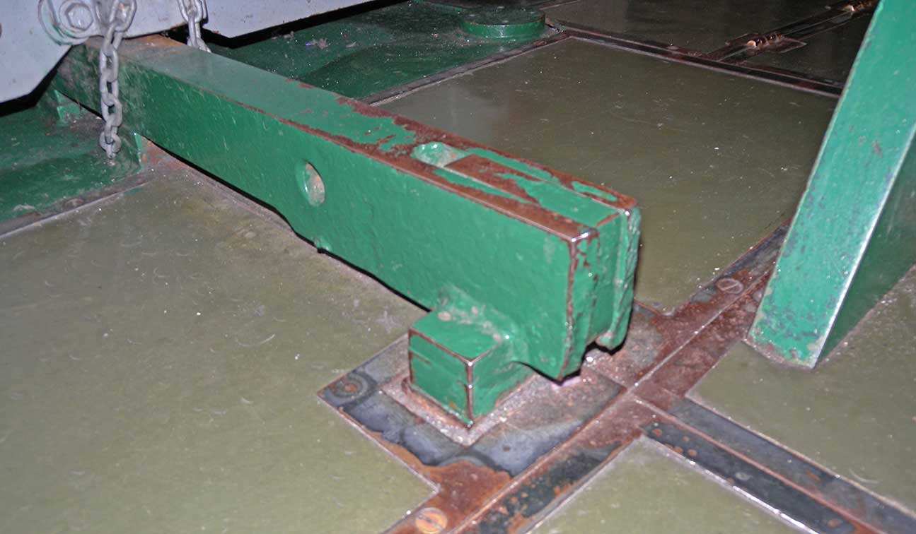 ftr-stb-DSCN1240.jpg ftr-stb-DSCN1240.jpg 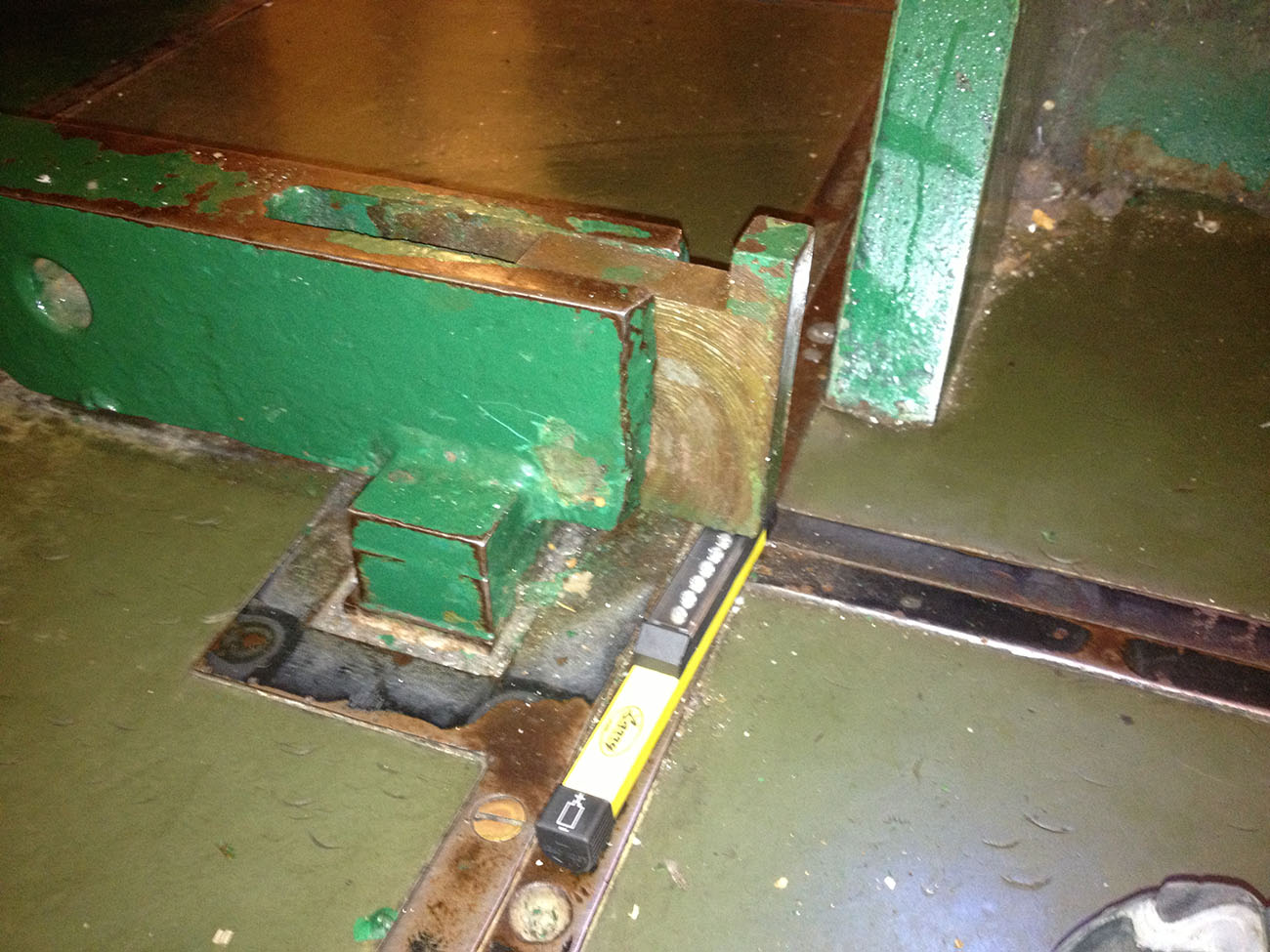 ftr-middle-lock-open-IMG_0606.jpg ftr-middle-lock-open-IMG_0606.jpg 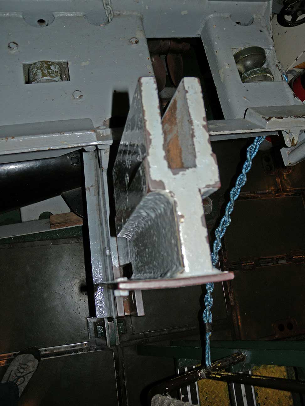 ftr-stb-DSCN1243.jpg ftr-stb-DSCN1243.jpg 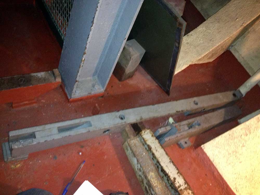 extra-rail-parts-IMG_0601 extra-rail-parts-IMG_0601 For ref, these are 22.5" and 44" long
|