NOTE: THIS IS A WORKING DOCUMENT. THERE WILL BE CHANGES AS WE COMPLETE THE WORK. The purpose of this page is to document the changes planned & completed, and acknowledge the people and companies that made it possible.
Background:
USS Pampanito was built with a floating ground system on all its electrical services (250 VDC, 120 VDC, 115 VAC, 6 VAC). For more information about the power on the boat see Submarine Electrical Installations, and original drawings. This was standard practice in the 1940s, but requires a vigilant crew to detect and correct dangerous ground faults before they become a hazard to the crew or equipment. Many problems were introduced during the 1960s when she was used as a shore side trainer, this included applying AC on DC circuits, crossing 120VAC on 250VDC circuits, improper grounds, etc. Some of these were cleaned up in 1981 when Pampanito became a museum, but many remained. When moved to pier 45, she was originally supplied with a 60 amp 120/240VAC shore power connection in aft engine room. Over time the battery tank (lower flat of after battery) was emptied, and a rectifier added to provide DC power on the original Aux distribution battery cables during restoration projects. The rectifier was supplied by a 480V, delta 3p+g, shore power cable led through a removed salvage value in the crews head and through a battery vent to the after battery tank. Note that the main propulsion power battery, engine room, maneuvering cubicle are not restored or connected to any source of power.
The next set of major changes was the 1994-1998 restoration of her historic DC power distribution. During this project lead by Chief (ret) Len Vaden, all the ground faults on then operated equipment and circuits were found and corrected. Most were found in light fixtures where the heat from the bulbs damaged the wire in the fixture, these were sleeved with heat shrink tubing. Others were in crude patches between AC and DC circuits, dirt and loose connections in switchboards, DC lighting voltage control dimmer, galley range, and in changes made by an amateur radio club in the radio room.
- Fuses were removed from all unused or untested equipment/circuits. All the lighting and AC fuse values were checked, many incorrect 15 amp fuses were replaced with 10 amp or 5 amp.
- A 75 kVA 240/120v transformer and a 40 kVA rectifier were added in after battery to supply the day to day 120 VDC lighting, 250 VDC Aux bus, and 120 VAC motor generator circuits. The wires were disconnected from the locomotive style voltage regulator (dimmer) on the lighting circuit and its panel repaired. The negative four-wire battery cable from after battery to the control cubicle in maneuvering was unbolted on both ends (FB-0202), and three of its wires used to bring 120VAC to the motor generator switchboard (output of two of the four AC MG sets) from after battery. The original forward battery and after battery Aux power bus tie was connected with the disconnects in forward Aux distribution panel (control room) and aft Aux distribution panel (maneuvering). The Aux generator field switch was set to the center, off position. The forward battery lighting center tap was set to the opposite battery half from the aft battery to provide lighting power on both sides of the center tap. The 120 lighting 3 pole switch in forward engine room was set to after battery. All the circuits on the boat were restored to their original voltage and frequency.
- A 9KVA 208/120v transformer was installed in after battery to supply the emergency lights, non-historic sewage pump, control circuits, and a receptacle next to the water heater in crew's mess.
- The port and starboard emergency light circuits were bridged in after battery (it would have been better to do this in one of the torpedo room marker buoy boxes) and a 208v computer style UPS with custom control including a rectifier were added. The emergency light switches were turned on, and the handles removed. This greatly improved the visitor experience, coverage, lowered cost, and improved reliability over the separate two headed battery operated units that were replaced.
- Jumpers were added at the lighting 3 pole switch in forward engine room, and the forward Aux distribution panel in the control room to supply high current 120VDC for the torpedo gyro indicating setting regulator (GISR) in the forward torpedo room. The GISRs are the only high current 120VDC loads on the boat.
Pampanito is fortunate to have close relationships with the leading members of the San Francisco Bay Area working maritime community. Through them we have learned about newly available equipment, standards, and practical experience that we are now applying to make both our shop and the boat safer. We are particularly thankful for the leadership of Master Chief (ret) Charlie Butcher, and the good example of Manson Construction.
Goals of the 2018-2019 Project:
The overall goal of this project is to improve the personnel and equipment safety at the USS Pampanito facility without compromising the preservation of the hull. We also want to make the system easier to understand and maintain over time. Lastly, identify opportunities for future energy conservation projects.
On the Shore Power Supply to the Boat:
- Limit the instantaneous ground fault current that might occur (for example damage to the shore power cable in a storm) on the 480 VAC, 100 Amp circuit to a level that will not cause an arc flash or explosion. We chose 5 amps which is safe for equipment vs. the uncontrolled 20,000+ amp arc flash was likely in an unprotected circuit of this size. Provide warning that a fault occurred.
- Also on the 480VAC high power supply to the boat. Always warn, and during normal operation disconnect the power on ground faults on smaller level faults that could be dangerous to human life. This is analogous to the GFCI that protects most bathroom and kitchen receptacles. Provide a way to warn without disconnect for testing and repair.
- Make it easier and faster to disconnect Pampanito shore power cable during an emergency.
- Remove the nuisance and potential hazards of the separate power cable over the brow to the non-historic deck lights.
- Move the shore power connection on the pier clear of the future location of the brow to facilitate the planned movement of the 5" gun to its historically accurate position aft.
- Eliminate stray current problems caused by the Port of San Francisco shore power supply, electrical problems of other tenants of pier 45, stray currents from other ships, poor grounding on shore, etc. The stray currents are hazardous to the boat's hull (galvanic corrosion), its coatings under water, nearby swimmers, visitors, and crew.
On the boat:
- Continuous monitoring for ground fault, or GFCI on the 120VAC, 208 VAC, 250 VAC circuits supplied by transformers in after battery on both historic and modern distribution on the boat. Eliminate reliance on a periodic checks by a trained volunteer.
- Continuous monitoring and warning of faults in the insulation on the ungrounded historic 250 VDC main bus, 120 VDC lighting and 250 VDC emergency lighting circuits. Restored 250 VDC emergency lighting circuit to ungrounded. Eliminate reliance on a periodic checks by a trained volunteer.
- Eliminate running cords through doors or hatches for common tasks to prevent tripping hazards, and keep the the hatches and doors available for damage control. Minimize the use of the limited historic 120 VAC power distribution on the boat. Provide GFCI protected power for receptacles commonly used with portable cords. Reduce the need to use long portable cords.
- Facilitate line of sight available disconnect on portable welding cords.
In our Shore Facilities:
- Reduce the risks associated with portable cords by introducing GFCI protection on receptacles or the circuits that supply them. (120v, 208v 3p, 480v 3p)
- Reduce the need for the use of portable cords by having appropriate receptacles near fixed equipment and near work tables. Particularly the 480v and 208v three phase machines.
- Facilitate line of sight available disconnect on portable welding cords.
Method:
To avoid closing the boat to the public during the shoreside infrastructure installation, we created a short adapter from the high power 480VAC plug that supplies the boat to the smaller 480VAC connector used with our welding equipment. We switched from the normal ship's power to our welding supply in the morning before opening to the public. After the shore infrastructure changes were completed and tested, we closed the boat for about 15 minutes to switch the cables from the welding supply to the new shore power supply, and to test the new supply on the boat. Note the boat uses about 10 amps of 480 VAC three phase with just normal lighting, the welder supply is 30 amps. We only use high power when operating hydraulics and compressors. The short adapter has been useful during later updates and testing of the system.
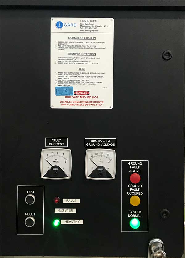
On shore we installed an isolation transformer donated by Olsun Electrics to eliminate stray current and provide an independently derived ground. A high resistance neutral ground resistor donated by i-Gard reduces the arc fault current level (was 20,000+ amps) to a safe for equipment (non-explosive, no arc flash) 5 amps. We added a monitor on the neutral ground resistor to continuously check the resistor and avoid periodic powered off checks (Startco, bought on eBay). We mounted it in the iGard box and added power and fault lights to the i-Gard cover. A sensitive (set to .010 amp) ground fault monitor relay (Bender, bought on eBay) detects ground faults below the levels that are considered dangerous to human life, activates alarms, and a shunt trip breaker. The shunt trip circuit breaker donated by Eaton Cutler Hammer automatically disconnects the shore power in the event of over-current, or ground fault detected by the ground fault relay. The shore power cable plug and receptical was replaced with a new four conductor, switch rated, plug (inlet) and receptical donated by Meltric. This eliminates the need for the separate disconnect switch that was on the pier apron and allowed consolidating separate power and ground cables. The receptacle was also moved 15 foot aft on the pier apron to enable the planned change in location of our brow (gangway used to go to and from the pier.) The heavy service power cable and separate ground cable that run over the brow and are constantly moving was replaced with a new four conductor Type W cable. The 120V non-historic deck light cable running over the brow was eliminated. Note we checked the high pressure air line running over the brow that has metal reinforcement to make sure it is not an un-intended ground. It had 25meg resistance to ground tested with Megger MIT-400 at 500v at the coupling on the pier.
On the boat, hidden under the deck in the superstructure, we added a 480V junction box with two 30 amp 3p, and one 10 amp 1p circuit breakers inside. The shore power goes in, and the ship supply cables leading to after battery out. The center 30 amp, 3p, circuit breaker supplies a welder receptacle on the panel. The right (starbord) 30 amp, 3p, circuit breaker supplies #10-3 marine cable donated by Nexans running to the modern auxiliary hydraulic pump in the pump room (15 HP, 20 full load amps). This eliminated the need to run a portable cord through the visitor path inside the boat from the after battery compartment to the pump room to operate the modern auxiliary hydraulic pump (for example periscope demonstrations.) The receptacle allows welding outside the hull without running a cord over the brow, or through a watertight hatch. The left (port), 10 amp, 1p, circuit breaker supplies a new SolaHD 480V to 120V single phase transformer mounted at the junction. A 20 amp, 30ma ground fault breaker provide by Eaton is on the secondary of the transformer in its own box (port on the panel) supplies a 120V utility GFCI receptacle in a box next at the junction, and a second box with GFCI receptacle hidden by the gun access hatch forward. The box by the gun access hatch also has a Tork timer supplied receptacle for the non-historic deck lights. This eliminates the need for an extension cord run through a hatch for dress lights and work tools. It also eliminated the need for a power cable running over the brow for the non-historic deck lights that was being unplugged every day.
Inside the after battery tank the shore ground wire now goes through a galvanic isolator donated by Dairyland Industries to the 480VAC equipment hull bonding point and hull. This limits small DC stray currents (this is needed because the isolation transformer is mounted on shore instead of on the boat.) Grounding of all equipment housings was completed.
A donated Bender recording insulation monitor was installed on the ship's ungrounded 250 VDC Aux and 115 VDC lighting bus in after battery. It showed 180 kOhms to ground at time of installation, this closely matched Megger readings with the rectifiers and monitors disconnected. We also used a Startco ground fault monitor to directly read the leakage. We were pleased that with normal lighting load there was 11 mA leakage, and with the 250VDC bus closed 18 mA. This is good for a 75 year old system that has never had such sensitive testing tools applied. After isolating some faulty lights the level went up to 680 kOhm. The level varies depending on the weather. We will work to reduce the ground fault level of individual pieces of equipment and the bus as we continue testing.
A Bender recording insulation monitor was installed on the ungrounded output of the 75 kVA transformer that supplies the boat's historic AC MG set circuits, and the modern 40 kVA DC rectifier. It read 440 kOhm when installed with the normal lineup for visitors aboard. The level varies depending on the weather.
A Bender insulation monitor was added to the ungrounded 250 VDC emergency lighting circuit. An isolation transformer was installed to restore an ungrounded (IT) source for the emergency lighting. The insulation monitor read 680 kOhm when installed. The emergency lighting controller was simplified by removing an unused test button timer, DC/AC relay, indicator lights, and associated circuitry.
The three insulation monitors are configured to trip warning indicator lights when any one of the monitors goes below 40 kOhm. We added an indicator light near the crew's head visible to the Pampanito crew while doing their normal safety checks on the boat. There are also indicators in after battery tank, and can be checked over the internet.
Inspired by the networking capability of the insulation monitors we have added WIFI internet access to most of the boat. This allows us to see the monitors while finding ground faults without entering after battery tank, and to see drawings and other reference material from our web site. Kahuna-Fi, Ruckus Networking, Townsend Networks, and Netgate also helped upgrading our internet and WIFI infrastructure on the pier to improve security, speed, and coverage at the same time. We also upgraded the UPS supplying the network gear on shore.
The 480 VAC 3p, fused disconnect that supplies the welder receptacle was re-fused at 30 amps with Mersen fuse reducers. The 60 amp pin lock was replaced with a 30 amp switch rated receptacle for welding projects inside the hull.
The circuit breakers for the modern receptacles in the after battery tank, and hidden next to the scullery sink in the crew's mess were replaced with GFCI breakers.
To improve the safety and efficiency of the power in the shop and work areas on shore we added conduit and receptacles close the locations of the equipment to avoid long extension cords. Vikon Industries and Bay Ship & Yacht ran the conduit and wire that made this possible. Many of the 120v outlets have, or will have their breakers replaced with GFCI breakers. The 208v water heater supply breaker will be replaced with a GFCI breaker. We also will upgrade service where portable heaters are used.
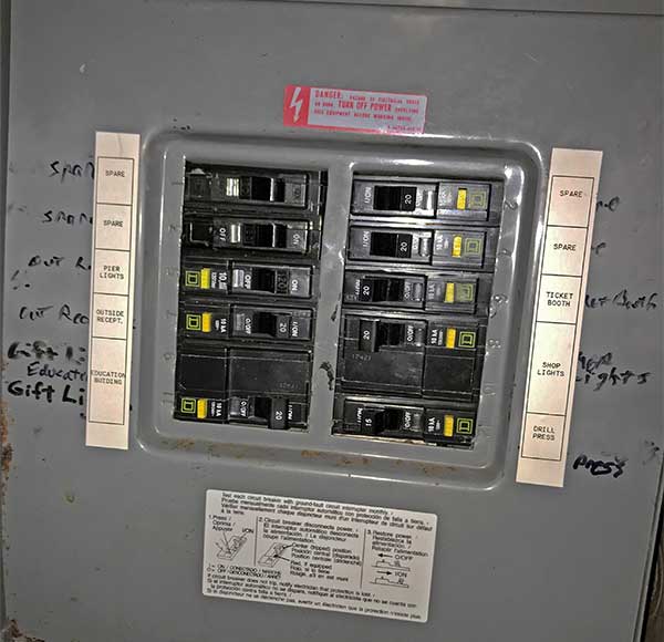
The circuit breakers in the pier apron distribution panel were replaced with GFCI breakers. This includes the ticket booth, education building, shop overhead lights, drill press receptacle, and pier apron lights.
The 480V and 208V three phase welding and machine shop circuits were upgraded to 30 amps with #10 cables, switch rated plugs (Meltric DSN30), 30 amp breakers, and ground fault protection. Conduit was run to switch rated receptacles next to each of the large machines eliminating the need for extension cords. Conduit was run to switch rated receptacles close to the welding work tables to minimize the length of cords. We are considering using a multi-channel ground fault monitor and shunt trip breakers to replace five separate 3-phase GFCIs now in the shop.
All of the work was facilitated by the acquisition of new, really good test instrumentation from Fluke, Megger, Startco, SEL, Ideal. We upgraded many electrical installation tools from Greenlee and Ilsco. A Brady label maker was donated and has been used to label cables and equipment. Separate projects that upgraded our shop and welding infrastructure helped when producing custom mounts, etc.
The first comprehensive drawing of our modern electrical services in the shop, over the brow, and on the boat is being created (mostly done.) A drawing of the ground fault monitoring equipment will be created. A drawing of the revised emergency light controller was created. Additional WW II drawings of the distribution on the boat were found and added to our drawings web page. This note was created to provide an overall view, and will be updated with details of the equipment for easy reference.
Equipment Details:
This section will grow as we complete more of the project.
High resistance ground, neutral ground resistor: i-Gard. Voltage 277V L/N, Current 5 Amps, Ohms 55.4, Duty Continuous, Model SL-277-5/AM/VM/N3R, Serial 48342-1, DWG: 6463. Its controller is currently configured to warn only (it does not trip the shunt trip breaker.)
High resistance ground monitor: Littelfuse Startco. SE-330-00-00 monitor, ER-600VC resistor, ECFT-1 current transformer. These were mounted inside the i-Gard high resistance ground box. We added green unit healthy and red resistor fault indicators to the cover of the i-Gard box. Although we wired the EFCT-1 in, we are not using the ground fault detection capability at this time. It is currently configured to warn only (indicator light).
GF Trip Level 20% (1 Amp for EFTC-1 with its 5 to 0.05 ratio, see tables 1 and 2). Vn Trip Level recommended 60 (table 1), CWB set it at 20. GF Trip Time .01. Pulse 1.0 (we are not using this feature). Switches: S1-K1 Trip Left, S2-Fail-safe Left, S3-Latch GF Left, S4-Latch RF Left, S5-20 ohm Left, S6-60Hz Right, S7-Spare Left, S8-Run Left. Terminals 4-5, SPG are jumpered.
Isolation Transformer: Olsun Electrics. Dry Type Transformer Class AA. kVA 112.5, 3 Phase, 60 Hertz, 4.93 %IZ, 150 deg C temp rise.
H.V. 480 delta 10 KV BIL, 135 Amps.
L.V. 480 wye 10 KV BIL, 135 Aps
Weight 950 lbs, No. A72571, 4/16, GT112.5NO-5-S, 206113-01-01
Pre-installation Megger MIT410, 500V test, 650 meg ohm on secondaries, 1.2 gig ohm on primaries. With Fluke 87, .1 ohm across coils on both primaries and secondaries. Circuit breakers selected for 100amp distribution.
Marine Galvanic Isolater on boat: DEI Marine Fail-Safe Max. GI-100A-FSM. DC isolation, AC coupling. #15009. Failsafe to ABYC A-28. AC 100A continuous. Lightning Current 100kA Crest (4x10 microsecond)
Ground Fault Monitor on 480V shore power: Bender RCM470LY-13A. Current Transformer Bender W1-S35.
480v, 3p, 100 amp, 120v shunt trip breaker for shore side supply: Eaton Cutler Hammer GHB3100S1. The panel is type PRL-2 and uses GB and GHB breakers.
Breakers for welder supply and shop equipment on shore. Cutler-Hammer GHB3030, 30 amp. These will be replaced with GHB3030S1 shunt trip breakers when the opportunity arrises in case we switch to a multi-channel ground fault monitor.
The main 120/208V distribution panel on shore, and the small one in after battery use type BR circuit breakers. The 120/208v distribution panel for the pier apron (store and education) uses type QO circuit breakers.
Transformer under the superstructure: Emerson Appleton, SolaHD, HS5F3AS4X, 3 kVA transformer, 480 V in, 120 out, 1p, encapsulated, stainless steel case, NEMA 4, 4x (wash down), 55 lbs. 6.25 amps in, 25 amps out. Primary 6.25A x 1.6 inrush = 10 amp circuit breaker. Secondary 20a breaker provides 30ma ground fault protection on the cables. 6ma GFCI receptacles protect the portable cords.
Insulation monitor on the 250 VDC Aux power, and 120 VDC lighting bus. Bender Iso685W-D-P, serial 1908529051, Art. No. B91067030W, software D440 V1.30, D439 V1.27. Fuse holders installed in the 150 kVA rectifier disconnect on the DC bus load side contain 2 amp fuses, 18 gauge shielded wire. Close the big rectifier disconnect and start the big rectifier before opening the small rectifier disconnect to access the fuse holder without effecting visitor lighting.
We tested faults on 0, 120 center tap, and 250 VDC successfully. The external test button is on the 120 VDC lighting center tap and has a 2.2 kOhm resistor to ground.
This records time and date of events and works on both energized and de-energized circuits. It also has a networking capability that we may use for remote monitoring in the future.
Set Alarm 1 at 40 kOhm and Alarm 2 at 10 kOhm, external alarm is on alarm 2, normally open. Set to DC IT ungrounded. Ethernet 192.168.1.2, DHCP off, router 192.168.1.1.
Typical value with a normal lighting load for visitors around 680 kOhm.
Insulation monitor for the output of the 75 kVA transformer that supplies the MG Set circuit and the 40 kVA rectifier. Bender Iso685W-D-P, serial 1908529064, Art. No. B91067030W, software D440 V1.30, D439 V1.27. Sensor wire fuse holders (2 amp fuses) are installed on the line input (top) of the MG Set fused disconnect (transformer X1-X2, 0-240 VAC.)
We tested with light bulb faults on x1, x2 and neutral output, all where detected. The external test button has a 2.2 kOhm resistor to ground.
Set at 40 kOhm and 10 kOhm, external alarm is on alarm 2 10 kOhm. Set alarm 2 to normally open. Set to AC IT ungrounded. IP address 192.168.1.3, DHCP off, router 192.168.1.1
Insulation monitor the 250 VDC ungrounded emergency lighting circuit. Bender IR425-D4M1C-2, D231, V1.2. Had 510 kOhm when installed. Tested both energized and de-energized. The external test button has a 2.2 kOhm resistor to ground. Alarms at 40 kOhm and 10 kOhm, alarm contact N/O, 1 second delay.
The insulation monitor indicator in the crew's head uses LED BA9s, 120 VAC bulbs. In the cable the red conductor is common. The black and white are separate for each of the lights. It is configured to display if any of the three monitors trips.
Littelfuse Startco SE-601-OU with SE-GRM250 reference module and PGA-0500 meter for passive, ungrounded, DC, ground fault monitoring. When installed there was about 60% (10 mA) with our normal visitor ready load. Then to 80% (16mA) when 250 bus was closed with no additional equipment operating. This did not detect grounds on the 120VDC center tap.
GFCI on 480V, 3P, GFCI for portable cord receptacles on the 30 amp welding and shop circuit: Bender Lifeguard, LG100-480, 100amp, 77amp motor, 60 hp, trip 6/20mA
240v, 3p, 30 amp, 5ma, GFCI for shop portable cord receptacles: North Shore Safety PGFS-73105. Tests well, but should have been PGFS-83105-138 208v, 30ma GFPD to avoid nuisance trips caused by the welder circuit in the same conduit.
240v, 3p, 30 amp, GFCI: Hubbell GFHW631, 090816 2316, 5ma trip. Had false trips on the 208v from inductive coupling with the welding circuit so it was replaced with a 208V, 30ma GFPD.
208v, 30p, 40 amp, 30ma, GFPD: ABB F204 B-40/0.3 GFPD for the 208v receptacle near the welding table. Note this is supplied by a 30a breaker.
We own, and may use a multi-channel ground fault monitor to replace 5 separate GFCI devices on shore: Bender RCMS490-D-2. We have W1-S35, W2-S70, W3-S105 passive, and W20AB active current transformers, and shunt trip breakers available for installation.
Small Rectifier: Rapid Electric Co. (Now Dynapower)
Serial 1277106, S.O. No. 90120-A
In: 240 VAC, 115 Amps, 60 Hz, 3 phase
Out: 125/250 VDC, 160 Amps, 40 KW, Cont.
Large Rectifier: Rapid Electric Co. (Now Dynapower)
Serial 283611, S.O. C2309B
In: 480 VAC, 200 Amps, 60 Hz, 3 phase
Out: 125/250 VDC, 600 Amps, 150 KW, Cont.
480V, 3P, 100 amp, 4 pole (3p+g), shore power connection: Meltric DSN150 receptacle, 63-94043, 70 deg adapter 89-9A027, 63-98043 plug, handle for old cable 65-9A013-D35 (1.00-1.375), for new cable 65-9A013-D45 (1.375-1.750"), red gasket 31-9AR26. These have an integral disconnect. We removed pilot pins from the donated inlet (plug) on the shore power cable to be compatible with a purchased receptacle we use in the temporary power adapter. Note the Meltric locking rings turn counter-clockwise to remove and the DSLRR wrench is helpful.
Welding and shop tool 480V, 3p+g, 30 amp, #10-4 conductor SOOW cables.
Meltric DSN30 inlet/plug 63-38043 (or 63-38047 with one pin removed, hole plugged). Phase pins are 61-3A011-380, ground pins are 61-3A019.
Meltric receptacle 63-34043, or 63-4047. Note 63-34043-972 with pilot pins will not work, we replaced the interior of a donated -972 with a purchased 61-3A020 spare. Index notch 04 needs to be used for 480v.
Meltric handles 61-3A013 integral .2-.82" cord grip, 61-3A013-34 3/4" NPT, 61-3A013-1 1" NPT. Cord grips from McMaster 69915K55 3/4" NPT .51"-.71" cord, 7529K506 1" NPT 1"-1.1", 69915K71 1" NPT 0.71"-0.98".
Mounting adapters nylon 30 deg 61-3A027, metal 30 deg MA2, metal straight MS2
MB334 3/4" NPT box, or MB31 1" NPT boxes.
We have not used 61-3A426 inlet protective caps, or 61-3A436 finger pads, but they would be protective of the inlets on the extension cords and portable equipment.
Often missing when buying used parts: 61-3AR26 red gaskets, Screws or poly handles/angles #8-15 x 3/4" sheet metal screw, metal accessories use #8-32 x 3/4" machine screws, the metal boxes use #10-32 3/4". MB3G box gasket
Klein 608-3 1/8" 3" cabinet tip screwdriver, Meltric SD18, was worth buying to fit in the DSN30s. DSLRR wrench is nice.
Below is how we wired all our 3 phase cords and receptacles both 480v and 208v:
SO cord black = X = Meltric black = 480v brown T1 = 208v black
SO cord white = Y = Meltric blue = 480v orange T2 = 208v blue
SO cord red = Z = Meltric red = 480v yellow T3= 208v red
Shop tool 208V, 3p+g, 30 amp receptacles, plugs, connectors have been upgraded from L15-30 to Meltric DSN30 63-34163, 63-38163, blue gasket 61-3AB26. These are the same as the DSN30 480V hardware except the index plate is at position 16, gasket is blue, and the labels. The handles, boxes, adapters, etc. are the same as 480V above.
Fuses and box types of modern equipment:
* 250/125 VDC output of 150 kVA rectifier on bus. Box is Siemens F-354 Series A Type 1. Note x2 #2 cable in, x1 #3/0 cable out. 200 A fuses FLSR200-ID
* 250/125 VDC output of 40 kVA rectifier on bus. Box is Siemens F-353 Series A Type 1. 100 A fuses, FLSR100-ID, CRS-R100
* 480 VAC 75 kVA transformer relay. Box is Siemens F-353 Series A Type 1. 60 A, FLSR60-ID. These can be up to 100 A per D. Bonacore.
* 480 VAC supply to 150 kVA rectifier. Box is Siemens F-353 Series A Type 1. 100 A, FLSR60-ID
* 240 VAC supply to 40 kVA rectifier. Box is Siemens F-353 Series A Type 1. 100 A, FLSR100-ID
* 240/120 VAC supply to motor generator switchboard frame 102 (split battery cable). Box is Siemens F-353 Series A Type 1. 100 A FLSR100-ID
* 480 VAC supply to 208/120 9 kVA transformer. Box is Siemens F-351 Series A Type 1. 20 A FLSR20-ID.
* 480V supply to welder receptacle. GE TH3363R Model 10, 100 amp. Mersen Gould 162 or Littelfuse LRU216R reducers to fit 30a fuses in the 100 amp box. 30 A TRS30R
* 480V motor controller for auxiliary hydraulic pump frame 51. Supplied by a 30A breaker at the frame 68 junction. The Allen-Bradly 512-CACD-25 motor controller has W59 19.5A motor overloads (heaters) installed. Control transformer has 6/10 FNM fuse. 40 A TRS40R
* Fused disconnect on portable welder adapter is a Hubbell FDS60, it uses Class "J" fuse. 30 A LPJ-30SP.
* The sensor wires for the SE-601 on DC bus, and IR470LY on MG Set AC, and DC emergency lights have KLKD CC midget 10x38mm 2 amp fuses.
* Pullout fused switch/power receptacle for powerline ethernet is Siemens model WF2030, max 15 amps, ses RK5 fuses.
Kidde i12040A smoke alarm (replaced Oct 2019), with Firex model 0499 Relay Module.
Smoke alarm relay is wired normally open, so if the control power is lost (supplied by the 9 kVA transformer), the 75 kVA transformer the contactor opens.
yellow 0499 -> sensor wire from smoke alarm (green wire in cable, yellow tape)
white 0499 -> white neutral power in, white coil on big relay, white neutral to smoke alarm
black and grey 0499 -> black power in from distribution panel, black power to smoke alarm
red 0499 -> black coil on big relay
In the emergency lighting controller/rectifier/UPS:
* ABB AF09-22-00-13 contactor
* 97F5211S, 1000 VDC, 50 uF GE capacitor
* 52PA4E3 120v ac or dc, 3S6/5 3 watt, S6 screw base lamp, 1/2 candelabra base, indicator light, installed but not in use.
* 52PA4PA 120v ac or dc, neon NE-51H/B2A, 1 pin miniature bayonet, light for top two indicators.
* 5915PC-23T-B30 NMB 230vac 1 phase cooling fan
* FLM 2A control fuses for fan
* KLKD CC midget 10x38mm 2A control fuses for ground fault monitor
* UZ-28, 52-15, 3 inch 15A output fuses.
* AJT20 or LPJ-20SP input fuses
* Unity/I UT4K UPS, Serial UT4K25212, Best Power. 48VDC, 200-240 VAC, 22 amps in, 20 amps out.
* SolaHD HS14F3BS isolation transformer, 3 kVA, 1P, 208 VAC in, 220 VAC out.
All new conduit wire on shore is either XHHW or THHN.
Main shore power cable is type W #2-4 (1.4" dia.)
Cable from junction into after battery is type W #2-3 (1.3" dia) and type W #1 ground (.5" dia.)
Portable cords for welder and machine tools use SOOW #10-4 (.7" dia.)
Marine rated cable under the superstructure is LSTSGU-9 (.55" dia) or Nexans Gexol #10-3 (.50" dia.) The older cables being phased out are SOOW or W.
Note, single phase marine cable uses red for ground.
Monitor sensor wires are 2c, 18 gauge, shielded cable.
Polaris Grey IPLG1-6 and ITG-1 multi-tap insulated connectors on the 480v shore power cable at the junction.
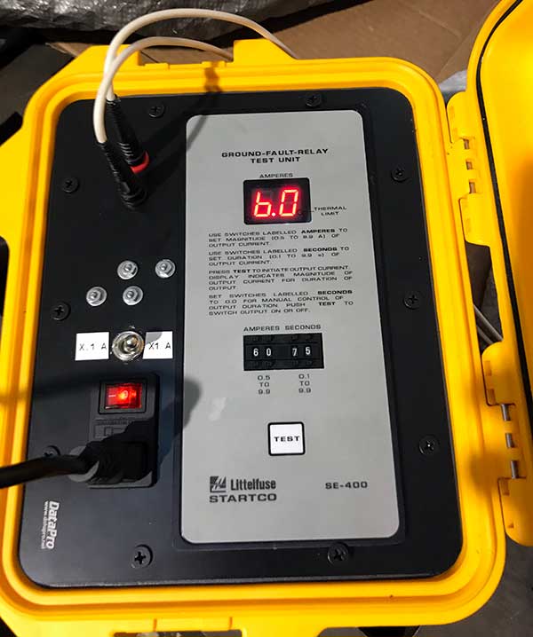
Littelfuse Startco SE-400 ground fault relay tester. We added voltage divider resistors in the case to provide a low current .05 amp to .99 amp. Normal is .5 amp to 9.9 amp. Although rated for .50 amp minimum, it seems to generate a very useful .031 amp when set to 0.04 amp with the divider.
F1 in the bottom of the SE-400 is 1 amp, 1/4" x 1-1/4". F2 inside the SE-400 case is 5mm x 20mm 5MT 100ma. The fuse in the lighted power switch mounted on the bezel is 5mm x 20mm 3 amp.
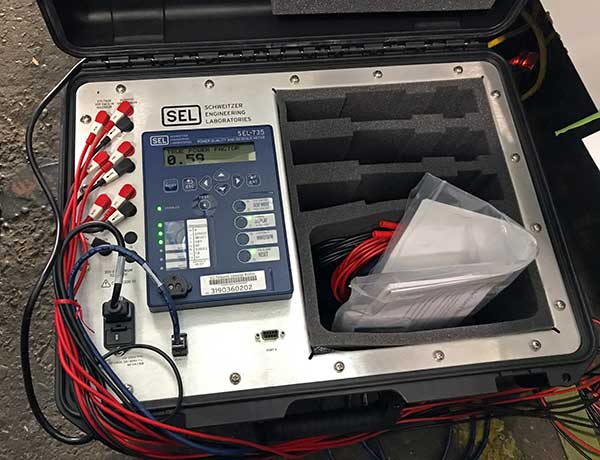
SEL, Schweitzer Engineering Laboratories SEL-735 Portable power quality meter (0735VC20944CXXXXXX16102XX, 3190360202) with x3 1000:5 clamp on current transformers (2" window, 1% accuracy.) We are using this for power quality event recording voltage, sag, swell, interruption (VSSI), flicker, blink, power factor, etc.
Ruckus 9U1-R710-US00 smart mesh WIFI network access point with Unleashed management
Ruckus 9U1-R610-US00 smart mesh WIFI access points
Ruckus 9U1-T310-US51 120deg sector smart mesh outdoor WIFI access point
Ruckus 901-T300-WW01 smart mesh outdoor WIFI access point
Ruckus ICX-7150-C08P - 8 port PoE+ switch
Ruckus ICX-7150-C12P-2X1G - 12 port PoE+ switch
Ruckus 902-0162-US00 - PoE injectors
Ruckus 902-0183-0000 M2.5-1.5 cable gland with split ferrel for T300 and T310
TP Link PoE switch TL-SF1005P 100 mbs PoE
TP Link PoE switch TL-SG1005P 1 gbs PoE
Netgear GS305PP-100NAS 1gbs, PoE+ switch
Netgate SG-1100 router with pfSense software
APC SMT-1500 UPS in copier room
APC BE850M2 UPS in triangle space
Acknowledgements and Thanks:
We appreciate the advice, help, donations, and discounted products and services from individuals and companies along the way. We had the help of an very talented team. We could not have succeeded without the incredible generosity of these people and companies:
ADVICE AND HELP:
Charlie Butcher
Len Vaden
Rich Brown
Dominick Boncore
Vernon Vanderpool
John A Cherry
Mike Wade
USN USS Cable Reserve Det 220 during the 1990s
Rich Pekelney
Volunteers and staff of USS Pampanito
DONORS:
Alameda Electric Distributors, discount electrical supplies, https://www.alamedaelectric.com/
ABB, ground fault protection device, https://abb.com
B.R. Rosenblatt & Associates, engineering, http://brosenblatt.com
Bbrozelco, plug, http://www.brozelco.com
Bay Ship & Yacht, conduit installation, waterjet cutting, https://www.bay-ship.com
Bayshore Metals, steel for foundations, http://www.bayshoremetals.com
Bender GmbH & Co., insulation monitors, https://www.benderinc.com
Brady Worldwide Inc., label maker, https://www.bradyid.com
Cereske Electric Cable Co., discount electrical wire and cable, http://www.cereske-electric.com
Control Stuff, Inc, junction box, http://www.controlstuff.com
D & F Liquidators, boxes, conduit accessories, https://www.dfliq.net
Dairyland Electrical Industries, galvanic isolator, http://www.deimarine.com
Denso North America, Densyl tape, http://densona.com
Eaton Cutler-Hammer, circuit breakers, http://www.cutlerhammer.com/
eBay 756wire, circuit breakers
eBay abushareef, Meltric handle
eBay ace-voltage, boxes
eBay arcticcirclesurplus907, circuit breakers
eBay bailey2, strain relief cord grips
eBay asisurplus, circuit breakers
eBay bill_edwards, current transformer
eBay bigavsound, plug, handles, adapter at discount
eBay brozelco, plug
eBay bustersbz, plug with handle
eBay carwashparts, junction box
eBay cfi.industrial, fuses
eBay chafebm, crimper
eBay chrus-qf6twh, discount on connector
eBay dbray71pb, Meltric inlet
eBay dickplato, fuses and fuse reducers
eBay electricaljunkman, receptacle and handle
eBay emmypei, switches and mounts
eBay equipmatsales, receptacle, cover, box
eBay freedom*resources, buttons
eBay gksurplus, current transformers
eBay glb_industrial, plugs
eBay industrialpartsrusinc, circuit breakers
eBay jj*industrial, receptacle mount
eBay interlab, current transformer
eBay jbjornj, receptacle
eBay jlsmiley79, receptacles
eBay kengill11, switches
eBay limpet555, button station
eBay Lowellfisherman, current transformers
eBay mandygillum4, adapter plates
eBay midwestsemi, discount on current transformer
eBay motors-controls, circuit breakers
eBay premiumcablesandmore, sheilded signal cable, Gexol cable
eBay rit4u-2010, GFCI circuit breakers
eBay rjs_electronics, indicator lights
eBay s_jones, receptacle cover
eBay sigmapackaging, latches
eBay simpsonvilleindustrial, handles
eBay sonicent-2008, GFCI receptacle
eBay surplushouse, junction box back panel
eBay surplus_liquidation_center, junction box back panel
eBay swvasurplus, circuit breaker
eBay tcb3162, discounts on plugs and receptacles
eBay wickedtsi, receptacle with handle
Emerson SolaHD, transformer,http://solahd.com
Ethos Dynamics, WIFI access point, https://ethosdynamics.com
Fluke, Fluke and Amprobe meters, http://en-us.fluke.com
General Cable, electrical cable, https://generalcable.com
Greenlee, tools, https://www.greenlee.com
Hammond Mfg. Co., knockout plugs, https://www.hammfg.com
Hubbell, plugs, receptacles, disconnect, https://www.hubbell.com
Ideal Industries, Suretest circuit analyser, http://www.idealind.com
i-Gard, high resistance ground, http://i-gard.com
Ilsco, Taskmaster 3in1 and pigtail adapters, http://www.ilsco.com
Kahuna-Fi, network design, https://www.kahuna-fi.com
Lewis Motor Repair, ground fault monitor, http://lewismotorrepair.com
Littelfuse, Startco, DC ground fault monitor & fuse accessories, https://www.littelfuse.com
LiveWire Electrical Supply, circuit breakers, https://livewiresupply.com
Manson Construction, funding, GFCI, cable, http://www.mansonconstruction.com
Megger, meter, https://us.megger.com
Meltric, plug and receptacle, http://www.meltric.com
Mersen, fuse reducers, http://ep-us.mersen.com
Netgate, router support, https://www.netgate.com
Nexans AmerCable, Gexol marine cable, https://amercable.nexans.com/en/
Norbert Vrabel, kellems wire puller, Union City, CA
North Shore Safety, 250VAC GFCI, http://www.nssltd.com
NSi Industries, Polaris connectors and other parts, http://www.nsiindustries.com
Olsun Electrics Corporation, isolation transformer, http://www.olsun.com/
Remke, cord grips, http://www.remke.com
Rowmark, laser engravable plastic label stock, http://rowmark.com
Ruckus Network, WIFI network equipment, https://www.ruckusnetworks.com
SEL, Schweitzer Engineering Laboratories, power quality meter, https://selinc.com/
Rich Pekelney, numerous parts, San Francisco, CA
Pio's Trucking Inc, custom frame fabrication, Richmond, CA
Townsend Neworks, wifi access points, https://www.townsendassets.com
Photos:
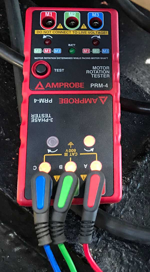
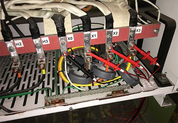
Feb 2018. Before installation we documented with photos the phase relationship inside the boat so we can make sure it is the same at the end.
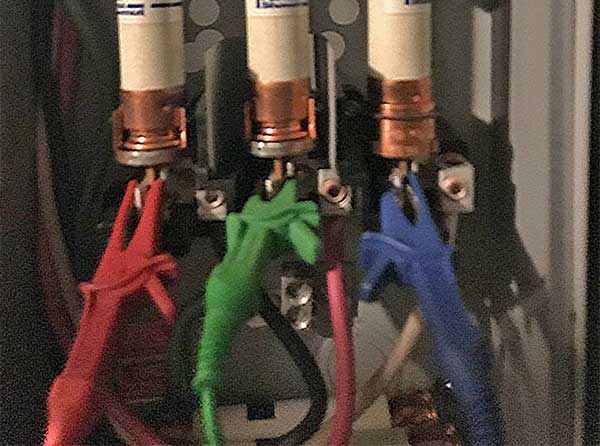
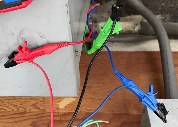
Feb 2018. We use the welder receptacle switched disconnect in after battery (formerly hydraulic pump supply) as a convenient place to attach the leads. Note the modern auxiliary hydraulic pump is the only 3 phase rotary device on the boat. The historic equipment is DC, or single phase AC.
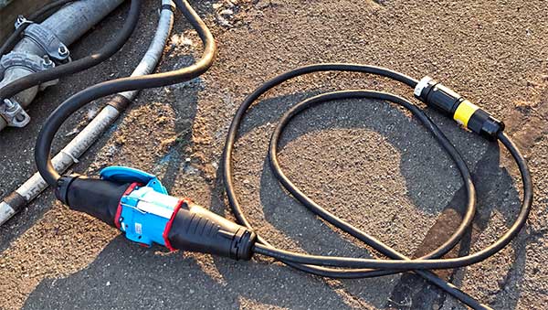
Feb 2018. We shifted from normal shore power to our welder supply using this Meltric DSN150 to Hubbell 50 amp twist lock adapter (later changed to Meltric DSN30.) We used Checkers FL1X4-O cord protectors across the pier apron. This allowed us to keep the boat open to visitors during the installation. At the end of the work we closed the boat for about 15 minutes to shift to the new supply and check/correct the phase relationship.
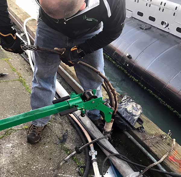
Feb 2018. We removed the old junction boxes inside the shop and on the pier apron first. The next step was pulling the old, cloth insulated wire that filled the conduit. We used a Greenlee Kellums wire grip to connect to the wire.
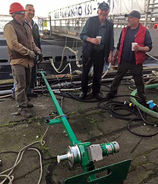
Feb 2018. Greenlee brought a truck full of tools and trainer to help. We started the first wire with the puller, then used the truck. We were relieved when the wires that were tight in the old conduit pulled with no problems.
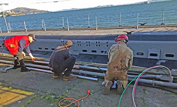
Feb 2018. The new wire has been pulled. The crew is installing a 2" conduit extension about 15 foot aft. This is needed to make room for a planned future move of the brow (the gangway that is used to get on/off the boat) when the 5" deck gun is moved aft.
Feb 2018. Inside the shore connection box. The wires come in the bottom from the shop, the wires go on top to the Meltric receptacle. The separate ground wire from the boat comes in through the bronze bolt at the bottom. When we replace the 3 conductor shore power cable with a 4 conductor cable it will come through the receptacle.
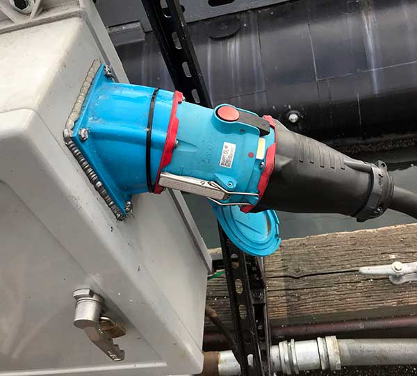
Jul 2018. Meltric integral switch disconnect receptacle on the shore power cable. To remove, you push the red button, the inlet (plug) pops out a bit and the connections are broken, then you rotate the inlet to match the red dots before full removal. It is simpler to do than describe, but is safer to use than the old connectors.
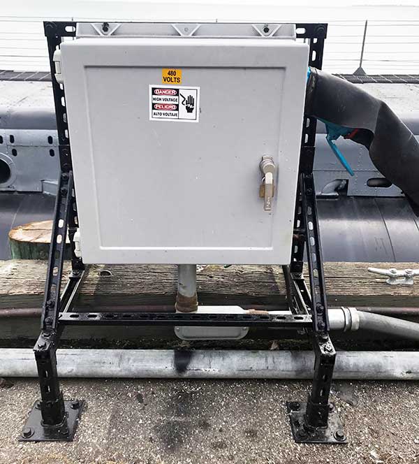
Jul 2018. Completed pier junction box.
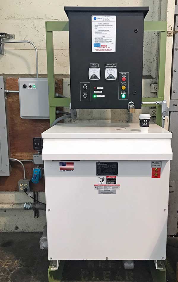
Feb 2018. The Olsun isolation transformer and i-Gard high resistance ground were pre-mounted on the custom frame, and as much as possible was pre-wired before installation day. However it could not be moved and bolted in place until the old connection box was removed and the new wire pulled. There was still a lot of hard work to fit and install conduit and wire on installation day.
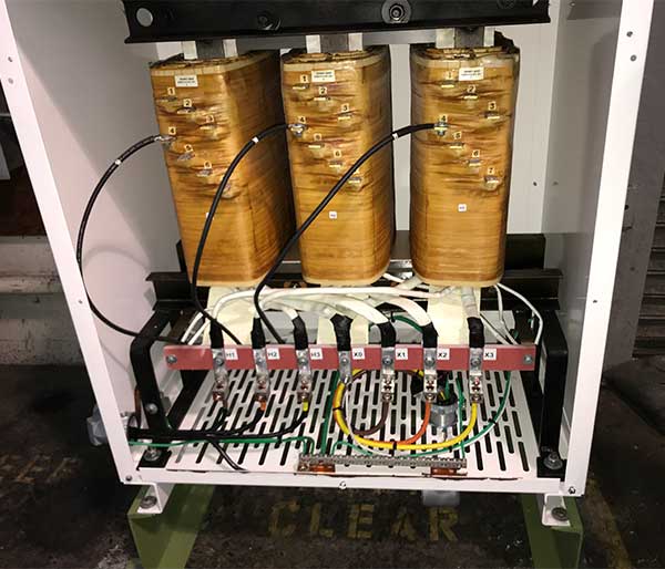
Feb 2018. Inside the isolation transformer after power up testing. You can see the taps have been changed to position 4 to bring the voltage to 480VAC.
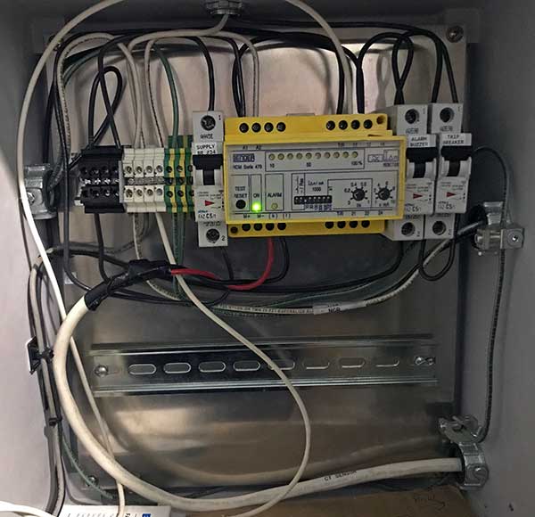
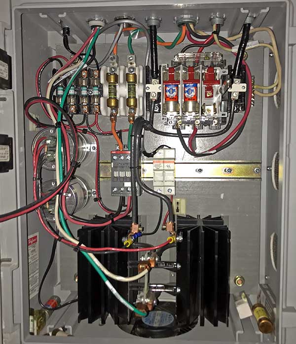
Feb 2018. The ground fault monitor, current transformer, and alarms were pre-wired before installation day. The conduit and connections from the 120VAC control power, to the shunt trip circuit breaker, and control power to the high resistance ground had to be done day of installation. The left breaker is control power, ground fault monitor in the middle, then the audible alarm cutout, finally on the right the shunt trip breaker cutout.
Feb 2018. Inside the i-Gard high resistance ground you can see the 55.4 ohm resistor on top. On the bottom right, the white wire is neutral from the isolation transformer (X0), and the green wire is ground. The sensitive control relay and current transformer are for the alarms.
Feb 2018. Final testing. The white wire was temporarily looped through the current transformer. A small current was run through it to simulate a ground fault. The ground fault monitor detected it, presented visual & audible alarms, and tripped the shunt trip breaker. Next, the brown jumper wire with yellow clips was purposely attached between one phase of power and ground simulating a hard ground on the 100amp circuit.
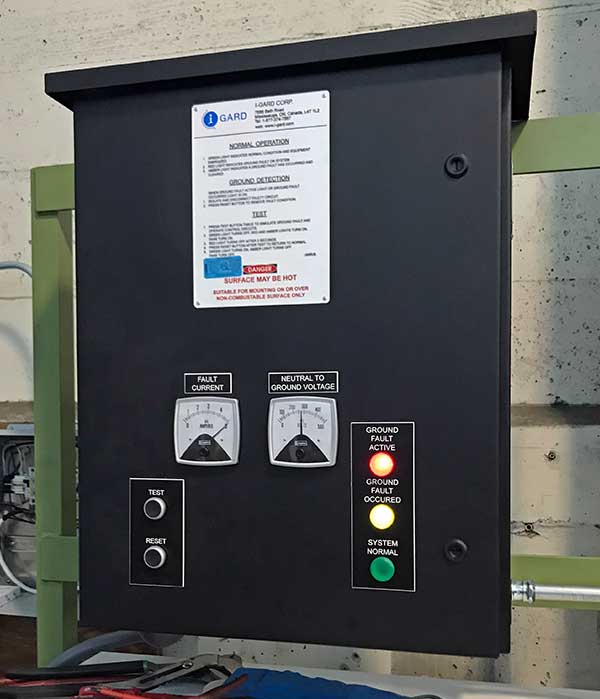
Feb 2018. When power was restored with the ground fault in place, the resistor limited the ground fault to 5 amps (left meter). The right meter shows 277 volts. The Active Ground Fault, and Ground Fault Occurred indicator lights are lit, the fan came on. What did not happen was the vaporization of the jumper clip or explosion. This was a powerful demonstration of just how much safer the power supply is. Finally we shifted the boat onto the infrastructure and adjusted phase relationship. The monitor was tested at 10ma. For a couple of weeks we left it at 30ma and then changed it to 10ma for long term. We also test forced a solid ground on the boat with the same safe response.
Jul 2018. We later added an SE-330-00-00 monitor, ER-600VC resistor, ECFT-1 current transformer in the bottom of the high resistance ground box. These check the health of the ground resistor and take the place of a periodic powered down check of the resistor. The device has a ground fault detection capability, but it is not currently used. Note some models of high resistance ground systems have the resistor monitoring built in.
Jul 2018. The i-Gard cover has had two indicator lights for the SE-330-00-00 monitor. If a problem arose with the i-Gard resistor, the red Resistor Fault indicator will light.
Jul 2018. The shore power supply completed.
Dec 2018. We acquired and mounted in a portable case this ground fault test unit (Startco SE-400.) The test lead is passed through the ground fault current transformer. When the test button is pressed a current flows through the leads to simulate a ground fault and test the ground fault monitor. We added a switch for normal (x1 amps), and through a voltage divider low (x.01 amps).
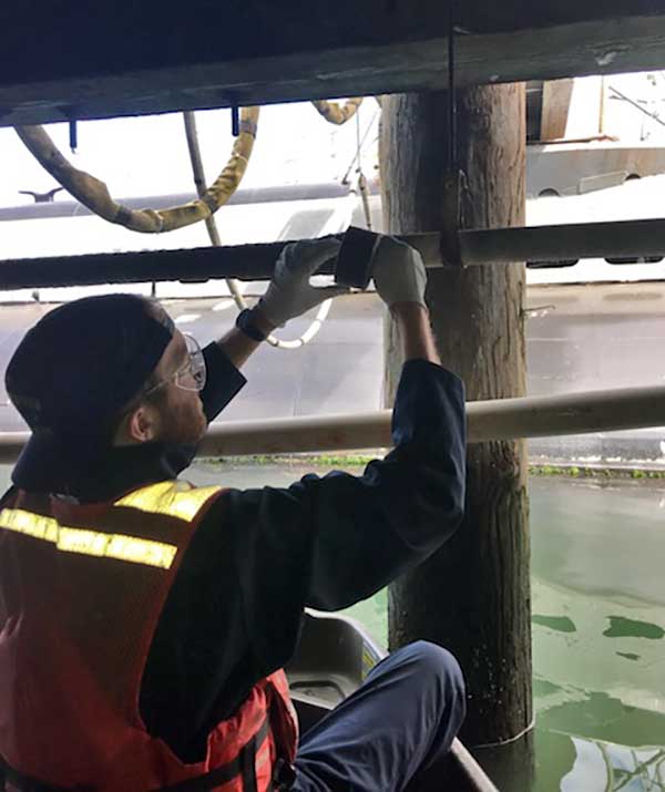
Feb 2018. Crew members Dylan and Javier wrapped the rusty parts of the 2" conduit running under the pier with Denso Densyl tape. This product has not changed since first created in 1929, older than Pampanito. Later some of the galvanized hangers were replaced.
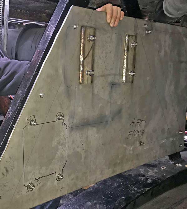
Aug 2018. Test fit of shore power junction panel under the deck. Bayshore Metals donated the 316 stainless steel panel. Nelson Stud Welding donated an N600i welder and the 18-8 stainless steel normal and stand off studs. This was our first project using the stud welder and were delighted how fast and easy the 29 studs installed. We will use more when we dress out all the cables.
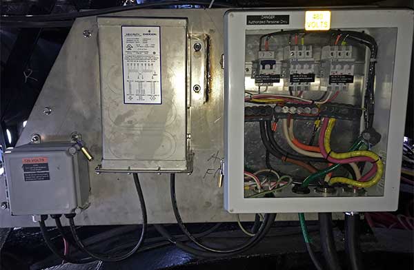
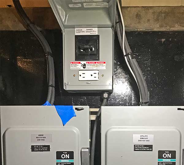
Aug 2018. The shore power cable feeds this new junction panel hidden under the deck at frame 68. A 3c cable and ground wire from here go through a salvage valve into after battery where most of the museum era electrical infrastructure is located. A 480v 1p circuit breaker supplies the transformer in the middle. This transformer supplies 120v to the GFCI circuit breaker on the left. That breaker supplies the receptacle on the other side of the panel and next to the gun access trunk. A 480v 3p breaker supplies a cable to the modern auxiliary hydraulic pump in the pump room. Finally there is 480v 3p breaker that supplies a welding receptacle on the other side of the panel.
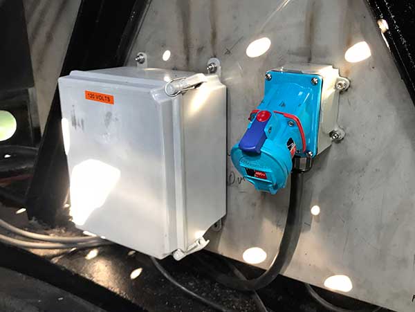
Aug 2018. 120v receptacle (in the box), and 480v receptacle hidden under the deck at frame 68 (opposite side of the panel above.)
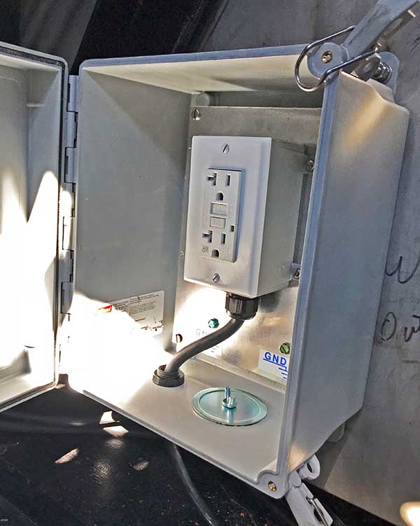
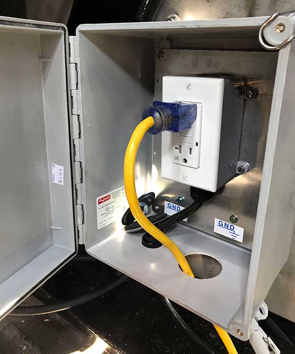
Aug 2018. 120V receptacle at the junction in a waterproof box. The 2" hole in the bottom has a knock out plug installed when not in use.
Aug 2018. 120V receptacle at the junction with a portable cord in use. The door is only open for the photo, it is normally left closed.
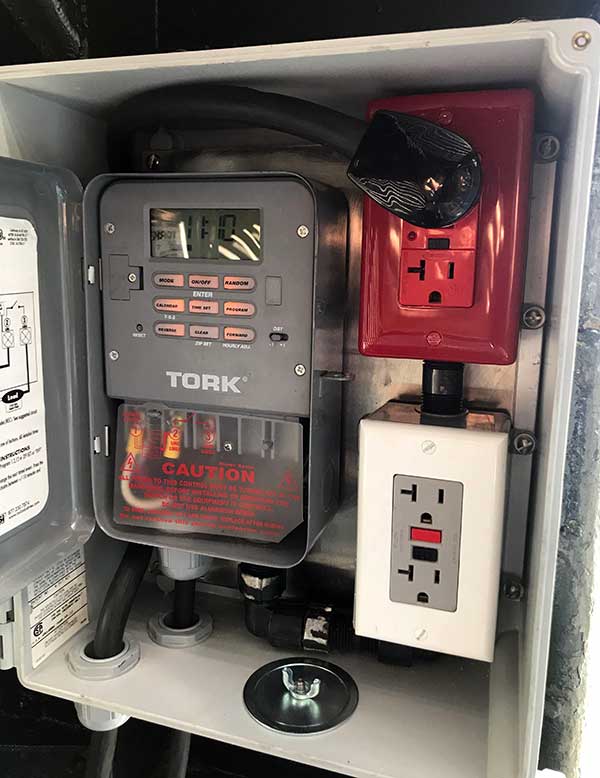
Aug 2018. 120V receptacles hidden at the gun access trunk. The Tork timer controls the red GFCI receptacle. The non-historic deck lights are plugged into the timer. The grey GFCI receptacle is for work tools. Holidays lights can be supplied from this box eliminating the need for a cord through the conning tower hatch. Note the 2" hole in the bottom for portable cords. The box is kept closed except when installing or removing cords.
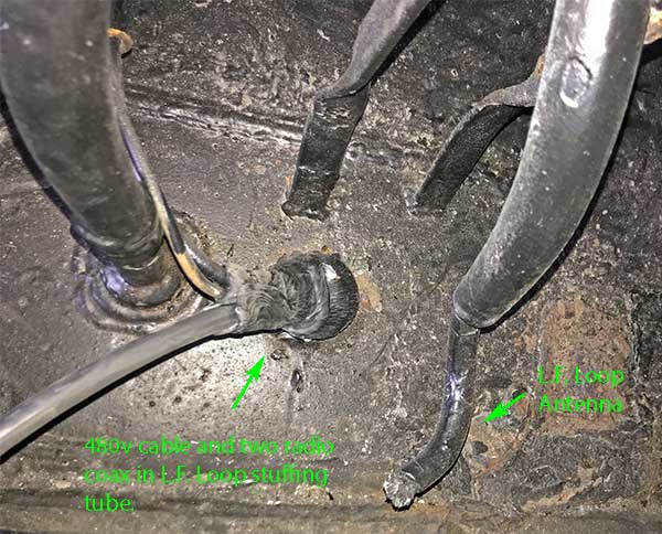
Aug 2018. Center is the stuffing tube that originally contained the low frequency loop antenna cable. Just aft of Frame 68, above the TBL radio in radio room. Sometime in the 1980s the original two wire cable was removed and the two coax cables installed by amateur radio enthusiasts (hams). We added the 480v cable from the junction that leads to the modern auxiliary hydraulic pump in the pump room.
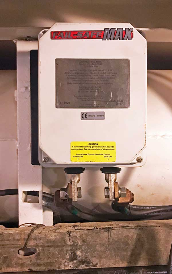
Feb 2018. DEI Fail-Safe Max galvanic isolator installed on a custom bracket in after battery tank. This limits small DC currents on the shore ground wire.
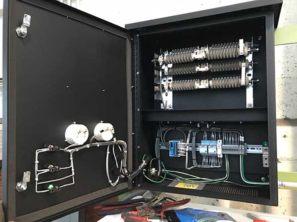
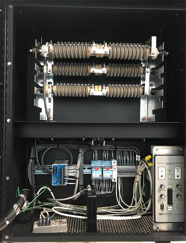
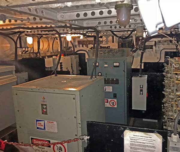
Aug 2018. Modern equipment installed in after battery.
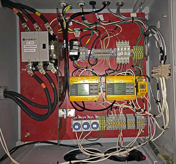
Oct 2019. Insulation monitors in after battery tank.
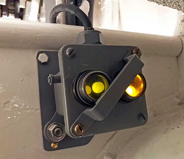
Oct 2019. Monitor warning indicator added in the crew's head above the sinks. This is easily visible to our crew while doing their safety walk throughs. The custom mounting bracket was designed to mount the indicator without any new holes in the historic fabric.
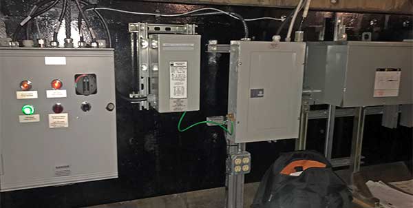
Sep 2019. Modern equipment added inside after battery from left to right. Emergency light controller, emergency light isolation transformer, utility power distribution panel, utility power 9 kVA transformer.
Dec 2019. Inside emergency light controller after simplification.
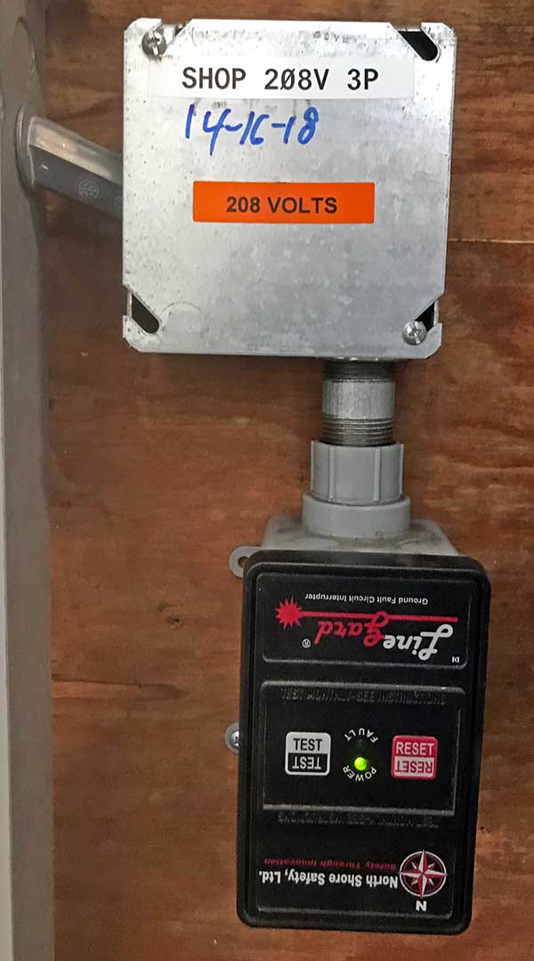
Jul 2019. North Shore Safety PGFS-73105 GFCI protection on the 208 VAC, 3-phase supply to the machine shop receptacles. These are used for the cold saw, blast cabinet dust collector, and disc sander.
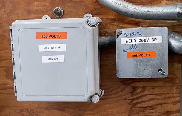
Jul 2021. ABB F204 B-40/0.3 GFP protection for the 208 VAC, 3-phase supply to the receptacle at the welding table in a Hoffman enclosure. This is used mostly with the the hydraulic bender.
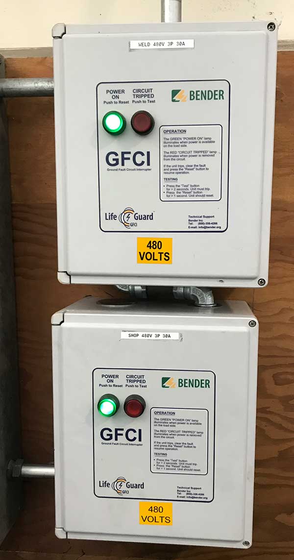
Jul 2019. GFCI protection for the 480 VAC, 3-phase receptacles. Used with the welder, plasma cutter, lathe, mill, and vertical band saw.
Jul 2019. Note the Meltric DSN30 480 VAC on the left has red gaskets in addition to labels, the Meltric DSN30 208 VAC on the right has blue gaskets. The cords are keyed so one cannot accidentally plug into the wrong voltage. Pushing the button opens the fully rated disconnect. Turn to the left until the dots line up and the pull to remove.
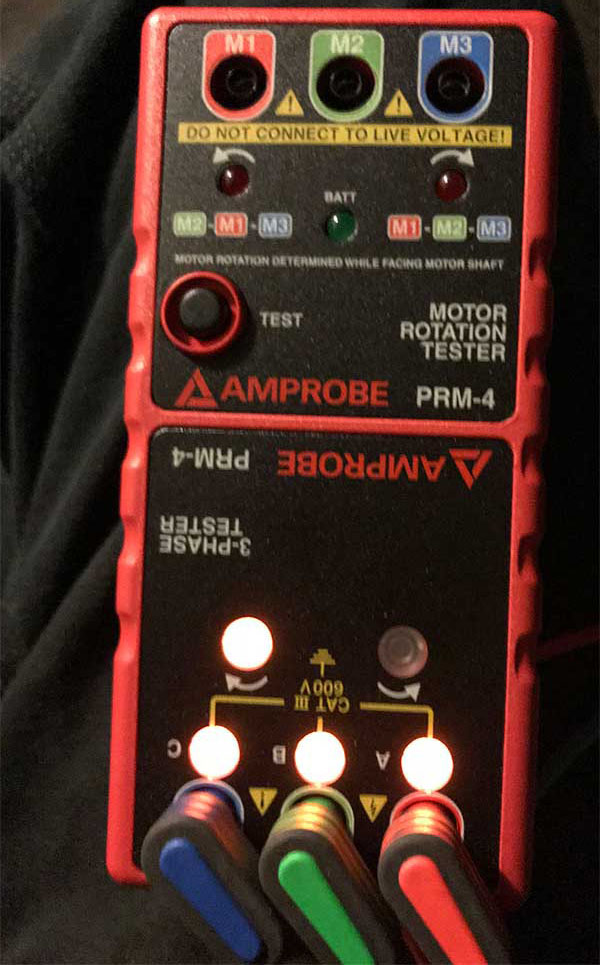
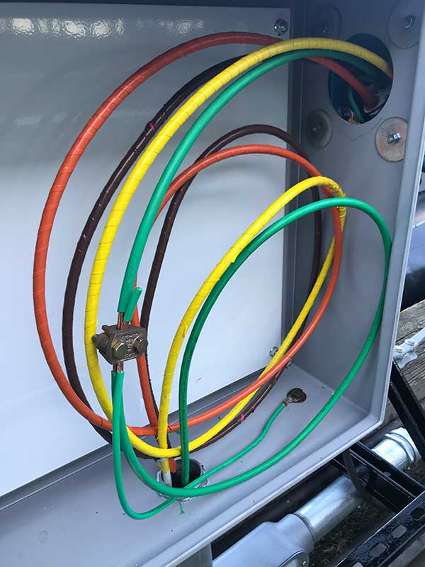
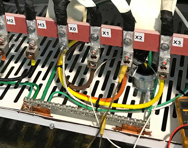
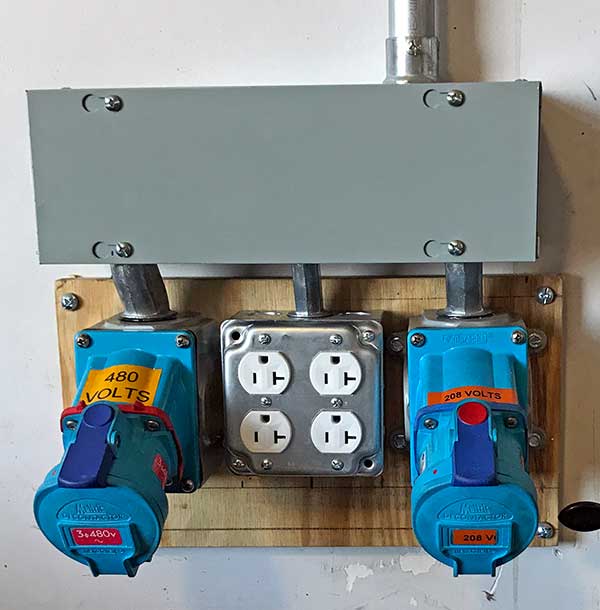
Aug 2018. All the 480V 3-phase, DSN30 receptacles have the same phase relationship as documented here.
Aug 2018. The colored wires match the DSN30 inlet colors. This photos shows the clips from the phase meter in the photo above.
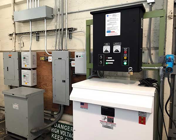
Jul 2019. Shore side distribution center.
Oct 2018. Pier apron distribution panel with GFCI breakers installed. We also used the new Brady label maker for the first time.
Feb 2019. SEL-735 power meter. We use this to diagnose power problems from the Port of San Francisco, or in our infrastructure that supplies the boat. We discovered an inefficient .59 power factor on the first test. VSSI was better than we thought. It came in the portable case.
Oct 2019. The SEL-735 measures voltage on the clip leads, and current with the clamp on current transformers.
Sep 2020. Pullout switch/power outlet added to MG Set Utility Circuit to supply powerline ethernet in after battery.

