The Mark 18 torpedo is electrically propelled by means of a direct-current motor, supplied from storage batteries contained in the torpedo. This motor, which provides the mechanical energy to turn the propellers, is started by the closing of a switch which permits electric current to flow through the motor field coils and armature coils causing rotation of the armature, which is transmitted by means of a shaft to the propellers. At the end of an exercise run this switch also interrupts the supply of electrical energy to the motor causing it to stop. The motor speed is regulated by means of a governor which tends to hold the speed constant by shifting the motor brushes to such new positions that the motor will draw more current as the voltage of the battery decreases during the run. This governor consists of a mechanism directly geared to the motor shaft and responds to any reduction in speed and tends to keep the motor output constant.
Type and Description.
The type of motor used in the Mark 18 torpedo is known as a 6-pole, direct-current series electric motor. It should be noted at this point, that when the load of a series motor decreases the speed increases, and when the load becomes very small the speed rises to such a point that there is danger of the machine wrecking itself. For this reason the motor should never be run at normal voltage when not under full load. Proper test voltages will be discussed later. Series wound motors are capable of starting under heavy loads and are inherently a constant horsepower machine, since as the torque increases with an increase in current, the speed decreases.
The motor is composed of the following main parts:
1. Frame and field.
2. Armature.
3. Commutator.
4. Rocker ring assembly.
5. Bearings.
Frame.
The frame serves as part of the magnetic circuit so that the necessary flux may be provided at the air gap between the pole faces and the armature and also forms a housing for the armature and a support for the bearings. The frame is rolled from a strip of rolled steel with the ends welded together. On the inside of the frame are mounted inwardly projecting parts known as poles.
These poles, six in number, are made from laminated punchings- pressed and riveted together to insure rigidity. Two holes are drilled and tapped to permit securing the poles to the frame. The poles are so mounted as to provide an air gap of 3/16-inch between the pole faces and the armature and to support the series field windings.
Series Field Coils.
The series field coils are made from copper strap 0.109 by 0.875 inch which is wound about a form using a layer of asbestos tape between turns, after which they are placed in a curved mold and pressed into shape to fit inside the frame assembly. After shaping, the coils are taped and impregnated with an insulating varnish and baked. When mounted on the frame, springs are inserted between the coils and frame to assist in holding them rigidly in position. The field coils are then connected electrically in series by brazing copper straps between the coil leads. A special flux, called silfos, is used for brazing which is done with an electrical resistance heater. The field
79
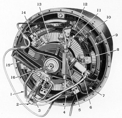
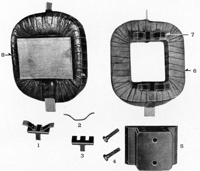
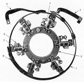
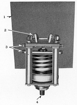
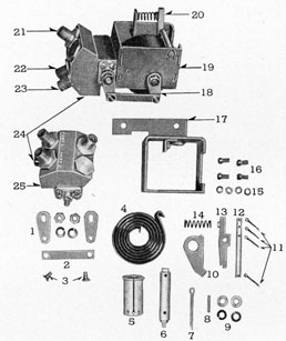
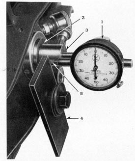
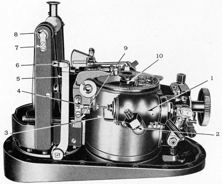
FIGURE 63-6.-Motor forward end.
LEGEND
1-Governor.
2-Oil lead from reservoir.
3-Oil lead to power piston.
4-Connector rings.
5-Oil reservoir.
6-Power piston.
7-Front end bracket.
8-Field coil.
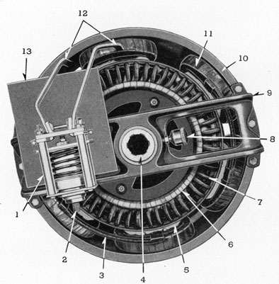
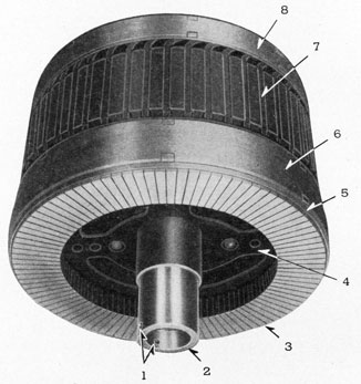
1-Starting switch.
2-Air connection.
3-Connecting strap.
4-Rear view of motor shaft.
5-Pole face.
6-Supporting ring for armature coils.
7-Armature coil-rear view.
8-Grease cup.
9-Rear end bracket.
10-Frame.
11-Field coil.
12-Connecting straps to switch brazed to field coils.
13-Micarta-asbestos arc shield.
81
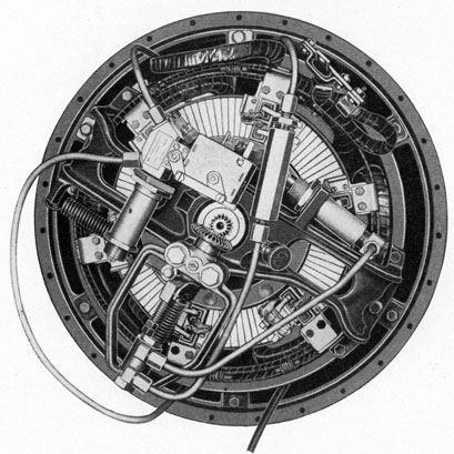
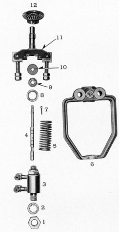
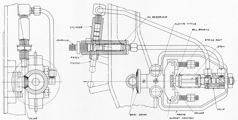
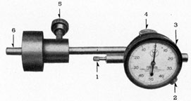
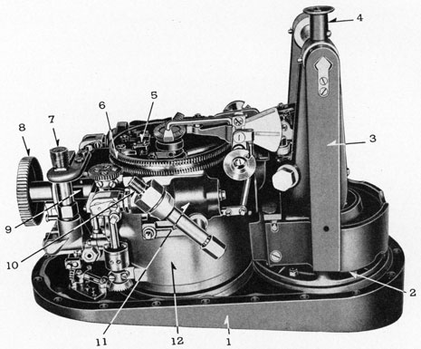
FIGURE 65-6.-Motor in afterbody, showing 4-way valve, governor, relief valve, power piston, oil reservoir.
82
coil insulation must stand an electrical test of 2,000 volts between coil windings and frame for 2-3 seconds. The field coils are connected so that every other pole is north thus giving 3 north and 3 south poles.
Armature.
The armature is the rotating part of the motor and consists of the armature core, coils, commutator, and shaft.
Armature Core.
The armature core is made from thin laminations or punchings from silicon steel, which are carefully stacked with match marks uniform so as to keep the burrs of the stampings all on the same side and thus reduce the air gap between laminations. The core is slotted to provide
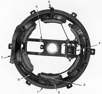
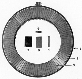
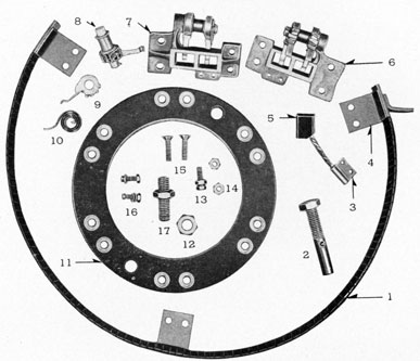
FIGURE 66-6.-Motor Frame.
LEGEND
1-Frame.
2-Field coil.
3-Pole.
4-Starting switch.
5-Terminal.
6-Rear end bracket.
7-Flexible lead.
8-Connecting straps-Cross connectors.
better mechanical protection for the windings and reduce the length of the air gap between the pole faces, the windings, and the core. The core is made up of 0.018-inch laminations in the center with two 0.028-inch laminations on each outer side. These laminations contain 50 slots designed to take two coils each.
After the laminations are stacked, a spider is placed on each outer side of the core and a pressure of 75 tons is exerted on the laminations, after which rivets are pressed into the spider
83
and core at 25 tons pressure. Gusset plates are inserted into the core and welded to the spider to give rigidity. The outside diameter of the core is 12 inches. The core assembly is then pressed on the shaft and welded into position.
Commutator.
The commutator is a means for reversing the connections to the armature coils at the proper instant during the rotation of the armature. This results in a reversal of the flow of current in the coils which is necessary, as they move under the poles of opposite polarity, in order to cause continuous rotation.
The commutator is made up of 100 copper segments or bars, wedge shaped, with a slot at one end to receive the coil leads. The segments are assembled in a jig with metal spacers
FIGURE 67-6.-Field coil.
LEGEND
1-Springclip assembly.
2-Spring.
3-Clip.
4-Bolt.
5-Pole.
6-Field coil before impregnating.
7-Spring clip in position.
8-Pole in place in coil.
between (later, these spacers are replaced by mica) clamped in position on the jig and mounted on the motor shaft, in position for winding the armature. As the armature is wound a piece of silfos ribbon is put in the segment slot before the coil ends are driven into the slot to insure a good contact between the coil ends and the segments when the connections are brazed; after brazing the clamp is removed and the metal spacers replaced by mica strips which have been previously dipped in impregnating compound. A heavy clamp is placed around the commutator and the segments drawn up tight against a wooden disk and then baked to form a solid unit.
84
FIGURE 68-6.-Armature.
LEGEND
1-Setscrew holes for pinion gear.
2-Shaft.
3-Commutator bar.
4-Spider.
5-Insulation beneath banding.
6-Banding.
7-Coil in slot.
8-Banding.
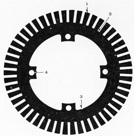
FIGURE 69-6.-Armature lamination.
LEGEND
1-Teeth.
2-Slot.
3-Match marks for proper stacking.
4-Hole for rivet.
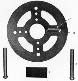
FIGURE 70-6.-Armature spider.
LEGEND
1-Gussett.
2-Rivet.
3-Spider.
4-Position of gusset on spider.
85
FIGURE 71-6.-Commutator
LEGEND
1-Jig used during construction.
2-Front view of commutator bar.
3-Mica insulation between bars.
4-Rear view of commutator bar.
5-Side view of commutator bar.
6-End view of commutator bar.
7-Mica insulation used between bars.
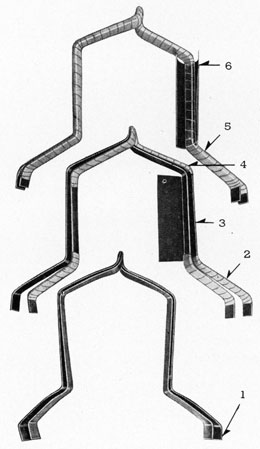
FIGURE 72-6.-Armature winding
LEGEND
1-Coil lead to commutator segment.
2-Tape, lap.
3-Fishpaper and mica.
4-Tape.
5-Tape.
6-Fishpaper used when inserting coil in core slot.
86
The armature is then dipped and the circumference of the commutator faced and banded. The armature is then baked, after which the face of the commutator is machined, the mica undercut and commutator given a final polish.
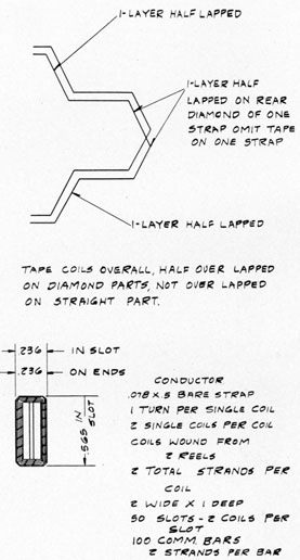
Armature Coils.
The armature coils which make up the rotating electrical circuit of the motor are made from 0.078 by 0.5-inch copper strap formed in molds by hand. There are two straps per coil. The
FIGURE 73-6.-Motor armature coil and coil gauge.
straps are first insulated from each other with cotton tape except that on the commutator connections glass tape is used. A fishpaper and mica wrapper is placed between and around the two straps where they are in the armature slots. They are then lapped, not overlapped on the straight part but half lapped on the rest of the coil, using cotton tape except on the commutator leads where glass tape is used. The cells are lined with fishpaper before the coils are put in
87
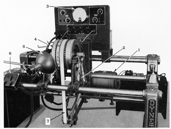
FIGURE 74-6.-Armature balancing machine
LEGEND
1-Driving motor.
2-Brake.
3-Dial.
4-Armature to be balanced.
5-Stroboscope.
6-Controls.
7-Driving belt.
88
place. The top and bottom commutator end connections are separated by glass tape. The rear end connections are banded down against an insulated ring.
After winding, but before brazing, the coils are tested to ground, at 2,000 volts momentarily and 1,500 volts for 1 minute.
The coils are located in the armature and connected to the commutator bars as follows: Place a pencil in the slot, on the core, in which it will line up with the insulation between commutator segments. There are several points about the periphery where this will occur. Place a punch mark on the first bar to the right of the insulation and call this bar No. 11. Count clockwise facing commutator until No. 1 bar is reached (10 bars away). Place right-hand end of coil in bottom of slot in this No. 1 bar. Then count from No. 1 bar, counterclockwise, to No. 34 bar to which the other end of the coil is to be connected.
5-Flexible lead.
6-Brush terminal.
7-Brush in holder.
8-Spacer.
Rocker-Ring Assembly.
The rocker ring assembly is mounted on the commutator side of the motor and consists of the following parts:
1. Micarta ring.
2. Brush-holders and brushes.
3. Connector rings.
4. Speed control pin.
5. Spring connection.
The micarta ring provides a support for the brush-holders and is mounted on the front end-bracket so that it can be rotated freely,
89
Brush Holders.
The brush-holders are bolted to the micarta ring and care should be taken that an electrical clearance of at least 1/8 inch is maintained between brush-holders and end-bracket. The brushes are held in position in the holders by means of springs which are adjusted to give a pressure, of 2 3/4 pounds to 3 pounds on the brushes, against the commutator, in order to reduce contact resistance in the armature circuit at this point. Special brushes are used in this motor. When replaced the same kind should be used.
The connector rings are made of copper strap with the connectors electrically brazed, with silfos, to the rings. The rings are formed and are taped and assembled in such a position that the connectors line up with the brush-holders. They are then treated with black shellac. Special flexible tape is used on the flexible leads to the motor terminal and the field coil lead.
The speed control pin is mounted in the micarta ring and the force of the power piston against it causes the shifting of the brush position.
The spring connection on the micarta ring provides a means of fastening the spring between the end-bracket and the rocker ring to keep a pressure on the speed control pin against the power piston. The rocker ring is held against its initial position stop by this spring tension. A stud in the rocker ring has an adjustable bolt, the head of which contacts the final stop. The total amount of brush shift can be preset by this adjustable bolt. This is an approximate, range setting but the actual range will be determined by the condition of the battery, the governor speed setting, and the motor loading, depending on the torpedo condition.
Bearings.
The bearings which support the armature shaft are pressed into the end-brackets and are lubricated through grease grooves from a grease cup. The bearings have a dimension of 2.257- to 2.259-inch inside diameter. This dimension should be checked after the bearings have been pressed into the brackets. The end brackets which form a housing for the bearings are made of aluminum and are bolted directly to the frame. The front end bracket contains mounting holes for the four-way valve, governor, power piston, grease cup, and stop bolts. The rear end bracket supports the starting switch.
MOTOR CONTROL
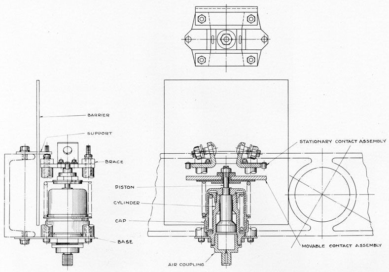
Switch.
The means provided for starting the motor consists of an air-actuated switch which receives high-pressure air from the air flasks upon tripping of the starting gear. When high-pressure air enters the switch chamber it forces the contacts to close and permits current from the battery to flow through the motor and propel the torpedo. The switch remains closed until the four-way valve (used only with the exercise head) is tripped by the motor rocker arm pin at which time the air pressure against the switch is permitted to escape through a relief valve connected to the four-way valve. This relief valve is so adjusted that when the four-way valve is tripped the air at the switch is slowly leaked off until the pressure drops to about 400 pounds per square inch., at which point the relief valve suddenly opens and permits the switch to open.
Switch.
The switch is mounted on the rear of the motor in series with the field circuit. An arc shield of asbestos-micarta is placed between the switch and the frame to prevent an arc, to frame, forming upon opening of the switch.
Switch Test.-Apply air pressure at 2,800 pounds per square inch to air connection on switch. Slowly vent off air until switch opens. Note opening pressure. Switch should open at 400 pounds per square inch.
90
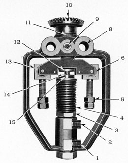
FIGURE 76-6.-Brush rigging details.
LEGEND
1-Connector ring.
2-Spring anchor bolt.
3-Brush connector.
4-Connector ring terminal
5-Brush.
6-Back of brushholder.
7-Front of brushholder.
8-Brush tension spring assembly.
9-Spring holder.
10-Spring.
11-Micarta ring.
12-Nut.
13-Bolt for rocker ring stop.
14-Nut to hold brushholder to micarta ring.
15-Bolt.
16-Nut and bolt to fasten brush connector to brushholder.
17-Speed control pin.
FIGURE 77-6.-Forward bearing details.
LEGEND
1-9/16 inch bolt holes.
2-Bearing.
3-Bolt holes for attaching governor.
4-Hole for grease cup.
5-Bracket for power piston.
6-Stop adjustment.
7-Stop.
8-Spring bracket.
9-Holes for fastening micarta ring.
91
FIGURE 78-6.-Rear end bearing.
LEGEND
1-Outside view of rear end bracket.
2-Grease cup.
3-Inside view of rear end bracket.
4-Bearing.
The governor used is a flyball type, one-way control, and is so designed that when the speed decreases the governor opens ports, permitting oil under pressure from the oil reservoir to force the piston of the power cylinder unit against the speed control pin on the rocker ring assembly thus shifting the position of the brushes so as to cause the motor to draw more current and thus prevent a drop in speed caused by a reduction in battery voltage. The governor speed is one-half the motor speed.
Disassembly.-
1. Remove piping to governor.
2. Remove governor from motor front end bracket.
3. Remove bevel gear.
4. Remove nut and washer at bottom of stem.
5. Remove cotter pin in stem.
6. Remove collar on stem.
7. Remove ball bearing from stem.
8. Remove spring seat.
9. Remove stem, spring, and valve from frame.
10. Remove spring from stem.
11. Remove valve.
12. Remove calibrating nut from valve.
13. Remove support assembly from frame; inspect and thoroughly clean all parts. Blowout ports and make sure they are clear.
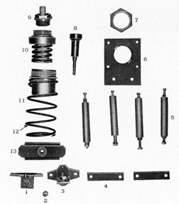
FIGURE 82-6.-Governor.
LEGEND
1-Connection to oil reservoir.
2-Connection to power piston.
3-Calibrating nut.
4-Spring.
5-Flyball arm.
6-Ball bearing.
8-Bolt hole for fastening to Motor End Bracket.
9-Grease fitting.
10-Bevel gear.
11-Scribe mark.
12-Slotted cap on shaft.
13 -Flyball arm elbow
14-Cotter pin.
15-Ball bearing.
1. Assemble support assembly in frame.
2. Assemble calibrating nut on valve.
3. Assemble valve in frame, using nut and washer.
4. Assemble spring stem.
5. Assemble spring seat.
6. Assemble ball bearing in seat.
7. Assemble collar on stem.
8. Assemble cotter pin in stem.
9. Revolve flyballs until slots in collar engage wheels.
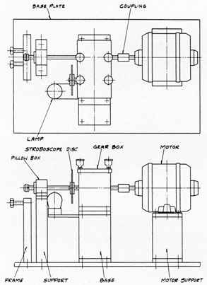
FIGURE 86-6.-Governor calibration outfit.
10. Revolve flyballs until ports are open to leads and observe benchmark. If backward, reverse.
11. Assemble bevel gear to shaft.
12. Calibrate as shown in calibration test.
13. Assemble on motor end bracket.
14. Connect piping from oil reservoir and power piston.
15. Apply no-load governor test. (See motor test.)
Governor calibration test.-Test for leaks at spindle at 400 pounds per square inch. One drop per minute leakage allowed. Revolve governor in same position as when on motor with a
97
direct current motor having a variable speed control, and with the oil reservoir and power piston connected, adjust flyballs until governor ports open at a speed of 1,650 to 1,660 r. p. m. The final adjustment is obtained by means of the calibrating nut. One turn of this nut is equivalent to about 100 r. p. m.
Four-Way Valve.
The four-way valve is a control which provides for the blowing of the exercise head at the end of the run and the opening of the switch in the motor circuit. It is mounted on the front motor bracket and is so designed that when the speed control pin reaches the end of its travel it trips a spring latch on the four-way valve causing the valve to suddenly change its internal
18-Link.
19-Assembled valve.
20-Lever (tripping).
21-Air inlet from starting gear.
22-Air to switch.
23-Air to exercise head.
24-Air to relief valve.
25-Valve body.
port connections as follows: In the cocked position the ports are so designed that air from the starting gear will pass to the motor starting switch thus starting and running the motor. The other port connects the relief valve with the line to the exercise head. At the end of the run when the speed control pin trips the four-way valve the ports are changed so that the high pressure air from the starting gear passes to the exercise head, while the motor switch lead is connected to the relief valve. The four-way valve tripping mechanism is cocked by rotating the link and shaft clockwise.
98
Disassembly of four-way valve.-
1. Remove cotter pins from pin and disassemble pin, lever, and spring.
2. Remove links. Do not remove rivets unless necessary.
3. Remove spring, retainer and shaft, and lever on frame.
4. Remove frame from valve body.
Assembly of four-way valve.-
1. Assemble frame to valve body using screws, lock washers.
2. Assemble spring with retainer and shaft and lever on frame.
3. Assemble links to valve and frame.
4. Assemble pin to frame using pins, lever and spring. Test for leaks by applying air and immersing in water.
Relief Valve.
The relief valve introduces a time delay during which the air from the motor switch is slowly leaked out for about 15 seconds until the pressure on the switch drops to 400 pounds per square inch, when the relief valve suddenly opens and permits the switch to open rapidly with a minimum of arcing.
At the time the motor is cut out, the exercise head has had time to expel most of its water ballast and the torpedo will have positive buoyancy.
Disassembly of relief valve.-
1. Remove cap and gasket from cylinder.
2. Remove piston.
3. Remove ball valve.
4. Remove nut.
5. Remove nut or guide holder.
6. Remove spring.
7. Remove guide and collar. Clean all parts and blow out air passage in cap.
Assembly of relief valve.-
1. Assemble ball valve in piston and insert in cylinder.
2. Assemble gasket and cap to cylinder.
3. Assemble guide and collar into spring and guide holder.
4. Assemble guide holder, spring, guide, collar in cylinder. 5. Assemble nut on guide holder.
Calibration of relief valve.-Adjust guide holder in cylinder until distance from outside top of guide holder to inside bottom of nut is 0.515 inch. Test with 400 pounds per square inch air pressure.
If valve fails to open in 20 to 30 seconds, adjust setting of guide holder and retighten nut.
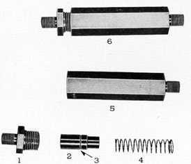
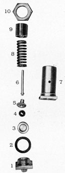
Power Cylinder.
The power cylinder provides means for shifting the brush rocker ring. It consists of a steel cylinder tapped at one end to receive the right-angle steel elbow for connecting the oil pressure pipe from the governor. The other end is threaded externally up to a shoulder to provide means for mounting.
A steel piston slides within the cylinder and extends out to the rocker ring and transmits the pressure from oil pipe to the rocker ring, against the counterpressure of the rocker ring tension spring.
99
The piston is provided with three oil grooves and is lapped into the cylinder. A small hole is drilled in the cylinder near the shoulder and is used to vent air out of the oil pressure system to avoid any air cushion between the oil and inner end of the piston.
Disassembly.-After removing from the end bracket, remove the elbow and withdraw the piston.
Inspection.- Clean all parts and check lapped surface. See that small vent hole is not plugged.
Assembly of power cylinder.-After cleaning, cover all surfaces with compounded steam cylinder oil, Symbol 5190 oil, and place piston in cylinder and screw on elbow. Mount on motor end bracket. (NOTE.-When filling with oil, force in oil until it begins to come out of vent hole. With pipe between oil reservoir filled with oil, press in on piston. If piston can be moved, air is trapped in system and should be worked out.)
The oil reservoir is interposed between the air pressure line and the governor. It consists of a cylinder, a piston, a piston spring, and a coupling. The cylinder is made of steel and reamed inside to size. The lower end is turned down to provide for a screwed pipe connection and the upper end is tapped for a reducing coupling. The piston is made of steel, ground to size, and has
518463-43-8
100
a reduced section at one end to retain the spring. An oil groove is provided on the full diameter section.
Disassembly.-Remove from the motor assembly by disconnecting the oil and air pipe. Remove the reducing coupling and tip over, allowing piston and spring to drop out.
Inspection.-Clean parts and inspect for scratches on piston and cylinder surface and dirt in oil groove.
Assembly.-Lubricate all parts with compounded steam cylinder oil. Put end of spring on piston and place cylinder over spring and piston. Turn cylinder over and screw in coupling and assemble on oil and air pipes.
Test.-Test with motor assembly.
Motor Disassembly.
Tool
1. Remove all piping to governor, oil reservoir, power piston four-way valve, and relief valve
5/8"
2. Remove flexible lead from field to rocker ring
7/16
3. Remove spring from end-bracket to rocker ring
Scdvr.
4. Remove front end-bracket with governor assembly and rocker ring assembly. Support armature with a block
9/16"
5. Remove speed control pin and spring anchor
13/16"
6. Remove three bolts holding rocker ring to end-bracket
3/8"
7. Remove six brush-holders from micarta ring
7/16
8. Remove six-brush-holders from connector ring
7/16"-5/8"
9. Remove 12 brushes and pigtail leads from holders
5/16"
10. Remove copper strap leads from field coils to switch
9/16"
11. Remove rear end-bracket and switch from frame
9/16"
12. Remove switch from bracket
3/8"
13. Remove armature.
14. Remove bolts from pole pieces to frame (tip frame on its side and remove all coils at once if it is desired not to disconnect the copper connecting straps)
1/2"
15. Remove pole pieces from field coils.
16. Remove grease cups from both end-brackets
1/2"
17. Remove bearings from end-brackets by pressing out from front to rear. Use
2-1/2" arbor
2 1/2"
18. Remove power cylinder from front bracket
1 1/2"
19. Remove oil reservoir from piping
5/8"
20. Remove governor from front end-bracket Scdvr.-3/4"
21. Remove four-way valve from front motor bracket
Scdvr.
22. Remove pinion gear from shaft.
Motor Inspection After Disassembly.
Armature and commutator.-Inspect condition of commutator bars; note any pitting or grooving. If pitted badly, take off a cut on the lathe and polish using fine sandpaper and a dense felt or canvas cloth. Never use emery paper.
Inspect mica insulation between commutator bars and, when necessary, undercut 1/16 ± 1/64 inch. Bevel edges of bars only enough to remove any burrs. Be sure no slivers of mica remain in slot. Clean with an air jet.
Inspect and remove any carbon dust that may be accumulated on the windings between commutator bars and core. Use air jet.
101
Inspect soldered connections where coils are connected to the commutator bars. Solder where necessary. Use a noncorrosive flux and pure tin solder.
Inspect for short circuits checking bar to bar. Use approximately 300 volts with a light in series.
Inspect windings for charring due to short circuits or overloads and where necessary repair damaged insulation by painting with an insulating varnish.
Inspect core, note looseness on shaft, loose laminations, etc.
Inspect armature balance. Rotate armature on knife edges. Check shaft.
Frame.-Inspect condition of field coils and insulation. Inspect for rigid mounting of poles and field coils on frame. Inspect for shorts. Apply 2,000 test volts between coil winding and frame 2 to 3 seconds.
Bearings and end brackets.-Inspect and replace badly worn bearings.
Inspect and fill grease cups and see that line is clear.
Do not over lubricate. Use Beacon No. 285 or equivalent.
Rocker ring assembly.-Inspect and clean off all carbon dust and check all electrical clearances.
Inspect and replace all badly worn brushes. Brushes should be at least 70 percent seated and if not, grind them in with fine sand paper and then blow out with air.
Inspect brush springs. Adjustment made after assembly.
Inspect connectors to connector rings.
Inspect flexible leads for wear and tape where necessary.
Motor Assembly and Tests.
Rear bracket subassembly.-
Tool
1. Assemble bearing into rear bracket. Use Arbor press
2 1/2"
2. Assemble grease cup and fill with grease
1/2"
3. Assemble air switch and arc shield to rear end bracket
3/8"
Front bracket subassembly.-
1. Assemble into front bracket. Use Arbor press
2 1/2"
2. Assemble grease cup and fill with grease
1/2"
3. Assemble rocker ring, brush holders, and connector ring
3/8"
Subassembly: Apply thin coat of graphite grease to bracket.
(a) Assemble brushholders on fixture and rocker ring
7/16"
(b) Assemble connector rings onto brushholders
7/16-3/8"
(c) Assemble spacers into connector rings.
(d) Assemble brushes to brushholders
5/16"
4. Assemble speed control pin and accessories
1 3/16"
5. Assemble rocker ring spring.
6. Check clearance between rocker ring clip and brushholder. This should be 1/8 inch.
Frame assembly.-
1. Assemble main pole and field assembly to frame
1/2"
NOTE: Be sure to insert spring clips between field coils and frame.
2. Test field coils to frame at 2,000 volts for 2 to 3 seconds for ground.
3. Assemble and braze' cross connectors-tape and varnish
9/16"
4. Assemble rear bracket subassembly to frame and braze air switch connectors-tape and varnish
19/16"
5. Assemble thrust rings to armature shaft and assemble into frame and rear bracket.
102
Tool
6. Assemble front bracket subassembly to frame
9/16"
7. Check armature end play-should be 0.024 to 0.076 inch. Keep approximately 0.040 inch. Use dial indicator.
Check air gap between pole faces and armature. Should be 3/16 inch.
9. Braze connector ring lead to field
7/16"
10. Tape and varnish connector ring lead to field.
11. Assemble lead clamp and bracket.
12. Check brush tension on commutator. Should be 2 3/4 to 3 pounds.
13. Check brush holder springs against any possible grounds to frame and spring.
14. Assemble bolts for battery connections on motor leads.
15. Assemble power cylinder
1 1/2"
16. Assemble governor, bevel gear, and check end play
3/4"
17. Assemble oil reservoir and fill with compounded steam cylinder oil
5/8"
18. Check for air pockets in the governor oil system. Oil should come out of power cylinder vent.
19. Test insulation to frame at 1,500 volts for one minute.
20. Test between positive and negative rings at 2,500 volts.
21. Assemble four-way valve to motor front end bracket.
Motor inspection after assembly for following.-
1. Bearings greased. Do not over lubricate. Beacon No. 285 recommended.
2. Armature rotates freely.
3. Armature end plate. Check with dial indicator. Should be 0.024 to 0.076 inch average 0.040 inch.
4. Armature coil clearance; to rear bracket.
5. Rocker ring free to move.
6. Commutator finish. Clean with a canvas cloth free from lint, or use 00 grade sandpaper.
7. Connector ring clearance; to front bracket; to field coil connections.
8. Power piston filled with compounded steam cylinder oil. Check for air in line.
9. Oil reservoir filled with compounded steam cylinder oil. Check for air in line.
10. Spline joint cleaned.
11. Governor gears adjusted.
12. Brush pressure adjusted to 2 3/4 to 3 pounds. Brushes should be at least 70 percent seated and free to move in holders.
13. Starting switch connections tight.
14. Motor terminals taped properly.
15. Motor hardware tight.
16. Governor speed (see no-load governor test).
17. Stops on rocker ring. Set initial stop setting at 1/4 inch (head of bolt). This is approximately 1,600 r. p. m. or 60 r. p. m. below rated speed. Upon starting at normal voltage, governor will push brushes to proper position.
18. Brush springs clipped.
19. Brush shunt screws tight.
20. Pole support bolts tight.
103
Motor test.-
(a) No-load test:
1. Adjust voltage to approx. 20 volts and run at 900 r. p. m. clockwise.
2. Check motor bearings for heating.
3. Check governor gears for noise, etc.
4. Check armature balance. Note excessive vibration.
5. Check commutator. Note excessive sparking.
6. Check seating of brushes. Should be at least 70 percent.
FIGURE 91-6.-Checking armature end plug.
LEGEND
1-Dial indicator.
2-Adaptor for fitting inside of shaft.
3-Adaptor for fitting inside of shaft.
4-Steel plate bolted to end bracket.
5-Contact point.
FIGURE 92-6.-Dial indicator for checking armature end play.
LEGEND
1-Contact point.
2-Bezel clamp.
3-Bezel.
4-Adjusting screw.
5-Adjusting screw.
6-Dial holding rod.
104
7 Stop motor and check torque, in pounds measured 12 inches from shaft center, to rotate armature.
8. Stop motor and check torque in pounds, measured 7 inches from shaft center, to rotate rocker arm.
Adjustments and Tests.
Motor and motor control with exercise head.-
(a) Inspect motor for following.
1. Bearings greased. Do not over lubricate. Beacon #285 recommended.
2. Armature rotates freely.
3. Armature coil clearance; to rear bracket.
4. Rocker ring free to move.
5. Commutator finished. Clean with a heavy felt or canvas cloth free from lint, or use 00 grade sandpaper.
6. Connector ring clearance: to front bracket, to field coil connections.
7. Power piston filled with compounded steam cylinder oil.
8. Oil reservoir filled with compounded steam cylinder oil.
9. Spline joint cleaned.
10. Governor gears adjusted.
11. Brush pressure adjusted to 2 3/4 to 3 pounds. Brushes should be at least 70 percent seated and free to move in holders.
12. Starting switch connections tight.
13. Motor terminals tapped properly.
14. Motor hardware tight.
(b) No load governor test:
1. Power cylinder should start in 1 second at 1,500 r. p. m.
2. Adjust voltage until speed is 1,550 r. p. m., power cylinder should operate until speed is increased to 1,660 r. p. m. Speed is increased by slowly increasing impressed voltage.
(c) Resistance measurements at 75° C.:1
1. Take measurement of armature resistance (limit: 0.0131-0.0119).
2. Take measurement of field resistance (limit: 0.0113-0.01025).
(d) Load test and heat run: use a separately excited compound wound generator as the load. Take readings every 1/2 minute for the following for 3 minutes.
(1) Motor
volts
(2) Motor
amps
(3) Load generator
volts
(4) Load generator
amps
(5) Speed
r. p. m.
1 Divide by 1.20 for values at 25° C.
105
Measure motor input
watts
Measure loading generator output
watts
Measure loading generator no load losses
watts
Measure loading generator load losses
watts
Measure loading generator total losses
watts
15. Stops on rocker ring. Set initial stop setting at 1/4 inch (head of 1/4 bolt) this is approximately 1,600 r. p. m. or 60 r. p. m., under rated speed. Upon starting at normal voltage, governor will push brushes to proper position.
16. Brush springs clipped.
17. Brush shunt screws.
18. Pole support bolts tight.
19. Grease governor alemite fitting and gears.
20. See that four-way valve is cocked. (Revolve link clockwise.)
2. Apply no-load motor test. (See motor test.)
3. Apply no-load governor test. (See governor no-load test.)
4. Test switch, four-way valve and relief valve as follows:
(a) Apply approximately 1,000 pounds per square inch air pressure to switch.
(b) Run motor at reduced speed (20 volts, approximately 900 r. p. m.).
(c) Observe that power piston operates smoothly to end of its travel and trips four-way valve. Note that spring action is positive.
(d) Observe action of relief valve. Should open when pressure reaches 400 pounds per square inch.
(e) Observe action of motor switch. Should open rapidly after relief valve operates.
5. Cock four-way valve after above test.
6. Reset rocker arm to initial position against stop.
With war head.-
1. Remove four-way valve and relief valve.
2. Install nipple in female connections in piping, thus connecting starting gear directly to motor switch.
Lubrication.-
1. Check grease cups on motor front and rear end brackets and see that bearings are lubricated.
2. Check alemite grease fitting in governor and lubricate if necessary.
3. Check governor bevel gears for grease. Lubricate if necessary.
4. Check and fill oil reservoir with compounded steam cylinder oil.
Drying cut motor.-If motor becomes damp from exposure to moist air, it should be dried out. If motor becomes wet from sea water, it should be removed from the afterbody, all parts disassembled, and thoroughly washed with fresh water, to remove any deposit of salt. Particular attention should be given to the commutator, thoroughly cleaning out the slots between the segments with a scraper, after washing and drying. Remove all lubrication and replace when assembling.
Inspect all parts of motor and control as previously described and reassemble and test. Any corroded parts should be replaced, and if motor has been submerged in salt water any great length of time replace motor brushes with new ones.
Resistance values after drying out (limits at 75° C.):1
Series coils, 0.0113 to 0.01025.
Armature, 0.0131 to 0.0119.
1 Divide by 1.20 for values at 25° C.
106
This page blank.
107
DEPTH CONTROL MECHANISM
Chapter 7. DEPTH CONTROL MECHANISM
108
GENERAL DESCRIPTION OF DEPTH CONTROL MECHANISM
The depth control mechanism has for its sole function maintenance of the torpedo at the desired depth below the surface during a run. This function is accomplished by two horizontal rudders acting as one. The rudders are located on each side of the torpedo just forward of the propellers and in line with the horizontal tail vanes.
The major units of which the depth control mechanism is composed are as follows:
The gyro mechanism and the immersion mechanism are both contained on the same base, which is a large bronze casting fastened by screw bolts to a frame solid electric arc welded from outside to the bottom of the afterbody shell. A gasket is fitted between the base and frame to make this joint watertight.
The inner surface of the mechanism base is tinned as necessary to enable it to withstand an external hydraulic pressure of 135 pounds per square inch without leakage. The immersion mechanism is installed on the forward end of the base and the gyro mechanism is on the after end. The base is provided with necessary access openings for the various units of the gyro and immersion mechanism.
DETAILED DESCRIPTION OF DEPTH CONTROL MECHANISM
The depth control mechanism used in the Mark 18 torpedo is identically the same as that used in the Mark 14 type torpedo without the addition of the conversion described in Conversion List No. 39. It is adequately described in Ordnance Pamphlet 635.
CALIBRATION OF DEPTH SPRING
The depth spring of the Mark 18 torpedo should be calibrated using a 14-pound weight for 10-foot setting.
109
THE GYRO MECHANISM
Chapter 8. THE GYRO MECHANISM
110
GENERAL DESCRIPTION
1. The gyro mechanism is the housing in which the gyroscope is contained and to which he impulse mechanism, together with the mechanism necessary for relaying gyrostatic control if the torpedo, is assembled.
2. The gyro mechanism, together with the immersion and depth control mechanism, is assembled on one large base, which may be removed or replaced in the afterbodies of torpedoes without affecting the adjustments of the individual mechanisms assembled thereon. The depth and vertical steering engines must be removed, however.
3. The gyro pot is a large cylinder, the lower end of which is seated in a circular recess in the After end of the base, and opening from the outside for the insertion of the gyro. The upper end if this cylinder is closed by a bronze top plate, thus forming a housing for the gyro when installed n a torpedo.
4. The gyro pot is a fixed part of the base, being rigidly secured to same by screws and solder and suitably machined with bosses and bearing surfaces on its outer cylindrical wall for the installation of the gyro impulse mechanism on the after side, and the depth and steering engines in the port and starboard sides. The top plate on which the pallet mechanism is assembled is field against a lapped surface on the upper end of the pot with retainer plates and is capable of movements in azimuth each way from the central position in relation to the fore and aft position A the pot, thus affording a means for angle fire adjustments to the right or left.
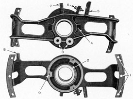
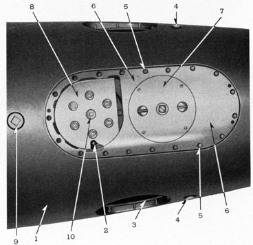
FIGURE 93-8.-Gyro and immersion mechanism base plate.
LEGEND
5. The gyro mechanism base is a bronze casting of suitable dimensions for mounting the depth and gyro mechanisms: The outer side of the base is machined to conform with the contours of the afterbody, the inner side being machined with a seat to fit against a gasket in the gyro door flange on the afterbody shell to which it is secured with screws. A circular opening in the forward end is machined with a flange for mounting the depth mechanism, the gyro pot being mounted in a circular recess in the after end. The base is bored out to fit the outside diameter of the pot, so that the pot may be inserted and sweated in place. The inside of the after end of the base is suitably machined for attaching the bottom angle setting device. Four holes are drilled and tapped on the exterior of the base between holes for the holding screws for the insertion of lifting screw tools when removing or assembling in afterbody.
DETAILED DESCRIPTION
The gyro mechanism used in the Mark 18 torpedo is identically the same as that used in the Mark 14 type torpedo, except that no air is supplied for continuous spin. Description, adjustment, care and operation of this mechanism is given in Ordnance Pamphlet No. 635.
112
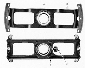
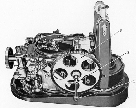
FIGURE 95-8.-Gyro and immersion mechanism.
LEGEND
1-Depth engine.
2-Strainer.
3-Control valve stop.
4-Connecting rod.
5-Pendulum lever.
1. The gyroscope used in the Mark 18 torpedo is designated Mark 12 Mod. 3.
2. Description, adjustment, care and operation of this mechanism is contained in Ordnance Pamphlet 635, the gyro being identical, including channels for continuous spin air, although air for this purpose is not supplied in the Mark 18 torpedo, the gyro decreasing speed during the run.