The afterbody is the container for propelling the mechanism and controlling units and is similar to the Mark 14 torpedo afterbody. It is made of 3/32-inch sheet steel in two easy curve halves welded together horizontally and is cylindrical on its forward end and conical on the after end.
There are 12 steel strengthening rings electric arc, tack-welded to the inside of the afterbody to reinforce it. In manufacture, the rings are welded in place by working from aft-forward and the motor cage is welded to forward end of the afterbody from the outside. The motor cage has 6 lugs machined on its inside circumference, drilled and tapped for 3/8-inch bolt. These lugs support the motor, which is held by six 3/8-inch steel bolts and 6 lock washers. There are also 26 holes around its outer edge for the 26 joint screws used in clamping the afterbody to the battery compartment.
A groove is machined out on the forward afterbody joint ring, and a rubber gasket is put in the opening. On the after end of the battery compartment the joint ring is machined in the shape of a knife edge, and when the afterbody is assembled to the battery compartment, the knife edge comes against the rubber gasket, and when drawn into place by the 26 joint screws, forms a watertight joint.
The after-bearing plate joint ring is attached by welding from the outside. This ring is drilled and tapped near its outer edge for 12 5/16-inch, 24-thread screw for securing the tail cone. The joint ring is also flanged and has 12 5/16-inch, 24-thread holes drilled around the inner edge, to hold the afterbody bearing plate in place.
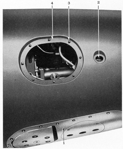
There are several openings in the afterbody for various mechanisms. When these openings are made, some of the strengthening rings are cut, but when the flanges are welded in place, the rings that have been cut are welded to the flanges. All flanges are made of steel and are solid electric arc welded from the outside to the afterbody shell. These openings are located as follows:
Starting Gear Flange.
(1) The starting gear flange is positioned the same as in the Mark 14 torpedo, about 16° to the right of the centerline and 88.813 inches± .080 inch from forward end of guide stud to forward end of starting lever. The top of starting lever is about .125 inch below the surface of the battery compartment, extended.
Depth Index Socket Flange.
(2) The depth index socket flange is in the centerline of the afterbody-83.218 inches from forward side of the guide stud to centerline of depth index dial. The depth setting device is the same as used in the Mark 14 torpedo. See chapter 7.
Stop and Charging Valve Flange.
(3) The stop and charging valve flange is on top of the afterbody, left of the centerline-45.313 inches from the after end of the torpedo. The first 75 stop and charging valves bodies are made in one piece, and held in place by screws on vellumoid gasket. The new type stop charge valves will be made in two sections and welded to the shell of the afterbody and connected by copper tubing.
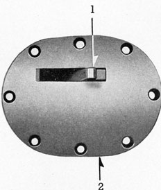
(4) Two handhole cover plate flanges are welded to the shell of the afterbody just below the right and left horizontal centerlines. They are in the same position as in the Mark 14 torpedo, the only difference being that the flanges are made of steel, solid welded from the outside, and the studs that the handhole plates are secured with are welded to the flanges. The hand-hole plate is made of aluminum and is seated on a vellumoid gasket and is secured with eight 1/4-inch 20-thread hexagonal nuts.
Gyro Side Setting Socket Flanges.
(5) Two gyro side setting socket flanges are in the same position as in the Mark 14 torpedo, just aft of the hand holeplates. The gyro setting socket is sealed with a leather washer.
Drain Plug Flange.
(6) The drain plug flange is welded in place on the bottom of the afterbody, just aft of the joint line. The drain plug is made of brass, and it seats on a copper washer.
(7) The gyro housing flange is welded to the bottom on centerline of the afterbody. It has 19 holes, 9/32 thread tapped. The gyro housing seats on a vellumoid gasket, and is secured with 19 studs.
Heater Terminal and Cover Opening.
(8) The heater terminal and cover opening is aft of the gyro housing. The two conductors are carried in copper tubing, leading aft along the bottom of the afterbody shell to the tail vane, one part of tubing on either side of tail vane. The after part of the vane is split to allow tubing to run down into rudder bearing, where connections are made. The tubing is held by one clip under the bottom tail vane. The conductor going through the afterbody is secured in the bottom to strengthening rings, clear of all gears.
Near the afterend of the afterbody shell, 8 holes are drilled-2 on each right and left centerlines, and 2 on upper and lower centerlines, a slotted lug is put in each of these openings and welded from inside. The lugs are drilled and tapped for 1/4' 20-thread machine screw. In assembling the tail cone the vanes are secured to these lugs.
After all strengthening rings, flanges, and joint rings are secured in place and finished, the afterbody is dipped in a parkerizing solution. This leaves a coating of phosphate. The afterbody is then dipped in cromic acid. Then a coating of alkyd varnish is applied, using the easy flow method; allowed to drain and bake for 6 hours. This gives a protective coating of approximately .006 inch thick.
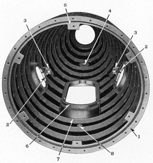
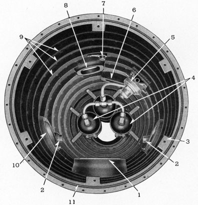
Nested near the afterend of afterbody, inside on top, in a pyramid formation, around the main shaft, are three air flasks, held by two supports each, the supports being secured to the strengthening rings with bolts, nuts, and lock washers. These flasks supply all the air that is
51
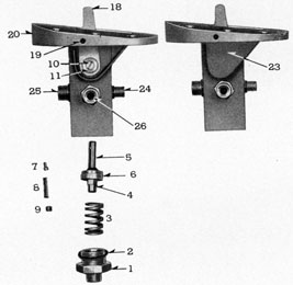
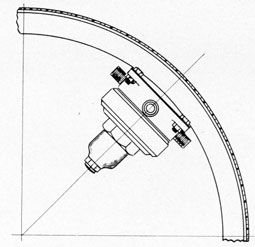
FIGURE 37-5-View through afterbody handhole
LEGEND
needed in this torpedo. Exhaust air in the afterbody is vented into the battery compartment through the check valve in the after bulkhead.
Inside the afterbody a flat steel plate is tack welded to No. 5 and 6 strengthening rings, and on this the reducing valve is secured with four bolts.
TESTS
In manufacture, the afterbody must pass the following tests: After all welding is finished, blind flanges are put on forward and aft, and where necessary to close all openings. Drain plug and handhole covers are installed. Internal air pressure of 10 pounds per square inch is applied,
518463-43-5
52
and all welds and gasket joints tested with soapy water for tightness. Following this test, after-body is subjected to an external hydrostatic pressure of 150 pounds per square inch for 5 seconds. After this, the afterbody is tested with an external hydrostatic pressure of 135 pounds per square inch for 30 minutes, during which time there should be no leak.
THE STARTING GEAR
The function of the starting gear is to automatically start the mechanism of a torpedo, upon launching from a torpedo tube, and to permit manual operation of this mechanism for starting when testing the torpedo.
Description.
The starting gear is mounted in an irregular-shaped fabricated, steel body (starting gear body), secured to a flange located at the top and to the right of the centerline of the afterbody. This flange is welded to the afterbody shell, the joint between the starting gear body and the flange being made watertight by a sheet packing gasket. The outer face of the starting gear body is machined to conform with the contour of the afterbody shell. Three pipe fittings are screwed and silver-soldered into threaded holes in the starting gear body to provide connections for the air pipes to the spinning mechanism, reducing valve, and motor switch.
The tripping cam is installed in the starting gear body, with a nylon washer, on the tripping cam stem. The washer is interposed between machined grooves on the starting gear body and the tripping cam. The tripping cam spring is placed behind the cam, and the cam plug and washer is screwed into the threaded hole in the body. The spring forces the tripping cam firmly against the nylon washer, thus preventing air leakage around the tripping cam stem. Asbestos string packing is wound around the tripping cam stem, a packing gland nut is screwed into threaded hole in the body, compressing the packing around the cam stem, preventing leakage of water into the body.
The starting lever is placed in the elongated slot, and the square hole machined in the lower end receives the square end of the tripping cam stem. The starting lever is secured by a washer and a machine screw threaded into a hole in the end of the stem. The body cover is welded to the body cover bracket to prevent leakage of water into the afterbody.
The starting valve proper is a nylon washer, pressed into a disc, which is secured to the valve lift by the valve lift nut at the bottom of the disc. The starting valve closes against a seat machined in the starting gear body. The starting valve spring is located between the starting valve and body plug. The compression of this spring and flask air pressure tends to seat the starting valve. The upper (free) end of the starting lever, projecting above the outside of the body sufficiently to engage the tripping latch of the launching tube, is thrown to the rear when the torpedo leaves the tube; the tripping cam is rotated; the upper end of the valve lift in contact with the cam is forced down, unseating the starting valve. A hole drilled in the side of the starting gear body, contains a lock pin, spring, and plug. When the starting lever is in the fired position, the lock pin spring forces the lock pin out across the slot, positively locking the starting lever in the fired position.
53
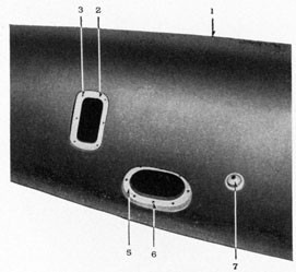
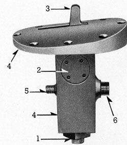
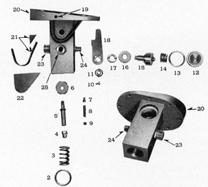
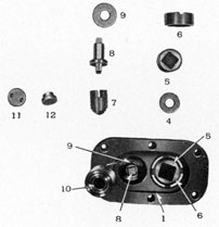
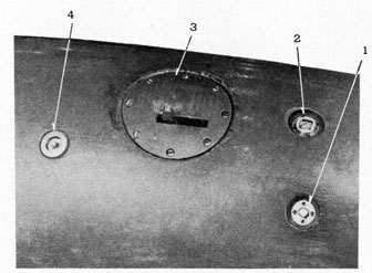
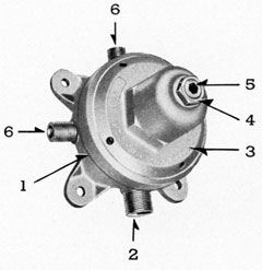
FIGURE 39-5.-Starting gear top view.
1-Body plug.
2-Cam plug.
3-Starting lever.
4-Starting gear body
5-Pipe fitting 1/2-20
6-Pipe fitting 1/4-24.
6. Remove lock pin, plug, spring, and lock pin. The tripping cam and starting lever is not removed on normal overhaul. The cover plate must be chipped off the starting gear body to gain access to the starting lever keep screw.
7. Wash starting gear body and parts in gasoline, inspect for worn parts, corrosion, dress threads in holes and parts, renew nylon seat of starting valve if necessary.
8. Lubricate all parts, and the interior of the starting gear body with light mineral oil. 9. Replace tripping camp spring, plug, and washer.
11. With starting lever forward, in the cocked position, with depth micrometer on lower face of starting gear body, across the body plug hole, measure distance to valve lift nut. Move starting lever, to extreme after position, the fired position, measure distance from face of the body to valve lift. The second reading should be .0625 or his inches less than the first reading.
12. Replace starting valve spring, body plug, and washer.
13. Blank off two outlet pipe fittings, on the starting gear body.
14. Cock starting gear.
15. Connect high-pressure air pipe to air inlet fitting on body plug. Air pressure 2,800 pounds.
16. Open valve in the line admitting air to the body.
17. Inspect for leaks, with a cup of water over the open outlet pipe fitting on the body. 18. Nylon seat must be renewed in case of a leak.
To Assemble Starting Gear in Afterbody.
1. Clean face of starting gear flange, pass tap through holes in the flange to clear the threads.
2. Place new sheet packing gasket on the flange.
3. Install starting gear with eight holding screws.
4. Connect main air pipe to body plug fitting.
5. Connect air pipes from the spinning mechanism, reducing valve, and the motor switch, to the fittings on the starting gear body.
THE CHARGING AND STOP VALVE
The charging valve provides a means for charging air into the air flasks. The stop valve provides means for isolating the air in the flasks at will, after charging, until ready for use, thereby making it possible to disassemble and overhaul all parts of the torpedo while the air flasks are charged.
The charging and stop valve body is a steel forging, machined and threaded to receive the charging and stop valve assemblies. This body is secured by machine screws, to a flange, welded to the top of the afterbody shell, near the forward end to the left of the centerline.
The charging valve body receives the charging valve bushing, which is held in place by a small keep screw, and in turn receives the charging valve plug. This bushing can be replaced in case the threads are damaged. The charging valve and plug are riveted together in such a manner that the valve may turn on the plug. A fiber washer is interposed between the charging valve and the seat in the body to prevent air leakage to the atmosphere when the stop valve is open.
When the air flasks are charged, the charging valve, and washer are removed from the body. The wing nut of the charging pipe is then screwed into the hole vacated by the charging valve and plug. After charging pipe is removed, the washer and charging valve are again put in place.
The stop and charging valve when made in two pieces uses the same internal parts as the one-piece combination stop and charging valve but the bodies are separate and welded to the shell instead of clamped to a flange welded to the shell.
The assembly and disassembly of the separate valves is the same as that used with the combination body except that the bodies cannot be removed from the torpedo shell.
56
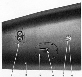
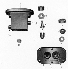
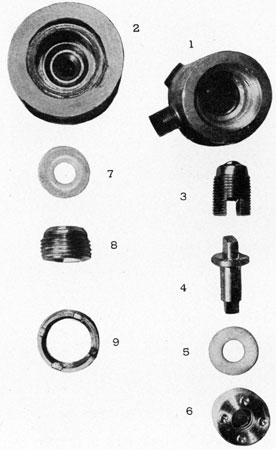
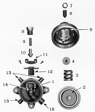
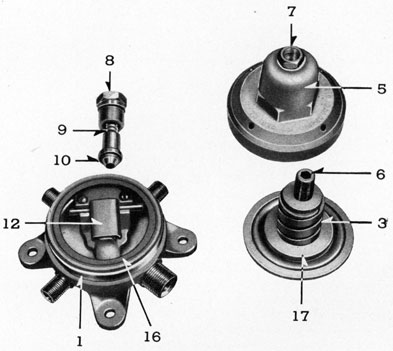
FIGURE 44-5.-Charging and stop valve.
LEGEND
1-Charging and stop valve body.
2-Recess for stop valve.
3-Recess for charging valve.
4-Charging valve washer.
5-Charging valve and plug.
6-Charging valve bushing.
7-Stop valve carrier and valve.
3-Starting gear with round body flange.
4-Depth setting index and spindle.
The Stop Valve.
The stop valve assembly consists of the following parts: (1) The stop valve and carrier, (2) the operating spindle, (3) nylon washer, (4) stop valve plug. The stop valve proper is a stainless steel ball which seats on an alloy copper seat, pressed into the body. Supporting the alloy seat in the body is a steel plug, screwed and silver soldered in place. This valve is of the compression type, and makes its own seat in the copper alloy insert in the body. The stop valve body is threaded to receive the stop valve carrier. The top of the carrier has a machined recess, to receive the shank of the operating spindle. The stop valve proper (steel ball), is fitted to the bottom of the carrier in such a manner that it is free to rotate, but travels with the carrier. The stop valve plug, screws into the threaded body, and a hole drilled in the center of the body forms a guide for the operating spindle. Machined grooves on the lower face of the plug are in contact with the nylon washer that is interposed between a machined shoulder on the spindle and the stop valve plug when the valve is open wide, forming an air-tight seat, preventing leakage of air around the spindle or plug. The operating spindle or nylon washer may be replaced, with the air flasks charged, by closing the stop valve tight on its seat, and removing the stop valve plug. The spindle and washer can then be lifted out and necessary parts renewed.
Overhaul and Tests For Charging and Stop Valve.
1. Disconnect main air pipe between the charging and stop valve body, and upper center air flask.
2. Disconnect main air pipe between valve body and the starting gear.
3. Remove holding screws, remove the valve body from the afterbody flange.
4. Place charging and stop valve body in a vise.
5. Remove charging valve plug and washer.
6. Remove stop valve plug.
7. Remove operating spindle and nylon washer.
8. Remove stop valve carrier.
60
9. Inspect, dress threads, in the body and on the pipe fittings.
10. Clean body and blow dry with low pressure air.
11. Clean and inspect parts of the valve, for corrosion and erosion, lubricate with light mineral oil.
12. Assemble parts in the body, close the stop valve.
13. Connect high pressure air pipe to inlet pipe fitting, test stop valve with 2,800 pounds pressure on the line, by holding cup of water over outlet pipe fitting on the body.
14. Place blank on outlet pipe fitting.
15. Open stop valve.
16. Test with oil around the operating spindle, stop valve plug, and charging valve plug.
ANGLE FIRE SETTING DEVICE AND GYRO SIDE SETTING SOCKET
Description.
1. The angle fire device is the means provided for changing the torpedo's course through the water after launching.
2. This is accomplished by rotating the gyro top plate in either direction until the desired angle between the pallet pawls and the cam on the gyro is obtained. An index graduated to 160° in increments of 5° each way is scribed on the retainer plates for the top plate, the reference pointer for this index being secured to the pot by two screws.
3. The gyro with the cam pawls is held central, in the fore and aft line, with the torpedo before the top plate is turned and the pallet mechanism is moved to the desired angle by turning the top plate.
4. Thus it will be seen that the initial spin is imparted to the gyro when in the fore and aft plane of the torpedo and after taking its angle the gyro is running at the set angle from this plane. The Mark 18 torpedo is equipped with side setting device only.
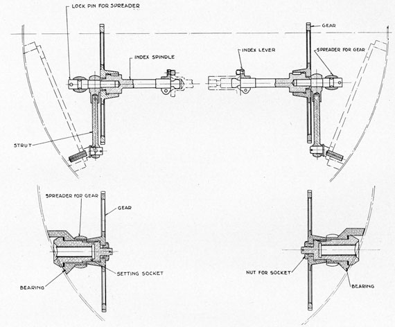
5. The top plate is rotated by a worm carried in a bracket attached to the gyro pot and meshing with the teeth cut around the periphery of the top plate, the flanged ends of the worm shaft and the sockets attached to this shaft being suitably machined for connecting with the index levers.
6. Gyro index bearing brackets are welded on each side of the afterbody, the interiors of these brackets -being suitably machined for bearings for the gyro index sockets. Shoulders machined in these bearings form the seats against which the side setting sockets bear, leather washers being interposed between flanges on the side setting sockets and these shoulders to form a watertight seat. The outside diameters of the inner ends of the bearing brackets are suitably machined to fit the holes in the after ends of the spreaders.
7. The outer ends of the side setting sockets are machined with square holes for the insertion of the operating spindle or setting tool, and are flanged to form seats for washers. The outer faces of the flanges are graduated in five equal spaces and so arranged through the gearing that one complete turn of the setting spindle equals 5°, each space marked off being equal to 1°. Coincidence marks and "right" and "left" indicator arrows are stamped on the afterbody shell. The after gyro index gears are keyed to and secured in place on the inner ends of the sockets by nuts and cotter pins.
8. The spreaders in combination with the struts support the forward gyro index gears and the outer ends of the index spindle by the insertion of lock pins which pass through the spreaders and struts with the projecting inner ends of these pins forming the pivots about which the index spindles turn.
61
9. The forward gyro index gears are attached to the outer end of the index spindles, the inner ends of these spindles being machined with a ball end for insertion in the sockets of the index worm spindle. Index levers are secured around the inner ends of the index spindles by clamp screws, the outer ends of these levers being fitted with pins for entry into the slots cut on the periphery of the index worm sockets to transmit the turning torque in either direction.
10. By turning the setting socket from either side, motion will be imparted from the after to the forward gyro index gear and through the index spindle and lever to the index worm spindle
FIGURE 49-5.-Gyro Index-Side setting sockets.
and the worm, which meshes with worm wheel teeth cut around the outer rim of the top plate and will turn the top plate in the direction and through the angle desired.
11. To illustrate, the operation of the angle fire gear; assuming that a torpedo is in all respects ready for a run, the gyro being locked with the angle fire setting checked at zero, it is desired to launch the torpedo on a 60° left turn. Engage the angle fire setting device on the tube setting socket on torpedo, turn in direction indicated left by the arrow until indicator on tube registers 60°, thus rotating the top plate correspondingly for left turn.
62
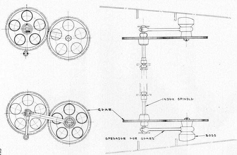
FIGURE 50-5.-Gyro index gears.
63
12. As the top plate turns, carrying the pallet and its mechanism with it, the right cam pawl rides over the cam, pushing the pallet to the left. In this position when the torpedo is launched and running, the left pallet pawl will be pushed back, transmitting this movement through the pallet linkage to the steering engine valve, moving the valve forward. With the admission of air pressure on the forward side of the piston, the piston with steering rod connections and free end of rudder yoke will be pushed aft with a consequent angular movement of the gyro steering rudders to the left.
13. Under the influence of this left rudder, the torpedo turns to the left as soon as it strikes the water. The gyro maintains its original plane of rotation and the torpedo turns around it, bringing the cam pawls back along the concentric edges on the cam plate until, after a turn of 60°, the right cam pawl passes the cam and the left pawl, riding up on it shifts the angle of the pallet, reverses the rudder throw, and thus straightens the torpedo on its set course.
14. The function of the angle fire device having been accomplished, for the remainder of the run the operation of the gyro is as for a straight run, the axis of the gyro wheel being at an angle of 60° to the axis of the torpedo instead of parallel to it.
15. This design of mechanism thus keeps the gyro wheel axis nearly in line with the torpedo axis during the initial roll of the torpedo upon launching and makes tumbling less likely. It is an assurance that the torpedo will successfully angle under extremely severe launching conditions.
GYRO SIDE SETTING MECHANISM
Disassembly From Afterbody.
Remove following parts :
1. Remove eight nuts for each and two handhole plates with gaskets.
2. Remove cotter pin, retained pin and lock pin for spreader.
3. Swing gyro index spreader and strut clear and remove the forward gyro index gears with index spindles and levers assembled.
4. Remove two connecting pins for forks and steering rods.
5. Remove air pipe to depth engine.
6. Remove air pipe to gyro engine.
7. Disconnect valve connections and remove depth and gyro engines.
8. Remove air pipe to gyro spin.
9. Remove gyro clamp plate.
10. Lock impulse mechanism.
11. Replace gyro clamp plate.
12. Remove 19 holding screws for gyro mechanism.
13. Insert transportation pin.
14. Insert lifting screws.
15. Lift out mechanism.
Remove gyro index setting device from afterbody.
1. See steps (2) and (3) in the preceding steps for removal of spreaders and index gear.
2. Remove cotter pins and index gear struts.
3. Remove cotter pins and nuts for gyro index setting sockets and gears.
4. Remove after index gears and gyro index spreaders.
5. Remove gyro index sockets and washers.
Remove starting gear from afterbody.
1. Disconnect main air pipe from stop and charge valve body.
2. Disconnect air pipes from reducing valve, gyro spin, and motor switch.
64
3. Remove holding screws for starting gear.
4. Lift starting gear from afterbody.
Assembly of Side Setting Mechanism in Afterbody.
Assemble gyro index setting gears in afterbody.
1. Clean gyro index bearing for socket with particular reference to seat for washer for gyro index setting socket.
2. Clean, inspect threads for burrs, replace washers and index setting sockets in bearings.
3. Clean and inspect gyro index spreaders for alinement and replace over gyro index bearing setting sockets.
NOTE.-Spreaders are marked right and left.
4. Clean and inspect gyro index gears (place on surface plate and check alinement), replace gear on index setting sockets with keyways in line, secure with holding nuts and cotter pins.
5. Clean, inspect, and replace gyro index strut, and secure with cotter pin.
6. Clean and replace index lever on index spindle, clamp in place with screw. 7. Insert spindles in index gears with keyway in line.
NOTE.-Forward index gears with levers and spindle should not be installed until after installation of gyro mechanism.
DISASSEMBLY OF DEPTH INDEX ASSEMBLY FROM AFTERBODY
Remove depth index assembly from afterbody.
1. Remove cotter pin and nut for index spindle.
2. Push shaft out clear of center hub, and remove center gear and side gear spindle with socket.
3. Remove index shaft by pushing out through the packing.
4. Remove index dial and pinion.
NOTE.-It should never be necessary to remove the fixed annular gear.
5. Remove gland and packing.
ASSEMBLY OF DEPTH INDEX ASSEMBLY IN AFTERBODY
Assemble depth index assembly in afterbody.
1. Clean, inspect, and oil depth index spindle, dial, and pinion.
2. Insert spindle through dial and slip pinion over cam on spindle.
3. Insert spindle, dial, and pinion assembly in depth index casing, turning in mesh with annular gear.
4. Replace required number of felt packing rings soaked in oil and set up on packing gland. 5. Clean, inspect, oil, and replace side gear spindle and socket, and center gear with washer, secure with nut and cotter pin.
THE REDUCING VALVE
Purpose.
The reducing valve receives the flask pressure air at a falling value, and delivers it to the depth steering engine, gyro steering engine, and motor control unit, at a reduced constant pressure of 400 pounds.
Location.
The reducing valve is secured by three small bolts, that pass through holes drilled in a bracket, welded to the strengthening rings on the port side of the afterbody, about 45° from the vertical centerline.
65
Description.
The main body is a bronze casting threaded at the top to receive the bonnet. Pipe fittings integral with the body, afford a means of connecting the high pressure pipe from the starting gear, and the low pressure pipes to control units. An air passage in the body casting leads to the nozzle, which screws into a threaded hole in the body. A threaded hole in the side of the main body receives the nozzle valve holder, spring, and valve. The nozzle valve spring, holds the nozzle valve, seated over the end of the nozzle. The bell crank is secured in the main body by the bell crank retaining clamp and keep screws. The diaphragm and diaphragm supporting plate is held together by the assembly screw, and is located between a machined surface in the bonnet, and the upper machined face of the main body. A rubber gasket prevents air leakage by the diaphragm. The diaphragm supporting plate forms a guide and supports the regulating spring. A threaded hole in the top of the bonnet receives the adjusting screw. The lower end of the adjusting screw contacts the adjusting screw pivot, located at the upper end of the regulating spring. The adjusting screw lock nut prevents movement of the adjusting screw after the valve has been calibrated.
Operation of the Reducing Valve.
High-pressure air passes through the screen strainer in the inlet pipe fitting to the nozzle, opens the valve against the valve spring, admitting air to the reduced pressure chamber and the diaphragm. This forces the diaphragm up, opposing the force of the regulating spring. When the force on the diaphragm becomes greater than that of the regulating spring, the air acting on the nozzle valve, combined with the force of the nozzle valve spring, closes the nozzle valve. The valve remains closed until the force on the diaphragm from the pressure in the low-pressure chamber becomes less than the value of the regulating spring, at which time the diaphragm is forced down by the regulating spring. The stud in the center of the diaphragm contacts the bell crank, which in turn opens the nozzle valve, permitting flow of air to the reduced pressure chamber.
Disconnect air pipes from the reducing salve body as follows:
1. Starting gear, gyro steering engine, depth steering engine, and the motor control unit.
2. Remove 3 bolts holding the reducing valve to bracket in the afterbody. 3. Remove reducing valve from the afterbody.
To Test Reducing Valve for Proper Calibration and Leaks.
1. Secure reducing valve to test panel.
2. Connect high-pressure (2,800 pounds) pipe to inlet fitting on reducing valve body.
3. Connect pipe with test gage attached to body outlet fitting.
4. Install pipe cap with small hole drilled through the center, to permit air to escape during test, to outlet fitting.
5. Blank off the other outlet fittings.
6. Turn on the high pressure air, read pressure on the test gage.
7. This gage should register 400 pounds steady pressure.
8. To adjust for correct pressure, loosen the adjusting screw lock nut, and turn adjusting screw, until the correct pressure is noted on the test pressure gage.
518463-43-6
68
9. Secure adjusting screw lock nut, when the correct adjustment is obtained.
10. Apply soapy water with a brush over the entire assembly to inspect for leaks. The reducing valve is a sealed unit, and is not to be disassembled in service. If this valve leaks or will not deliver a steady regulated pressure the entire assembly will be replaced.
To Install Reducing Valve in Afterbody.
1. Secure reducing valve to bracket, using lock washers under nuts of the bolts holding valve in place on the bracket.
2. Connect air pipes to the reducing valve body as follows: Starting gear, gyro steering engine, depth steering engine, and the motor control unit.
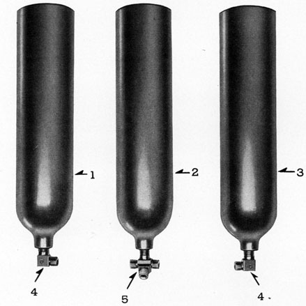
THE AIR FLASKS
Purpose.
The purpose of the three small air flasks is to provide a storage for the compressed air energy that is necessary for the operation of the control units.
Description.
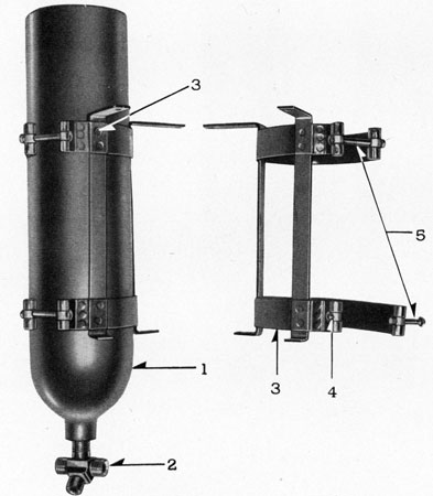
The air flasks are forged steel cylinders, of a uniform wall thickness of 0.152 inch, outside diameter 4.5 inches, length 17.875 inches. Each flask is tested at 5,000 pounds pressure. The working pressure is 2,800 pounds pressure, as in most previous marks of torpedoes. Each flask is mounted in a clamp bracket that is secured around the flask near either end. The clamp brackets in turn support the air flasks in the afterbody. The clamps are joined together around the flasks by clamp bolts, that engage a threaded boss riveted to the end of the clamps. The clamp bolts tend to pull the clamps together around the cylindrical flask. The clamp brackets are fixed in the afterbody by small bolts that pass through holes drilled in the afterbody strengthening rings. The clamp brackets are bolted to the rings, and the air flasks are secured in the brackets. The clamp brackets, with flasks attached, are located abaft the gyro housing, the after ends of the flasks being in contact with the extreme after strengthening ring of the afterbody.
Location of the clamp brackets; locate one flask on either side of the afterbody at the horizontal centerline, the other near the top at vertical centerline, thus forming a triangular pattern around the drive shaft.
The flask openings are threaded to receive pipe fittings, which are screwed, and silver soldered in the flask opening. The pipe fittings for the flasks on the horizontal centerline are 90° angle (elbow) fittings, and the upper center flask is equipped with a three-way fitting to receive the air pipes connecting the three flasks together and a fitting for the main air pipe, which connects the air flasks to the charging and stop valve body. This parallel arrangement of air piping affords a means of charging and discharging the air pressure of the three flasks simultaneously.
Surface Finish.
The interior of the air flasks are shot blasted, to remove any scale on the metal. The cylinder is filled to about one-fourth its capacity with baking varnish, then agitated, so the varnish will cover the entire inner surface: It is then inverted and allowed to drain for 15 minutes. The flask is then placed in an oven and baked at a temperature of 275° F. for 8 hours. The result is a smooth, hard, waterproof finish. The outside of the flasks are cleaned, black air varnish applied and allowed to dry for a period of 12 hours. This finish will prevent deterioration of the flask exterior.
69
Air Flask Disassembly.
1. Remove gyro housing.
2. Remove main air pipe connection at the charging and stop valve body at upper center air flask.
3. Remove air pipe connections, at the upper center, and at the lower flasks.
4. Loosen clamp bolts sufficiently to take the pressure off the clamps around the lower flasks.
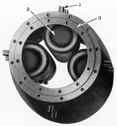
FIGURE 55-5.-Air flasks.
LEGEND
1-Lower starboard air flask.
2-Upper center air flask.
3-Lower port air flask.
4-Pipe fittings lower flasks.
5-3-way fitting center flask.
5. Lower flasks can now be removed from the clamp brackets.
6. Loosen clamp bolts sufficiently to take the pressure off the clamps around the upper center flask.
7. Upper center flask can now be removed from the clamp bracket.
8. Remove clamp brackets from the afterbody strengthening rings.
70
Air Flask Assembly.
1. Inspect clamp brackets for corrosion, remove rust with emery cloth, refinish the surface with black air drying varnish. Secure clamp brackets into afterbody strengthening rings.
2. Drain air flasks, blow dry with low pressure air, inspect, and clear threads, on pipe fittings, with finger die.
3. Replace upper center flask in clamp bracket, locate position by placing afterend of the flask in contact with after strengthening ring.
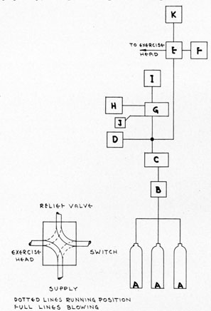
The purpose of the air control system is to provide the power that operates the control units during the run and expels the water ballast from the exercise head at the end of the run.
General Description.
Figure 58-5 is a single line diagram of the air control system. The air storage flasks (A), are mounted in supporting brackets in the afterend of the afterbody, and connected to the stop and charging valve body (B), by copper piping The air flasks are charged through the charging valve, the air is held in the flasks by the stop valve. Both valves are located in body (B) . When the stop valve is opened, the air will flow through the main air pipe to the starting valve, in the starting gear body (C). The starting lever of the starting gear (C), is actuated when the torpedo is fired from the torpedo tube. The action of the starting lever unseats the starting valve, thus admitting high pressure air to the gyrospinning mechanism (D) , which gives the gyro its spin. High pressure air starts the motor through the four-way valve (E), and
the motor switch (F). High pressure air flows to the reducing valve (G), where the pressure is reduced to 400 pounds and delivered to the gyrosteering engine (H), the depth steering engine (I), and the hydraulic cylinder of the motor control unit (J). For exercise runs, the four-way valve (E), is initially set so the air will flow through it to the motor switch (F). The function of the relief valve (K) is to hold the pressure on the motor switch after the four-way valve has been tripped until the pressure has dropped to 400 pounds. The motor switch will then open very quickly, thus preventing the burning of the contacts, and providing a time delay in which
the exercise head can blow. Simultaneously with the closing of the air line to the motor switch, the four-way valve will open the air line to the exercise head. This will allow the remainder of the air pressure in the flasks to exhaust into the exercise head, and expel the water ballast. When preparing a war shot the four-way valve is removed and the motor switch is connected directly to the starting gear.
The above is a general description of the air control system. A detailed study of the control units is necessary for competent maintenance and operation.
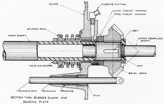
AFTERBODY BEARING PLATE
The afterbody bearing plate is made of cast bronze, machined out on forward side where it seats on a round rubber gasket against the joint ring and is held in place by 12 studs. An oilite bushing is pressed into the bearing plate to provide a bearing and opening for the main
73
shaft. The two rudder rods pass through the bearing plate in stuffing boxes providing for packing and glands. The rudder rods are made tight by pieces of round asbestos packing 3/16-inch diameter, 2 1/16 inches long, adjusted so the rods will move with a 6-pound push.
There is a sylphon diaphragm spring passed over the main shaft and its aft collar is soldered to the bearing plate. The collar on the forward end of the sylphon is a lap fit with and held against a collar, soldered to the main shaft. The two lapped surfaces are held firmly together by a strong spring and forms a watertight joint between the main shaft and afterbody bearing plate.
The main shaft is a steel tube, and extends back to just aft of the afterbody bearing plate. A short shaft is keyed and shrunk to the tube shaft and extends back to the after propeller through the tail cone. The joint is made watertight by soldering.
Aft of the Oilite bearing in the bearing plate, there is a steel thrust washer, Oilite washer, another steel washer and Oilite washer. Then the forward bevel gear of the tail cone gear assembly. Four keys and a lock nut screwed over the solid shaft against the forward bevel gear holds it in place. There is an Alemite fitting on the bearing plate that provides means for lubricating the sylphon collar and lubricating the bushing, Oilite rings and thrust washers.
To Disassemble Main Shaft and Bearing Plate.
1. Remove tail cone assembly.
2. Disconnect rudder rods from depth control and gyro mechanism.
3. Remove 12 holding studs from bearing plate.
4. Draw main shaft and bearing plate aft with assembled bevel gear and rudder rods and rubber gasket.
5. Remove packing glands from stuffing boxes.
6. Remove packing and rudder rods.
7. Remove lock nut from shaft.
8. Press the forward bevel gear off and remove four keys.
9. Remove two steel thrust washers and two Oilite washers.
10. Remove main shaft.
NOTE.-(a) The Oilite bushing in the bearing is pressed in. (h) The after end of sylphon seal is soldered to the bearing plate. (c) The main shaft is shrunk and keyed to the solid shaft. (a), (b), and (c) above should be disassembled only in case of damage or leaks.
To Assemble Main Shaft and Bearing Plate and Rudder Rods.
1. Put main shaft through bearing plate. Inspect lap shoulder on main shaft and sylphon. Clean and grease. Clean and oil bushing in plate.
2. Put on thrust and oilite washers, in the following sequence: (a) steel thrust, (b) oilite washer, (e) steel thrust, (d) oilite washer.
3. Put four keys on shaft.
4. Press the forward bevel gear in place and secure with lock nut
5. Install rudder rods in place.
6. Install rubber gasket on forward side of bearing plate.
7. Install assembly in afterbody.
8. Secure evenly with 12 studs.
9. Put 11 pieces of 3/16-inch round asbestos packing 2X6 inches long in each stuffing box.
10. Put in packing glands and work packing in until rudder rods move with 6 pounds push.
11. Fill alemite fitting with grease.
74
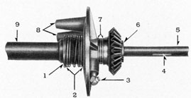
FIGURE 59-5.-Afterbody bulkhead assembly.
LEGEND
1-Sylphon bearing in place on shaft collar.
2-Sylphon spring assembly compressed.
3-90° alemite fitting In place- at angle of 45° with centerline of shaft.
4-Grease retaining groove.
5-After propeller shaft.
6-After propeller gear lock nut.
7-Oilite and steel washers in place against bulkhead bearing flange.
8-Rudder rod bosses.
9-Main drive shaft.
FIGURE 60-5.-Afterbody bulkhead assembly.
75
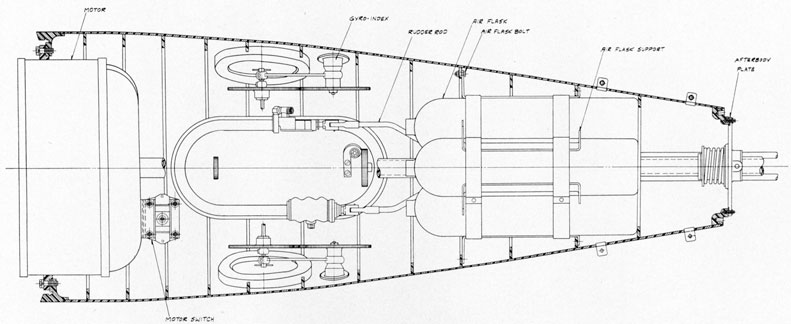
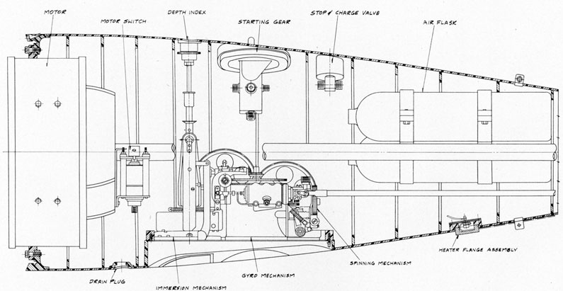
FIGURE 61-5.-Afterbody-General arrangement plan view.