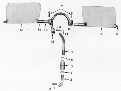
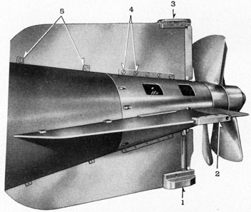
The tail cone assembly comprises the extreme after section of the torpedo and consists of the sheet steel cone with tail vanes, depth and gyro rudders with their adjusting links, battery heater plug, propellers, drive shafts, and idler gears.
The tail cone is a hollow truncated cone of 0.093-inch thick sheet steel. It is made of four segments of formed sheet steel, welded to a joint ring on the forward end and to a bushing flange on the after end. The segments each have two rectangular holes which are used in assembly and for access for lubrication of parts contained within the cone.
On the outer surface, there are four slotted projections, two vertical and two horizontal, at right angles to each other, for securing the vertical and horizontal tail vanes. The outboard bearings for supporting the rudders are installed in rudder shoes attached to the outer edges of the tail vanes. The forward ends of the tail vanes extend forward over the after surface of the afterbody and are secured thereto by means of vane supports.
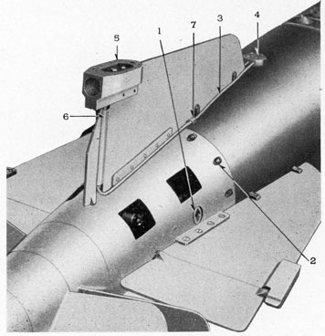
In the lower vertical rudder shoe are the battery heater connections. To the forward end of the cone is welded a 2-inch-wide joint ring of carbon steel, which reinforces the forward end of the cone as well as provides means of centering and attaching the cone to the afterbody joint ring. The joint is made by 12 steel joint screws secured into tapped holes in the afterbody joint ring.
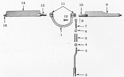
1-Retaining plug, secures idler gear assembly in position.
2-Tail cone joint screws, in place.
3-Copper tubing from heater plug to heater flange.
4-Heater flange in afterbody.
5-Heater plug.
6-Lower vertical vane, split to serve as housing for copper tubing.
7-Tube holding clip.
119
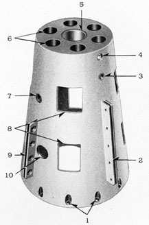
FIGURE 98-10.-Tail cone disassembled.
LEGEND
1-Joint ring screw holes.
2-Tail cone vertical vane supports (note 5 screw holes).
3-Gyro rudder bearing, installed.
4-Alemite fitting, installed.
5-Forward propeller shaft bearing, installed.
6-Holes in after bulkhead, for lightening purposes.
7-Depth rudder bearing, installed.
8-Assembly and lubrication access holes.
9-Tail cone horizontal vane supports (note 4 screw holes).
10-Retaining plug hole for securing idler gear assembly in place.
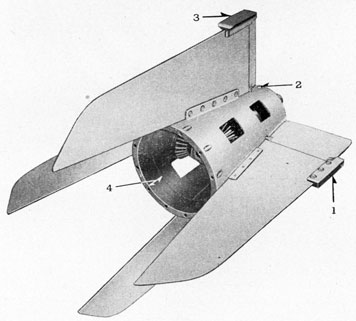
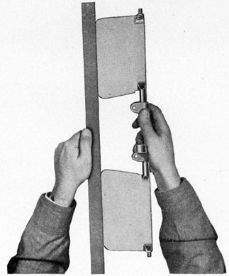
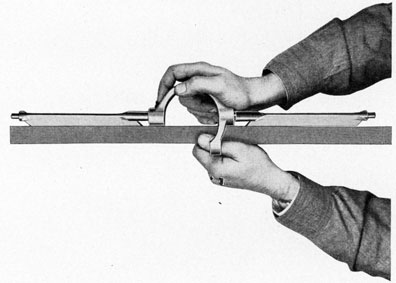
FIGURE 99-10.-Tail cone assembly-ready to be assembled to afterbody.
LEGEND
1-Depth rudder shoe.
2-Alemite fitting for tail cone bearing.
3-Gyro rudder shoe.
4-Shows width of joint ring.
120
To the after end of the cone is welded a steel bushing flange, which reinforces the after end of the cone and also serves as a retainer to center and house the forward propeller shaft bearing. The bushing flange has six 1-inch holes machined in it for reducing the weight of the tail cone. A hole is machined in the flange for insertion of an alemite fitting for the lubrication of the forward propeller shaft bearing.
To the inner surface of the cone are welded suitably machined steel blocks, which serve as supports, for the inboard gyro and depth rudder bearings, and supports for the ends of the idler gear shaft.
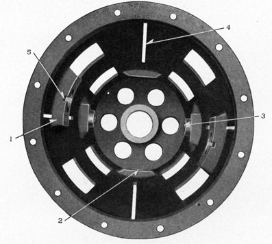
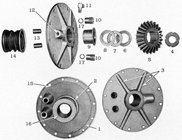
FIGURE 100-10.-Interior of tail cone.
LEGEND
1-Bearing support for idler gear shaft, welded to interior.
2-Bearing support for gyro rudder welded to interior.
3-Bearing support for depth rudder welded to interior.
4-Split portion of tail cone for insertion of vanes,
5-Groove for steel pin on bearing cap.
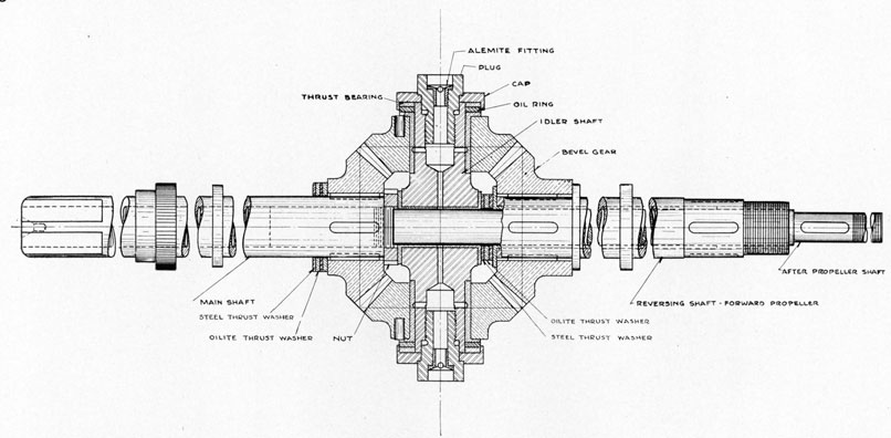
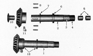
Idler Gear Assembly.
The idler gear assembly is located in the tail cone and serves to obtain clockwise rotation of the forward propeller while the after propeller rotates counterclockwise.
The after propeller shaft is a short solid shaft secured into the hollow main drive shaft with one key. It rotates in a counterclockwise direction, the same as the main drive shaft. By means of four bevel gears of the same size the forward propeller is caused to rotate in a reversed or clockwise direction.
The bevel gears have 24 teeth and are of cast manganese bronze suitably machined to dimension. The gears are cast, using patterns cut with standard gear cutting equipment. The gears upon cooling in the molds shrink slightly and do not conform to the standard gear tooth
121
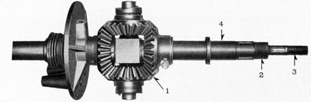
FIGURE 101-10.-Idler gear assembly.
122
size. There is no machining on the teeth of the gears subsequent to casting, except that all burrs and high spots are removed before assembly. This means that the gears cannot be used if a standard cut gear is placed in the assembly. The only machining operations performed on the gears are the boring of the hubs, and the broaching of the keyways on the forward and after bevel gears. The upper and lower idler gears have a straight smooth bore for insertion of an oilite bearing.
FIGURE 102-10.-Complete idler gear assembly on shaft.
LEGEND
1-Gears assembled.
2-Forward propeller shaft thread for propeller lock nut.
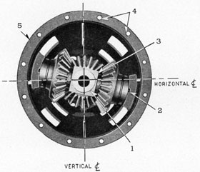
FIGURE 103-10.-Interior of tail cone showing idler gears in position.
LEGEND
1-Crosshead bearing.
2-Bearing cap pins in bearing support grooves.
3-Crosshead.
4-Tail joint ring holes showing spacing-12 holes.
5-Joint ring face-showing thickness-note position of idler gear assembly in cone.
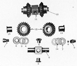
The forward bevel gear is keyed directly to the main drive shaft and secured in position with a lock nut threaded on the after propeller shaft. Thrust bearings of oilite and steel are placed between the hub of this gear and the afterbody bulkhead. The rotation of the forward bevel drive gear imparts rotation to the upper and lower idler gears, which in turn rotate the after bevel gear in a clockwise direction.
The idler gears have flanged Oilite bearings and are mounted on a hardened tool-steel crosshead. The torque supplied to the idler-gear assembly causes an outward thrust of the two
123
idler gears, which are transmitted to a steel and an Oilite thrust bearing to the bearing cups holding the bearings in place. The bearing cups are supported by the bearing supports welded to the interior of the tail cone, thus the outward thrust is transmitted to the tail cone. The entire idler-gear assembly is secured in place by means of retaining plugs screwed into the ends of the crosshead shaft from the outside of the cone. The retaining plugs and crosshead shaft also serve as a grease reservoir for the lubrication of the idler gear bearings and the after propeller shaft bearings in the crosshead. Lubrication is accomplished by means of an Alemite fitting secured in the outer end of the retaining plug.
The after bevel gear is keyed to a short, hollow shaft on which is mounted the forward propeller. The gear is pressed back flush with a stop collar on the propeller shaft.
The forward propeller shaft runs in a flanged Oilite bearing in the tail bulkhead and rides on another flanged Oilite bearing placed between the forward and after propeller shafts. This bearing is at the forward end of the forward propeller shaft, and is subject to extra loads because of the opposite directions of rotation of the two propeller shafts. The two bearings in the after end of the forward propeller shaft likewise are subject to extra loads because of the two opposite directions of rotation of the two shafts. Ahead of the flanged bearing between shafts are Oilite and steel thrust bearings to transmit thrust to the crosshead and thence to the tail cone.
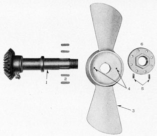
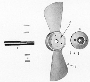
Propellers.
The propellers are made of cast manganese bronze, ground to size and polished. The propeller dimensions are as follows:
Attention is directed to the fact that by variable pitch it is not meant that the propeller blades are free to be moved or adjusted on the hub; rather, the term means that the pitch is not a constant value from the center of the propeller to the outside tip of the blades. The propellers have a true pitch outward to the tips of the blades from the centers, which are approximately 5 inches outside of the hub on both blades of the forward propeller. The after propeller has a true pitch with the centers approximately 3 inches outside of the hub.
A straight bore is machined in the central body of each propeller to fit the shaft to which it is keyed. Four keyways are machined in the bore of each propeller hub for securing to the propeller shafts.
The forward propeller is locked to the shaft by means of a flanged lock nut. The flange has eight holes in it to allow for proper alignment with two holes in the propeller hub and for insertion of two lock screws to secure the lock nut in place. The lock nut has left-hand thread which serves to tighten the lock nut on the threads as the propeller rotates in a clockwise direction.
1-After propeller shaft.
2-Keys for propeller shaft (9).
3-After propeller.
4-Lock screws.
5-Lock nut.
6-Lock screwholes in propeller hub.
The after propeller is locked to the shaft by means of a conical lock nut having two holes for insertion of two lock screws when the holes are lined up with a pair of the six holes machined in the hub of the after propeller. The lock nut has a right-hand thread which serves to keep the nut tightened as the propeller rotates in a counterclockwise direction.
The thrust from the forward propeller is transmitted to the crosshead by the thrust bearings on the after side, and thence to the tail cone. The thrust from the after propeller is transmitted through a flanged thrust bearing on the forward side of the crosshead to the afterbody bulkhead. The towing thrust from the forward propeller is transmitted from the after collar of the forward propeller shaft to the flanged bearing and then to the tail bulkhead. The towing thrust from the after propeller shaft is transmitted through the flanged thrust bearing on the forward side of the crosshead and then to the tail cone.
125
Propeller Lock.
The propeller lock is of cast manganese bronze machined to size; the lock consists of two short fingers which straddle one blade, and the lower end of the lock bears on the other propeller blade preventing rotation of the propellers. Attention is directed to the beveled edge of the lock, which must lie flush against the blade when in the proper position. Also, when the lock is placed in position it must be secured with a short piece of line through the small holes in the fingers. This prevents the propeller lock from sliding or being thrown off the propellers should they be rotated.
Directly behind the tail vanes are the gyro and depth rudders which are secured inside the tail cone to their respective horseshoe-shaped rocker yokes. Rudder rods are attached to the gyro and depth rudder rocker yokes to transmit the action of the gyro and depth engines in changing the azimuth or depth of the torpedo when under way. On each rudder rod there is a turnbuckle with a lock nut on each end. These turnbuckles are used to adjust the rudders.
Rudder Clamps.
As a means of locking vertical rudders for a circular run the yoke for the vertical rudders will have installed a pad containing two radially drilled holes equally spaced from the vertical centerline of the yoke. On the inside of the tail cone and radially opposite the pad on the yoke is fastened a boss which contains a threaded hole in the center. The tail cone is drilled in the wake of this threaded hole. During normal running the vertical yoke swings in the usual manner. To lock the rudder a locking screw is threaded into the tail cone boss. The teat end of the locking screw enters one of the drilled holes in the vertical yoke pad, the rudder being pushed by hand to bring the hole and teat in line. With the screw finally set down the rudder is locked. The two holes on the yoke permit locking with either right or left rudder.
Complete Disassembly of the Tail.
1. Remove after propeller lock nut lock screws.
2. Remove after propeller lock nut.
3. Remove after propeller.
4. Remove four keys.
5. Remove forward propeller lock nut lock screws.
6. Remove forward propeller lock nut.
7. Remove forward propeller.
8. Remove four keys.
9. Remove gyro and depth rudder rod pins.
10. Remove eight screws from afterbody vane supports.
11. Remove four screws and lift terminal cap off heater flange.
12. Disconnect heater wiring at terminal block in heater. flange.
13. Remove twelve screws at tail joint.
14. Remove tail cone assembly from the afterbody. Insert 0.873-inch rod through forward propeller shaft and idler gear assembly as tail cone is being removed-prevents thrust bearings from falling and becoming damaged.
Disassembly of the tail cone.-
1. Loosen square head screws in gyro and depth rudder rocker yokes.
2. Remove horizontal and vertical tail vanes by removing screws in vane supports.
3. Remove gyro and depth rudders from tail cone.
Disassembly of heater connections.-
126
(a) Remove eight screws and lift cap and locating pin from heater plug (lower vertical rudder shoe).
(b) Disconnect cable leads at terminals.
(c) Remove packing gland nut, washer, and rubber packing plug, and withdraw cable.
(d) Remove in the following order.
1. Fiber insulator.
2. Terminal leads-break soldered connection.
3. Two screws and micarta terminal block.
4. Fiber insulator.
(e) Disconnect wires at terminals in heater flange.
(f) If necessary to remove copper tubing from terminal cap or heater plug, saw off tubing, drill out hole, and ream to size for insertion of new tubing.
(g) Remove rudder shoes from vanes.
(h) Press out bearings.
4. Remove two retaining plugs holding idler gear assembly in place.
5. Remove idler gear assembly from tail cone.
Idler gear disassembly.-
(a) Remove bearing cups, Oilite and steel thrust washers.
(b) Remove idler gears from crosshead shafts.
(c) Remove brass pins from idler gear hubs.
(d) Press out flanged Oilite bearings from idler gears.
(e) Press out flanged Oilite bearings from bore of crosshead.
6. Remove forward propeller shaft assembly from tail cone.
Forward propeller shaft disassembly.-
(a) Press out the two Oilite bearings in the after end of the shaft.
(b) Press drive gear off shaft.
(c) Press flanged Oilite bearing from drive gear.
(d) Remove four keys.
7. Disassemble tail cone, if necessary.
Tail cone disassembly.-
(a) Press out flanged Oilite bearing in bulkhead.
(b) Press out gyro and depth rudder bearings.
(c) Remove Alemite fitting, if necessary.
Disassembly of afterbody bulkhead.-
1. Remove packing gland nuts.
2. Remove 12 bulkhead screws.
3. Remove bulkhead and gasket and main shaft assembly.
4. Remove drive gear lock nut.
5. Remove bevel drive gear.
6. Remove four keys.
7. Remove steel and Oilite thrust washers.
8. Remove packing from rudder rod bosses.
9. Press out rudder rod bearings from bosses.
10. Remove alemite fitting, if necessary.
127
Overhaul of the Tail Cone.
The purposes to be accomplished in the periodic overhaul of the tail cone, and the torpedo as a whole, are as follows:
1. Cleaning of all the parts.
2. Examination of all parts for defects.
3. Renewal or repair of defective parts.
4. Proper assembly of the parts.
5. Tests of the individual parts and mechanisms.
6. Tests to check the proper functioning of the tail as an assembled unit.
7. Properly treat the parts to preserve them from deterioration.
The cleaning of all parts in the overhaul operation is by means of gasoline, using a stiff brush or rag. Parts must be blown dry after being cleaned.
After an exercise run or during the periodic overhaul, all parts must be given a thorough examination for defects. Where defective parts are found, they must be renewed rather than repaired, unless the defect is of such a slight nature that repairs can be effected with no impairment to the part. Upon disassembly, parts should be examined for the following: Cracks, pits, rust, corrosion, wear, breakage, burrs, scoring, "wiped bearings", heat discoloration, clipping, etc.
It is especially necessary to check bearings and other vital spots for excessive wear. It is recommended that gaskets be replaced when reassembling the parts, as the gaskets acquire a "set" under compression, and thus lose most of their effectiveness if used again.
All alemite fittings must be removed, cleaned, and checked. The grease passages to the bearings must be thoroughly cleaned to insure proper lubrication of bearings in operation.
All threaded parts, internal or external, should be checked for good threads. Use taps and dies to clean out threads and remove burrs. Inspect lapped surfaces and check with bluing, and relap if necessary.
Oilite bearings are used throughout the tail. These bearings are porous bronze filled with oil. Therefore, when these bearings are stored they should be stored in wax paper, cellophane, tin, or sheet metal containers or under oil. If a bearing becomes scored, the bearing should be replaced, as the pores of the material will have been closed, thus sealing the oil from the bearing surface.
It is especially important that the tail vanes be accurately assembled and adjusted for proper angularity. The vanes must be adjusted exactly 90° apart to insure a true run of the torpedo.
In assembly, check smoothness of operation (clearances) of the idler gear assembly and also the gyro and depth rudder assemblies. The action must be free and smooth. Sticking or hard movement of these assemblies indicate insufficient clearances or misalignment or some foreign substance in the assemblies.
Complete Assembly of the Tail.
Tail cone assembly.-
1. Insert two gyro rudder Oilite bearings.
2. File off any protruding bearings to fit contour of cone.
3. Line ream gyro rudder Oilite bearings to 0.375 inch.
4. Insert two depth-rudder Oilite hearings.
5. File off any protruding bearings to fit contour of cone.
6. Line ream depth rudder Oilite bearings to 0.5625 inch. 7. Insert forward propeller shaft Oilite bearing in bulkhead.
NOTE.-Bearing flange to be on inside of tail cone.
128
8. Drill 1/8 inch hole through bearing for grease inlet.
9. Insert alemite fitting.
Forward propeller shaft assembly.-
1. Place four keys in keyways on forward end of shaft.
2. Press bevel drive gear on shaft.
NOTE.-Gear must be tight against collar on shaft.
3. Press flanged Oilite bearing into bevel drive gear.
NOTE.-Flange must be tight against gear.
4. Insert two Oilite bearings in after end of shaft.
5. Insert 60° Alemite fitting in bevel drive gear.
NOTE.-Fitting to face aft at an angle of 45° with the centerline of the shaft.
6. Place forward propeller shaft assembly in tail cone bearing.
Idler gear assembly.-
1. Insert two flanged Oilite bearings in bore of crosshead.
NOTE.-Flanges must be tight against crosshead.
2. Insert a flanged Oilite bearing in each idler gear.
NOTE.-Flanges must be tight against gear. Notches in flange must line up with hole in gear.
3. Drive 1/4-inch brass pin in hub of gear. This locks the bearing in place. The bearing must rotate on the crosshead shaft.
4. Place steel thrust bearing on bearing flange.
5. Place Oilite thrust bearing on steel bearing.
6. Place bearing cup on Oilite thrust washer.
7. Place tail cone in vise and secure by means of protruding propeller shaft.
8. Line up letter "A" on forward propeller drive gear with one of the retaining plus holes in the tail cone.
9. Place three thrust washers on the flange of the forward propeller bearing in the following order: (a) Steel; (b) Oilite; (c) Steel.
10. Install idler gear assembly in tail cone. Letter "A" on idler gear to line up with letter "A" on the forward propeller drive gear.
NOTE.-Pins on bearing cups to fit in grooves of bearing supports.
11. Insert and secure two retaining plugs to hold idler gear assembly in place.
12. Insert Alemite fitting in each retaining plug.
13. Check entire assembly for freedom of motion (clearances) by rotating forward propeller shaft.
NOTE.-Assembly must be torn down if gears do not turn freely. Check all clearances, and note any defective parts or damaged areas.
14. Check alignment of crosshead bearing and forward propeller shaft bearings with 0.873-inch alignment checking bar.
Gyro and depth rudder assembly.-
1. Insert squared ends of rudders in rocker yoke.
2. Check alignment of rudders along the trailing edges and on the surface.
NOTE.-Accomplish alignment by bending rocker yoke. Bend while cold.
3. Insert rudder rod connecting pin in rocker yoke from inside of yoke on the gyro rudders and from the outside in the case of the depth rudders.
4. insert two square head screws in split portion of yoke.
1-Retaining plug. Secures idler gun assembly in cone.
2-Bearing cap.
3-Oilite thrust washer.
4-Steel thrust washer.
5-Crosshead flanged Oilite bearings.
6-Grease holes to lubricate idler gear bearings.
7-Bearing cap pin-fits in groove of bearing support.
8-Alemite fitting-screws in retaining plug.
9-Square socket in retaining plug.
10-Idler gear assembly complete-retaining plugs in position.
11-Crosshead bearings in position.
12-Idler gear.
13-Idler gear flanged Oilite bearing.
130
5. Place rocker yokes inside tail cone and insert rudder from outside of tail cone.
NOTE.-Figure 116-10 shows the rocker yokes in position: Open side of gyro rocker yoke faces port side and open side of depth rocker yoke faces the bottom.
6. Secure the square head clamp screws.
7. Assemble rudder rod connections.
(a) Screw lock nuts on both halves of rudder rod connection.
(b) Screw both halves of rudder rod connection into turnbuckle.
NOTE.-Turnbuckle has a left and a right-hand thread.
(c) Place after ends of rudder rod connections on rocker yoke pins and secure with cotter pins.
Rudder shoe assembly-horizontal and the upper vertical vane shoes.-
1. Insert Oilite bearings in shoes.
2. Hand ream to 0.3125- inch on the horizontal vane shoes.
3. Hand ream to 0.250- inch on the upper vertical vane shoe.
4. Secure rudder shoes to vanes with three screws.
Lower vertical vane rudder shoe assembly.-
1. Insert Oilite bearing in shoe.
2. Hand ream to 0.250 inch.
3. Insert copper tubing and solder, in case new tubing is used.
FIGURE 108-10.-Depth rudder assembly showing all parts disassembled.
LEGEND
1-Rudder rod connection pin.
2-Cotter pin.
3-Rudder rod connection-forward half.
NOTE.-Right-hand thread.
4-Turnbuckle lock nut-forward nut.
NOTE.-Right-hand thread.
5-Turnbuckle.
NOTE.-Right- and left-hand threads.
6-Turnbuckle lock nuts-after ends.
NOTE.- Left-hand thread.
7-Rudder rod connection-after half.
NOTE.-Left hand thread.
FIGURE 110-10.-Checking alignment of trailing edge.
518463-43-10
132
4. Secure rudder shoe to vane with two screws.
Vane assembly.-
1. Assemble gyro rudder vanes to tail cone supports and secure with five screws. Place tube holding clip, under lower vane when assembling it.
2. Assemble depth rudder vanes to tail cone supports and secure with four screws.
3. Check uniformity of gap between vanes and rudders. Rudders must he free to swing throughout full throws in both directions.
NOTE.-Vanes must be moved forward if too close to rudders.
4. Check vanes for angularity. Vanes are located 90° apart.
Afterbody Bulkhead Assembly.
1. Insert two Oilite bearings in rudder rod bosses.
2. Peen ends of bearings to form a slight flange.
FIGURE 111-10.-Checking alignment of rudder surfaces.
3. Hand ream bearings to 0.500 inch.
4. Insert flanged Oilite bearing.
NOTE.-Flange to be flush with bulkhead. Flange to be on after side of bulkhead.
5. Drill 1/8-inch hole through bearing for grease inlet.
6. Insert 45° Alemite fitting.
7. Drill 1/8-inch hole through bearing flange into bulkhead.
8. Drive 1/8-inch brass pin into bulkhead.
9. Solder sylphon and spring assembly to bulkhead.
10. Lap the seat on the collar of the main drive shaft.
11. Lap sylphon bearing seat.
12. Check lapped surfaces with bluing.
13. Place sylphon bearing on shaft collar and finish lap with oil and graphite.
14. Test afterbody bulkhead assembly for leaks in the sylphon and for porosity of bulkhead. 15. Place sylphon bearing assembly on main shaft collar.
133
16. Place four thrust washers on flange of bulkhead bearing in the following order: (1) Steel, (2) Oilite, (3) Steel, (4) Oilite.
17. Place four keys in keyways.
18. Place after propeller bevel drive gear on shaft.
19. Secure bevel gear with lock nut. NOTE.-DO not force lock nut too tightly.
20. Place gasket on bulkhead.
21. Secure bulkhead on afterbody with 12 screws.
22. Insert rudder rods in bulkhead.
23. Insert 11 pieces of 3/16 inch diameter by 2 1/16 inches long packing.
FIGURE 112-10.-Afterbody bulkhead assembly showing all parts disassembled.
LEGEND
11-90° Alemite fitting.
12-Alemite fitting hole-grease passage to bearing.
13-Rudder rod oilite bearings.
14-Sylphon spring assembly.
a. Sylphon.
b. Spring.
c. Bearing.
15-Bulkhead bolt holes.
16-Bearing seat.
17-Rudder rod packing (11 pieces per rod-1 piece shown).
NOTE.-Grease packing before inserting. Stagger joints when inserting.
24. Insert packing glands, secure. Move rods while tightening glands.
25. Adjust gland nut compression so that rudder rods will just slide at 6 pounds pull.
Afterbody Bulkhead Test for Leakage and Porosity.
1. Secure bulkhead to adapter plate. Use good gasket.
2. Secure plug on sylphon with washer in position on bearing.
3. Bolt adapter plate to test tank flange.
4. Remove gland nuts and plug with 3/4-inch plugs.
5. Apply 150 pounds per square inch hydrostatic pressure.
6. Check sylphon for leaks and bulkhead for porosity.
134
Tail Cone Assembly to Afterbody.
1. Insert 0.873-inch rod through idler gear assembly and forward propeller shaft.
NOTE.-Rod serves to hold crosshead thrust washers during assembly.
2. Assemble tail cone to afterbody. Line up letter "A" on after propeller drive gear with letter "A" on idler gear.
NOTE.-Idler gear has two letter "A's" stamped 180° apart.
3. Secure tail cone with 12 square head screws.
4. Secure two screws in each tail vane at afterbody vane supports.
5. Check assembly for freedom of motion (clearances) by rotating main drive shaft. Gears must move freely, otherwise assembly must be torn down and the cause determined.
6. Assemble rudder rods and rudder rod connections with connection pins, and secure with cotter pin.
FIGURE 113-10.-Tail cone assembly on afterbody.
LEGEND
4-Screws securing vane to tail cone support.
5-Method of securing forward end of vanes to afterbody.
Heater Assembly.
1. Insert copper tubing in split portion of vane and bend forward at cone surface. Place tubing under holding clip secured by vane.
2. Insert ends of tubing in terminal cap and solder in place.
3. Insert wiring in copper tubing.
4. Attach wires to terminals of heater flange.
5. Secure terminal cap to afterbody with four screws.
6. Place fiber insulator in shoe.
7. Solder terminal leads to copper connectors.
135
8. Secure two copper connectors to terminal block with two screws and nuts.
9. Place micarta terminal block in shoe and secure with two screws.
10. Insert No. 18 rubber-covered duplex cable, 18-inches long, in after end of shoe.
11. Insert rubber packing plug, washer, and secure with packing gland nut.
12. Attach cable leads to terminals.
13. Put fiber insulator in place.
14. Place gasket and cap and secure with eight screws. Insert locating pin when assembling cap.
FORWARD PROPELLER ASSEMBLY
AFTER PROPELLER ASSEMBLY
1. Place four keys in keyways.
1. Place four keys in keyways.
2. Place forward propeller on shaft.
2. Place after propeller on shaft.
3. Secure lock nut on propeller shaft.
3. Secure lock nut on propeller shaft.
Nut has a left-hand thread.
Nut has a right-hand thread.
4. Insert lock nut lock screws.
4. Insert lock nut lock screws.
5. Place the propeller lock and secure in place.1
Lubrication is accomplished with grease, specifications of which are Beacon Lubricant No. 285, Standard Oil of New Jersey. It is important to bear in mind that no piece of machinery will continue to operate unless the moving parts are well lubricated. It is imperative that an ample supply of lubricant be furnished all bearings before a run. Access to all fittings is possible through the openings in the tail cone.
Lubrication of the tail cone assembly is accomplished by means of Alemite grease fittings and a grease gun. Lubrication is required for the following:
(1) Forward propeller shaft bearing, located in the tail cone flange bushing. Plain Alemite fitting for this bearing is located on the top centerline of the tail cone just forward of the propellers.
(2) Forward propeller shaft bearing. A 60° Alemite fitting is installed in the hub of the gear. Fitting to face aft at an angle of 45° with the centerline of the shaft. Grease at this point also travels aft along the after propeller shaft to lubricate the two bearings in the forward propeller shaft.
(3) Two idler gear bearings, located on the crosshead of the idler gear assembly. Plain Alemite fittings are installed in each of the retaining plugs holding the idler gear assembly in place.
(4) The afterbody bearing and sylphon in the afterbody bulkhead. A 45° Alemite fitting is installed in the boss on the after side of the bulkhead. This point must be kept well supplied with grease, as the sylphon must be kept packed with grease to serve as a seal in preventing sea water from entering the afterbody.
Attention is directed to item No. 2 on the above list. This fitting must be well supplied with grease in order for sufficient grease to be forced back to the two bearings inside the forward propeller shaft. These bearings and the flanged oilite bearing at the forward end of the shaft suffer extra loads because of the opposite directions of rotation of the forward and the after propeller shafts.
1 Step 5 refers to both forward and after propeller assembly.
136
Test Procedures on Tail Cone Assembly.
1. Check alignment of upper vertical tail vane with centerline of afterbody. With tail assembled to afterbody and the entire assembly held in place in a cradle, place a straightedge along the upper vertical tail vane. The straightedge should be in line with depth index operating spindle and the center of the top joint ring hole.
2. Check angularity of tail vanes. Tail vanes should be 90° apart as determined by means of a tail square.
3. Check gyro and depth rudders for freedom of movement. Rudders must be free to move to full throw positions on either side of the vanes. Vanes must be moved forward if there is any interference in rudder movement.
4. Check gyro and depth rudders for play. After assembly of tail to the afterbody, the loose play in the rudders should be practically nil when the turnbuckle connections, the rudder rod connections, and the rudder rod to the steering and depth engines have been properly made.
5. Check gyro rudders for full throw settings. By means of tool No. 44, vernier gage, the full right and left rudder throw must be the same. The full throw of the rudders must be the same on the upper and the lower gyro rudders. For this test the gyro engine is connected to a source of air at 400 pounds per square inch pressure. Full right and left throw should be approximately 0.2 inch.
6. Check depth rudders for proper throw. For this test the depth engine is connected to a source of air at 400 pounds per square inch pressure. With the depth engine at zero setting, the top face of the depth rudder should be in line with the 1 1/2 (down) mark on the tail cone scale. Full "Up" position must be 1 unit above 0 mark. Full "Down" position must be 4 units below 0 mark on tail cone. Adjust turnbuckle until settings are correct.
Assembly and Alining Fixtures.
I. Check alignment of main drive shaft and after propeller shaft assembly.-Place shaft assembly between centers on alining bar and adjust indicator to touch. Turn shaft slowly and note reading on indicator If more than 0.017 out of true, chalk mark highest point and straighten in press.
Use shaft straightening press and centers, together with a dial indicator for checking shaft alignment. (Present shaft straightening press and centers now in use for all marks and mod. torpedoes are capable of straightening stock up to 1 3/4 inches in diameter (commercial) and fitted with a special shaft, drawing No. 173726-8 and specials centers, drawing No. 173726-9, together with a dial indicator for checking shaft alignment.)
II. Checking and straightening bent propellers.-This requires the use of a propeller former block, which is a cast-iron block, the sides of which are machined to the correct contour and pitch of the after sides of both forward and after propeller blades. A large spindle on one end carries the hubs to which the propellers are attached when checking for true, which should be done at each overhaul period, whenever necessary due to damage of propellers.
Procedure.-1. Place propeller over hub on former block, locate large steel washer over propeller and spindle, and secure with nut.
2. Bring propeller blade tight up against former block and note if flush with face of block by inserting one thickness of ordinary paper at various points. If the paper can be withdrawn on some points and binds on others, it is evident that the blade is out of true with the forming block. If only a small amount out of true, the condition may be remedied by tapping with a small lead hammer, shimming the high spots between the blade and forming block with lead or copper
137
shims. After straightening a badly bent propeller blade, it should be smoothed with a file and emery cloth.
NOTE.-As a general rule, no attempt should be made to repair a propeller with badly nicked edges. If absolutely imperative to make repairs in the field, it may be possible to machine the nicked portion and effect a repair by brazing in a small section of manganese bronze or by building up of brazing material. The section should be smoothed with a file and emery cloth. Propellers should be replaced by spares from tender stock and the damaged propeller returned to the torpedo station at Newport for repairs.
III. Checking tail vanes for proper alignment.-A tail square with adjustable contact bars, drawing No. 39572, is issued for all marks and modifications. The tail square should be used after transporting or firing and when overhauling torpedoes to ascertain that tail vanes are in proper alignment.
IV. Checking alignment of gyro and depth rudder bearings (inner and outer bearings).-Round alining bars are furnished to check the alignment of the inner and outer gyro and depth rudder bearings. The round bar gages are inserted through the bearings in the rudder shoes, through the bearings in the tail cone, and through the opposite rudder shoe bearings. These bars will indicate at once if the bearings are out of line, noticed by the tightness of the bars in the bearings or by the inability to insert these bars in the bearings at all. Previous tests and adjustments are made to establish the alignment of the upper vertical tail vane with the centerline of the torpedo, and the 90° between tail vanes. Misalignment of the rudder bearings is then obviously in a longitudinal direction, the rudder bearings in the shoes being either too far forward or too far aft of the bearings in the tail cone. This misalignment will be corrected by moving the rudder shoes or the tail vanes themselves to effect perfect alignment.
Round bar for gyro rudder bearings
Round bar for depth rudder bearings
Description, Installation, and Care of Oilite Bearings
The bearings used throughout the tail construction are Oilite bearings. These bearings are made from powdered bronze by briquetting, heat treating, sizing, and impregnating with oil of a nongumming lubricating type.
The application of bearings to the tail construction require press fits from 0.001 to 0.003 inch to insure that the bearings do not move in operation. Due to the relatively soft and porous material in the bearing, there is an average "close-in" of 0.0006 inch per 0.001 inch of press fit in assembly. For this reason sizing tools must be used during the assembly, and in some cases, after assembly. The bearings installed in the tail are to be installed with sizing tools furnished for the purpose, and in the case of the small bearings the sizing is completed by means of hand reamers furnished for the operation. A hand arbor press is used to press in the larger bearings, and in the case of the smaller a block of wood or fiber together with a hammer or mallet are used for the assembly. It is recommended that Oilite bearings be dipped in a good grade of engine oil prior to assembling, thus providing excess oil between the shaft and bearing.
If an Oilite bearing becomes scored in service it must be replaced, because the surface has been "wiped" over, thus closing the pores of the material and sealing the oil inside of the material. For the same reason it is generally not good practice to machine bearing surfaces because of the danger of closing the pores. If in doubt regarding an Oilite bearing it is recommended that the bearing be replaced immediately.
If properly stored, Oilite bearings will retain their oil supply indefinitely. To preserve the impregnated oil, these bearings should be stored in wax paper, cellophane, tin, or sheet-metal containers.
138
Useful tools and devices.
The following tools and devices will be found useful in the disassembly and assembly of tail:
1. Ball peen hammer.
2. Flat mill file.
3. Six fluted line reamers, 0.375 inch diameter.
4. T-wrench with a 5/16-inch square socket.
5. Six fluted line reamers, 0.5625 inch diameter.
6. T-wrench with a 7/16-inch square socket.
7. Hand arbor press.
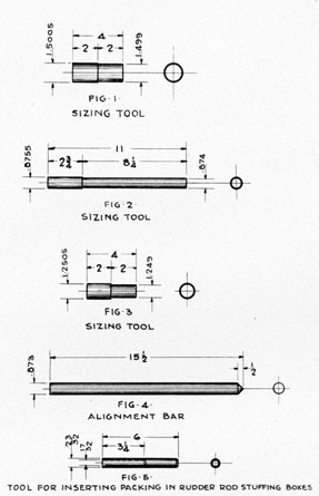
8. Sizing tool-See figure 114 (fig. 1).
9. 1/8-inch straight shank drill.
10. Electric hand drill.
11. Screw driver.
12. 1/2-inch open end wrench.
13. Sizing tool-See figure 114 (fig. 2).
14. Sizing tool-See figure 114 (fig. 3).
15. Machinist's vise.
16. T-wrench with a 5/8-inch square end (retaining plug).
17. Alignment bar-See figure 114 (fig. 4).
18. 24-inch scale (for checking alignment).
19. T-wrench with 1/4-inch square socket.
20. Six fluted hand reamers, 0.3125 inch diameter.
21. Six fluted hand reamers, 0.250 inch diameter.
22. T-wrench with 3/16-inch square socket.
23. Feeler gages.
24. Tail vane angularity measuring tool.
25. Gas torch for soldering.
26. Piano wire for inserting wiring in copper tubing.
27. 1-inch open-end wrench.
28. T-wrench with 3/8-inch square socket.
29. Six fluted hand reamers, 0.500 inch diameter.
30. Cast iron lapping collar for lapping seat on collar on main drive shaft.
31. Cast iron lapping plug for lapping sylphon bearing seat.
32. Test set for testing porosity of bulkhead and for leaks in the sylphon.
33. Tool for inserting packing in rudder rod stuffing boxes-See figure 114 (fig. 5).
34. Spring tension scale, 24 pound scale. 35. Short pieces of pipe, one piece 1 1/2 inch diameter, and one approximately 1/2 inch diameter,
139
FIGURE 114-10.-Special tools for tail cone.
140
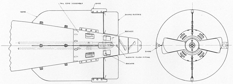
FIGURE 115-10.-Tail cone-plan.
141
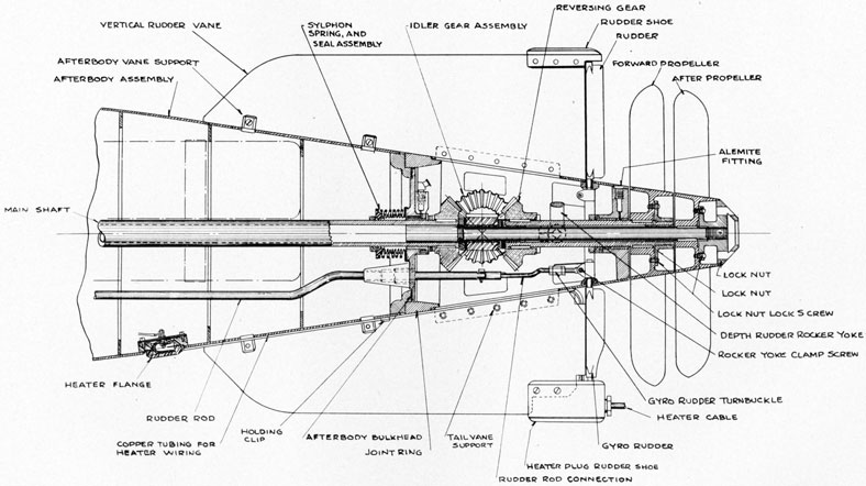
FIGURE 116-10.-Tail cone-elevation.
142
This page is blank.
143
ADJUSTMENTS AND TESTS
Chapter 11. ADJUSTMENTS AND TESTS
144
PRELIMINARY ADJUSTMENTS
Preliminary adjustments are made to ascertain that there are no leaks, and that the various controlling units will function properly as received from overhaul; also to check for coincidence of reference marks together with index dials and pointers for alignments and accuracy. With preliminary adjustments completed, the torpedo is ready for the final adjustments to be made prior to a run.
CAUTION.-Do not invert, acid may spill.
Preliminary adjustments should be made with the torpedo resting on a truck or chocks (with head removed) located under a chain hoist, preferably adjacent to the general use testing panel.
Equipment, tools, and supplies required for use in making preliminary adjustments will be covered in "Glossary." (See ch. 13.)
1. Place torpedo in chock, right side up.
2. Put on propeller lock.
3. Put on the starting lever lock.
4. Remove all handhole plates. (Tool No. 48-410.)
Lubrication.
5. Before the torpedo is ready for firing, see that sufficient lubrication is given to the following places (use Beacon lubrication No. 285 Standard Oil Co. of New Jersey):
(a) Motor bearings (two cups). This is done on the no-load test (see step 77). Slowly screw down caps on grease cups until grease appears along shaft beside bearing. This should be done before and after running the motor, turning propellers by hand and adjusting caps simultaneously.
(b) Bearings in the governor body, and governor gears. See that the gear teeth mesh properly and do not bottom.
(c) Bearings in crosshead body. This is done by putting grease into the retaining plugs from outside of the tail cone. Special care must be given to this bearing, as the bushings inside the idler gear hubs and the crosshead are subjected to high stresses during a run. Improper lubrication of the crosshead will result in binding of the idler gears, and possible binding between the crosshead bushings and after propeller shaft.
(d) The concentric bearing surface between the forward and after propeller shafts. The Alemite fitting is just aft of the hub of the bevel gear or reversing gear on the forward propeller shaft.
(e) Tail cone bearing. This is lubricated through small hole in the tail cone.
(f) After body bulkhead. An Alemite fitting is located just aft of the bulkhead. This takes a considerable quantity of grease, as the interior of the sylphon spring must be completely filled and the bearing in the bulkhead must be properly lubricated.
(g) It is a good practice to grease the tooth surfaces of the bevel gears with Beacon Lubricant No. 285. -
Batteries and Battery Compartment.
6. See that the batteries are installed correctly in the battery compartment. The 12 wing nuts should be tight, and the battery holding bolts should be secured.
7. Attach a source of voltage to the outside heater circuit wires. Apply approximately 230 volts and note rise in temperature of the heater units. Check to see that all jumper connections between units are secure. See that the heater circuit is complete. Reach in through the
145
aft handhole in the battery compartment and close the heaters relay by hand. Use rubber gloves or be careful not to touch live parts.
8. See that control circuit and thermostats are connected properly. Note that six cells are connected into the control line. Determine the temperature, and note that this circuit will close the relay when the temperature is not more than 82.4° F.
9. Note that the rubber bags are installed (for exercise runs only) in place of the plugs and that all vent plugs are tight.
10. Battery voltage and specific gravity must be tested. The specific gravity can be read in a few cells. Especially check the gravity of the control circuit cells, as these are usually the lowest due to the constant drain by the control circuit. The gravity should be between 1.270 and 1.285.
11. (a) Voltage of the 80 cells can be read by applying the voltmeter leads to the two of t battery terminals (use caution not to touch terminals by hand).
(b) If the voltmeter is connected to the socket connection-
1. Close stop valve.
2. Check to see that starting lever is forward.
3. Remove charging plug and washer.
4. Note that the motor switch is open, and that there are no jumpers across the terminals.
5. Close hand switch (turn counter-clockwise).
6. Insert voltmeter leads into socket connection using standard Navy plug.
7. Voltage should be between 168 and 172 volts (2.1, volts per cell).
8. Disconnect plug.
9. Open hand switch (clockwise)-important!
10. Replace charging plug-open stop valve.
12. See that the battery compartment is clean and dry. Wipe the top of all batteries with a clean dry rag. See that all batteries are tight in their cases.
13. Note that bulkhead poppet valve is set properly, and will open easily.
14. Note that relay is connected properly.
15. Check cable glands and gland nuts-see that they are tight.
16. Note that hand switch is open. Turn clockwise and back 1/2 turn.
17. Note that socket connection is correct. See that positive is connected to positive battery lead, minus to minus. The positive side of the socket should be aft.
18. Check the leads from battery to motor. Check all battery jumper leads, especially forward lead connecting two parallel rows of batteries in series (as this is often removed during repair to protect the operator from full voltage in case of shock).
Afterbody.
19. Remove the drain plug. Note that the afterbody is clean and dry. Note condition of washer, and replace the drain plug, securing it tightly.
20. Disconnect the rudder rods from the steering engines. Pull the rods back and forth by hand and see that they move evenly through the packing glands. It should take approximately 6 pounds to move the rods through the glands. If it takes less force, tighten up on the gland nuts.
21. Note that there is a minimum of end play in the rudder rod assembly, and that the rudders move freely, but without end play, in their bearings.
22. Connect rudder rods to steering engines.
146
23. Note the contact points, to see if they are in good condition and that there is no jumper across the motor switch.
24. Note that terminal cap for heater wires is screwed tightly to the heater flange, and that the copper tubing is soldered securely to the terminal cap.
25. Close stop valve.
26. Move starting lever to open position several times. By placing an open end wrench on the lever, the operator should be able to move it by hand. If there is undue friction in movement the valve is not operating correctly. In returning to closed position, depress spring loaded retaining pin.
Observe the action of the retaining pin which holds the lever secure in the fired position. See that it moves freely and without friction.
Warning.-Do not attempt to force the lever forward against the pin. Hold the pin in, against the spring, with a screw driver, and then move the starting lever forward. Leave starting lever in forward position, and replace starting lever lock.
Tail Cone.
27. See that the following places are lubricated:
(a) Cross head idler gear assembly (2 places).
(b) Forward propeller shaft.
(c) Tail bulkhead.
(d) Afterbody bulkhead and sylphon.
(e) Idler gears. Use Beacon Lubricant Nos 285, Standard Oil Co. of N. J., on all.
In preliminary adjustment it will not be necessary to measure the alignment of the vanes, or rudders, if this has been done recently on overhaul. However, if it is obvious that a vane or rudder has been damaged during transit or in handling, it should be straightened (see section on test procedure on tail assembly, ch. 10).
28. See that propellers are correctly placed on shaft. They should cross at 12 o'clock and 3 o'clock positions. Note that after propeller lock nut is secure, and that the screws that hold it to the after propeller are tight. If propellers do not cut as above, realine idler gears.
29. Note rudder rod adjusting mechanism. Lock nuts should be tight against turnbuckles. See that square-headed screws on yokes are tight.
30. There should be a minimum of end play in the rudder rod assembly.
31. Rudders should be free to turn, and should have a minimum of end play in their bearings. (Rudder throws are covered in the adjustment of the horizontal and gyro steering engines.)
32. The electrical connections in the lower vertical vane shoe must be tight.
(a) Remove the cap, and see that the micarta terminal block is secure and that the connections are tight.
(b) The shoe should be filled with paraffin to waterproof it.
(c) Replace the cap and eight screws, and tighten gland nut.
33. The copper tubing must be secured to the back of the vane, and must be tight against the outside of the afterbody.
34. Turn propellers by hand. They should turn freely, if the bearings and gears are properly lubricated.
35. See that retaining plugs are secure in the crosshead.
36. See all vane securing screws are tight.
147
Check Adjustments and Action of Depth Mechanism and Depth Index.
37. Test atmospheric chamber for leaks, using test fixture, drawing No. 173758. (Nom-Inboard end of adapter must be machined to clear diaphragm plate lock nut; insertion of the wrong adapter will result in a bent diaphragm lever or connecting linkage (tool Nos. 92, 11, 461, 48, 410, 409).
38. Remove plug in atmospheric chamber (tool No. 11).
39. Install test connection with gauge in atmospheric chamber.
40. Connect test pump, pump to 15 pounds per square inch, and check for leaks; should hold 15 pounds ± 0 for 5 minutes.
41. Remove test pump and connections.
NOTE.-If atmospheric chamber will not hold 15 pounds pressure for 5 minutes, renew diaphragm and repeat test. In renewing diaphragm, inspect the six holes in diaphragm ring to insure that they are clear to allow free passage of water into the immersion casing. The detailed procedure is covered under the overhaul of the depth mechanism. WARNING: Care should be taken to hold the diaphragm plate securely when "backing off" or "setting up" on the diaphragm plate lock nut to preclude any possibility of bending the diaphragm lever or the diaphragm lever and pendulum lever shaft. The movement of the depth control valve stem as compared to the diaphragm lever is 18:1. Slight deformation of lever will be greatly magnified on the depth steering engine and adversely affect the torpedo's run.
44. Remove charging valve plug and washer (tools Nos. 13-14).
45. Insert wing nut charging connection in charging valve bushing and secure safety strap. Remove aft handhole plate from midship section (battery compartment) main motor operating compartment; check to see that battery switch is open (rotated fully clockwise and back one-half turn).
46. Open valve on charging panel and build up air pressure in charging line to 1,500 pounds per square inch.
47. Check governor port alignment and make sure it is off "zero position." Throw starting lever to the rear, admitting air to the reducing valve where it is reduced to 400 pounds per square inch to operate steering engines.
48. With transportation pin in place, air on the engine, note that scribe marks on depth engine valve stem and stop are aligned. If not, loosen clamp screw and turn knurled nut to align, being careful to leave the hole, drilled through the knurled nut in a horizontal plane. This places the control valve and stem pin in the correct position-the position in which it will not drop down and bind. Set up on the clamp screw (tool No. 246).
49. With transportation pin in place, air on the engine, depth index on "zero," verify neutral rudder throw. This should be 1 1/2 down from the zero graduation on the tail. If not, adjust rudder connection in tail.
50. Remove transportation pin (tool No. 49).
51. Close stop valve on charging panel and check alignment of the top of both rudders with center lines scribed on tail cone. if not in alignment, remedy condition before proceeding with rudder tests.
52. Open stop valve on charging panel. Build up air pressure to 1,500 pounds per square inch. Move pendulum by hand both ways against stops. The total rudder throw, full up to full down, should be five divisions of the graduations on the tail (1 up and 4 down). If this value is not obtained, find the interference and remedy before proceeding with the next step. If unable to get the full throw, check pendulum clearance and see if there is any obstruction to its free movement, or any obstruction in the steering line, afterbody or tail cone. If the proper
518463-43-11
148
division of rudder increments is not obtained, the adjustment can be made in the tail by turning the turnbuckle.
53. Install hoisting strap and hoist the torpedo clear of truck.
54. Install screw hook in end of diaphragm plate lock nut and hang 14-pound weight.
55. Place two spirit levels, one on the top center of the battery compartment and one on the horizontal tail vane, and level torpedo.
56. By turning the depth index, apply tension on the depth spring until the center line scribed on the depth engine valve connecting rod is in line with the scribe mark on the valve stop arm; if the depth index does not read 10 feet with valve in the above position, disengage the spring loaded side gear spindle from the socket in the adjusting screw head (on the housing), set depth index on 10 feet and reengage the spring loaded spindle in socket (tool No. 472).
57. Verify neutral rudder throws with the weight attached, afterbody level, air on engine, set depth index on "Zero" and back on ten feet: Note that scribe on. connecting rod and stop are again in alignment under the above-mentioned conditions.
58. Remove weight and unscrew hook from diaphragm plate lock nut (tool No. 411A).
59. Replace access plug and washer (check to see that washer is in good condition; if not anneal or renew) (tool No. 11).
60. Set depth index at zero (tool No. 135A).
61. Test sensitiveness of pendulum by tilting torpedo: Pendulum should start to move with 1/2 of tilt either up or down (this can easily be observed by watching the control valve connecting rod). Full travel of the pendulum should be obtained by not mare than 2 1/2° tilt in either direction. The full travel will be indicated by the pendulum full against the stop and full up or down rudder will be indicated. The tilting should be done smoothly. This will give the pendulum a relatively constant movement and indicate the operation of the depth steering mechanism at the rudders. This movement should also be smooth. Jerky movement of the rudders indicate a possibility of a sticky control valve, giving the engine a poor quality of "follow up." This condition, if found, should be remedied.
62. Replace transportation pin (tool No. 49).
Check Adjustments of the Steering (Vertical) Rudders.
63. Lower torpedo on truck.
64. Adjust steering rudders as follows: Move propellers by hand until the pallet clears the pallet pawls; with air on the engine, move the steering engine valve in either direction by hand, recording the gyro steering rudder throws with a vernier scale; these should not vary more than 0.01 inch on either side when properly adjusted and should average 0.19 inch upper and lower rudders. If the above conditions are not satisfied, adjust the turnbuckle on the rudder connecting rod in the tail.
65. Close stop valve on charging panel and bleed charging line.
66. Disconnect air pipe on starboard side of reducing valve-air pipe to oil reservoir.
67. Replace pipe connection with blank, i. e., blank off outlet nipple on starboard side of the reducing valve (tool No. 703).
No Load Motor Test.
Run motor to obtain proper voltage to produce 900 and 1,660 r. p. m. respectively, as follows:
68. Check the hand-operated battery switch ; this must be open-handle rotated fully clockwise and back one-half turn.
69. Check rocker ring position. This must be "zero" position-fully against stop.
149
70. If four-way valve is installed, cock.
71. Connect a source of outside voltage to the motor, through an outside switch, to the charging plug. A 100-ampere ammeter, voltmeter, and a variable resistor should be in the line so that the current and voltage can be read and the voltage can be varied through a range of 10 to 40 volts.
72. Remove the propeller lock, and place a guard around the propellers.
73. Apply 10 volts to motor circuit. (Do not exceed.)
74. Trip the starting lever, closing the starting switch. This should close quickly, starting motor.
75. Place a hand tachometer against the end of the after propeller shaft. Be sure to center it correctly in the depression in the end of the shaft.
76. Slowly increase the speed of the motor by increasing the voltage, until the speed reaches 900 r. p. m., record voltage. Then increase voltage to bring speed to 1,660 r. p. m. Note voltage and record.
WARNING.-1,660 is the absolute top speed.
NOTE.-This voltage must be started at about 10 volts, and should be very slowly built up, as tachometer readings are taken. It is suggested that voltage be built up in five-volt steps until 25 volts are reached, and in two-volt steps above that, until 1,660 r. p. m. is reached. In no case start with a voltage higher than 10 volts, and never increase the speed above 1,660. Putting too high a voltage on an unloaded motor of this type, or running it at a speed greater than 1,660 may cause it to "run away" and destroy itself; this action will take place in less than two seconds-faster than the power can be cut off. Therefore it is obvious that the voltage must be started very low, and increased slowly until the proper speed is reached.
NOTE.-Check for excessive vibration and noises, indicating loose parts, also if brushes are sparking excessively.
77. To stop motor, assuming that the four-way valve is not installed, open outside switch; cutting off source of power; close stop valve on charging panel; open bleeder; check opening of starting switch. See that bearings have been properly lubricated, and that they are not too hot. Turn caps on grease cups until grease appears outside bearing on shaft. See that governor gears are meshing properly, and are properly lubricated. See that governor shaft bearing is properly greased. Turn propellers by hand-should turn easily. If not, refill grease cups and tighten.
78. Remove blank on starboard outlet nipple on reducing valve, and remake pipe connection to oil reservoir (tool No. 141).
79. First check to see that starting lever is fully forward and starting lever lock is in place then open stop valve (tool No. 227).
80. Close bleeder valve on charging panel and charge air bottles to 3,100 pounds per square inch on charging panel gauge.
81. Close stop valve. Open bleeder in charging line. Remove charging wing nut and safety strap. Replace charging valve washer, charging valve and plug and set down firmly (tools Nos. 227, 13-14).
Check Functioning of Gyro and Mechanism in Torpedo.
82. At this point the steam torpedo is turned bottom side up but the mark 18 torpedo should not be turned bottom side up as acid may be spilled out of a cell and the battery open circuited.
84. Remove gyro bottom head by taking out the six holding screws (tools Nos. 246 or 205a).
150
85. Replace the forward gyro index gears ("side gears" installed just inboard of the hand-hole plates) (tools Nos. 441, 141).
86. Turn top plate through 160° right and left, being careful not to damage the stops. This is done from the outside setting socket and is to insure that there are no obstructions or that there is no excessive friction in any of the gearing. Return the gyro top plate to zero (tool No. 444).
87. Check coincidence of zero in pot with the outside setting socket. It is essential that these correspond (tool No. 227a).
88. Wipe the inside of the gyro pot dry with a clean cloth (without lint).
89. Turn propellers by hand to move pallet and cam pawls to extreme after position, away from the gyro-reason: so cam plate will not strike cam pawls.
90. Lock and unlock spinning mechanism by hand and note freeness (tool No. 205a).
91. Inspect and oil (a) top bearing.
92. Inspect and install gyro.
93. Inspect and oil (a) gyro bottom bearing; install bottom head with zero marks coinciding (see note below (tool No. 246)).
94. Remove propeller lock and turn propellers, moving the cam pawls slowly toward the cam plate: swing the cam plate gently from side to side causing the cam pawls to transfer over the cam. If it becomes hard to turn gyro, stop turning propellers immediately. Any further forward movement of the pallet slide will result in damage to the pallet shaft, cam, cam plate or cam pawls. This indicates insufficient clearance between cam and cam plate, and cam pawls. Remove housing; see steps under "remove housing from afterbody." Adjust clearance-see steps under "adjustment of pallet mechanism."
If the clearance is proper, the cam pawls will transfer over the cam with a slight drag, no bind and will be identified by a sharp "metallic click."
95. Seat starting valve, being sure that starting lever is in the fully forward position. Open stop valve (tool No. 227a). Test for leaks with oil around charging valve plug and stop valve spindle and follower; replace starting lever lock.
96. Lock and unlock gyro by hand (torpedo level), note that centering pin releases freely; grasp outer gimbal ring and by lifting, note if there is any clearance between the upper and lower bearings; if not, the gyro may have been installed slightly canted and forced up against the side of the top bearing when setting up on the bottom head screws.
NOTE.-By spinning gyro assembly between its upper and lower pivots until the bottom head is installed, the gyro will align itself in the top and bottom bearing and prevent condition described above. Having the torpedo right side up to inspect the proper functioning of the centering pin and the spinning mechanism of the gyro, is absolutely necessary, to insure the proper release of the gyro from the locked position. The gyro is centered in the pot on overhaul and the proper clearances on its top and bottom bearings are obtained with the bottom pivot of the outer gimbal contacting the spring button in the adjusting body of the lower bearing holder. Therefore, to test the spinning and unlocking mechanism of the gyro by hand while the gyro is supported on the upper gimbal bearing; in other words with the torpedo upside down, is improper and should not be done. Nor should it be done as acid may be spilled out of battery.
97. Lock gyro. Install the gyro clamp plate cover.
98. Place steering engine valve in the approximate mid-position by hand; remove propeller lock and turn propellers by hand, watching the steering engine valve meanwhile; if the valve moves, the top plate is not properly indexed for a straight shot; it should be centered by
151
turning-the outside setting socket; after centering, note discrepancies between the reference mark in the pot and the outside setting socket index; report this to the torpedo officer.
The probable maladjustments here are: improper pallet pawl and pallet blade clearance-pallet blade not centered on pallet shaft or pot not set on "zero".
Check Functioning of Depth and Gyro Mechanism With Gyro, and Main Motor Running.
Power to run motor being supplied from an outside source.
99. Check all air piping in afterbody and main motor compartment (midship section).
(a) If four-way valve is to be installed, break electrical connections at motor terminals by removing two brass bolts.
(b) Calibrate relief valve, covered under calibration of "relief valve." Test four-way valve for leaks (see "test four-way valve").
(c) Remove Bakelite plug and connect relief valve, to four-way valve; cock four-way valve.
(d) Install, through handhole, the assembled valves on forward motor frame, securing with two bolts over lock washers.
(e) Remove pipe from starting valve to motor switch (tool No. 703).
(f) Connect pipe from starting gear valve to connection on four-way valve marked "Pres" (tool No. 703).
(g) Connect pipe from No. 1 outlet on four-way valve to motor switch (tool No. 703).
(h) Connect blow lead to No. 2 outlet on four-way valve (tool No. 703).
(i) Remake main motor connections at motor terminals by replacing two brass bolts.
(j) Install high pressure valve on forward end of blow lead, close valve.
NOTE.-Four-way valve used for exercise shots; not installed for war shots.
102. With two spirit levels, one on battery compartment centerline and one on horizontal tail vane, level torpedo.
103. Remove starting lever lock.
104. Apply voltage, determined under no load test, required to produce 1,660 r. p. m. (WARNING.-DO not exceed this voltage). Trip starting lever by hand by pushing it quickly to the rear spinning gyro, and also starting motor. Swing torpedo in azimuth and note movement of gyro rudders to either side-action should be positive and snappy. Now, elevate and depress torpedo; depth rudder should get full throw.
105. Lower torpedo to truck.
106. Reduce applied voltage to approximately 25, the value obtained on "No load motor test," required to produce 900 r. p. m.: The speed that will produce full throw of the rocker ring.
107. Observe action of power piston through (main motor compartment) hand hole. Action should start in about one second, and piston continue to move until full throw of the piston is reached and rocker ring is full against the starboard stop.
108. When rocker ring has moved through its full throw, observe the tripping of the release on the four-way valve. At this instant, start timing with stop watch. The air pressure in the starting switch line will gradually decrease until it reaches the value to which the relief valve is calibrated, approximately 400 lbs. per sq. in., at which time the relief valve should open, opening the starting switch, stop the timer, note time, close stop valve. The interval thus timed should
152
be between 20-40 seconds. If not within these limits it will be necessary to recalibrate relief valve. (See steps under "Calibration relief valve").
109. Check connections on four-way valve for leaks, by placing a few drops of C oil around connections.
110. Open high-pressure valve on forward end of blow lead (forward end of battery compartment) smartly. A strong blast of air should be released-indicating that entire blow lead is clear, free from obstructions, and the various connections are tight.
NOTE.-If the four-way valve is not used, a straight connection will be made between the starting valve chamber and starting switch. In this case motor must be shut off at outside electrical switch, stop valve closed and air bled out by "slacking off-carefully" on the charging valve plug.
111. Recock four-way valve (tool No. 703).
112. Close starting valve, by depressing spring loaded detent and pushing starting lever forward.
113. Turn propellers by hand, they should turn freely-check lubrication of bearings and tighten grease cups.
114. To return rocker ring and brushes to "Zero" position.-Turn the propellers until the ports in the governor body align with governor shaft ports, this is usually indicated by the governor arms being parallel and flush with the governor frames. In the correct position the scribe mark on miter gear on governor shaft will align with the scribe on governor frame. Turn propellers by hand while exerting a pressure on rocker ring stop tending to draw rocker ring to port. Governor port alignment will be indicated by a movement of the rocker ring.
Spongy action of the piston indicates air trapped in the hydraulic system. This should be eliminated before proceeding. (See notes on filing hydraulic system.)
115. Replace propeller lock and starting lever lock.
116. Remove replacement screw and install transportation pin (tool No. 49).
117. Permit the gyro to run down by itself.
118. Remove gyro clamp plate cover (tools Nos. 13-14).
119. Remove gyro bottom head. Do not invert torpedo.
120. Remove gyro, clean thoroughly, oil "A" and replace in gyro container.
121. Replace gyro bottom head and six screws (tool No. 246).
122. Replace gyro clamp plate cover and gasket (tools Nos. 13-14).
123. Check midship section, remove battery-charging connection.
124. Replace handhole plates.
125. Remove high-pressure valve from forward end of blow lead.
126. Remove charging valve plug and washer. Crack stop valve and bleed air bottles.
FINAL ADJUSTMENTS
Install Outside Air Pressure Connection.
1. Close stop valve, and see that the starting lever is forward.
2. Note that hand switch is fully rotated clockwise and back one-half turn.
3. Remove charging plug, and bleed off air in line. Examine washer.
4. Insert outside source of air pressure in charging valve.
153
PREPARATIONS FOR EXERCISE OR WAR SHOT
Exercise Shot.
5. The four-way valve must be attached to the motor bracket.
(a) Attach a properly calibrated relief valve to the tested four-way valve.
(b) Cock the four-way valve.
(c) Through the handhole in the motor compartment, the four-way valve can be secured to the motor bracket, with two bolts and two lock washers.
(d) Attach the lead from starting gear to outlet marked "pres".
(e) Attach the lead from the motor switch to outlet marked No. 1.
(f) Attach the lead to the head to outlet marked No. 2.
6. Hoist head into alignment with battery compartment.
7. Remove drain plug and washer, and all blank plates.
8. Remove check valve from bulkhead, reaching through after opening.
9. Test check valve with outside source of pressure. It should open easily and should close quickly when the air pressure is cut off. Test for snappy action of valve.
10. Put check valve back in bulkhead.
11. Test discharge valve by hand to see that it opens easily. Note that the valve moves freely in guide, and the spring is not broken. Check for good seat.
12. Replace washer and drain plug and connect blow lead to check valve in bulkhead.
13. Turn on air pressure from outside pressure source.
14. Unlock spinning mechanism, and note that hand-operated motor switch is open.
15. Push the starting lever to the rear.
16. Quickly trip the four-way valve. Place hand through hole in exercise head and note blast of air.
17. Cut off quickly outside source of pressure bleed line and note that motor switch opens.
18. Recock the four-way valve and move starting lever to forward position.
19. Note that rocker ring has not moved from zero position during this test. If it has, return it.
20. Secure exercise head to battery compartment ; be careful not to damage air lead.
21. Fill head with fresh water.
22. Remove torch case. This should be tested once annually at 85 pounds hydrostatic pressure. Inspect for small pinholes in case and inspect for cracks.
23. Install torch case with gasket shellacked evenly in place.
If using calcium phosphide torch.-
24. Visually inspect torch base for pinholes around soldered seams which may cause same to leak, and insert in torch case.
25. Install and secure cover, and torch cutter in place, with cutter fan facing forward.
If using torpedo headlight.-
26. Remove small square of fibre between contact points on the switch.
27. Test switch mechanism by striking the side marked "aft" with the hand to see if the lamp lights.
28. Reset switch to "off" position, by pushing the switch lever with the finger through the elongated slot in the headlight body.
29. Install the headlight in the forward flange of the exercise head, using a gasket.
154
30. Be certain that the light is installed with the part marked "aft". in the after position, otherwise the inertia weight will not close the switch, and the lamp will not light.
31. When loading a torpedo equipped with headlight in the tube, care must be exercised not to strike the tube stop with sufficient force to close the light switch.
NOTE.-It is particularly important that all gaskets under the headlight, torch case, and depth and roll recorder are in good condition. It is also important that the bulkhead be secured tightly in place against a washer, and that the drain plug be tight. If all joints are not tight, air may escape and thus prevent the accumulation of sufficient pressure when the head is to be blown, to eject the water through the discharge valve. This will result in the loss of the torpedo.
NOTE.-If water should leak into the battery compartment it might cause a short circuit in the battery line. If a head containing water is connected to a battery compartment for some time, a check should be made on the water level from time to time (by removing a clamp plate or blank off plate) to see if there is any loss of water that might be leaking into the battery compartment.
If a depth and roll recorder is used.-
32. Install in after opening in head. Use a good gasket, and secure clamp plate.
Check Battery.
Standard procedure is to keep batteries fully charged when in a fully ready condition. However, before firing a torpedo, readings of the voltage of the 80 cells in series must be taken, along with specific gravity readings of several characteristic pilot cells.
33. See that valve in outside air line is closed. Open bleeder and exhaust air from line. Leave bleeder valve open.
34. Remove the four handhole plates in battery compartment.
35. Test the voltage at the aft end battery terminals. It should be approximately 168 to 172 volts.
36. The specific gravity should be between 1.270 and 1.285; test several pilot cells.
37. These readings should be recorded, prior to firing the torpedo.
38. Vents, and if exercise run, all bags should be securely in place. All connections and electrical leads must be secure. Check the main connections to the motor through the battery compartment handhole, and check all jumper leads between batteries, especially the forward jumper connecting the two parallel lines of batteries.
39. Top of batteries must be clean and dry. Wipe with clean dry rag.
40. Battery holding bolts must be secured, and the batteries must be firmly wedged in their cases.
41. Replace and secure four handhole plates. Check gaskets.
Motor Control System.
Preliminary adjustments have determined that there is no air trapped in the oil line, and that the governor is functioning properly. In final adjustment see that the rocker ring is back against the port stop in zero position, and in correct position for commencing the run.
155
Motor Test.
If the preliminary adjustments have immediately preceded the final adjustments, there is no need to repeat the motor test. However, if some time has elapsed between preliminary and final adjustments, and if it is desired to test the motor before firing, proceed as follows:
42. Refer to lubrication steps as given in the preliminary adjustments. These must be performed before running the motor.
43. Remove propeller lock and turn propellers by hand. They should turn easily, and there should be no undue clashing of gears, or excessive friction. If the movement is too stiff, repeat lubrication steps and apply grease to all contact surfaces of gears. If lubrication does not relieve excessive friction, look for source of trouble. Check that propellers cross at 12-o'clock and 3-o'clock positions. Remedy cause of friction before proceeding with the following steps.
44. Be sure that the hand-operated motor switch is open (rotated clockwise).
45. Make certain that the starting lever is forward. Place safety stick behind lever. Make sure that four-way valve is cocked (if one is being used).
46. Attach a source of voltage to the motor through the socket connection.
47. Apply sufficient voltage to the motor to turn it over at approximately 1,660 r. p. m. This will be in the vicinity of 30 volts (not greater). Use voltage determined in the no-load motor test as given in the preliminary adjustment. Do not apply higher voltage than that required to turn the motor at 1,660, or the motor will attain excessive speed and destroy itself.
48. Turn-on air pressure from outside source.
49. Remove safety stick and push starting lever to the rear, and note that motor switch closes, starting the motor.
50. Run the motor for 3 minutes, checking commutation sparking, excessive heating of bearings, or vibration.
51. Cut off source of voltage by throwing switch outside of torpedo. Shut off air pressure, and open bleeder valve.
52. Return starting lever to forward position.
53. See that rocker ring is against the stop in the zero starting position. If it is not, rotate propellers by hand, until the ports in the governor shaft and body are lined up (usually when the governor arms are parallel and flush with the frame). Pull rocker ring back by hand until it rests against the port stop pin, in starting position.
54. Disconnect source of voltage from socket. If motor test is conducted, repeat lubrication steps as follows. If motor test was omitted the steps below will constitute the final lubrication of the moving parts.
Lubrication.
55. Before the torpedo is ready for firing, see that sufficient lubrication is given to the following places (use Beacon lubrication No. 285, Standard Oil Co. of New Jersey, Inc.):
(a) motor bearings (two cups). This is done on the no load test. Slowly screw down caps on grease cups, until grease appears along shaft beside bearing. This should be done before and after running the motor; turning propellers by hand and adjusting caps simultaneously.
(b) Bearing in the governor body and governor gears. See that the gear teeth mesh properly.
(c) Bearings in crosshead body. This is done by putting grease into the retaining plugs, from outside of the tail cone. Special care must be given to this bearing, as the
156
bushings inside the idler gear hubs and the crosshead are subjected to high stresses during a run. Improper lubrication of the crosshead will result in binding of the idler gears, and possible binding between the crosshead bushings and after propeller shaft.
(d) The concentric bearing surface between the forward and after propeller shafts. The Alemite fitting is just aft of the hub of the bevel gear, or reversing gear on the forward propeller shaft.
(e) Tail cone bearing. This is lubricated through a small hole in the tail cone.
(f) Afterbody bulkhead. An Alemite fitting is located just aft of the bulkhead. This takes a considerable quantity of grease, as the interior of the sylphon must be completely filled and the bearing in the bulkhead must be properly lubricated.
(g) It is good practice to grease all contact surfaces of bevel gears.
Check Afterbody and Tail Fittings.
56. Check drain plug-must be secure.
57. Afterbody must be dry inside.
58. Check all screws holding vanes, shoes, and outside battery heating terminal cap.
59. See that all handhole plates are secure, and that their gaskets are in good condition.
60. Note that all joint screws are secure.
61. Check lock nut on after propeller. See that it is secure, and that the lock screws are tight.
Installation of Gyro.
With torpedo right-side up-Do not invert, may spill acid.
62. Remove gyro clamp plate and cover (tool No. 13-14).
63. Remove gyro bottom head.
64. Note that gyro index inside of pot is exactly at zero and check with outside setting sockets, the zeros of which should line up with reference mark on the afterbody; if not, move side setting sockets into alignment.
NOTE.-In proper alignment the square holes in the socket should be in position to receive the spindle in the tube-sides vertical and horizontal. The pot previously has been on zero-the last adjustment must be made on the forward gyro index gears-which are equipped with adjusting levers, secured with clamp screws, on the inner end of the index spindle.
65. Remove propeller lock and turn propellers by hand until gyro cam pawls are in the extreme after position to prevent fouling when installing gyro-and subsequent damage to parts. Replace propeller lock.
66. Lock and trip spinning and unlocking mechanism twice, noting operation of same-this should be snappy, giving a good metallic ring.
67. (A) Oil top bearing two drops, using gyro syringe.
68. Install gyro in pot, ascertaining that ball bearing is properly entered in the upper outer race.
69. Oil (A) bottom bearing and install bottom head with assembly marks in line (tool No. 246).
NOTE.-It is a good practice to cause gyroscope assembly to revolve on its upper bearing when installing bottom head, thus making certain that balls and bottom bearing are lined up.
70. Remove propeller lock and turn propellers, advancing cam pawls slowly to the fully forward position. While moving pawls, swing gyro gently from side to side causing the cam pawls
157
to transfer over the cam-note sharp metallic click. This action should take place with a slight drag hut with no bind.
NOTE.-When turning propellers exercise caution. Improper (too little) cam and cam pawl clearance can result in a bent pallet shaft or damaged cam pawls. If this adjustment is not proper, see steps under adjustment of pallet mechanism.
71. Lock gyro and trip by hand. Note freeness of movement when unlocking.
72. Lock finally (at this point stop valve should be open and starting valve seated) and see that hand trip is flush against the recess in the wall of the pot; if not, the gyro is not fully locked, release again, and turn the spinning gear one and one-half turns clockwise (viewed from aft) and lock again. The gyro should now be fully locked as evidenced by the hand trip being flush against the pot wall. Again note that gyro index in pot lines up on zero (tool No. 205-a).
74. Lubricate housing by spraying one gun of Boil evenly over pallet mechanism, spinning and unlocking mechanism, and steering engines.
75. Replace handhole plates.
76. Check afterbody fittings.
77. Prepare depth mechanism. Remove transportation pin, insert replacement screw. Set depth index (if setting device on tube is to be used, set both setting device and torpedo at 10 feet).
Final Flask Charge.
78. Check to see that the starting lever is forward. Place safety stick behind lever.
79. Open stop valve, close bleeder valve, and charge flask to 3,100 pounds.
80. Shut off air, close stop valve, bleed line, remove charging connection, and safety strap.
81. install high pressure test gage. Open stop valve-pressure should be 3,000 pounds. Close stop valve, bleed line and remove gage.
82. Replace charging plug, noting condition of washer.
83. Open stop valve, and test for leaks, around threads and spindle with light oil.
Final Checks.
84. Hand operated battery switch must be closed. Turn counter-clockwise as far as possible and replace handhole cover.
85. Stop valve must be fully opened.
86. Starting lever must be forward, with safety stick removed.
87. Remove propeller lock and secure to tube door.
88. Be sure that the transportation pin is out and replacement screw is in place.
89. All plugs, handhole covers, etc., must be in place, and secured.
90. Depth and gyro setting of the tube and the torpedo must coincide.
91. NOTE.-Before firing the torpedo, the battery heater circuit must be disconnected. Open switch in line outside torpedo.