Engine Room Tools, 1949, is a training manual that focuses on the correct use of tools aboard ship. It is noteworthy because it includes tools that are specific to the maritime trades.
In this online version of the manual we have
attempted to keep the flavor of the original layout while taking advantage
of the Web's universal accessibility. Different browsers and fonts will cause
the text to move, but the text will remain roughly where it is in the
original manual. In addition to errors we have attempted to preserve from the original,
this text was captured by a combination of optical character recognition
and human typist. Each method creates errors that are compounded while
encoding for the Web. PPlease report any typos, or particularly annoying layout issues with the Mail Feedback Form for correction.
COPYRIGHT 1949 BY
MAST MAGAZINE ASSOCIATION
PRINTED IN U.S.A.
Prepared by the Staff of the
UNITED STATES
MARITIME SERVICE INSTITUTE
Acknowledgment
The staff of the United States Maritime Service Institute wishes to acknowledge the valuable aid given by the following organizations in granting permission to use material from their publications.
National Board of Fire Underwriters
Snap-on Tools Corporation
Herman H. Sticht Co., Inc.
1
ENGINE-ROOM TOOLS
1. This text is divided into three parts. Each part constitutes one lesson and is followed by its respective examination. The correct procedure is to study Part 1, and complete and send in the examination for that part. Then study and complete Parts 2 and 3 in the same way.
Except for certain special tools that are taken up later in connection with the equipment on which they are used, these lessons describe the hand tools commonly worked with in the engineering department of a ship, and explain certain precautions that should be taken in using and caring for such tools. In order that the coverage will be as complete and helpful as possible, the lessons also include a description of some tools that might not be found aboard ship, but that would be encountered in shipyards, machine shops, and other places where maintenance and repair work is done.
The information in the lessons is extremely important to all who desire to be completely familiar with and well trained in the knowledge and uses of hand tools. It will aid the beginner, for example, to identify and locate the right tool for a job and help him to perform his work more efficiently. It should also contain much of interest to engineering personnel who have picked up their knowledge of tools more or less by chance as their work required various tools to be used. Even engineers with long experience may gain valuable information that they had not known about previously.
The Tools lessons will be found quite elementary in places, since they are prepared so as to be suitable for the beginning student, as just explained. They should be studied carefully, however, as this will enable all students to practice the art of study (which they may not have been doing recently) and will help them to master the more difficult engineering principles that follow in later lessons.
2. Good tools are essential if a mechanic is to do his best work quickly, properly and accurately. Without the proper tools and
2
the knowledge of how to use them, time is wasted, efficiency is reduced, and the person doing the work may injure himself.
Good tools are carefully made, and must be handled properly if they are to work and last as intended. They cannot take rough usage. This is especially important aboard ship where it may be .impossible to procure a replacement when needed.
In general, every tool should be given. its own place on a tool rack or tool board, or in a tool box. Some tools should be kept close by the machine for which they are designed and on which they are used. Other tools must be stored in the tool room. Tools should be cleaned after being used, should be oiled, in some cases, to prevent rust, and should then be returned to their respective places.
When tools are taken care of systematically, it is much easier to find the tool needed. This is important, especially in an emergency. It is also possible to check more readily to see whether any tools are missing, and, if so, which ones they are.
A good mechanic will take care of his tools, as valuable time and possibly lives may depend on the accomplishment of a piece of work quickly and accurately. He will keep cutting tools sharp, grind them, if necessary, when through using them, and store them so that their edges will not be damaged or dulled by contact with each other or with other hard objects. He will handle delicate measuring instruments with care, and will not keep them where they might be damaged by heavy tools.
When work is being done, the necessary tools should be kept within easy reach, but not where they can fall and be damaged, or where they may fall and injure someone, as might occur from an upper level in the engine room. It is advisable to spread canvas along a grating, if tools are to be placed on it, or if work is being carried on where tools might drop and fall through it. Openings in the engine or other equipment being worked on should be covered or plugged to prevent tools, nuts, bolts, etc., from accidentally falling through the openings. Such objects within the cylinder or crankcase of an engine, and not observed and removed before starting up, can cause considerable damage.
Tools should never be placed on the finished parts of a machine, on the ways of a lathe, for example. Sharp tools should not be carried in the pockets of clothing or left protruding from work benches, as they may tear or puncture objects with which they come in contact, including the workman.
3
Some tools can be used for several purposes, but using the wrong tool may ruin not only it, but the work as well. If a screwdriver is used as a prying tool, it may bend or break. If a chisel is used instead of a wrench, an important part of the machinery may be scarred or broken.
The way in which tools are handled, and the care given to them, indicates the quality of workmanship and the kind of engineering to be expected in your department.
4
ENGINE-ROOM TOOLS, PART 1
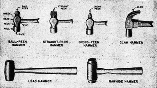
3. Hammers.-The hammer is a very simple striking tool, being just a weighted head and a handle to direct its course. Several types of hammers are shown in Fig. 1.
FIG. 1. TYPES OF HAMMERS.
The ball-peen hammer, often termed the machinist's hammer, is a very useful tool aboard ship. The head of the hammer is made of hardened steel. The handle is of hickory or other hardwood. The flat portion of the head is called the face, and the other end is known as the peen, the latter being used for heading rivets and similar peening or drawing operations. The hole for the handle is the eye. Ball-peen hammers are classed according to the weight of the head without the handle. They vary in size from 4 ounces to 2 pounds, three popular sizes being the 6-ounce for light work, the 12-ounce for general utility, and the 16-ounce for heavy work.
The straight-peen hammer is used for spreading or drawing out metal in line with the handle, while the cross-peen hammer is used for the same operation at right angles with the handle. The claw hammer is used for driving and pulling nails.
Hammers with heads made of soft material, such as lead,
5
copper, babbitt, rawhide, wood, plastic, etc., are called soft hammers. Soft hammers are generally used where a steel hammer might mar or injure the work.
4. The eye in the hammer head is made with a slight taper in both directions from the center. After the handle is inserted in the head, a steel wedge is driven into the end. This expands the taper of the handle in the eye and wedges the handle in both directions. If the wedge starts to come out, it should be driven in again. If the wedge comes out and is lost, it must be replaced before continuing to use the hammer. Never work with a hammer having a loose head. A loose head will eventually fly off, and may injure someone.
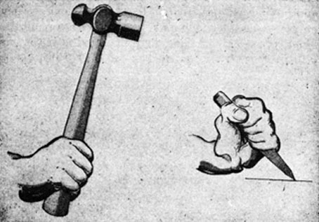
When using a hammer, it should be held near the end of the handle with the face of the hammer parallel to the work. A grip just tight enough to control the blow is best. The correct way to hold a hammer is shown in Fig. 2.
FIG. 2. How TO HOLD A HAMMER.
Keep the hands and the hammer handle free from grease and oil, otherwise the hammer may slip from the grasp. It should also be remembered that oil or grease on the hammer face may cause it to slip off the work and lead to a painful bruise. Do not ruin the hammer handle by using it for pounding or prying purposes.
6
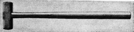
5. Sledges.-Sledges, or sledge hammers, are used for heavy work. They can be procured in both single-face and double-face types, a double-face sledge being shown in Fig. 3, and vary in weight from 4 to 20 pounds. The handles vary in length up to 36 inches.
FIG. 3. SLEDGE.
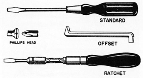
6. Screwdrivers.-Screwdrivers have three main parts: the handle, which is gripped by the user; the shank, which is the steel portion extending from the handle; and the blade, which is the end that fits into the slot of the screw. Several types of screwdrivers are shown in Fig. 4.
Fig. 4. TYPES OF SCREWDRIVERS.
The standard screwdriver is used for most ordinary work and comes in a variety of sizes. The blade must have sharp corners and fit the slot in the screw closely; otherwise it is likely to slip and damage the slot. It is also important that a screwdriver be held firmly against the screw to prevent it from slipping and injuring the worker or the work.
The offset screwdriver makes work possible in tight corners where the straight type will not enter. It has one blade forged in line with the shank, and the other blade at right angles to the shank. With such an arrangement, first one end of the screwdriver
7
can be used and then the other, changing ends after each swing, thus working the screw in or out of the threaded hole.
The Phillips-type screwdriver is made with a specially shaped blade to fit Phillips-type cross-slot screws. The heads of these screws have two slots that cross in the center. This checks the tendency of the screwdriver to slide out of the slot onto the finished surface of the work.
The ratchet screwdriver is used to drive or remove small screws rapidly.
Some screwdrivers have handles made of insulating material, and are useful when electrical work is being done. When a screwdriver with an insulated handle is not available, the handles of other screwdrivers can be insulated by wrapping them with tape.
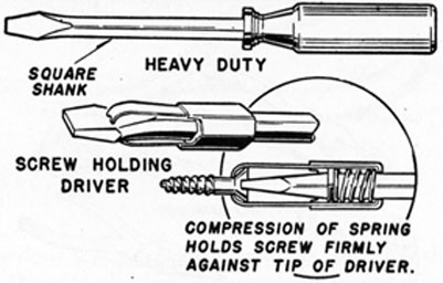
While the screwdriver shown in Fig. 4 has a round shank, some heavy-duty screwdrivers are made with a square shank, the construction enabling the torque of the screwdriver to be increased by applying a wrench to the square shank. A heavy-duty screwdriver, also a special screw-holding screwdriver, are shown in Fig. 5.
FIG. 5. SPECIAL SCREWDRIVERS.
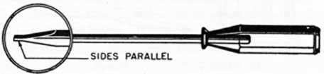
FIG. 6. CORRECTLY GROUND TIP.
7. The tip of a screwdriver blade should be ground so that the sides of the blade are parallel, and the blade sides should
8
gradually taper out to the shank body, as shown in Fig. 6. If the end of the blade is damaged, it can be made serviceable again by means of a grinding wheel. First grind the tip straight and at a right angle to the shank. After the tip is ground square, dress off from each face, a little at a time. Keep the faces parallel for a short distance or have them taper in a slight amount. Never grind the faces so that they taper to a sharp edge at the tip.
Do not use a screwdriver to check an electrical circuit where the amperage is high. The electrical current may be strong enough to form an arc and melt the screwdriver blade. It is also bad practice to try to turn a screwdriver with a pair of pliers or to use it as a chisel.
Do not hold work in the hand while using a screwdriver. If the blade slips, it can cause a bad cut. Hold the work in a vise, secure it with a clamp, or stand it firmly on a solid surface. If such precautions are impossible, take care to have no part of your body in front of the screwdriver blade. That safety rule applies to any sharp or pointed tool.
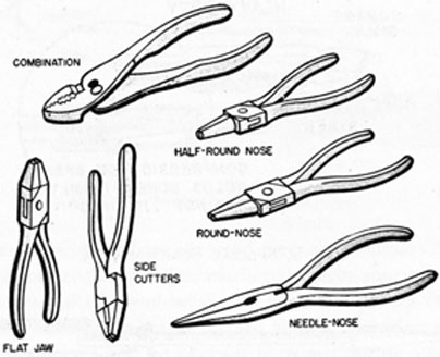
8. Pliers.-Several commonly used types of pliers are shown in Fig. 7.
FIG. 7. TYPES OF PLIERS.
Side-cutting pliers are used principally for holding and bending thin material or for cutting wire. Adjustable combination pliers have a slip joint that permits the jaws to be opened wider at the
9
hinge for gripping large diameters. They are used principally for holding and bending flat or round stock. The various lengths and shapes of flat-nose, round-nose, and needle-nose or long-nose pliers make it possible to bend or form metal into a variety of shapes, to hold objects in tight spots, and to make delicate adjustments. Needle-nose pliers are helpful when recovering a washer or nut from a place where it is hard to reach. They also make it easier to remove and install such things as valve-spring retainer pins. They are not of heavy construction, however, and should not be forced beyond their capacity. Their jaws are comparatively weak, and are easily broken or sprung.
Avoid using pliers on a hardened surface, as such use dulls the teeth and causes pliers to lose their gripping power. Do not use pliers for loosening or tightening nuts, as the flats of the nuts will become damaged.
Diagonal-cutting pliers have short jaws with blades at a slight angle, as shown in Fig. 8. This tool is valuable when removing and replacing cotter pins, and can be used not only to cut the
FIG. 8. DIAGONAL-CUTTING PLIERS.
pins to the desired length but to spread the ends after the pins are in place. They are also handy for cutting the soft wire which is passed through small holes in nuts and bolt heads to "safety" them, or prevent them from working loose. When diagonal-cutting pliers are used, the cut should be made with the throat of the jaws, not with the points, as the latter use would increase the tendency to spring the jaws apart. Once the jaws are sprung, it is difficult to cut fine wire.
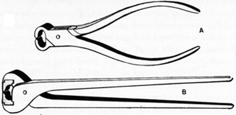
9. Nippers.-Nippers resemble pliers, but are used only for cutting, not for holding. Various types can be used for cutting wire, rod, nails, rivets, and bolts. For light work on soft metals the
10
FIG. 9. NIPPERS.
nippers shown at A, Fig. 9, would be used. They must not be overstrained, however, as their thin cutting edges are easily nicked and dented. For heavier work, the nippers shown at B are used. This type has replaceable blades, a strong joint, and a short fulcrum that provides plenty of leverage. Nippers should not be used to cut such material as drill rod or piano wire.
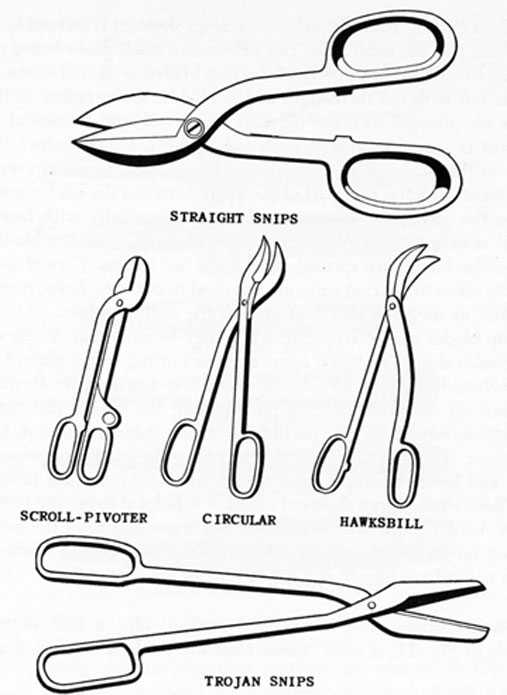
10. Shears and Snips.-Hand shears, or snips, are used for cutting sheet metal of various kinds and thicknesses. Several commonly used types of these tools are shown in Fig. 10.
Straight snips have blades that are flat and straight on the inside surfaces. They are designed for straight cutting but can also be used on large outside curves. It is difficult, however, to cut circles and arcs of small radii with straight snips, the scroll-pivoter snips being more suitable for such purposes. The blades of the latter tool are approximately at right angles and provide clearance for following curves.
Circular snips, with their curved blades, will handle all except the smallest curves. They are available for either right-hand or left-hand use. Hawksbill snips can cut inside and outside circles of small radii. Their narrow curved blades are beveled enough to permit sharp turns without buckling the material. It should be noted, however, that both the circular and hawksbill snips must be used carefully, as their blades are easily sprung out of contact.
Trojan snips are slender-bladed snips used for straight or curved cutting. The blades are small enough to permit sharp turns, and will also cut outside and inside curves. They are sometimes known as combination snips. There are also special snips designed for stainless steel and Monel metal. They resemble Trojan snips, but
11
FIG. 10. SHEARS AND SNIPS.
have inlaid alloy cutting edges. They are identified by the words "For Stainless Steel Only" stamped on them.
11. Snips do not remove any of the metal when making a cut, but work with a shearing action that tends to roughen the edges of the material. Because of this it is better not to cut exactly on the layout line. After the cut is made, the edge can be dressed with a file. There is no set rule for the amount to be allowed for dressing, but the thinner and softer the metal; the closer the cut can be made to the layout line.
12
When cutting from the edge of a large sheet, it is advisable to cut from the left-hand side. This allows the small piece being removed to curl out of the way of the snip blades as the cut is made. Never cut with the full length of the blades. If the points of the snips are allowed to come together, they will tear the metal as the cut is completed. Stop each cut about 1/4 inch before the ends of the blades have been reached, and start a new cut with the throat, which is that part of the angle between the blades nearest to the pivot pin. Cutting in this way, especially with heavy metal, is easier on the snips and is not so likely to spring the blades. When the blades are sprung, hand snips are useless. Care should also be taken to see that snips are not used to cut wire, bolts, rivets, or nails, as such use will dent or nick the cutting edges.
Snip blades can be reground when they become dull. To do so, the blades should be taken apart and the cutting edges ground to an included angle of 85°. Blade tension is adjusted by turning the nut on the pivot bolt, or pin, holding the blades just tight enough to remain in any position in which they are placed. Oil the pivot, spread a thin film of light oil on the blades to prevent rust, and keep the snip blades closed when they are not in use.
When cutting large sheets of metal, it is helpful to lay the metal on the bench and make the cut with the lower handle of the snips resting on the bench top. This lessens the strain on the worker's hand and allows him to use his weight to advantage.
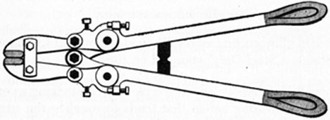
12. Bolt Cutters.-For heavy-duty cutting jobs, a bolt cutter, shown in Fig. 11, is used. These tools are made in several sizes,
FIG 11. BOLT CUTTER.
from 18 to 36 inches in length, the larger ones being used to cut mild steel bolts and rods up to 1/2 inch in diameter. Bolt cutters usually have special replaceable jaws of extra-hard metal alloys;
13
the jaws therefore are brittle and will break before they will bend or dent. Any twisting motion should be avoided when they are used. The tool shown in Fig. 11 has set screws which enable the relative positions of the blades to be adjusted, if they should fail to meet properly after having been sharpened.
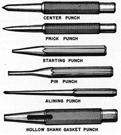
Fig. 12. PUNCHES.
13. Punches.-Several types of punches are shown in Fig. 12. These tools may be used for a variety of jobs, but the correct punch for the job should always be selected.
A center punch is used to make a starting mark for a drill when holes are to be drilled in metal. If the center punch mark is not made, the drill will wander or "walk away" from the desired center. The center punch point should be taper-ground to an angle of about 90°. Never use a center punch to remove a bolt or pin, as the sharp point will act as a wedge and tend to tighten the bolt or pin in the hole.
Prick punches are generally used for marking centers and lines in layout work.
Starting punches, sometimes called drifts, have a long taper
14
from the tip to the body. They are made that way to withstand the shock of heavy blows. They may be used for knocking out rivets after their heads have been cut off, or for freeing pins or bolts from their holes. To start a bolt or pin that is extremely tight, use a starting punch that has a point diameter only slightly smaller than the diameter of the object that is being removed.
After a pin or bolt has been loosened or partially driven out, it may be found that the starting punch is too large to finish the job. A pin punch can then be used, as it is designed to follow through the hole without jamming. Both starting punches and pin punches must have flat ends, never edged or rounded ones.
The alining, or lining up, punch is used to line up corresponding holes in adjacent parts, for example when working on engines that have pans and cover plates.
A special punch, not shown in the illustration, is known as the soft-faced drift. This drift is made of brass or fiber and is used to remove such things as wrist pins. It is heavy enough to resist damage to itself, but soft enough not to injure the finished surfaces of the parts being removed.
When it is necessary to make gaskets of rubber, cork, leather, or composition materials, a gasket punch, one type of which is shown in Fig. 12, is used to cut the bolt holes. This punch comes in sizes to accommodate standard bolts and studs. The cutting end is tapered to a sharp edge so as to produce clean, uniform holes. To use the gasket punch, place the gasket material on a piece of wood that has been cut across the grain, so that the cutting edge of the punch will not become broken or dulled. Then hold the punch against the gasket and strike it with a hammer, driving the punch through the gasket where holes are required.
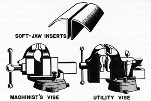
14. Vises.-Two types of vises usually found aboard ship are shown in Fig. 13. The machinist's vise is a heavy-duty holding tool with parallel jaws and either a fixed or swivel base. It should be used only for holding material when hacksawing, filing, drilling, tapping, reaming, etc. It should not be used as an anvil. The utility vise is satisfactory for general work and is designed for a variety of uses. It has a small anvil and anvil horn as part of the back jaw. The anvil surface is broken by a small hole into which the hardie fits. The hardie is the small tool shown in Fig. 13, just above the anvil of the utility vise. It is used for cutting heavy wire and small rods and bars. Pipe jaws, as shown in the illustration, can
15
FIG. 13. VISES.
be mounted inside the regular jaws for holding pipes and rods. Soft jaws, which are inserts of brass, copper, or other soft metal, can be made from scrap metal and mounted on the jaws of a vise when the surface of the work must be protected.
15. For satisfactory operation, keep the vise clean, oiled, and in good general condition. The screw that operates the movable jaw should be lubricated frequently with light grease or heavy cylinder oil. The slide should be wiped clean every day and light machine oil spread over it. Never oil the swivel joint of a vise, however, as its holding power would be impaired. Always tighten and loosen a vise by holding the handle with the hands, applying the weight of the body to secure the turning pressure. Do not hit the vise handle with a hammer. When the vise is not in use, the jaws should be brought lightly together, with the handle in the vertical position.
Be sure to keep fingers clear of the jaws when clamping work in the vise, and use care to keep them from being pinched between the end of the handle and the head of the screw, the latter accident being a very common one. When holding heavy work in a vise, it is advisable to place a block of wood or metal under the work as a prop to prevent it from sliding down and perhaps falling to the floor or on the foot. Care should also be exercised to see that the vise is not opened beyond the limit of the screw,
16
as the movable jaw may drop off and the user suffer serious injury. If it is necessary to pound against metal parts held in a vise, be sure to pound against the back jaw, as it is heavier than the front jaw and strong enough to absorb the shock of the blows.
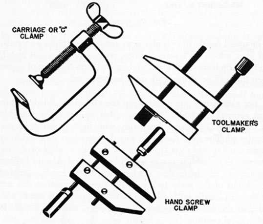
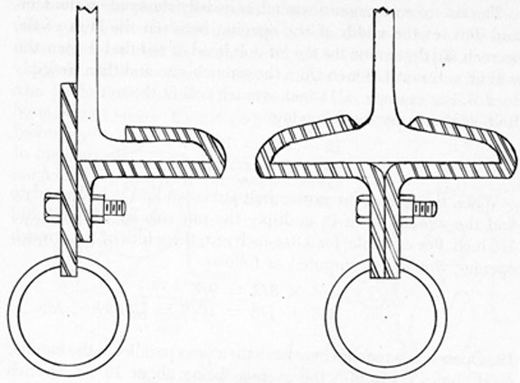
16. Clamps.-When a vise is not available, a clamp can be used to hold pieces of material together while they are being worked on. Clamps of this type are shown in Fig. 14. A different kind of clamp is often used to make a temporary fastening in the engine room when it is desired to lift or take a strain on some object. To do so, the clamp is securely fastened to a convenient beam, as shown in Fig. 15, and a line or small hoist then suspended from the clamp.
FIG. 14. SCREW CLAMPS.
17. Wrenches.-Fundamentally, the wrench is a tool for exerting a twisting strain, as in turning bolts and nuts. As the majority of nuts and bolt heads are hexagonal, or 6-sided, many wrenches are specially designed to fit hex-heads and hex-nuts.
18. Open-end Wrenches.-Solid, nonadjustable wrenches with
17
FIG. 15. BEAM CLAMPS.
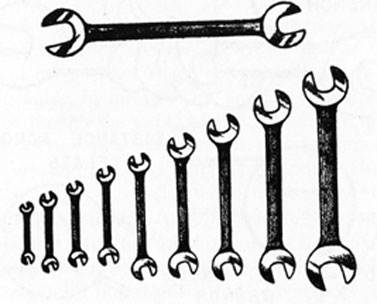
openings in one or both ends are called open-end wrenches. A set of these tools is shown in Fig. 16. Open-end wrenches with small openings are usually shorter than wrenches with large openings, thus proportioning the lever advantage of the wrench to the size of the work and helping to prevent breakage of the wrench or damage to the bolt or stud.
FIG. 16. SET OF OPEN-END WRENCHES.
18
The size of an open-end wrench is usually stamped on the face, and denotes the width of the opening between the jaws of the wrench. To determine the size of bolt head or nut that the wrench will fit, subtract 1/8 inch from the wrench size and then multiply by 2/3. For example, a 1 5/8-inch wrench will fit the nut of a 1-inch bolt, as shown by the following.
1 5/8 - 1/8 = 1 1/2
1 1/2 X 2/3 = 1 inch. Ans.
When the size of the nut or bolt is known and it is desired to find the wrench to fit it, multiply the nut size by 3/2 and add 1/8 inch. For example, for a 3/4-inch nut, the width of the wrench opening would be computed as follows:
3/4 X 3/2 = 9/8
9/8 + 1/8 = 10/8 = 1 1/4 inches. Ans.
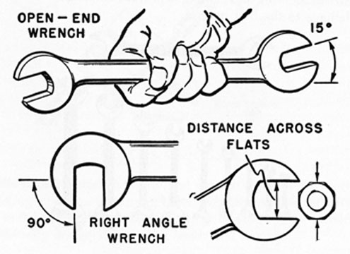
19. Open-end wrenches may have their jaws parallel to the handle, or at angles up to 90°, the average being about 15°. A wrench with 15° angles and a wrench with a 90° angle are shown in Fig. 17.
The jaws of open-end wrenches are placed at an angle in order to make it easier to work with the wrenches in close quarters, as it is frequently necessary to tighten or loosen a nut where there is very little space in which to swing a wrench. The procedure
FIG 17. OPEN-END WRENCHES.
19
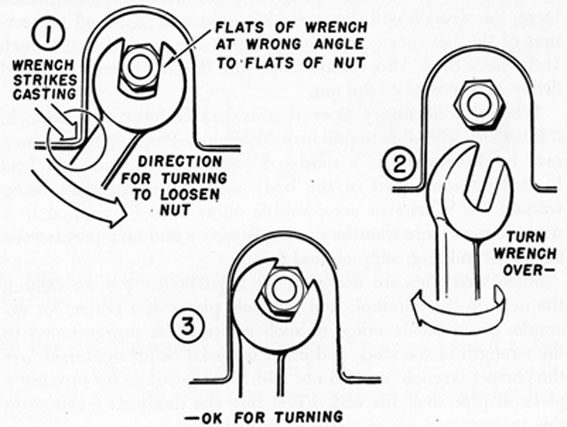
known as flopping the wrench is therefore used, that is, turning the wrench over so that the other face is down after each stroke. In a situation such as shown in Fig. 18, view (1), it is not possible to place the jaws of the wrench on the nut when held in the position illustrated. However, with the wrench turned over, as shown in views (2) and (3), it is possible to apply the wrench
FIG. 18. USE OF OPEN-END WRENCH.
to the nut and turn it in the direction for loosening. Although not shown in the illustration, the wrench will have to be turned over at the end of each swing. When a wrench has jaws at the 15° angle, it is possible, by means of the flopping technique, to turn a hex-nut even though the swing of the wrench is limited to 30°.
There are special open-end wrenches, such as tappet wrenches, which are very thin and have extra long handles. They are used to adjust the valves of small internal combustion engines, and must be handled with care. A set of ignition wrenches is used in caring for engine electrical systems.
Aboard ship, heavy-duty open-end wrenches are often needed in order to handle large nuts. These are known as drive-up wrenches. In some cases one man will hold the wrench on the nut, keeping a firm pulling strain on it, while another person
20
strikes the wrench with a sledge hammer. Some wrenches are so large that a pulling strain is taken with a chain fall, and the wrench is then struck by a heavy ram supported by a block and tackle and wielded by several men.
20. When selecting an open-end wrench, be sure that the wrench jaws fit the nut or bolt head. If the wrench opening is too large, the wrench will slip around the nut and round off the corners of the hex-faces, possibly springing the jaws of the wrench at the same time. Also, always make sure that the wrench is seated firmly on the flats of the nut.
When it is necessary to exert considerable force on a wrench, it is usually advisable to pull instead of push. Pushing on a wrench may be dangerous, as a sudden loosening of the nut can lead to striking some part of the body against the machine being worked on. Whenever considerable effort is to be applied to a wrench, make sure that the footing is secure and take precautions against stumbling, slipping and falling.
Some wrenches are designed for a particular job, to tighten the nuts on the handhole and manhole plates of a boiler, for example. Since the leverage of such a wrench is proportioned to the strength of the studs and other material being tightened, use the correct wrench, and do not add to its leverage by slipping a piece of pipe over the end. Exceeding the designed leverage in this manner can cause stripped threads and broken studs, nuts and other parts, and lead to the breakdown of a piece of machinery and injury to personnel.
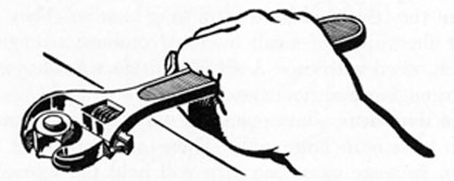
21. Adjustable Wrenches.-A handy all-round wrench for light work is the adjustable open-end wrench, such as shown in Fig. 19. One jaw of this wrench is fixed; the other jaw is moved along a slide by a screw adjustment, the angle between the jaw opening
FIG. 19. ADJUSTABLE OPEN-END WRENCH.
21
and the handle being 22 1/2°. An adjustable wrench will not stand the hard usage of an open-end wrench and must be used very carefully. It is important that its jaws be closely adjusted to fit the nut, and it should always be used so that the force of the pull comes on the solid, or stationary, jaw, as shown in Fig. 19.
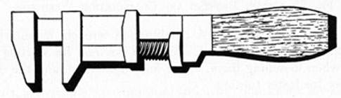
Monkey wrenches, one of which is shown in Fig. 20, are useful in many instances, when tightening or loosening pipe unions, for example, or where the exact size of open-end wrench is not available. When using monkey wrenches, take the same precautions
FIG. 20. MONKEY WRENCH.
as with adjustable wrenches. Always have the jaws point in the direction of the pull.
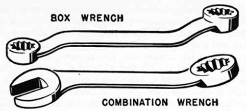
22. Box-end Wrenches.-Some box-end wrenches have 6 inside
faces, or notches, but most of them have 12 notches, as shown in
Fig. 21, this wrench being known as a 12-point or double-hex box
wrench.
FIG. 21. BOX-END WRENCH.
There is little chance for a box-end wrench to slip off the nut, and it cannot spread on the nut and cause undue wear. Because the sides of the box opening are comparatively thin, the wrench is suitable for turning nuts that are hard to reach with an open-end wrench. An offset box-end wrench is shown in Fig. 22.
When using box-end wrenches, and there is insufficient room to turn the wrench in a complete circle, it is necessary to lift it off the nut after each pull and then place it back on in another position. In this case, therefore, after a tight nut is started, it can often be unscrewed much more quickly with an open-end wrench
22
FIG. 22. OFFSET BOX-END AND COMBINATION WRENCHES.
than with a box wrench. A combination wrench, as shown in Fig. 22, is therefore helpful, using the box end for starting the nuts when loosening them, or for final tightening, and the open end for faster turning.
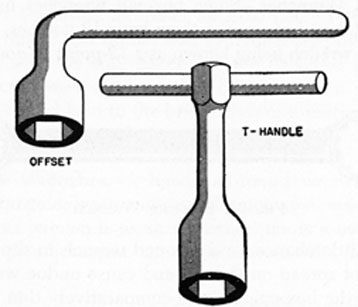
23. Socket Wrenches.-Two typical one-piece socket wrenches are shown in Fig. 23. These are heavy-duty wrenches, made with 4 inside faces for square nuts or with 6 inside faces for hex-nuts. This type of socket wrench, however, does not have the wide
FIG. 23. ONE-PIECE SOCKET WRENCHES.
adaptability of detachable socket wrenches, a set of which contains an assortment of individual sockets of various sizes made to fit different handles. There are several types of handles, such as the T-handle, ratchet handle, screwdriver-grip handle, and speed handle, the latter resembling a carpenter's brace. A ratchet
23
FIG. 24. SOCKET WRENCHES.
handle, a T-handle, an extension, and a 12-point socket are shown in Fig. 24.
To use a detachable socket wrench, select a socket that fits the nut, place the socket on the projecting lug of the handle and then place the socket over the nut. The socket is held on the lug by a small friction catch that engages when the socket and lug are forced together.
The ratchet handle permits the wrench to be turned without removing it from the nut, a gear shift often being incorporated in the construction so that the nut can be turned in either direction without turning the wrench over.
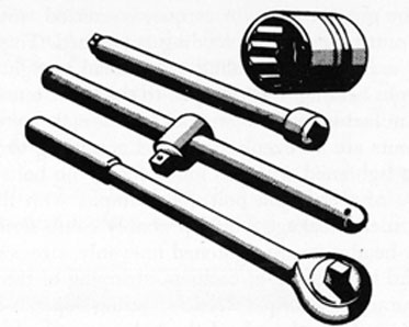
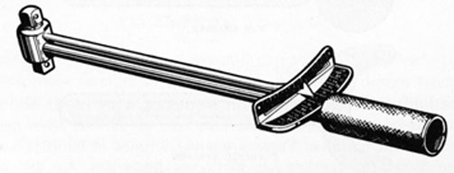
24. Torque Wrench.-One type of torque wrench is shown in Fig. 25. This tool is used as a socket wrench handle in order to exert the desired amount of strain when tightening nuts and bolts. As the torque wrench is pulled, the scale or dial of the tool
FIG. 25. TORQUE WRENCH.
24
indicates how great a twist, or torque, is exerted, and the pull is continued until the desired reading is reached. This is very important in many cases, enabling a workman to tighten the bolts of a crankpin bearing, for example, to the exact tension specified by the manufacturer of the engine, and to make sure that cylinder-head nuts are all evenly tightened according to instructions. If nuts are tightened with too much force, the bolts may break. In the case of a crankpin bolt, for example, with the engine in operation, such breakage would probably cause serious damage. If cylinder-head nuts are tightened unevenly, stresses may be set up that lead to cracking of castings, stripping of threads, etc.
The accuracy of a torque wrench reading depends in part upon the condition of the threads of the bolt or nut and on the lubrication of the threads. Readings are more accurate when the threads are in good condition and well lubricated.
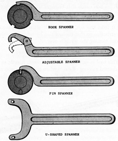
25. Spanner Wrenches.-Several types of spanner wrenches are shown in Fig. 26. The hook spanner works on a round nut which has a series of notches cut in its outer surface. The hook, or lug,
FIG. 26. SPANNER WRENCHES.
25
is placed in one of the notches and the handle turned to loosen or tighten the nut. An adjustable spanner is designed to fit nuts of various diameters. Pin spanners have a pin instead of a lug, the pin fitting a round hole in the edge of the nut. U-shaped spanners have either lugs or pins that fit in notches or holes in the top of the nut or screw plug.
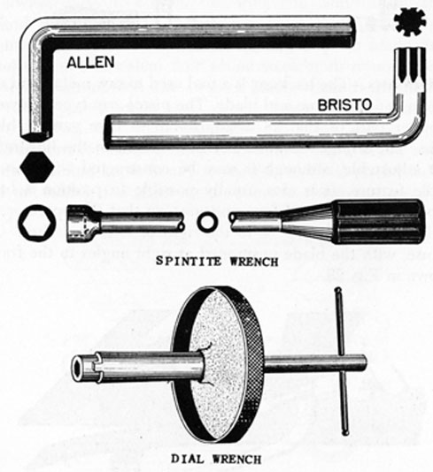
26. Special Wrenches.-Several special wrenches are shown in Fig.
27. The Allen-type wrench has a 6-sided shaft that fits into the
FIG. 27. SPECIAL WRENCHES.
hex-shaped recess of set screws and cap screws. The Bristo-type wrench has a number of splines on the shaft, the design tending to reduce spreading. The Spintite wrench has a hollow shaft with a hex- head, and is used for electrical work. It should therefore have an insulated handle. The dial-wrench is a special wrench for removing and replacing the dials of electrical and computing equipment.
26
FIG. 28. HACKSAWS.
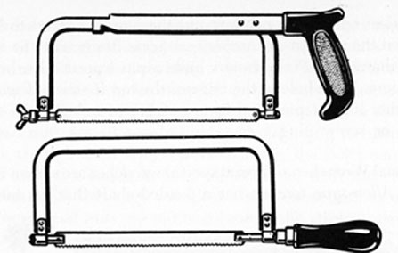
27. Hacksaws.-The hacksaw is a tool used to saw metal, and consists of a handle, frame and blade. The pistol-grip type, shown in the upper part of Fig. 28 is adjustable to take various blade lengths. The straight-handled hacksaw shown in the illustration is not adjustable, although it may be constructed with the adjustable feature. It is also usually possible to position a hacksaw blade in any one of four positions, so that the operator can saw downward, upward, or to the right or left, as desired. One such use, with the blade positioned at right angles to the frame, is shown in Fig. 29.
FIG. 29. BLADE AT RIGHT ANGLES TO FRAME.
Hacksaw blades have holes in both ends and are mounted on the frame by means of pins attached to the frame. The blade must always be mounted in the frame with the teeth pointing away from the handle, and should be tightened with enough tension to hold it rigidly between the pins.
27
Blades are made of high-grade tool steel or tungsten steel, and are available from 6 to 16 inches in length. There are two types, the all-hard blade and the flexible blade. In the flexible blade, only the teeth are hardened. The pitch of a blade indicates the number of teeth it has per inch, pitches of 14, 18, 24 and 32 being available.
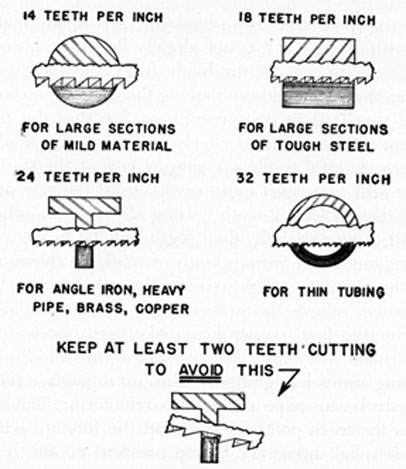
28. When selecting the best blade for a job, it is necessary to consider the type of blade and the pitch. An all-hard blade is best for sawing brass, tool steel, cast iron, and heavy cross-section stock. A flexible blade is usually best for sawing hollow shapes and metals having a light cross section. A 14-pitch blade should be used on machine steel, cold-rolled steel, or structural steel, as it will cut fast and free. The 18-pitch blade, which is the blade for general purpose work, is used on solid stock of aluminum, bearing metal, tool steel, high-speed steel, cast iron, etc. A 24-pitch blade is used for cutting thick-wall tubing, pipe, brass, copper, and channel and angle iron. Use the fine tooth 32-pitch blade for thin-wall tubing and sheet metal. Some of these uses are shown in Fig. 30.
FIG. 30. USE THE CORRECT BLADE.
28
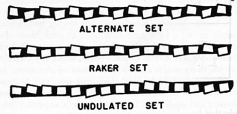
When selecting a blade, it is also necessary to consider the set, which means that some teeth are pushed sideways in one direction and the same number in the opposite direction, according to definite patterns. The set provides clearance for the blade so that it will not jam and stick, and also prevents overheating the blade. Since the blade has a thickness of about .025 inch, the set causes it to make a cut about twice that wide. Three types of set are shown in Fig. 31.
Fig. 31. TYPES OF SET.
29. When preparing to use a hacksaw, secure the material in a vise, or with clamps, if it is not already firmly anchored. It must be held firmly to prevent the blade from chattering or twisting. Make sure that the hacksaw blade is the correct one for the purpose and that it is in good condition. See that the teeth point away from the handle, and check and adjust the blade tension.
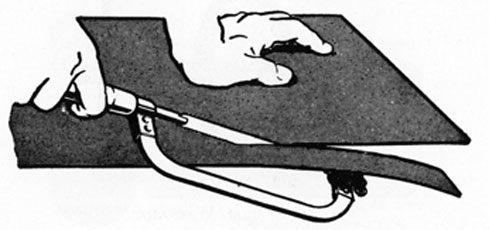
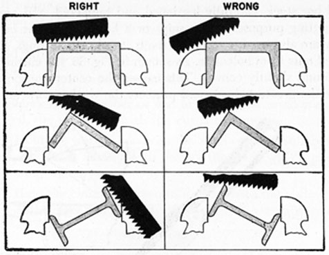
It is often helpful to file a V-shaped nick at the starting point; the blade will then start more easily. Hold the saw at an angle that will keep at least 2 teeth cutting all the time, otherwise the blade will jump and individual teeth will be broken. The right and wrong angles for various kinds of work are shown in Fig. 32.
Start the cut with a light, steady, forward stroke. At the end of the stroke, relieve the pressure and draw the blade straight back. After the first few strokes, make each one as long as the hacksaw frame will allow, thus preventing the middle teeth from overheating and wearing rapidly. Use just enough pressure on the forward stroke to make each tooth remove a small amount of metal. As the teeth point forward and the forward edges do the cutting, it is not necessary to use pressure on the back stroke.
When sawing alongside a scribed line, remember to stay just
29
FIG. 32. STARTING HACKSAW CUTS.
outside that line. Use long steady strokes, about 40 to 50 strokes per minute. If hacksaw blades are worked too fast, the heat that is generated may draw the temper and make the- blade soft and useless. Working too fast also may break some of the teeth, cramp and break the blade, or produce ragged and crooked cuts. When near the end of the cut, slow down still more, so that the saw can be controlled when the stock is sawed through. When finished with the saw, clean the chips from the blade, loosen the tension, and return the hacksaw to its proper place. A hacksaw should be hung up when not in use. It should not be kept in a drawer with other tools or where metallic objects will strike the blade teeth. Wiping the blade with an oily rag will prevent rusting.
When a saw blade is broken and a new blade is to be used, turn the work so that the cut can be resumed on the other side, if possible. The reason is that the set of the new blade is greater than that of the used saw, and the new blade would possibly jam if work were continued at the same place. If it is necessary to use the new blade exactly in the same cut, however, run it through the unfinished part very carefully before attempting to complete the job.
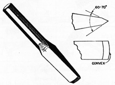
30. Chisels.-One of the most valuable tools aboard ship is the flat cold chisel. These chisels are usually made of octagonal
30
tool-steel bar stock, carefully hardened and tempered, and are used for cutting purposes where snips or a hacksaw cannot be used. They are also used to shear off rivets, to smooth castings, to split rusted nuts from bolts, etc. As shown in Fig. 33, the cutting edge is ground slightly convex. This causes the center portion to receive the greatest shock, and protects the weaker corners.
FIG 33. FLAT COLD CHISEL.
Chisels must be sharp to give satisfactory service. The cutting angle should be about 60°, as shown in Fig. 33, and sharpening is best done on a wet grinding wheel. However, if a dry wheel is used, the chisel should not be pressed too hard against the wheel, or held there for too long a time. Too much pressure or lengthy periods of grinding will generate sufficient heat to draw the temper out of the steel. A container of water should be kept at the grinder and the chisel dipped in it after each light cut. This cools the metal and enables the grinding to be continued. Remember that the chisel will not be safe to use if the cutting angle is ground too small. On the other hand, if the angle is much over 60°, the tool will not cut properly.
31. When using a chisel for ordinary work, a hammer weighing from 1 to 1 3/4 pounds should be used. However, be sure to use a hammer that is heavy enough for the job. When using a larger chisel, a heavier hammer must be used. Hold the chisel in the hand with the head of the chisel close to the thumb and first finger, and grasp it firmly, but with the fingers rather relaxed. When the chisel is gripped in this manner, the user will not be
31
hurt so badly if he should miss the chisel and strike his hand with the hammer. Do not look at the head of the chisel while striking it with the hammer; watch the cutting edge.
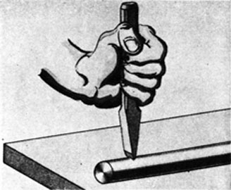
When cutting wire or round stock with a cold chisel, the following procedure is recommended:
(a) Mark with a scriber or file, or with chalk or colored pencil, the point at which the cut is to be made.
(b) Hold the work in place on the anvil or other suitable support. (It is advisable to protect the anvil with a piece of scrap metal.)
(c) Hold the chisel as shown in Fig. 34, with the cutting edge on the mark and the body of the chisel in a vertical position.
FIG. 34. CUTTING ROUND STOCK WITH COLD CHISEL.
(d) Strike the chisel a light blow with the hammer, and then examine the chisel mark on the work to make certain that the cut is at the desired point.
(e) Drive the chisel into the work with vigorous blows. The last few strokes, however, should be made lightly in order to avoid unnecessary damage to the supporting surface.
(f) Heavier work can be cut in much the same way, except that the cut is made about halfway through the stock from one side, then the work turned over and the cut finished from the opposite side.
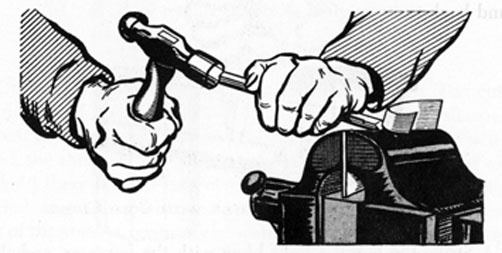
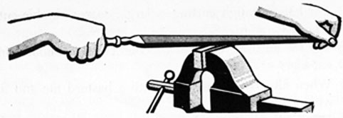
32. The cutting of sheet or plate metal with a cold chisel should be avoided whenever possible, as stretching of the metal
32
invariably results. However, when no other means are available, the best procedure is as follows:
(a) With a scriber, draw a straight line on the work where the cut is to be made.
(b) Grip the work firmly in a vise with the scribed line even with or just below the top of the vise jaws, as shown in Fig. 35. The waste metal should extend above the jaws. In some cases it is better to place the metal between two pieces of angle iron and clamp the whole set-up in the vise. The angle iron then protects the tops of the vise jaws.
(c) Using a sharp chisel, start at the edge of the work and cut along the scribed line, using the vise jaws (or the pieces of angle iron) as a base for securing a shearing action. Hold the chisel firmly against the work and strike it vigorously. Be sure to keep the cutting edge of the chisel flat against the vise jaws.
FIG. 35. CUTTING SHEET METAL WITH COLD CHISEL.
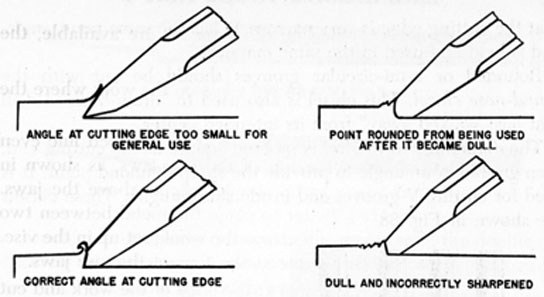
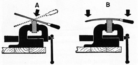
33. Chipping is the term applied to the method of removing metal from a surface with a chisel, as shown in Fig. 36, which also illustrates the correct and incorrect methods of preparing the cutting edges. When chipping steel, it is advisable to lubricate the chisel point with light machine oil. This makes the chisel easier to drive and helps it to cut faster than when dry. When chipping cast iron, chip from the edges of the work toward the center to avoid breaking off corners.
34. After a chisel has been used for some time, the blows of the hammer will cause the head to spread out until it looks like a
33
FIG. 36. CORRECT AND INCORRECT SHARPENING.
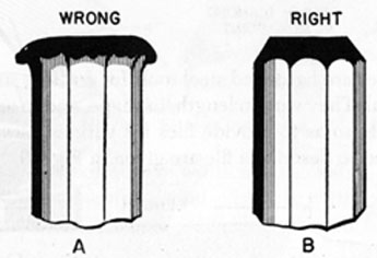
ragged mushroom. The spread-out head is rough, and will cut the hand very easily. In some cases, pieces of the jagged edge may break away and fly off with sufficient force to injure someone working nearby. The head of the chisel must therefore be periodically ground back to its original shape, as shown in B, Fig. 37.
FIG. 37. KEEP CHISEL HEAD GROUND OFF.
Always wear goggles when chipping with a chisel. Also be careful not to send chips flying toward other workmen or into machinery. The safest method is to have a guard (a piece of canvas of sufficient size attached to two wooden pedestals) placed so as to catch the flying chips. Keep the hammer and the head end of the chisel clean and free of grease and oil to prevent the hammer from slipping.
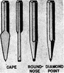
35. Special Cold Chisels.-If it is necessary to cut keyways or slots, the cape chisel can be used. This chisel is like a flat chisel except
34
that the cutting edge is very narrow. It has the same point angle, and is held and used in the same manner.
Rounded or semi-circular grooves should be cut with the round-nose chisel. This chisel is also used to "draw back" a drill that has "walked away" from its intended center.
The diamond-point chisel is tapered square at the cutting end, then ground at an angle to provide the sharp diamond point. It is used for cutting V-grooves and inside sharp angles. These chisels are shown in Fig. 38.
FIG. 38. SPECIAL CHISELS.
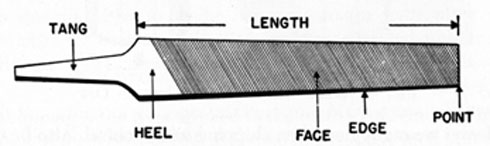
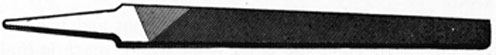
36. Files.-Files are hardened steel tools for cutting, smoothing, or polishing metal. They vary in length, in shape, and in arrangement, or cut, of teeth, so as to provide files for various uses. The terms commonly used to describe a file are given in Fig. 39.
FIG. 39. FILE TERMINOLOGY.
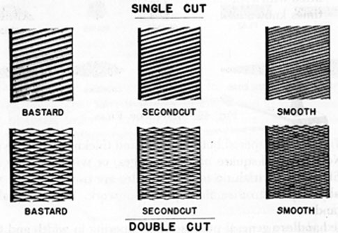
37. Files have either single-cut or double-cut teeth. The difference between the two types of teeth is apparent when comparing Figs. 40 and 41. Single-cut files have rows of teeth cut parallel to each other, the teeth being set at an angle of about 65° with the centerline. Single-cut files are used for sharpening. tools, finish filing, and draw-filing. They are also the best tools for smoothing the edges of sheet metal.
35
FIG. 40. SINGLE-CUT FILE.
FIG. 41. DOUBLE-CUT FILE.
Double-cut files have criss-crossed rows of teeth, the double cut forming teeth that are diamond-shaped and suitable for quick removal of metal and for rough work.
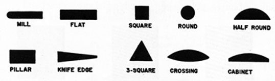
38. In selecting a file for a job, it is necessary to consider its shape, which means both the outline and the cross-sectional shape. Some of the cross-sectional shapes of files are shown in Fig. 42.
FIG. 42. SHAPES OF FILES.
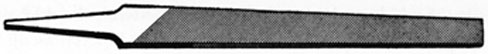
Mill files are tapered both in width and thickness, and are available with either square or round edges, or with one safe edge, that is, an edge with no teeth. Mill files are used for lathe work, draw-filing, and other fine, precision work. They are always single-cut.
Flat files are general purpose files, tapering in width and thickness, and generally used when a fast cutting tool is desired. Hand files, not shown, are somewhat thicker than flat files, but their edges are parallel.
Square files are tapered on all four sides and are used to enlarge rectangular-shaped holes and slots. Round files serve the same purpose for round openings. Small round files are often called rat-tail files.
The half-round file is a general purpose tool, the rounded side being used on curved surfaces and the flat face on flat surfaces. When filing an inside curve, a round or half-round file with a
36
curve most nearly matching the curve of the work should be used.
Triangular, or 3-square or 3-corner files, are tapered on all three sides. They are used to file cutters, acute internal angles, and to clear out square corners. Special triangular files are used to file saw teeth.
A warding file, not shown, is extremely thin and has sharply tapered edges. Its chief use is on work where space is limited. Knife files have one thin edge and one thick edge, and are used on keyways, slots, etc. A rasp is similar to the file except that it has coarse teeth raised by a triangular punch, and is usually used on wood.
39. Files are also graded according to the spacing and size of their teeth, or their coarseness and fineness. These grades are known as rough-cut, middle-cut, bastard, second-cut, smooth and dead-smooth. Three grades of teeth are shown in Fig. 43. The fineness or
FIG. 43. GRADES OF FILE TEETH.
coarseness of file teeth is also influenced by the length of the file. If the teeth of a 6-inch, single-cut smooth file, for example, are compared with those of a 12-inch, single-cut smooth file, the difference will be noted.
40. The type of material to be filed, and whether it is a rough or finishing cut, determine the grade of fineness that is required. Various typical situations may be listed as follows:
37
(a) For heavy, rough cutting, a large, coarse, double-cut file is best.
(b) For the finishing cut, use a second-cut or a smooth single-cut file.
(c) When filing cast iron, start with a bastard file and finish with a second-cut.
(d) When filing soft steel, start with a second-cut file and finish with a smooth file.
(e) When filing hard steel, start with a smooth file and finish with a dead-smooth file.
(f) When filing brass or bronze, start with a bastard file and finish with a second-cut or smooth file.
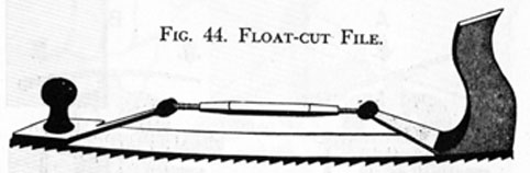
(g) When filing aluminum, lead, or babbitt metal, use a bastard file, or if available, a float-cut file may be used. This file has large curved teeth and works with a planing action. It is fitted with a special holder, as shown in Fig. 44, and is sometimes known as a vixen-cut file.
FIG. 44. FLOAT-CUT FILE.
41. Never use a file unless it is equipped with a tight-fitting handle. If a file is used without the handle and it strikes something accidentally or jams to a sudden stop, the tang may be driven into the hand.
File handles are made of wood with a ferrule, or metal strengthening ring, on the end, and a hole to receive the tang of the file. The usual way of driving the handle on the file is to insert the end of the tang into the hole in the handle, and then tap the end of the handle on the bench or some other flat surface. If the tang of the file is considerably larger than the hole in the handle, the hole may be enlarged by burning it out with the heated tang of a file. A piece of wet rag or waste should be wrapped about the file up to the tang before the file is heated, to prevent its temper from being drawn.
The correct way to hold a file is with the handle against the palm
38
FIG. 45. CORRECT WAY TO HOLD FILE.
of the right hand, thumb on top, as shown in Fig. 45. Hold the end of the file in the left hand with the fingers curled under it. When filing, lean the body forward during part of the forward stroke and straighten up at the finish. The file must be held straight or the surface of the work will not be flat. Not more than 30 or 40 strokes per minute should be taken; too much speed will cause the file to rock, and the corners of the stock will be rounded off, as indicated in view A of Fig. 46. Too much pressure will bend the file and tend to have the effect shown in view B.
FIG. 46. TOO MUCH SPEED AND TOO MUCH PRESSURE.
Apply pressure on the forward stroke only. Unless the file is lifted from the work on the return stroke, it will become dull much sooner than it should. (This does not apply, however, when filing very soft metals, such as lead or aluminum. On soft work, pressure on the return stroke helps to keep the cuts in the file free of removed metal.)
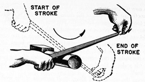
42. When round surfaces are filed, best results are obtained by working as shown in Fig. 47, a rocking motion being used.
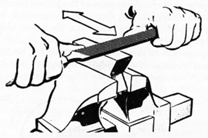
Surfaces and edges are often draw-filed to make them smooth and true. In draw-filing, hold the file at right angles to the work,
39
FIG. 47. FILING ROUND SURFACES.
FIG. 48. DRAW-FILING.
as shown in Fig. 48, and move the file sidewise along the work. A single-cut smooth file should be used. Pressure is heaviest on the stroke made toward the body and very light on the return. Keep the hands as close together as possible to prevent bending the file, and watch the ends and corners of the work, as they are easily rounded. For a smoother surface than can be obtained by draw-filing, wrap a piece of fine emery cloth around the file and proceed as in draw-filing.
When filing work that is rotating in a lathe, long, slow cuts give best results. The work must be rotating at high speed. For rough work, a double-cut flat file is generally used. For finishing work, a mill file gives better results, as it is a single-cut file and has a shearing action. Too much filing of a piece of work in a lathe, however, will, as a rule, spoil it by making it out of round.
40
43. A new file should be broken in by using it first on brass, bronze, or smooth cast iron. Most of the damage to new files is caused by using too much pressure during the first few strokes, so it is necessary to use a light pressure to prevent tooth breakage. A new file should not be broken in on a narrow surface, such as the edge of sheet metal, because the narrow edge is likely to break off the sharp points of the teeth. A new file should never be used to remove the scale on cast iron; always use old, worn files for removing such scale. A file should never be used on material harder than itself.
During the operation of filing, small particles of the work are likely to clog the teeth of the file and scratch the material being filed. This condition is known as pinning. Pinning is sometimes the result of putting too much pressure on the file, especially if it is a new one. To avoid pinning, therefore, be sure that the file is broken in properly. Rubbing chalk on a file before using it will also help to prevent pinning.
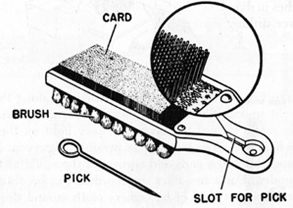
Pinning can also be prevented by cleaning the file frequently. This is done by means of a file card, an example of which is shown in Fig. 49. When cleaning a file, lay it flat on the bench and draw
FIG. 49. FILE CARD.
the bristles of the file card back and forth across the file parallel to the cuts. If a few chips are stubborn and will not come out, remove them with the pick that is included with the file card.
To prevent scratching or cutting too deep when filing wrought iron, steel, or hard fiber, apply a little oil to the surface of the file.
41
However, do not use oil when filing cast iron, as it causes the cast iron surface to glaze over and become hard and slick.
44. A file is easily dulled by rough or improper handling, and files therefore should not be stored in a drawer or box where they can rub against each other or against other tools. It is best to store them, in separate holders, or in holes cut in a wooden block. Do not use a file for prying or pounding. The tang is soft and bends easily, the body is hard and extremely brittle, and even a slight bend may cause a file to snap in two. Bending or pounding a file, therefore, will not only injure the file but may cause steel particles to be thrown into the eyes. For similar reasons a small rat-tail file should not be salvaged to be used as a prick punch or center punch.
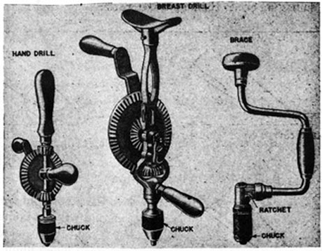
45. Drills and Drilling.-There are many occasions when it is necessary to drill holes in metal, using a twist drill, a tool that does its work by slicing metal away as it rotates. With holes up to 1/4 inch in diameter, the drilling may be done by hand, using a hand drill or breast drill to hold and turn the drills. A brace is ordinarily used when drilling holes in wood. These hand drilling tools are shown in Fig. 50.
Twist drills are also used for cutting larger holes in metal, up to 4 inches in diameter, but for such purposes are usually operated by power drilling equipment.
FIG. 50. HAND DRILLING TOOLS.
42
Twist drills are made of carbon steel or high-speed alloy steel. Carbon steel drills are satisfactory for the general run of work and are less expensive, although they may lose their hardness if heated excessively. High-speed drills are used on tough metals and at high speeds. They will keep on cutting when red hot, but should be cooled in still air; if cooled quickly they may crack or split.
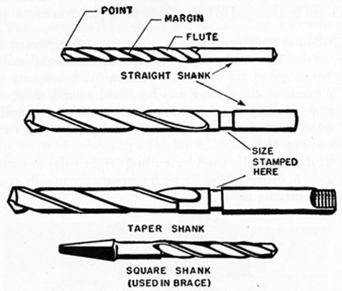
The drill shank is the end that fits into the chuck of the hand drill, electric drill or drill press. Straight-shank drills are used to drill holes up to about 1/2 inch in diameter. Larger holes are usually drilled with the taper-shank drill. The square-shank drill is made to use in a brace. The different shanks are shown in Fig. 51.
FIG. 51. TWIST DRILL SHANKS.
Twist drills are available with either 2, 3, or 4 flutes (the spiral grooves formed along the sides), but drills having 3 or 4 flutes are used for following smaller drills or for enlarging cored holes, and are not suitable for drilling into solid stock. The spiral flutes provide several advantages:
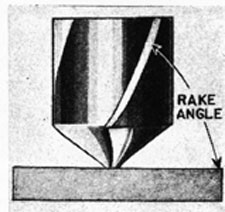
(a) They give a correct rake angle to the lips, as shown in Fig. 52.
(b) They cause chips formed while drilling to curl tightly so that they occupy the minimum amount of space.
43
(c) They form channels through which such chips can escape from the hole.
(d) They allow the lubricant, when one is used, to flow easily down to the cutting edge of the drill.
FIG. 52. RAKE ANGLE.
46. Drill Sizes.-The twist drills used most frequently are those made in fractional sizes, from 1/64 inch up to 1 inch in diameter, although larger sizes are also found aboard ship. The size of the drill is stamped on the shank. Because the drills vary 1/64 (0.0156) inch from one size to the next, two other identification systems have been developed for special sizes:
(a) Number drills, ranging from No. 80 (0.0135 in.) to No. 1 (0.228 in.).
(b) Letter drills, ranging from A (0.234 in.) to Z (0.413 in.).
Tables of drill sizes will be found in Marine Engineering Tables, issued later in the course.
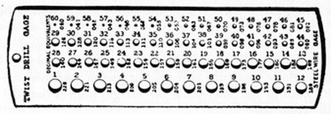
If the size number has worn off the drill shank, the size can be checked with a drill gage, Fig. 53, for the number drills, with a drill stand for fractional drills, or with a micrometer for any kind of drill. When measuring a drill with a micrometer, measure from
FIG. 53. DRILL GAGE.
44
the outside of one margin to the outside of the other margin (see Fig. 54) at the point of the drill. The shank diameter of a straight-shank drill is usually a few ten-thousandths of an inch smaller than the point diameter.
47. Use of Lubricant.-When drilling, some materials require no lubricant while others require a lubricant peculiar to their nature. The following tabulation may be used as a guide:
Materials to be Drilled
Lubricant
Tool steel, copper
Oil
Soft steel, wrought iron
Oil or soda water
Babbitt, brass, cast iron
No lubricant (dry)
Glass
Turpentine
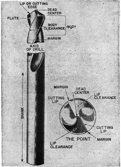
48. Drill Terminology.-Before a drill is used on any kind of work, it is important that it be correctly ground and sharpened. If a drill is not in proper condition for work, it will drill with difficulty, make a hole that is rough or off size, and perhaps break while in use. It is important, therefore, to become familiar with the various parts of the drill, as identified in Fig. 54, so that the work of grinding and sharpening can be carried out most efficiently.
The dead center is the sharp chisel edge at the extreme tip end of the drill. It is formed by the intersection of the cone-shaped surfaces of the point and should always be in the exact center of the axis of the drill.
The point of a drill is the entire cone-shaped surface at the cutting end. It should not be confused with the dead center.
The heel of a drill is the portion of the point back of the cutting lips or edges.
The lip clearance angle is the angle at which the drill point is ground off just back of the lips.
The margin is the narrow strip which extends the whole length of the flutes, being part of a cylinder that is interrupted by the flutes and by what is known as body clearance.
The portion of the drill back of the margin is of slightly less diameter than the margin, and the difference is known as body clearance. Body clearance reduces the friction between the drill mid the walls of the hole, while the margin insures that the hole is of the right size.
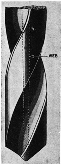
The web is the metal column, Fig. 55, which separates the flutes.
45
FIG. 54. TWIST DRILL TERMINOLOGY.
It runs the entire length of the drill between the flutes, gradually increasing in thickness toward the shank.
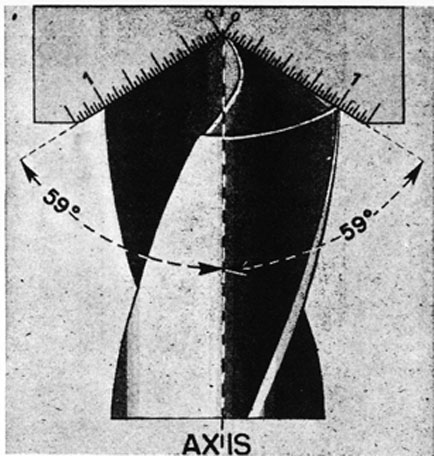
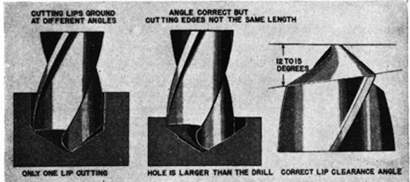
49. Drill Lips.-It has been determined that for work on mild steel and for general purpose work, the lips of a twist drill should be ground to a 59° angle, or with an included angle of 118°, as shown in Fig. 56. In this illustration the angle is measured by a drill gage. (Note that both lips are exactly the same length.) If the angle is too great, the point will be too flat to center properly; if the angle is too small, the hole will be drilled less rapidly than it should be, and more power will be required to drive the drill. If the point is on center but the cutting edges are ground at different angles,
46
Fig. 55. DRILL WEB.
the drill will bind on one side, as shown in the left-hand view of Fig. 57, and as only one lip will do the work, that edge will wear rapidly. When the cutting edges are not the same length, the hole will be larger than the drill, as shown in the center view.
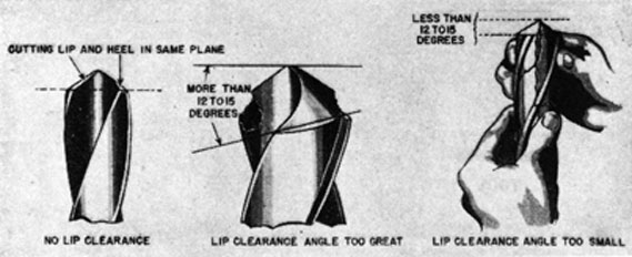
50. Lip Clearance Angle.-For most drilling, the heel of the drill should be ground away from the cutting lips at an angle of from 12° to 15° at the circumference of the drill, as shown in the right-hand view, Fig. 57. This angle is known as the lip clearance angle. Examples of incorrect lip clearance grinding are shown in Fig. 58.
The drill at the left, Fig. 58, has been ground without any lip clearance whatever; in the center example, the lip clearance angle is so large that the cutting edges of the drill have broken down because of insufficient support; in the illustration on the right, the lip clearance angle is too small.
47
FIG. 56. CORRECTLY GROUND DRILL.
FIG. 57. EXAMPLES OF LIP GRINDING.
51. Rake Angle.-The rake angle of a drill is the angle of the flutes in relation to the work, as shown in Fig. 52. It is usually between 22° and 30°. If the rake angle is too small, it makes the cutting edge so thin that it may break under the strain of the work. The rake angle also partly governs the tightness with which the chips curl, and hence the amount of space they occupy.
48
FIG. 58. EXAMPLES OF INCORRECT LIP CLEARANCE GRINDING.
52. Recommended Angles for Various Materials.-The following tabulation states the lip angles and lip clearance angles that are recommended for common materials:
Materials to be drilled
Drill Angles
Heat-treated steels, drop forgings, Brinel hardness No. 250.
125° included angle 12° lip clearance
Cast iron, soft
90° included angle 12° lip clearance
Brass
118° included angle 12° lip clearance Slightly flat face of cutting lips
Copper
100° included angle 12° lip clearance
Wood
60° included angle 12° lip clearance
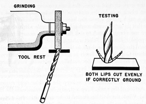
53. Grinding a Drill.-After the instructions have been studied carefully, considerable practice is still needed in order to learn how to grind a drill correctly. To secure this practical experience, it is advisable to begin by selecting a correctly ground drill; a 1/4-inch or 3/8-inch size would be suitable for the purpose. Take the drill to the grinder, and without turning on the grinder, observe just how the drill must be held in order to secure the correct shape of the point and the desired angles. The way in which the drill is held against the grinding wheel is shown in Fig. 59.
49
FIG. 59. GRINDING A DRILL.
Next take a drill that needs grinding badly, and start up the grinder and try to shape the point of the old drill to be exactly like the correctly ground drill. Remove very little metal at first and examine the drill frequently in order to note the progress made. Also take the same precautions that are explained in Art. 30 in connection with the sharpening of chisels. By working and observing carefully it will soon become apparent how the drill must be held in order to secure the desired results. Check the lip angle and lip clearance angle, and when the drill appears to be ground properly, try drilling a hole in a piece of soft steel scrap. Note whether the drill cuts smoothly and rapidly, or whether it jumps and chatters. Do the chips curl away evenly from both lips? Is the hole the right size? Examine the heel of the drill; if there are shiny spots, it is indicated that the lip clearance angle is too small. If the drill will not cut at all, it is probably because there is no lip clearance. Be careful to keep both lips the same length, and have the included angle as previously recommended.
Always protect drills from nicks and rust. See that they are ground properly before putting them away, and then store them carefully.
54. Drilling.-When drilling with a twist drill, the following procedure is recommended:
(a) Locate the exact position of the hole by drawing two lines
50
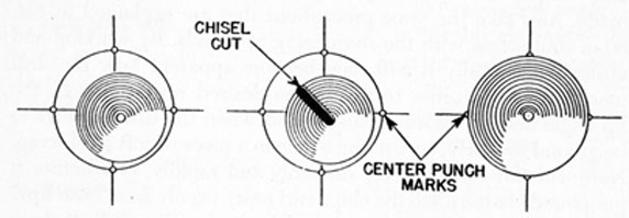
on the work at right angles, the lines crossing each other at the point which is to be the center of the hole. Make a light mark with a prick punch where the lines intersect, and check to make sure that the prick punch mark is located exactly where they cross. Then use a center punch to sink the mark deep enough to receive the point of the drill. Select a sharp, properly ground drill of the desired size; insert the shank in the chuck and fasten it tightly in position. Grip the work firmly in a vise unless it is stationary. Arrange to do the drilling horizontally, if possible. Put a drop of lubricant, if needed, in the impression made by the center punch. Place the point of the drill in the center punch impression and begin drilling, making sure to keep the drill at right angles to the surface of the work. Keep a steady, firm pressure on the drill.
(b) When the drill has started to cut and has made an impression larger than the center punch mark, lift it from the work and note whether the impression is concentric with the cross lines. If it is not concentric, as shown in the left-hand view, Fig. 60, use a round-nose chisel to make a nick in the impression on the side of the center toward which the drill should be drawn. The chisel cut is shown in the center view, Fig. 60.
FIG. 60. HOW TO DRILL BACK TO CORRECT CENTER.
(c) Put another drop of lubricant in the impression and continue drilling until the point of the drill just breaks through the metal. Then ease off on the pressure and drill slowly until the hole is completed. If the drill catches while finishing the hole, work the drill back and forth carefully until it cuts through the work. When the hole is completed, withdraw the drill immediately by pulling it back as it continues to turn.
55. Portable Power Drills.-A portable electric drill is used in much the same way as a hand drill. The chuck shaft, or arbor, is
51
geared to the motor to obtain the desired speed. Small drills are geared up for high speed, but the larger drills are geared down so that the chuck will turn slowly enough to prevent damage to the drill from burning. Portable power drills can also be used for such operations as buffing, polishing, and grinding.
With the addition of a special attachment which converts the rotary motion of the drill into a reciprocating motion, a portable power drill can be used for making holes in concrete and similar materials. The same attachment can also be employed to adapt the machine for lighting riveting work.
Except for the smallest units, the extension cable of portable electric drills should include a ground lead from the drill casing, and a clip for connection of the ground lead to ground. The clip should be fastened to a grounded conductor, such as the conduit at the outlet box, before the drill is placed in operation. This precaution protects the operator of the drill from electrical shock in case the insulation of the wiring within the power drill casing should fail, resulting in a short circuit.
Portable electric drills are susceptible to short circuits because of their small clearances and the metallic dust produced when they are used. These conditions can be improved by periodically blowing through the motors with clean dry air. Since dampness is another reason that may cause the machines to deteriorate, they should always be stored in a dry place when not in actual use. It is also advisable that they be regularly tested for insulation resistance.
Before a portable power drill is used, the extension cable should be inspected carefully to -make sure that it is not frayed or crimped to such an extent that wiring is exposed. Care should also be taken that the cable does not drop or lie in water. The operator of the drill should wear leather gloves and keep his footgear dry, especially where dampness may be present.
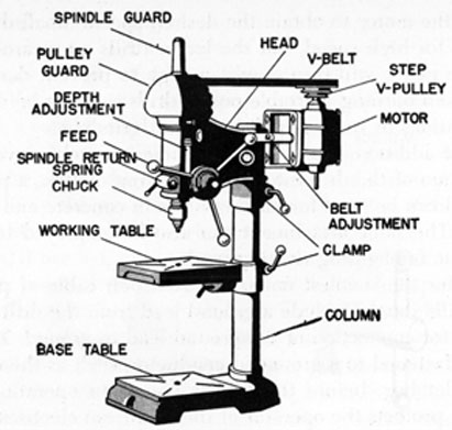
56. Drill Press.-A small drill press, such as might be used aboard ship, is shown in Fig. 61. This drill press has a separate motor which drives the drill spindle and chuck by means of a V-belt.
One advantage of the drill press over the portable electric drill is that speed control is provided. Four steps are usually found on the motor pulley and four on the spindle pulley. The drill press in the illustration is arranged for high speed, with the belt on the largest step of the motor pulley.
52
FIG. 61. DRILL PRESS.
The feed pressure is easily controlled on this drill press by means of a feed wheel with long handles. A depth stop is provided to stop the progress of a drill at a predetermined depth, which is important when drilling holes that do not go all of the way through the material.
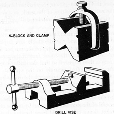
When using a drill press, it is very important to hold the drilled material securely. Never try to hold it down by means of the hands, as the drill may catch or jam and spin the material around at high speed, endangering everyone within range. The best method is to use a drill vise or some other form of clamping device. A drill vise, also a V-block and clamp used to hold round objects, are shown in Fig. 62. Use the drill vise for small jobs, and clamp larger pieces of stock to the drill table.
It is usually advisable to protect the drill table by placing a block of wood beneath the work, thus preventing the drill from touching and scarring the drill table as it completes the drilling of a hole.
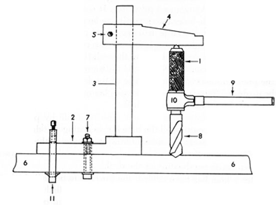
57. Heavy-duty Ratchet Drill.-When the hole to be drilled is too large for an electric drill, and the piece to be drilled cannot be taken to a drill press, a heavy-duty ratchet drill can be used. In order to use the drill, some arrangement must be made to apply
53
FIG. 62. DRILL VISE AND V-BLOCK.
1. ratchet sleeve
2. base
3. upright
4. adjustable arm
5. bolt
6. steel plate
pressure upon it. The arrangement may utilize blocking, depending upon the nature and position of the work, or a device known as an "old man" may be used. A ratchet drill set up in an "old man" is shown in Fig. 63.
As shown in the illustration, the base of the device is bolted or clamped in position, and the adjustable arm is placed at the proper height so that the pointed tip of the ratchet fits into one of the countersunk holes in the lower face of the arm. The position of the arm is then adjusted so that the drill is lined up properly, and the arm is bolted securely on the upright. By turning the ratchet sleeve so as to screw it upward, the drill is held securely between the arm and the work, and drilling can be begun. The drill is turned by pulling on the ratchet handle. In order to feed the drill into the work, a rod is placed in one of the small holes at the upper end of the ratchet sleeve, and by means of this leverage the ratchet sleeve can be held from turning during part of the stroke of the ratchet handle, thus lengthening the drill assembly and feeding the drill through the work. The amount of feed given is determined by the nature of the work being done, and can be judged by the amount of pull needed to move the ratchet handle.
58. Pilot Holes.-A small hole, used to guide and mark the path for a larger drill, is known as a pilot hole. It is a good policy to drill these small guide holes for any drill size larger than 3/16-inch, as it is difficult to start a large drill in a center punch mark, the large drill having a tendency to drift from the center. The pilot hole guides the larger drill all the way through the metal and helps to keep it "on the course." No special drills are required, just select the pilot drill according to the size of the finished hole that is to be made, a 1/8-inch drill, for example, being satisfactory for drilling a pilot hole for a 3/8-inch drill.
59. Keep a drill cutting all the time it is in contact with the metal. Apply pressure steadily and uniformly to insure continuous cutting. Remember that both too much pressure and too little pressure can cause overheating of the drill.
After a hole has been drilled, the burrs must be removed. An easy way to remove them is to use a drill about twice the diameter of the hole. Hold the drill in the hand and rotate the point against the burrs. Do not burr a hole too much, however, as the hole should
55
be a true cylinder and should not be countersunk at either end unless so specified.
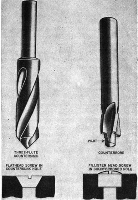
60. Countersinks.-A countersink is used to shape the ends of drilled holes to fit screw, bolt, and rivet heads of the countersunk type. The 3-flute 82° countersink is usually used, although other point angles are available for special purposes. Countersinks are made in a number of sizes, but any one size can be used on several different sizes of hole.
61. Counterbores.-A counterbore is used to cut recesses in metal
surfaces for fillister-head bolts and screws, and for similar purposes, working best when used in a drill press or lathe. The pilot end of the tool is smooth, and is guided by the hole drilled for the bolt or screw. A countersink and a counterbore are shown in Fig. 64.
62. Solder.-Solder is used to join pieces of metal, to make metal joints and seams leakproof, and to connect electric wires so that they will be good conductors.
Soft solder is used most often in sheet metal and electrical work, and is usually a combination of 50 per cent tin and 50 per cent lead, known as half-and-half solder. Solder is manufactured in both bar and wire forms, some wire solders having hollow centers which are filled with acid or rosin core fluxes.
Half-and-half solder begins to melt at a temperature of 358°F, and becomes a liquid at 415°F. It does not have much strength, and should never be used where heavy stresses will be applied to the soldered parts. Solders containing 55 per cent to 70 per cent tin are stronger and can withstand heavier stresses than half-and-half solder, but no soft solder approaches the strength of the hard solders.
Hard solders are made of alloys of copper, zinc, silver, and tin. They will withstand considerable stress, pressure and vibration, and may be used to solder high-pressure pipe connections, gasoline and oil piping joints, etc. The hard solders must be melted with a blowtorch or welding torch; soldering irons do not conduct enough heat to melt them.
63. Soldering Irons.-Soldering irons, or coppers, are available in
various weights, but the size used should depend on the
56
FIG. 64. COUNTERSINK AND COUNTERBORE.
requirements of the work to be done. As a general rule it is best to select the largest size that is convenient to handle.
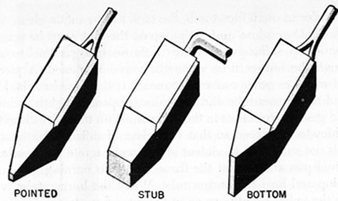
The points of soldering irons should be rather blunt for efficient heat conduction, three different shapes being shown in Fig. 65. The pointed shape is used for utility work; the stub shape is used for flat seams that require considerable heat; and the bottom type is best for soldering the seams of pans, trays, etc. An electric soldering iron, with interchangeable tips, can be used for light work and is especially good for work on electrical connections.
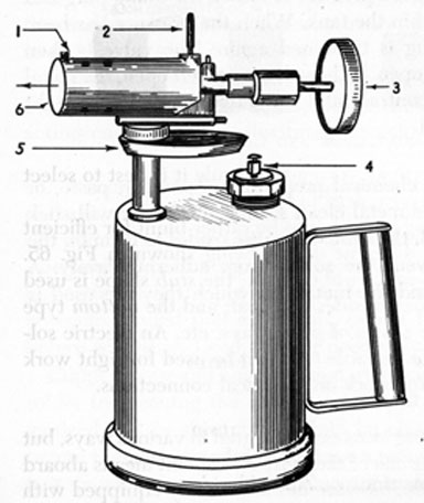
64. Blowtorch.-Soldering irons can be heated in various ways, but the gasoline blowtorch is one of the most convenient means aboard ship. As shown in Fig. 66, blowtorches are usually equipped with
57
FIG. 65. SOLDERING IRON POINTS.
a hook and curved rest to hold the soldering iron while the point is exposed to the flame of the torch.
Before using a blowtorch it is advisable to consider the danger of fire. Do not light or use the torch near openings where explosive gases may be present, where gasoline has been spilled, or where inflammable material may be ignited. It is good practice to have a fire extinguisher handy whenever a blowtorch is used.
In order to use a blowtorch, the tank must contain clean, white (unleaded) gasoline, and the pump on the tank must be operated to build up sufficient pressure to cause the gasoline to spray through the burner tube when the valve is opened. A piece of sheet metal or other convenient means is then used to shield the end of the burner tube and the valve is opened slightly, allowing liquid gasoline to collect in the fuel pan. With the valve closed and the blowtorch placed so that it is clear of inflammable material and is not subjected to violent air currents, ignite the gasoline in the fuel pan and permit the flame from the burning gasoline to envelop and heat the burner tube. When the burner tube is hot, open the valve slightly, so as to permit a fine stream of gasoline to be discharged from the tank. The gasoline should vaporize immediately and burn with an almost colorless, light-blue flame. Be sure to open the valve wide enough to permit satisfactory operation. When the torch is burning satisfactorily, the valve can be opened or closed slightly in order to adjust the flame to the desired intensity. A blue flame indicates good combustion conditions. While the torch is in use it is necessary to work the pump a few strokes periodically in order to maintain pressure in the tank.
To extinguish a blowtorch, close the valve. After the torch has been extinguished, it is good practice to loosen the filling plug and relieve the pressure within the tank. When the pressure has been relieved, the filling plug is tightened again. The valve is then opened slightly and left open. If the valve is not left open, the metal around the valve will contract and the valve may stick so tight that it will be damaged.
65. Fluxes.-A flux is a chemical preparation (powder, paste, or liquid) used to keep the metal clean so that the solder will stick to it. If a flux is not used, the heat will cause oxides to form on the metal surface and prevent the solder from adhering firmly. A list of common fluxes and the metals on which they are used is given in the following:
Metals
Fluxes
Brass, copper, tin
Rosin
Lead
Tallow, rosin
Iron, steel
Borax, sal-ammoniac
Galvanized iron, zinc
Zinc chloride
59
Fluxes are either corrosive or non-corrosive. The commonly used corrosive fluxes; zinc chloride and sal-ammoniac, corrode the metal if allowed to remain on it after soldering. They should therefore be completely removed by a thorough washing after the work is done. 'It is for this reason that rosin, a non-corrosive flux, is used when soldering electrical connections. The rosin is used in powdered form, or as a liquid core in wire solder.
Zinc chloride can be prepared by dissolving small pieces of zinc in commercial hydrochloric acid, commonly known as muriatic acid. The zinc should be added a little at a time until the bubbles stop rising, and a little undissolved zinc remains in the solution. It is important to note that the gas released when these bubbles reach the surface is hydrogen, which is highly explosive. It is therefore advisable to practice the same precautions as with storage batteries, that is, keep the room well ventilated and avoid the use of open flames.
The solution should be strained and then diluted to the correct strength by pouring it into an equal amount of water. (Always pour the acid into the water; it is dangerous to pour water into acid.) The resultant liquid is zinc chloride, also known as "cut-acid" or "killed acid." It is recommended that a few small pieces of zinc be placed in the liquid in order to neutralize any free acid that may remain. As acid fluxes eat away metal, they must be stored in pottery or glass containers.
Paste fluxes, commercially manufactured, are available in cans of various sizes. These fluxes, which contain grease for counteracting corrosion, are substitutes for acid fluxes.
66. Tinning.-Tinning means to spread a thin layer of solder on the surfaces of the metals that are to be soldered together, causing the solder to adhere to the metal and make a firm union with it. The purpose of tinning is to prepare the surfaces so that they will unite readily in the process of soldering and make a firm joint. It is recommended that all metals, except lead and tin, be tinned before soldering. Lead and tin need only to be scraped clean.
Copper, brass and ungalvanized iron may be prepared to receive solder by cleaning the surfaces and applying zinc chloride. Galvanized iron or sheet zinc should be cleaned with muriatic acid before the solder is applied. Where a metal has become tarnished, it is necessary to remove the tarnish and expose the bare, clean
60
metal before tinning it; otherwise the solder ordinarily will not adhere to the metal.
67. Tinning the Soldering Iron.-The point of a soldering iron must be tinned before it will do a good job of soldering, tinning in this instance referring to the process of coating the point with solder to prevent oxidation when heated. The general steps in the tinning procedure are as follows:
1. File the faces of the point (or rub them with emery cloth) until they are smooth and flat.
2. Heat the point hot enough to melt the solder readily, but do not heat it red hot.
3. Rub the faces of the point on a sal-ammoniac brick, applying a small amount of solder to the point as it is rubbed on the sal-ammoniac. The solder will form a thin bright film on the faces of the point.
4. If a sal-ammoniac brick is not available, the point can be tinned by rubbing it in pulverized rosin and solder.
When a soldering iron is overheated, the tinning is destroyed. If this happens, the point should be allowed to cool, and then should be filed and retinned.
68. Dipping Solution.-When a soldering iron is heated, the scales that tend to form on the point can be removed by dipping the point in a dipping solution, which is made of one part of sal-ammoniac powder mixed with 40 parts of water. Only the tip of the point should be dipped in the solution and it should be withdrawn quickly. The tinned point will emerge bright and clean.
A soldering iron should never be dipped into zinc chloride or other acid solution, as the acid may spatter into the eyes or on the skin and clothing, and possibly cause blindness or severe burns.
69. Soldering Procedure.-Ordinary soldering is done by heating the material to a temperature that will melt the solder, and then applying the solder to it. The procedure that will help to secure strong, neat soldering is as follows:
1. Clean the surfaces to be soldered. Solder will not stick to dirt or grease. Do not depend on the heat and flux to remove all of it.
61
2. Use a well-tinned soldering iron. In some cases it is advisable to have two of them, heating one while soldering with the other.
3. Use the proper flux.
4. Control the heat. Do not allow the soldering irons to overheat, but have them hot enough to melt solder readily.
5. Keep the soldered surfaces close together to insure a strong bond.
6. Do not handle or move a soldered job until the solder has "set" and has partially cooled. Solder is weak and brittle during the process of solidification.
The ideal way to apply solder is to flow it on. To preheat the surfaces so that the solder will flow on, the point should be held as shown in Fig. 67. When the surfaces are hot enough, the point is moved slowly along the seam. Note that the solder is added to the seam, and that the point is held in such a manner that it heats the metal in advance of the flowing solder. Keep one face of the point flat against the work so that the heat will be conducted rapidly to the metal.
FIG. 67. APPLYING SOLDER.
It is often easier to solder sheet metal if the seam is "tacked" first. This is done by applying small drops of solder at intervals along the seam, as shown in Fig. 67, one drop at a time being picked up and applied with the tip of the soldering iron.
Sweat soldering is used when the contacting surfaces of two pieces of metal are to be soldered together. First the surfaces are tinned and then they are placed together and a soldering iron or blowtorch used to heat them and "sweat" them together. Pipe fittings, lugs, and electrical terminals are soldered in this manner.
70. Electric Wire Splicing.-The proper methods of splicing
62
electric wires should be clearly understood, as breakdowns have been traced to faulty splicing with its resulting loose connections and opening of circuits. Loose connections also cause increased electrical resistance and may lead to a fire because of the sparking or heating that is likely to occur at such faulty joints.
The requirements of a good splice are:
1. That it be both mechanically and electrically secure without solder.
2. That it be soldered well and neatly to prevent corrosion.
Wire used for lighting and power purposes has a rubber covering which is usually protected on the outside with cotton braid. The wire itself is made of copper and is often tinned to prevent corrosion. In order to make a splice with this wire, a pair of pliers and a good sharp pocketknife are necessary. The knife is used for stripping the insulation from the wire, the sharp edge of the knife blade being used for cutting the insulation and the back of the blade for scraping, so as to prevent dulling of the cutting edge.
Insulation should not be cut away as shown in (1), Fig. 68, because this kind of cut is liable to nick the wire. A wire can be easily broken if it is nicked, and the cross section of the wire is also reduced at the nicked point, thereby increasing the resistance to flow of current.
The correct way to cut the insulation is to whittle it off in a manner similar to sharpening a pencil, as shown in view (2), Fig. 68. When the rubber and braid have been removed for a sufficient distance, the remaining rubber is then scraped off until the metal shines. Do not scrape off the tinning, however.
To make a tap splice, strip about 4 inches of insulation off the end of the wire to be connected, and strip about 1 1/2 inches of insulation off the running wire. Hold the wires firmly and make one turn with the connecting wire on the running wire. Then pass the end of the connecting wire beneath itself, as shown in view (4), Fig. 68, and make about 6 turns around the running wire, in the opposite direction. A tap splice, correctly made, is shown in view (4); an improper splice is shown in view (3).
A fixture splice is largely used in wiring fixtures or in places where it is necessary to connect wires of different sizes. First, strip the insulation off each of the two wires for a distance of 5 inches and then scrape the wires clean. Hold the wires firmly, as shown in view (5A). Then twist the wires together with the pliers,
63
FIG. 68. ELECTRIC WIRE SPLICES.
64
making three complete turns, as shown in (5B). Make sure that both wires twist. If only one wire twists and the other remains straight, the joint will not hold and it will be loose. Cut both ends to the same length and bend the twisted portion close to the long wire, as shown in (5C). Straighten out the two ends, as shown in (5D), and then wrap the ends around the long wire in the same direction as the twist. The completed splice is shown in (5E).
The Western Union splice is the most common splice used in connecting wires. Strip off about 5 inches of the insulation and scrape as explained previously. Hold the wires firmly in position, as shown in (6A). Then make 5 or 6 turns with one wire, as in (6B), and the same number of turns in the other direction with the other wire, as in (6C). Cut the ends of the wires off short and pinch the ends down with pliers so as to be sure that no sharp points remain to stick out and cut through the insulating tape that is applied after the joint is soldered. Make sure that the turns are tight and close together and that there is no movement when the splice is finished, (6D).
In view (7), a Western Union splice is shown as it would be used in a twin conductor. The important point to note here is that the splices are placed so that they cannot touch each other.
71. Soldering Electrical Splices.-The following procedure should be carried out when preparing electric wires for soldering and in soldering the connection:
1. Heat the soldering iron.
2. Clean the wires to be soldered, removing insulation and scraping the surface of the wires, as explained previously, until they are bright and clean.
3. If the wires are not previously tinned, place a thin film of flux on them. (Rosin is recommended for electrical connections.) Do not use an excess of flux, however.
4. Test the soldering iron for temperature by touching the tip to the solder. If the iron has to be held on the solder in order to melt it, the iron is not hot enough. However, if the solder melts at once, the iron is ready for use.
5. Tin the soldering iron, as previously explained.
6. With the iron hot and tinned, tin each wire by bringing the
65
iron in contact with the wire, at the same time touching the point of contact with the solder.
7. Splice the two wires together, as explained previously. Then apply a thin film of flux and bring the soldering iron in contact with the solder and the splice, as shown in Fig. 69. When sufficient solder is melted on the splice, remove the solder and iron. Hold the connection securely until the solder hardens.
Fig. 69. SOLDERING AN ELECTRICAL SPLICE.
If the temperature of the material being soldered is not brought up to the melting point of the solder, the result will be a "cold soldered" connection. Such a joint might give the appearance of proper bonding, but the electrical continuity of the circuit would be poor, and the poorly soldered connection would offer high resistance to a flow of electric current.
After electrical splices are soldered they should be carefully taped in order to avoid short circuits. The splice should first be covered with rubber tape, and then friction tape should be wound over the rubber tape.
72. Terminals.-When an electrical conductor is to be sweated into a terminal, it is advisable to select a terminal lug that will take all of the strands snugly in its shank, and which at the same time has the same external diameter as the braid on the conductor, for this gives a neat finished appearance. Use a knife to cut away all of
66
the braid and rubber insulation for a distance equal to the depth of the hole in the lug, as shown in Fig. 70. With the point of the knife, clean out every bit of rubber that remains in the spaces between the outer layer of strands, and then spread all of the strands out so that they can be cleaned thoroughly for tinning. However, do not spread them enough to bend them much out of their original position, as it is necessary to pack them in as close as possible when sweating them into the terminal. It is also advisable to cut away
FIG. 70. SWEATING CONDUCTOR IN TERMINAL LUG.
the outer braid around the rubber insulation for about 3/8 inch in order to avoid burning. If the braid should catch fire while the solder is being applied, it might burn sufficiently to require an extra amount of tape and result in a poor appearance.
A blowtorch is used on this type of job, and the flame of the torch is played freely on the copper strands, solder and flux being applied until the entire exposed length is thoroughly tinned and all of the wires are bonded together. While still hot, wipe the surface with a rag so that the end of the conductor will slip into the lug. If the lug is not already tinned on the inside, clean it with emery cloth and hold it with a pair of pliers in the blowtorch flame, applying solder and flux until the hole is full of molten solder. Place the end of the conductor in the flame again in order to bring it up to the same temperature as the solder in the lug, and then insert
67
the conductor in the lug, taking care to keep the hands clear of the overflowing hot solder. Let the flame play on the terminal and lug for a few seconds in order that the molten solder and strands of wire will mix thoroughly, and then remove from the flame and cool with a water-soaked rag or piece of waste. The shank of the lug should be cleaned with emery paper, and rubber tape and friction tape applied as shown in Fig. 70. A coating of black insulating varnish should then be added.
73. Direct Flame Soldering.-As explained in the preceding article, some soldering work can be done more easily with a direct flame than with a soldering iron. A blowtorch can be used on larger jobs, but in other cases an alcohol torch is more useful.
FIG. 71. ALCOHOL TORCH.
An automatic alcohol torch, shown in Fig. 71, is a self-contained unit, with two separate compartments. One compartment contains a supply of alcohol for the wick, the other contains the alcohol for the jet of flame. When the wick is lighted, the heat from its flame heats the jet tube, which causes the alcohol to vaporize and build up a pressure. The pressure forces some of the alcohol vapor out through the small jet opening, where it is ignited to form a hot, light blue flame. When the flame is passed over an electrical splice, for example, and rosin core solder applied, the joint can be soldered very efficiently.
Another type of automatic soldering iron, suitable only for use with alternating current, has two electrodes, a built-in transformer, and a pistol grip. By pressing on the grip, a trigger switch is closed, current is passed through the electrodes, which are shaped for convenient application to the joint, and almost instantaneous soldering is achieved.
74. Safety Precautions.-Fuel used in blowtorches or similar equipment presents a dangerous fire hazard, so it must be used and
68
stored with the greatest care. Do not fill a blowtorch or an alcohol torch near an open flame or where a spark might ignite it. Do not attempt to solder a can or tank that has contained gasoline, alcohol, etc., unless it is first thoroughly steamed for several hours. Be sure to disconnect an electric soldering iron when through using it. Be careful where a hot soldering iron is placed; it may start a fire or burn yourself or a shipmate.
75. Welding.-The term fusion welding is often encountered in marine engineering texts, and means that the parts to be welded are melted together, sometimes with the addition of extra metal. Welders often do this work with electric arc welding equipment or with oxyacetylene gas torches.
Electric arc welding is used on the joints of large pipe lines, for repairing iron and steel castings, and for welding other structures and plates. An arc welding set-up is shown schematically in Fig. 72.
Most arc welding is done with metal electrode filler rods, which are coated with flux suitable to the material being welded. The electrode is held in a spring-jaw holder which is connected by a heavy insulated cable to the generator or other power source. To
FIG. 72. ARC WELDING SET-UP.
69
provide a return for the arc current, another cable, called the ground, connects the metal being welded to the power source. The ground cable has a clamp-type terminal for easy attachment and removal.
The end of the metal electrode and nearby portions of the metal being welded are melted by the heat of the arc, and they are thus fused together. The electrode supplies the extra metal that is usually required to make a strong weld.
The arc of arc-welding equipment has a temperature of about 5,000°F, and a few minutes exposure to the ultra-violet rays of the arc will produce a "sunburn." To protect the face and eyes, arc welders wear a heavy face mask with a dark glass window. They also wear leather jackets and aprons to protect their bodies from the heat.
Oxyacetylene welding, or gas welding, is done with a welding torch, which mixes the acetylene and oxygen gases to provide fuel for the flame. Two heavy hoses are connected to the torch, one leading to the acetylene supply, the other to the oxygen supply. Portable gas welding units have high-pressure steel containers of the gases, often mounted' on a two-wheel cart, as shown in Fig. 73.
FIG. 73. PORTABLE OXYACETYLENE WELDING UNIT.
70
Regulating valves control the pressure released from the steel flasks to the hose lines, while hand valves on the torch regulate the amount of each gas that is released inside the torch and also control the mixture.
Additional metal necessary for gas welds is obtained from a welding rod, the rods being selected by diameter and by the kind of material suitable to the welding job. Fluxes are used as required.
An oxyacetylene flame is capable of producing a maximum temperature of about 6,300°F, the size of the flame being regulated by the torch valves and by the size of the tip used on the torch.
An explanation of the symbols and other terms used in fusion welding will be found in Marine Engineering Tables.
76. Brazing.-Brazing, a process by which two metal parts are united by the addition of molten metal, but without fusion of the parts themselves, may be accomplished by means of a welding torch. The filler metal, known as spelter, has a lower melting point than the metal being brazed. Most brazing is done on iron or steel parts, using brass or bronze filler metal rod, and the temperature required is from 1,700°F to 1,800°F.
Silver solder, an alloy of tin, zinc and copper, is also used for brazing, melting at a temperature of from 1,160° to 1,510°F. Powdered borax is used as a flux for brazing and silver soldering, and commercial fluxes are also available. Sal-ammoniac may be used as a flux for brazing copper.
After the flux has been applied, the parts to be brazed are heated to a temperature above the melting point of the filler metal rod. The rod is then melted by the heat of the part, and the molten filler metal flows smoothly along the fluxed crack or joint.
77. Abrasives.-Abrasives are materials that wear away other materials by frictional contact. They must be harder than the material on which they are used, and vary from coarse grits used for fast cutting, to powders as fine as talcum and used only for polishing. The abrasive particles are used in the form of powder, paste, sheets, belts, disks, grinding wheels, etc.
There are both natural and artificial abrasives. Flint and garnet grits of ordinary sandpaper, also emery and corundum, are natural abrasives, and silicon carbide and aluminum oxide are artificial abrasives.
71
The size of an abrasive particle, or grain, is determined and designated by the number of the mesh through which the grain will pass. If a sieve has 46 spaces per linear inch, the grains that just pass through that mesh are size 46. Abrasive grains range in size from 4 to 280; abrasive flours, powdery fine, range from 280 to 600. There are 28 standard sizes, and it will be found that the grain size is marked on abrasive sheets, disks, grinding wheels, etc.
GARNET SILICON CARBIDE ALUMINUM OXIDE
FLINT PAPER
EMERY CLOTH
400
320 or 10/0
240 or 7/0
5/0
VERY FINE
220 or 6/0
4/0
3/0
180 or 5/0
3/0
150 or 4/0
2/0
2/0
FINE
120 or 3/0
0
0
100 or 2/0
1/2
1/2
80 or 0
1
1
1 1/2
60 or 1/2
MEDIUM
2
50 or 1
1 1/2
40 or 1 1/2
2
2 1/2
36 or 2
COARSE
30 or 2 1/2
3
3
24 or 3
3 1/2
20 or 3 1/2
VERY COARSE
16 or 4
FIG. 74. ABRASIVE GRAIN SIZES.
The left-hand column of Fig. 74 includes the commonly used sizes of abrasives. Note that the systems used for flint paper and emery cloth vary somewhat from the system used for garnet paper and artificial abrasives.
Ordinary flint and garnet sandpapers are made by using hide glue to bond the grains to a tough paper backing sheet. As this type of bond disintegrates when used with liquids, the better grades of garnet paper are bonded with special resins, and may be used with water or oil for wet sanding.
78. Grinding Wheels.-The term "emery wheel" is often incorrectly used in referring to grinding wheels, for emery wheels have
72
been largely replaced by aluminum oxide and silicon carbide wheels. Aluminum oxide wheels are best for grinding materials of high tensile strength, such as carbon steels, alloy steels, malleable iron, wrought iron, tough bronze, and tungsten. Silicon carbide wheels are used to grind materials of low tensile strength, such as aluminum, bakelite, brass, common bronze, cast iron, copper, leather, and rubber.
Grinding wheels are graded according to softness and hardness. Soft wheels should be operated at slower speeds, as the grains wear away rapidly and the wheel is easily broken. Medium-hard and hard wheels are operated at higher speeds.
The abrasive grains of grinding wheels are held together by special bonds, and the type of bond affects the uses of the wheel. Shellac bond wheels are used for sharpening tools and finish grinding. Silicate bond wheels are used when the heat generated in grinding must be kept at a minimum, large diameter, slow-turning wheels usually being of this type. Vitrified wheels are bonded with clay or flint at high temperatures. These wheels are porous and do not clog with metal as rapidly as other wheels. Vitrified wheels of coarse grain are used where rapid removal of metal is desired. Fine-grain wheels are used for precision grinding.
Vulcanite wheels are bonded with rubber by a vulcanizing process, and are strong and tough. Thin wheels used for "cutting-off" and for high-speed grinding are rubber-bonded. Resinoid wheels are bonded with synthetic resins, and may be operated at high speeds. They are especially good for fast rough grinding.
A 14- or 16-grain wheel should be used for coarse, rough grinding on castings, etc., while a 24-grain wheel is satisfactory for general shop work. A 46-grain wheel is recommended for most small-tool grinding, and a 60-grain wheel for grinding twist drills and lathe cutting tools. A tabulation giving the manufacturer's markings which enable the various types, grades and grain sizes of grinding wheels to be identified, will be found in Marine Engineering Tables.
Slow-turning oil-stone wheels, which are soft and porous, are best for grinding keen edges on plane irons, knives, and other wood cutting tools. An abrasive wheel of this kind should be soaked with kerosene while it is being used.
Grinding wheels are also manufactured in a great variety of shapes, sizes, and bores (diameter of arbor hole), sectional views of several different types being shown in Fig. 75.
73
FIG. 75. GRINDING WHEELS.
79. Bench Grinder.-An ordinary bench grinder mounts two wheels of the same size, shape, and bore, as shown in Fig. 76. They are from 1/2 to 1 inch thick, 6, 8, or 10 inches in diameter, and have an arbor hole of 1/2 to 1 inch in diameter. Usually one wheel is coarse for rough grinding, the other fine for tool sharpening and finish grinding.
Bench grinders should be sufficiently heavy and rigid to minimize vibration, and should be securely mounted in place. They should be provided with shields and guards for the safety of personnel. The shield should be adjustable and provided with nonshatterable glass. Tool rests should be kept adjusted close to the
FIG. 76. BENCH GRINDER AND WHEEL MOUNTING.
74
wheel, the space between wheel and tool rest being about 1/16 inch, never over 1/8 inch. This prevents the work from being caught between the wheel and the rest. The tool rest should be securely clamped after each adjustment. The adjustment should never be made while the wheel is in motion.
The ends of the shaft should be threaded so that the nuts on both ends will tend to tighten as the shaft revolves. In other words, to remove the nuts they should both be turned in the direction the shaft revolves when the wheel is in motion.
80. Mounting Grinding Wheels.-Before mounting them on the shaft, grinding wheels should be closely inspected to make sure that they have not been damaged in any way, and all contacting surfaces of the wheel and grinder should be checked to see that they are free from foreign material. Some mechanics tap a new wheel lightly with a small piece of metal and check for the "ring" that indicates a sound wheel. The wheels should fit freely on the shaft; they should not be forced on, nor should they be too loose.
A thin cushion of compressible material should be fitted between the wheel and the washers, as shown in Fig. 76. If blotting paper is used for this purpose, it should not be thicker than 0.025 inch. If rubber or leather is used, it should not be thicker than 1/8 inch. When tightening the nuts that hold the wheel, care should be taken to tighten them just enough to hold the wheel firmly; an excessive clamping strain may damage the wheel or its associated parts. After mounting a wheel, care should be taken that the guards and shields are properly replaced.
81. Speeds of Grinding Wheels.-Grinding wheels should not be operated at peripheral speeds that exceed those listed in the following, except upon distinct recommendation of the grinding wheel manufacturer. Speeds are given in feet per minute (fpm).
Vitrified and Silicate Bonds
Soft
Medium-hard
Hard
5,500 fpm
6,000 fpm
6,500 fpm
Vulcanite and Resinoid Bonds
Soft
Medium-hard
Hard
6,500 fpm
8,000 fpm
9,500 fpm
75
Note that the speeds stated are the maximum speeds based on the strength of the wheels and not on their cutting efficiency. The best speeds for cutting may be considerably lower.
To determine the revolutions per minute (rpm) needed to obtain a given peripheral speed with a wheel of a given diameter, the following tabulation may be used:
For a peripheral speed of
Divide
2,500 feet per minute
9,550 by diameter of wheel, in inches
3,000
11,460
3,500
13,370
4,000
15,280
4,500
17,190
5,000
19,100
5,500
21,010
6,000
22,920
6,500
24,830
7,000
26,740
7,500
28,650
8,000
30,560
8,500
32,470
9,000
34,380
9,500
36,290
To use the tabulation in connection with an 8-inch wheel, for example, to find the revolutions per minute needed to give a peripheral speed of 6,000 fpm, note the number opposite 6,000, which is 22,920, and divide the number by 8. (22,920 / 8 = 2,865). An 8-inch wheel is therefore operated at 2,865 rpm in order to have a peripheral speed of 6,000 fpm.
The table can also be used to determine the largest wheel that can safely be used on a grinder which turns at a constant speed. This is done by dividing the factor corresponding to the desired peripheral speed by the spindle speed. For example, if the maximum safe peripheral speed for a certain type of wheel is 5,500 fpm and the spindle speed is 3,500 rpm, then 21,010 / 3,500 = 6, and a 6-inch wheel is the largest that can safely be used under the given conditions.
If the spindle speed is adjustable, it may be speeded up as the wheel wears down, thus maintaining the most efficient peripheral speed. Under these conditions it is extremely important, when
76
the worn-out wheel is replaced with a new one of larger diameter, that the spindle speed be reduced to prevent the wheel from breaking. It is strongly recommended that the means of adjusting spindle speed be locked up and placed in the control of an authorized person only.
82. Precautions in Use of Grinding Wheels.-All new wheels should be run at full operating speed for at least 1 minute, during which time the operator should stand at one side, out of the path of flying pieces, in case the wheel should be defective and break. If the wheel is chipped, or uneven in any way, it should be dressed before the grinding of fine tools is attempted.
When grinding is being done, the work should not be forced against a cold wheel, but applied gradually, giving the wheel an opportunity to warm up. This precaution minimizes the chance of breakage, and especially applies when working in a cold room, or when using new wheels that have been stored in a cool place.
Grinding on the flat sides of straight wheels is often hazardous and should not be allowed when the sides of the wheel are appreciably worn or when any considerable or sudden pressure is brought to bear against the sides of the wheels.
All arbors, adapters, or other machine parts on which wheels fit, should be periodically inspected and maintained to size. Also, if a grinding wheel should break, a careful inspection should be made to make sure that the hood has not been damaged, nor the flanges bent or sprung out of true or out of balance. The spindle and nuts should also be carefully inspected.
Wheels used in wet grinding should not be allowed to stand partly immersed in the water. The water-soaked portion may throw the wheel dangerously out of balance.
All wet tool grinders which are not so designed as to provide a constant supply of fresh water, should be thoroughly drained at the end of each day's work and a fresh supply provided just before starting.
83. Dressing a Grinding Wheel.-When a grinding wheel gets out-of-balance or out-of-round, it is necessary to dress, or true, the wheel. This can be done by means of a "star" type steel dressing tool, as shown in Fig. 77. To dress the wheel, the tool is held against the grinding wheel and moved sideways across the periphery as the wheel revolves. The work must be done carefully, however, and
77
FIG. 77. GRINDING-WHEEL DRESSING TOOLS.
the operation requires considerable skill. Wheels which cannot be balanced by dressing should be removed from the machine.
After a grinding wheel has been used for some time it will become clogged with metal, dirt, grease, etc., or the abrasive grains will become rounded or dull. The dressing tool may then be used to clean and sharpen the wheel, as it will cut away the clogged surface and break up the rounded grains so that new, sharp cutting edges are exposed.
A precision grinding wheel may be dressed by a special tool in which diamonds are mounted, the tool being mounted in a fixture designed for the purpose.
84. Oil Stones.-An oil stone is often used to sharpen fine cutting tools or to "stone down" shoulders, small scars, or other imperfections, on crankpins, journals, and other engine parts. Oil stones are classified as artificial and natural stones, which means that they are either manufactured by bonding together such abrasives as aluminum oxide or silicon carbide, or are made from pieces of natural stone. Both types are available in various grades of hardness and fineness and in a variety of shapes. A very convenient form of oil stone is the "combination" stone, which is coarse on one side and fine on the other.
The operation of using an oil stone to bring the cutting edges of tools to a fine degree of keenness is known as honing. Tools may
78
be honed to remove the feather-edge left by the grinder, or may be sharpened on the oil stone without recourse to the grinder.
To hone a chisel, knife, scraper or other cutting tool, it is customary to work first on the coarse side of a combination oil stone, as this side cuts more rapidly, and then bring the tool to a very keen edge on the smooth side of the stone. To prevent glazing of the stone and to float away the minute pieces of steel that are ground off during the honing operation, a' little water or oil is used on the stone in the process. Water is used on coarse-grained natural stones; oil is used on medium and fine-grained natural stones and on all artificial stones.
Considerable practice and skill is required to produce the desired keen edge on a fine cutting tool, the exact procedure depending partly upon the type of tool involved. To sharpen a chisel or similar tool on an artificial stone, for example, place a few drops of light oil on the stone and hold the tool so that the ground area, or facet, at the blade's cutting edge bears evenly against the stone. Apply only a moderate pressure, and with the cutting edge leading, stroke the tool on the stone, relieving the pressure as the tool is brought back, with a sliding motion, for the next forward stroke. After a few strokes on one side, turn the tool over and hone the other side. As the strokes are continued, frequently reversing the side being honed, the cutting edge will gradually be improved. During the last part of the honing, less pressure is used, and as a final touch, with the facet held lightly on the stone, the blade is given one forward diagonal stroke, first on one side and then the other.
In order to keep the surface of an oil stone flat and even, tools should be sharpened on the whole surface of the stone, not in the middle part only. This is aided by turning the stone end for end occasionally. However, if the surface of an oil stone should become uneven, it may be trued by rubbing the stone against a flat and true sandstone or emery brick, or by grinding it against the side of a grindstone.
By taking proper care of an oil stone, glazing will be prevented, the sharpness of the grit retained, and the life of the stone lengthened. However, if dirty oil is left on the stone after it is used, the dust will be carried into the stone as the oil dries. It is therefore advisable to wipe off an oil stone thoroughly as soon as possible after using it. Also, if an oil stone is left exposed to the air or allowed to remain dry for a long period, it will tend to become
79
hard. It should therefore be kept in a box having a closed cover, with a few drops of clean oil left on the surface of the stone.
If an oil stone should become glazed or gummed up, a good cleaning with gasoline or ammonia will help to restore its cutting qualities. Turpentine should not be used on an oil stone, however, as it causes the stone to deteriorate rapidly. If necessary, the stone can be scoured on sandpaper fastened to a perfectly smooth board, or on loose emery spread on a flat surface.
85. Coated Abrasives.-Emery, a natural abrasive, is a black or grayish-black variety of corundum. When ground to a powder, it is used for grinding and polishing. It is relatively soft when compared to silicon carbide and aluminum oxide, and is therefore more useful with soft metals than with hard metals. It is not suitable for use with wood.
Emery is bonded with glue to form a coating on both cloth and paper backings, emery cloth in 9 in. X 11 in. sheets being the most common form. Emery cloth is valuable for polishing metals, but when a cutting cloth is desired, aluminum oxide should be used.
Crocus cloth is an extremely fine polishing abrasive, the cloth backing being coated with ferrous oxide. It is used like emery cloth, but is so fine that its surface feels smooth to the finger tips.
Flint sandpaper is coated with crushed quartz, the abrasive being bonded to the paper with glue. It is generally used for sanding of wood and paint, and is commonly applied in the forms of sheets (9 in. X 11 in. is the standard size).
Sandpaper comes in several grits, or degrees of fineness. No. 4/0 is the finest grit, Nos. 3/0, 2/0, 1/0, 1/2, 1 1/2, 2, 2 1/2, and 3, being progressively coarser grits.
Glue-bonded abrasives absorb and give off moisture rapidly, and their work value is dependent in great measure on their moisture content. They should be stored, if possible, in a cool, even temperature, where the relative humidity will be somewhere between 35 and 65 per cent. If sandpaper is stored near steam lines, for example, where it will dry out, it loses practically all of its work value and cannot be brought back by adding moisture. If it absorbs too much moisture, however, it can be slowly dried out to the proper degree of moisture and the work value will be considerably restored.
86. Other Abrasives.-Valve-grinding compound is made of fine
80
abrasive powders (emery or artificial) mixed with oil or grease. The abrasive action is obtained by coating the valve face with compound and rubbing it against the valve seat.
Rouge is a polishing material used for very fine work on metal surfaces. It is made of ferric oxide and supplied in bar form.
87. Goggles.-The purpose of wearing goggles is to protect the wearer from flying particles. dust, gases, corrosive liquids, and injurious light rays. As most eye injuries that have occurred aboard ship could have been prevented by the wearing of goggles, they should be worn when using grinders, drills, lathes, or other machine tools; when working in boilers, changing gauge glasses, using air hose and mixing boiler compound; and while scaling, chipping and wire brushing, scrubbing with strong cleansers, particularly overhead, painting overhead, welding, etc.
88. Types of Goggles.-Cup goggles with hardened glass lenses give considerable protection against impact, as they can withstand very heavy blows. If properly fitted, they also keep out small particles. This type of goggle should be used where there is danger of heavy flying pieces, such as bolt and rivet heads, or where high-velocity paint chips or steel splinters may possibly result from such operations as chipping or chiseling. Cup goggles are also made in the cover glass type so that a man who must wear prescription glasses while working can be protected with goggles. Although these are heavier than regular cup goggles, they often fit some men better than the regular type and may be preferred whether or not glasses are worn.
Lightweight goggles, made entirely of transparent plastic, do not provide the maximum protection of cup goggles, but have a wide range of vision, good ventilation, and should provide ample protection against normal hazards of scaling, painting, grinding, etc. These goggles can be worn over prescription spectacles and are adaptable to a wide range of facial sizes.
Spectacle-type goggles with hardened glass lenses can be obtained with or without side shields, and come in various sizes of lens and bridge. As they can be folded and carried in a case, they are particularly suited for the use of personnel who inspect or supervise jobs on which the men are required to wear goggles.
For men who have to wear prescription glasses on the job, there are available corrective lenses that have been hardened to make
81
the glass just as strong as in ordinary goggles. In addition to protection for the eyes, which might be cut should a blow break the dress glasses, these special goggles are not subject to breakage should they be dropped accidentally.
It should be noted that the better grades of goggles have curved rather than flat lenses, the glass being curved to increase the strength and resistance to impact. These lenses are curved the same amount on both surfaces and therefore do not affect the vision.
89. Fitting Goggles.-In the majority of cases where men complain of headaches or eyestrain from wearing goggles, the cause is not in defective lenses but rather in a poor fit which causes excessive pressure on the nose or forehead. Proper adjustment can usually correct the trouble..
Cup goggles can be adjusted only by changing the distance between the eye cups. This is usually done by removing the lens retaining rings and lengthening or shortening the chain that connects the eye cups.
The lightweight plastic goggles have no adjustment other than the tension of the head band. The band should be adjusted so that when it rests above the ears and low around the back of the head it is possible to slip two fingers easily under it.
Spectacle-type goggles come in three bridge sizes, of which the medium or 23-mm size will fit the majority of individuals. Steel frame goggles usually have adjustable nose pads which can be twisted with needle-nose pliers until the pads rest flat against the sides of the nose. The bows are adjusted to fit the ears by bending gently between the fingers, and the vertical angle of the goggles is changed by bending the bows where they join the rims.
90. Care of Goggles.-Goggles should be kept clean by the men to whom they are issued; soap and water are satisfactory for the purpose. Before the goggles are issued to another man, however, they should be sterilized. This is done by immersing the goggles in a solution made by diluting one part of 40% formaldehyde in 9 parts of water, or by immersing them in a 10% solution of Lysol. The disinfectant should then be washed off with soap and water and a new head band installed.
One of the chief objections to goggles is that they fog up in hot weather. There is no absolute cure for this condition, although
82
several special preparations which reduce fogging to a considerable extent are available. Plain castile soap rubbed on and then wiped clear with a soft cloth will also help. The use of sweat bands on the forehead will stop perspiration from dripping on the lenses.
When lenses become scratched or pitted and head bands become worn or dirty, it is not necessary to discard the goggles. Spare lenses, head bands, and other parts of high-grade goggles can be obtained and replacements can be made. By having a supply of spares on hand, goggles can be kept in good condition at all times.
83
ENGINE-ROOM TOOLS, PART 1
EXAMINATION QUESTIONS
Instructions : -Study the lesson very carefully before considering the examination questions. Then read each question slowly and be sure that you understand it. When answering the questions, always take sufficient time, prepare the answers in your own words, and do your best work. In arranging your answers, please leave space between them so that the instructor will be able to write in helpful explanation, should you make an error or overlook an important point. After the answers are completed, check them again very carefully; make sure that all questions are taken care of; correct each error that you find; and mail your work to us.
1. What general precautions should be taken when using tools on engine-room equipment or at an upper level in the engine room?
2. Explain the main advantages of using a torque wrench on an engine.
3. (a) Explain how a new grinding wheel is installed, and what adjustments are necessary.
(b) What precautions should be taken when first using the new grinding wheel?
4. What is the maximum permissible speed, in rpm, for operation of a 7-inch hard vitrified-bond grinding wheel?
5. A bench grinder turns at 3,300 rpm and is equipped with medium-hard vulcanite-bond grinding wheels. What is the largest wheel that can safely be used?
6. Describe the procedure followed when using a bench grinder to sharpen a cold chisel.
84
7. (a) What special precaution should be taken when holding heavy work in a vise?
(b) Explain how a vise should be cleaned and oiled.
8. What are soft jaws, and where and why used?
9. (a) How should the drill table be protected when a drill press is used?
(b) What is a pilot hole and how is it used?
10. (a) Explain how to locate the exact position where a hole is to be drilled.
(b) Explain how to check to make sure a drill is drilling in the exact desired position.
(c) How is a drill drawn into the proper drilling position, if it tends to "walk away"?
11. What will be the indications that the following items are wrong with a drill? .
(a) Length of lips unequal.
(b) Insufficient lip clearance angle.
(c) Cutting edges have different angles.
12. (a) Explain the procedure to be followed when lighting off a gasoline blowtorch.
(b) When a blowtorch is extinguished at the end of a job, what precautions should be taken?
13. (a) What type of flux is used when soldering electrical connections? Why?
(b) Explain the complete operation of making and soldering an electrical connection.
14. (a) What is silver solder? (b) How is it used?
85
15. (a) Explain the precautions that should be taken when "breaking in" a new file.
(b How should files be stored when not in use?
16. (a) What is "pinning"?
(b) What can be done to prevent it?
17. (a) An open-end wrench is stamped with the number 2, indicating width of opening, in inches. It will fit the nut of what size stud? Show all work.
(b) An open-end wrench is needed for use on the nuts of 1-inch studs. How would the wrench be marked? Show work.
18. What wrench should be used for tightening the nuts on manhole plates and handhole plates of a boiler? Why?
19: (a) When placing a hacksaw blade in the frame, which way must the teeth point?
(b) What is the difference between the all-hard hacksaw blade and the flexible blade?
(c) What kind of blade is recommended for cutting heavy cross-section stock?
(d) What kind of blade is recommended for stock with a light cross section?
20. (a) What is meant by the pitch of a hacksaw blade?
(b) What is meant by the set of a hacksaw blade?
21. (a) Explain the care to be given an oil stone after it has been used.
(b) How are the cutting powers of a glazed oil stone restored?
22. What type of nippers are used to cut drill rod or piano wire?
23. Explain how an "old man" is used.
86
24. How should goggles be sterilized?
25. What precautions should be taken when storing the reserve supply of sandpaper and emery cloth?