152. In order to maintain and repair all kinds of engine-room equipment, especially machinery that operates at high pressures and speeds, the careful and skillful use of measuring tools is essential. The measurement of cylinders, piston rings and piston-ring grooves, the checking of bearing clearances, the alignment of shafts and couplings, and the determination of sizes in the machine shop, are only a few of the instances where careful measurement is needed in engine-room practice. If engine-room personnel were unable to measure the various parts of an engine accurately and therefore could not determine whether changes were needed or how to make such changes to other accurate measurements, it is to be expected that the engine would run very inefficiently, if at all.
The various units of measurement are taken up in the mathematics lessons, and the student should be thoroughly familiar and able to work with such units. He should also be proficient in the operations of arithmetic, the changing of fractions to decimals, or vice versa, etc. Even though accurate measurements are taken, they will not be of much help unless the workman can use them correctly.
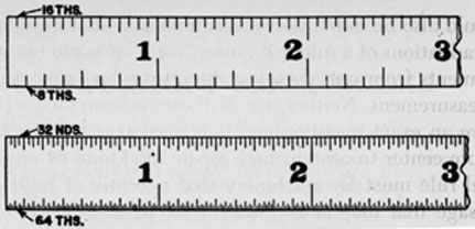
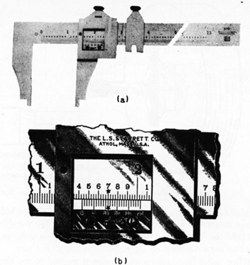
153. Steel Rule.-One of the most frequently used measuring tools is the steel rule, or machinist's rule. This measuring instrument enables work to be laid out accurately, holes located correctly, and distances and sizes measured with precision, and is therefore one of the most important tools in the engine room. It is made from spring steel with a high degree of accuracy in both over-all length and graduations, a 6-inch rule being the most common size, although the 12-inch rule is also used, and there are other standard lengths, up to 48 inches. One side of a steel rule is ordinarily graduated in 8ths and 16ths and the other side graduated in 32nds and 64ths, as shown in Fig. 133.
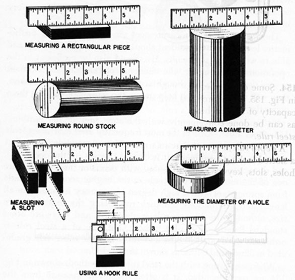
When measuring with the steel rule, the methods shown in Fig. 134 are recommended. It is often helpful to measure from the 1-inch graduation, as demonstrated in the illustration, instead of
150
FIG. 133. Two SIDES OF STEEL RULE.
from the end. Wear and tear are hard on the ends of the rule and it is difficult to measure accurately when starting at that point. Always remember to subtract the correct amount, however. The width of the rectangular piece in Fig. 134, for example, is 434 inches minus 1 inch, or 334 inches.
FIG. 134. MEASURING WITH STEEL RULE.
151
It should also be noted that measurement from inside to inside of the graduations of a rule will give a "scant" measurement, while measurements from outside to outside of graduations will give a "full" measurement. Neither one of these measurements is exact. To secure an exact measurement it is necessary to measure precisely from center to center of the graduation marks.
A steel rule must always be handled carefully. Guard against rough usage that may cause nicks or scratches, as these reduce accuracy. The rule should be stored in a leather sheath when not in use and the leather oiled slightly to prevent rusting and discoloration which would make the graduations difficult to read.
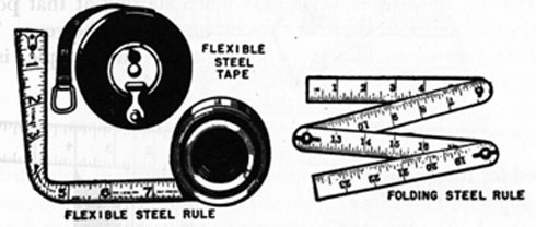
FIG. 135. OTHER STEEL RULES.
154. Some other rules that may be found aboard ship are shown in Fig. 135. These are used for making measurements beyond the capacity of the machinist's rule, or for measuring curved objects, as can be done conveniently with the steel tape or the flexible steel rule.
A depth rule, Fig. 136, has a narrow blade which slides through a slotted locking arrangement. It is used to measure the depth of holes, slots, keyways, and other recesses. Some of these rules can
FIG. 136. DEPTH RULE.
152
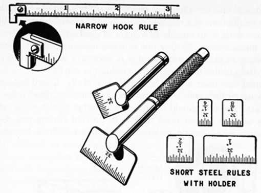
FIG. 137. HOOK RULE AND SHORT STEEL RULES.
be used for measuring angles as well as the depth of holes drilled at an angle to the surface.
The hook rule, Fig. 137, is convenient to use when measuring from an edge, especially an edge that is out of sight. Short steel rules, sometimes called "tempered steel rules," are used where other rules cannot reach. A number of small rule sections are provided as a set, with a long-handled holder. Adjustment is made by a knurled nut at the end of the holder so that the rule can be held at different angles to suit the work.
Outside caliper rules are used to measure the outside diameters of rods, shafts, bolts, etc., in sizes that are within the capacity of their jaws. Inside caliper rules are used to take measurements of slots, grooves and openings.
FIG. 138. COMBINATION CALIPER RULE.
153
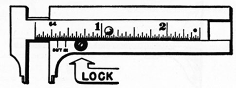
The combination caliper rule, shown in Fig. 138, has jaws designed to make either inside or outside measurements. If the diameter of a hole is being measured, the graduation that lines up with the mark labeled IN is read. When measuring the diameter of a shaft, the graduation that lines up with the OUT mark is read.
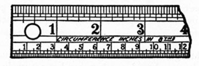
A special type of rule used by some mechanics is known as the circumference rule. The purpose of the rule is to enable the circumference of a piece of work to be obtained without calculation, when the diameter is known. The rule has two sets of graduations on the same face, as shown in Fig. 139. One set is graduated in
FIG. 139. CIRCUMFERENCE RULE.
inches with subdivisions of 1/16 inch, in the standard method, and is used in measuring the diameter. The other is graduated in smaller divisions, the numbers representing inches and the subdivisions representing 1/8 inch, but the spaces are not true length.
To use the circumference rule, read straight across from the diameter measurement to the number on the opposite edge. For example, if it is necessary to cut a piece of sheet metal so that a cylindrical tube 3 1/2 inches in diameter can be made, read directly opposite from 3 1/2 inches and obtain 11. This is the circumference of the tube, in inches, and is very close to the result that would be obtained by calculation, as 3.5 X 3.1416 = 10.9956. It the tube is to be constructed with a lap joint, the material will naturally have to be cut wide enough to allow for the lap.
155. It is important to remember that graduated measuring instruments must be handled carefully so that they will retain their accuracy. In addition they must be kept clean and dry, as dirt and moisture tend to wear and rust away the graduations. Even the touch of the fingers will tend to corrode steel rules. It is therefore essential that they be wiped off with a clean cloth and machine oil after each use, and then stored carefully so as to be protected against damage and deterioration.
154
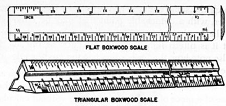
FIG. 140. SCALES.
156. Scales.-The scales shown in Fig. 140 are graduated to indicate proportional rather than actual measurements, permitting them to be used, for example, in laying out work to a scale of 1/4 inch to the foot.
157. Straightedge.-A straightedge is a long, flat, square-edged strip of steel, ground to close tolerances, but not graduated. It is used to enable a perfectly straight line of considerable length to be marked across a flat surface. Where comparatively short distances are involved, a steel scale in good condition can be used as a straightedge. When using a scriber and straightedge, care must be taken to make sure that the point of the scriber is drawn along the guiding edge of the face in contact with the work, as otherwise inaccuracies will result. A straightedge must be handled and stored very carefully. If dents, bends, or rusty spots are permitted to occur, the value of the tool will be seriously affected.
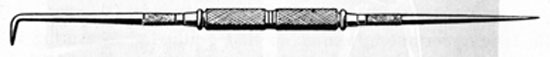
158. Scriber.-A well-sharpened scriber is used to make clean and narrow lines on metal. It is usually a slender piece of tool steel, tapered to a point at each end, with one end being bent to a 90° angle, as shown in Fig. 141. The instrument is long enough so that
FIG. 141. SCRIBER.
it can be gripped in the middle, where it is knurled for that purpose.
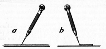
Before using a scriber it is advisable to examine the point, as it must be sharp and evenly ground. An oilstone is used to keep the point in good condition. When using the scriber, hold it firmly,
155
and in much the same manner as a pencil. In Fig. 142 a pocket-type scriber, with a detachable point that may be removed and stored in the head, is shown being drawn along a straightedge. Note that it is tilted slightly in the direction of the line being drawn. Also note how the scriber touches the guiding edge of the lower face of the straightedge.
FIG. 142. USE OF SCRIBER.
It is often advisable to coat the surface of a piece of metal with chalk before drawing lines on it, as this causes the lines to stand out more clearly. The use of chalk is also helpful when using dividers.
159. Dividers.-In order to transfer distances from a rule to the material, dividers are often used. They can also be used to check and compare dimensions, or to scribe arcs and circles.
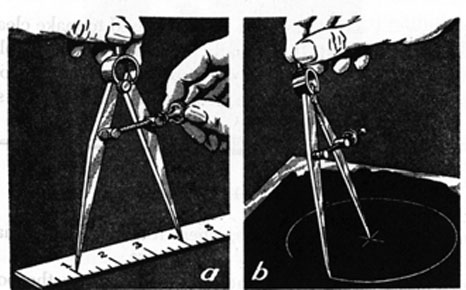
The correct way to set dividers to the desired dimensions is shown in view (a) of Fig. 143. Note that one leg is on the 1-inch
FIG. 143. USE OF DIVIDERS.
156
mark instead of at the end of the rule. Since a 3-inch measurement is desired in this instance, the best method is to compress the legs of the dividers slightly with the hand, and then loosen the adjusting screw until the legs will open slightly wider than 3 inches. Then compress the legs nearly to the correct measurement and tighten up on the adjusting screw, checking and adjusting until one leg stands exactly in the center of the 1-inch graduation and the other leg in the exact center of the 4-inch graduation. If the spring tension is not relieved by compressing the legs as just described, the adjusting screw does all of the work and the threads are subjected to unnecessary wear.
Handle the dividers carefully while in use, as otherwise they may work loose and creep open, thus altering the measurement. Points should be kept sharp by means of an oilstone.
One way to check the setting of dividers is to draw a circle on a piece of scrap paper or metal. Then measure the diameter of the circle with a rule. If the diameter measures exactly twice the desired setting, the dividers are set properly.
When using dividers to scribe a circle or an arc, be sure to tilt the dividers in the direction of the arc, as shown in view (b) of Fig. 143. Keep the dividers at the same inclination throughout the complete circle or arc.
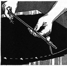
FIG. 144. USE OF TRAMMEL.
160. Trammel.-When it is necessary to mark off an arc or circle too large for dividers, a trammel can be used, as shown in Fig. 144. In this instance the trammel points are attached to an extension bar by means of lock screws. When using the trammel, make sure that there is no sag or bend in the extension bar and that the
157
screws are tight. Incline the trammel in the direction of the arc, and keep the same angle of inclination constant through the entire length of the curve.
A non-adjustable trammel may be used aboard ship when placing the crank of an engine on dead center, as explained in another lesson.
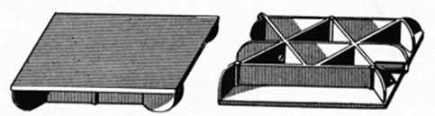
161. Surface Plate.-A surface plate is a flat-topped steel or cast iron plate that is heavily ribbed and reinforced on the under side, as shown in Fig. 145. Its top surface is precision ground to form a true fiat surface, and this surface is used as a base for making layouts with precision tools, such as the surface gage.
FIG. 145. SURFACE PLATE.
The surface plate can also be used for testing machine and engine parts that are required to have fiat surfaces. To do this, a thin film of Prussian blue or some other color pigment is spread evenly over the surface plate. The surface of the part to be tested is then rubbed on the surface plate. The color pigment will adhere to the high spots of the part and indicate the areas to be scraped off. After scraping the high spots, the part is tested again on the surface plate, and the procedure continued until the color distributes evenly over the tested surface, indicating that the job is completed. On large work it may be necessary to lift the surface plate and rub it against the part being tested, but otherwise the procedure is the same.
It is not recommended that a surface plate be used as a means of grinding in flat valves, as this practice would affect the true surface of the plate.
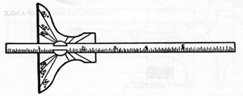
162. Protractor.-The instrument shown in Fig. 146 is known as a protractor and is used in measuring or laying out angles. It is usually made of a transparent substance, such as celluloid, so that lines can be seen through it, but it can be made of metal or other materials. A protractor is made semicircular in shape so as to
158
FIG. 146. PROTRACTOR.
include 180°, and is therefore usually divided into 180 equal parts. each division representing 1°.
By placing the base of the protractor on a line, with the midpoint of the protractor where a second line intersects the first line, the angle between the two lines can be read directly from the instrument. With the aid of a straightedge, or when used in a combination bevel protractor, lines can be drawn on sheet metal, for example, at any desired angle.
The protractor can also be used in the construction of triangles used in mathematical problems, or can be used in the graphical solution of such problems, if the work is done with great care.
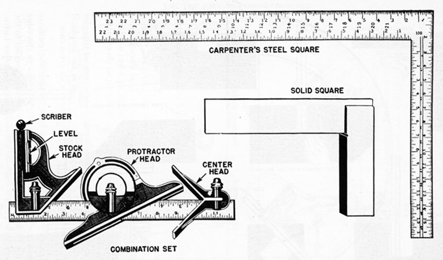
163. Squares and Combination Set.-In order to scribe, measure and check angles, to construct lines at right angles to the edge of a piece of material, to establish points for lines parallel to the edge, and to serve as a guide or reference edge for other instruments, a square is essential. A steel square, 16 X 24 inches, is shown in Fig. 147, also a smaller solid square.
159
FIG. 147. STEEL SQUARE AND COMBINATION SET.
160
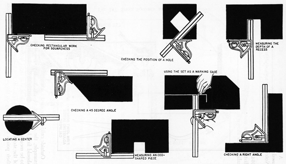
FIG.148. USES OF COMBINATION SET.
161
A combination set is also shown in Fig. 147. This set can be used for various purposes, some of which are shown in Fig. 148. Note that a scriber, a spirit level and a protractor are included.
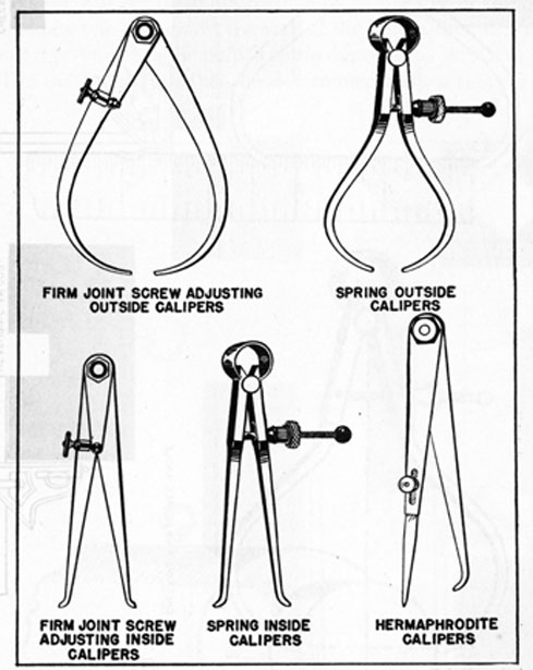
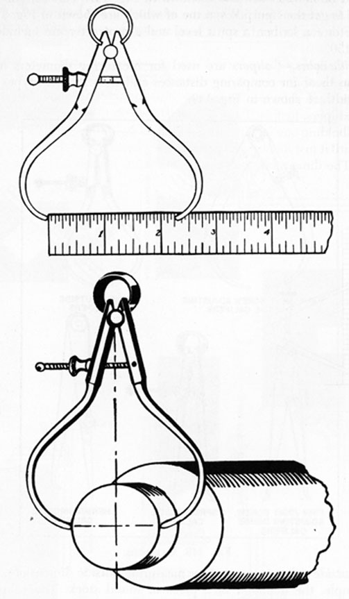
164. Calipers.-Calipers are used for measuring diameters and distances or for comparing distances and sizes. Several types of calipers are shown in Fig. 149.
FIG. 149. CALIPERS.
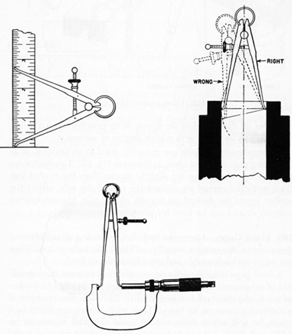
Outside calipers are used for measuring outside dimensions, for example, the diameter of a piece of round stock. The calipers should first be set approximately to the diameter of the material to be measured. Then, while held at right angles to the center line of the stock, as shown in Fig. 150, the calipers are adjusted until their points bear lightly on the surface of the work. The points
162
FIG. 150. MEASURING WITH OUTSIDE CALIPERS.
163
should be moved back and forth slowly while adjusting them, in order to get the "feel." When the adjustment has been made, the diameter can be read from a rule as shown in the upper part of Fig. 150.
Inside calipers have curved legs for measuring inside diameters, such as the diameters of holes, the distance between two surfaces, the width of slots, etc. To measure the diameter of a hole with inside calipers, first set them approximately to the size of the hole; then, holding one leg against the wall of the hole, adjust the other leg until it just touches the point exactly opposite, as shown in Fig. 151. The dimension can then be determined with a rule, or
FIG. 151. MEASURING A DIAMETER WITH INSIDE CALIPERS.
164
FIG. 152. HERMAPHRODITE CALIPERS.
micrometer, as illustrated in the figure. With practice, such a measurement can be taken with a high degree of accuracy.
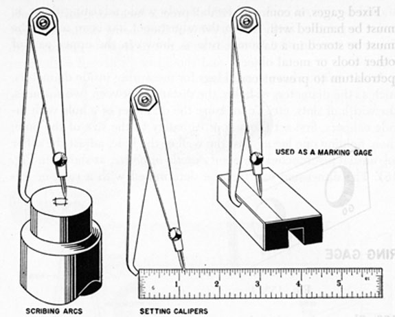
Hermaphrodite calipers are generally used to scribe arcs, or as a marking gage in layout work, as shown in Fig. 152. To adjust them to a rule, set the scriber leg slightly shorter than the curved leg; then, with the curved leg against the end of the rule, adjust the scriber leg to the desired graduation on the rule. Hermaphrodite calipers should not be used for precision measurements.
165. Fixed Gages.-Gages are tools for measuring or transferring distances or dimensions, usually within 0.001 inch or less. They are made both adjustable and nonadjustable, or fixed.
A fixed gage is made with extreme accuracy to some fixed standard of measurement or shape, so that when it is applied to a piece of work, the standard is transferred to the work. For example, if a mechanic wants to fix two surfaces so that they are 0.006 inch apart, he will adjust them until a piece of metal known to be 0.006 inch thick will just fit between them. Such a piece of metal would be a fixed gage.
165
Fixed gages, in common with all precise measuring instruments, must be handled with care to prevent their being damaged. They must be stored in a case or box so as not to come in contact with other tools or metal objects, and should be protected with oil or petrolatum to prevent corrosion.
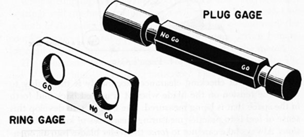
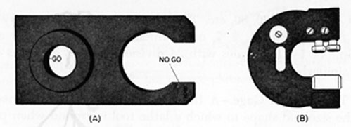
FIG. 153. PLUG GAGE AND RING GAGE.
166. Plug gages and ring gages, examples of which are shown in Fig. 153, are used in production work to check inside and outside dimensions for size and to see that finished parts are within the manufacturing tolerance. (Tolerance in this case means the allowable variation in a dimension that is permissible without rejection of the finished part when inspected.) Such gages are usually made in pairs, either in one piece or two units. For instance, a plug gage generally has a "go" end and a "no go" end. If the "go" end of such a gage will enter a finished hole and the "no go" end will not, the size of the hole is within the tolerance for which the gage was designed.
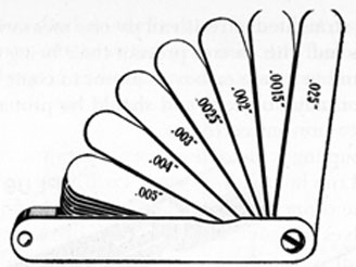
167. Feeler Gage.-A feeler, or thickness, gage, shown in Fig. 154, resembles a pocket knife with a number of blades. All of the blades have the same shape, but each blade is accurately ground to a definite thickness, which is stamped on the blade.
Feeler gages are used to measure the distance between two surfaces, for example, when determining bearing clearances, valve tappet clearances, etc. The feeler gage blades usually range in thickness from 0.0015 inch to 0.025 inch. By selecting combinations of two or more blades it is possible to measure clearance up to the total thickness of all of the blades.
166
FIG. 154. FEELER GAGE.
The secret of checking clearances accurately is the ability to "feel" the tension on the blade when it is moved back and forth in the space that is being measured. The best way to develop this sense of feel is to practice measuring clearances of known dimensions. Always take care not to force the feeler blades into an opening.
The thinner blades must be handled with particular care to prevent kinks and creases. When using the thinner blades in combination with other blades, always protect the thin blades by placing them between heavy blades. Wipe the blades with a clean cloth before using them, otherwise they will not measure accurately. After using the feelers, wipe each blade clean and then apply a protective coating of oil or petrolatum. Remember that feeler gages are easily corroded by perspiration applied during handling, and if carried around in the pocket or otherwise neglected after use, the blades may rust together.
A typical use of a feeler gage, in addition to those previously stated, would be in lining up or checking the alignment of a shaft coupling. When this is to be done, all coupling bolts and nuts are removed and a straightedge is placed across the outer surface of the two coupling halves, in line with the shaft. The straightedge should rest evenly across the rims of both coupling halves. If it does not rest evenly across the coupling and clearance is noted, the coupling is out of line. Tests should be made with the straightedge at 90-degree intervals around the circumference of the coupling.
A feeler gage should next be used to measure the clearance between the faces of the coupling halves, the clearance also being measured at 90-degree intervals around the circumference. All four measurements should be equal.
167
When the straightedge rests evenly on both coupling halves in all four tests and the clearance between the coupling halves is equal in all measurements, the coupling is properly aligned. However, if there is any discrepancy in either test, the coupling is misaligned.
When a coupling is out of line, noisy operation is likely to occur, bearings will run hot, packing glands will wear and leak, etc. One or both of the connected units therefore must be moved until the coupling halves are aligned. In the case of motor-driven pumps, for example, it is usually more convenient to move the motor.
The alignment of a coupling may also be determined by the use of a machinists', or dial, indicator. This instrument is described later.
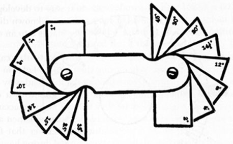
FIG. 155. ANGLE GAGE.
168. Angle and Radius Gages.-The blades of angle and radiusgages are all of the same thickness, hut with them it is the blade outline that is important. Each blade of an angle gage, for example, has a different end angle, as shown in Fig. 155, and these gages are used when it is necessary to measure the same angles frequently.
The rounded corner of each blade of a radius gage is the arc of a circle, and the radius of the arc is stamped on the blade, as shown in Fig. 156. The gage can be used to check outside radii as well as inside radii.
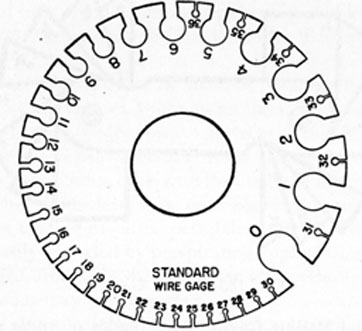
169. Wire and Sheet Gage.-The gage shown in Fig. 157 is a U. S. Standard wire and sheet gage. It can be used to measure
168
FIG. 156. RADIUS GAGE.
FIG. 157. WIRE AND SHEET GAGE.
cross sections of wire and to determine the gage (thickness) of metal sheets. Before using one of these gages be sure that all burrs are removed from the material being measured.
170. Snap Gage.-A snap gage is used to check the outside diameters of shafts on which it is impossible (because of construction) to use a ring gage. The gage shown in Fig. 158 (A) is a combination snap and ring gage.
Adjustable snap gages have anvils that can be set to the desired dimensions by means of a micrometer or gage blocks. The gage
169
FIG. 158. SNAP GAGES.
shown in Fig. 158 (B) has two adjustable anvils; one can be set for the allowable minimum diameter and the other for the allowable maximum diameter.
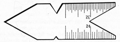
171. Center Gage.-The gage shown in Fig. 159 is a 60° center gage. The notches in the edge of this gage also have an angle of 60° and are used to check the grinding of thread-cutting tools, as American National thread has a thread angle of 60°. The center gage can also be used for setting thread-cutting tools square with the work.
FIG. 159. CENTER GAGE.
Center gages are usually marked on both faces and along both edges with scales that are convenient for measuring the number of threads per inch of bolts, studs, etc. One face has 20 divisions to the inch on one edge and 14 divisions to the inch on the other edge. On the opposite face of the center gage there are 24 divisions per inch on one edge and 32 divisions per inch on the other edge. The different sized divisions are used to check the pitch, or number of threads per inch, of screw threads. The different numbers of threads per inch for which each scale is suitable are those which divide into the scale number without a remainder. For example, the edge with 20 divisions is suitable for measuring 1, 2, 4, 5, 10 and 20 threads per inch, and also for any multiple
170
of 20, such as 40, 60, 80, etc. The edge with 14 divisions may be used for measuring 1, 2, 7, or 14 threads per inch and for any multiple of 14. The scales with 24 divisions and 32 divisions are used similarly.
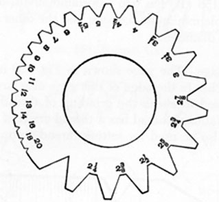
172. Thread Tool Gage.-A thread tool gage is useful in checking the size and shape to which a lathe tool is ground when preparing it to cut a thread. A thread tool gage for American National Coarse (NC) thread is shown in Fig. 160. Each notch of the gage
FIG. 160. THREAD TOOL GAGE.
is shaped for a particular thread, the figure opposite each notch
denoting the number of threads per inch. The threading tool is
ground to fit the notch corresponding to the thread that is to be cut.
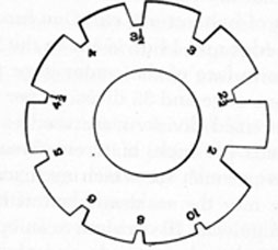
A worm-thread tool gage is shown in Fig. 161. This type of gage
is used to check the shape and size of a tool used to cut worm
FIG. 161. WORM-THREAD TOOL GAGE.
threads, the numbers indicating the number of threads per inch.
173. Surface Gage.-A surface gage is used to measure height and for scribing layout lines on vertical surfaces. The commonly used universal type, Fig. 162, has a base plate, an adjustable extension
FIG. 162. SETTING A SURFACE GAGE.
arm, and an adjustable scriber. When a surface gage is set to a combination-square rule, as shown in the illustration, both the square and the gage base must rest on a flat smooth surface, preferably a surface plate.
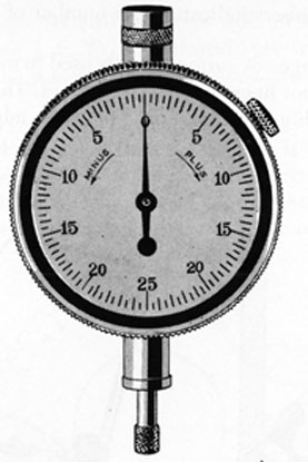
174. Machinists' Indicator.-A machinists' indicator is a measuring instrument used to test or measure variations in dimensions, the changes in measurements being indicated visually by means of a pointer and a scale or dial. When arranged with a dial, this type of instrument is known as a dial indicator. The indicator shown in Fig. 163 gives readings in thousandths of an inch. It is often helpful to mount a dial indicator on the extension arm of a surface gage, or make some other suitable arrangement, and use the set-up to check the trueness of work in a lathe, the deflection of a shaft, the alignment of couplings, etc. By setting the indicator in position with its contact stem bearing against a shaft, for example, the shaft can be turned slowly, and if it does not run true, the dial hand will indicate the deviation. In operation, the instrument can be adjusted so that it reads zero at the beginning of the
172
FIG. 163. DIAL INDICATOR.
reading. When the shaft or other piece of work is rotated, if the total of the maximum plus and minus readings should be 0.004 inch, for example, the actual deflection would be 0.004 / 2 = 0.002 inch.
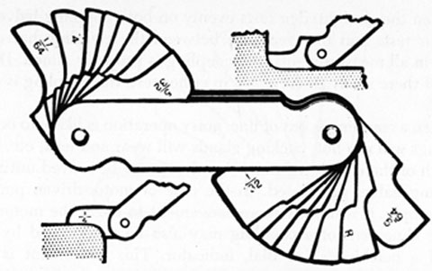
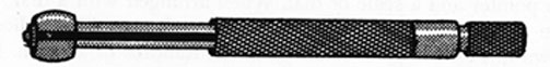
175. Small-Hole Gages.-One common method of finding the diameter of a small hole is to try various twist drills in it until one is found that just fits in the hole. This method is satisfactory if the right drill is available and absolute accuracy is not all-important.
The split-ball type of small-hole gage, Fig. 164, is designed,
FIG. 164. SMALL-HOLE GAGE.
however, for accurate determination of the diameters of small holes. There are usually four of these gages in a set, designed to measure any hole diameter up to 1/2 inch. To use the gage, the ball end is placed in the hole and the two halves expanded by turning the handle. When the "setting" is just right, the gage is locked by means of the knob at the end of the handle. The gage is
173
then withdrawn from the hole and the diameter of the ball end measured with a micrometer.
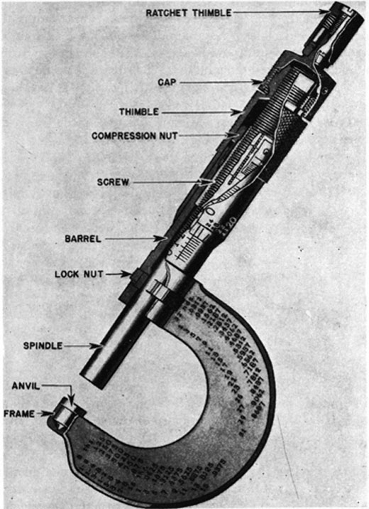
176. Micrometers.-The micrometer, or micrometer calipers, is the most commonly used adjustable gage and it is important that its mechanical principles, construction, use and care, be thoroughly understood. A 1-inch outside micrometer, with its various parts indicated, is shown in Fig. 165.
FIG. 165. SECTIONAL VIEW OF 1-INCH OUTSIDE MICROMETER.
174
Micrometers are commonly used to measure distances to 1/10,000 inch (0.0001 inch) and the measurements are usually expressed or written as a decimal. Any person using a micrometer, therefore, should be entirely familiar with the method of writing and reading decimals. As a brief review, remember that all figures to the left of the decimal point are whole numbers; all figures to the right of the decimal point indicate parts of whole numbers. Starting from the decimal point and moving to the right, the first digit indicates tenths; the second, hundreths; the third, thousandths; the fourth, ten-thousandths; and so on. Thus 2.000 inches indicates exactly 2 inches; 2.3 is read two and three-tenths; 1.85 is read one and eighty-five hundredths; 4.071 is read four and seventy-one thousandths; and 0.2318 is read two thousand three hundred eighteen ten-thousandths. When there is no number to the left of the decimal point, the quantity indicated is less than 1.
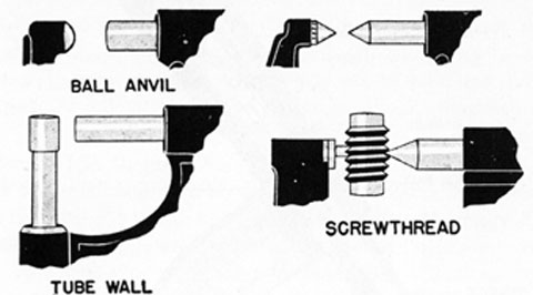
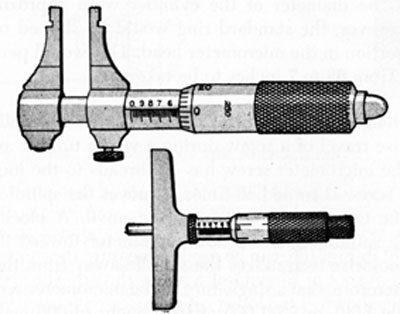
177. Types of Micrometers.-Micrometers are made in several different types, as shown in Figs. 166, 167, and 168.
FIG. 166. SPECIAL OUTSIDE MICROMETERS.
The outside micrometer is used for measuring outside dimensions, such as the diameter of a piece of round stock. The inside micrometer is used for measuring inside dimensions, such as the bore of a cylinder. The screw-thread micrometer shown at the upper right in Fig. 166, can be used to measure the minor diameter (diameter at root of thread) of a screw thread. The screw-thread micrometer shown at the lower right is used to determine the pitch diameter of a screw thread. The depth micrometer is used to
175
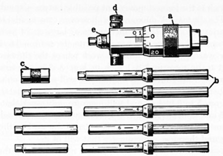
a. micrometer head
d. lockscrew
b. extension rods
d. lock screw
c. standard ring
e. collar
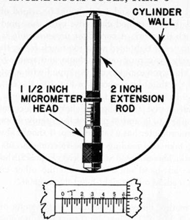
FIG. 167. INSIDE MICROMETER.
measure the depth of holes or recesses. The ball-anvil micrometer can be used to measure the thickness of tubing or bearing inserts, the ball shape fitting the contour of a cylindrical shape and reducing the possibility of damage to soft bearing metal. The tube-wall micrometer is also suitable for measuring the thickness of tubing.
178. Range of Micrometer.-Micrometers are usually made so
FIG. 168. 1-INCH INSIDE MICROMETER AND DEPTH MICROMETER.
176
that 1 inch is the longest movement possible between spindle and anvil. The frames of micrometers, however, are available in a wide variety of sizes, from 1 inch up to as large as 24 inches for special work. The range of a 1-inch micrometer is from 0 to 1 inch; in other words, it can be used on work where the dimension of the part to be measured is 1 inch or less. A 2-inch micrometer has a range from 1 inch to 2 inches, and will measure only work that is between 1 and 2 inches thick. A 6-inch micrometer has a range from 5 to 6 inches, and will measure only work that is between 5 and 6 inches thick. It is necessary, therefore, in selecting a micrometer, to find the approximate size of the work to the nearest inch and then use a micrometer that will fit it.
When it is necessary to use an inside micrometer of the type shown in Fig. 167, an extension rod of the correct size must first be inserted in the micrometer head. The extension rod used must be the one that will enable the micrometer to measure the desired dimension. As the micrometer shown in the illustration has a movement of only 1/2 inch, a standard ring, which can be slipped over the extension rod, thus moving the collar 1/2 inch from the micrometer head, is provided. This permits an additional adjustment of 1/2 inch to be obtained. The combination of various parts therefore enables various measurements to be taken, within the range of the instrument.
To measure a cylinder with a diameter of approximately 6% inches, for example, the extension rod labeled "6 - 7" would be used, and the range of the instrument would be from 6 to 6 1/2 inches. If the diameter of the cylinder were approximately 6 3/4 inches, however, the standard ring would be slipped on the rod before insertion in the micrometer head. This would permit measurements from 6 1/2 to 7 inches to be taken.
179. Mechanics of Micrometer.-A micrometer actually records the endwise travel of a screw during a whole turn or any part of a turn. The micrometer screw has 40 threads to the inch, that is, when the screw is turned 40 times, it moves the spindle exactly 1 inch either toward or away from the anvil. A clockwise turn moves the spindle of an outside micrometer toward its anvil; a counterclockwise turn moves the spindle away from the anvil. It is clear, therefore, that a single turn of the micrometer screw moves the spindle 1/40, or 25/1,000 (0.025) inch. (1.000 inch / 40 = 0.025 inch.)
177
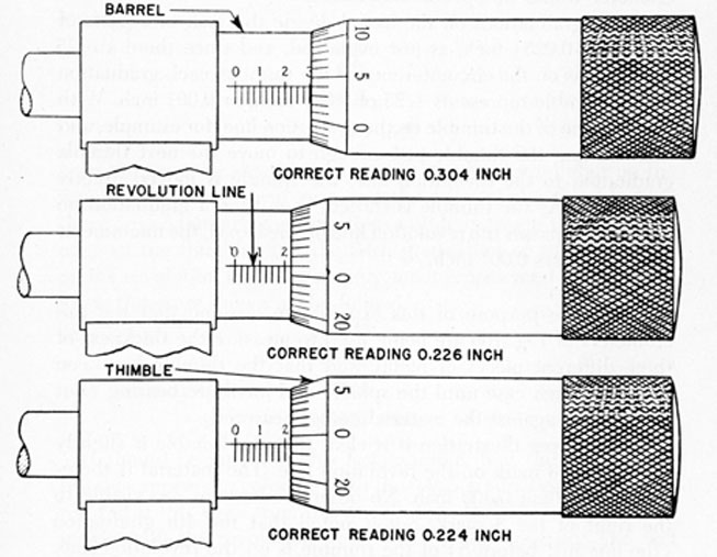
180. Reading the Micrometer.-As just explained, if the thimble of a micrometer is turned through one complete revolution, the micrometer opens or closes 0.025 inch. Hence, to change the opening distance of 0.001 inch, the thimble should be turned through only 1/25 of a revolution. To measure in thousandths of an inch by using the micrometer, therefore, the problem involved is to count the number of complete revolutions, plus any part of a revolution, in twenty-fifths, that the thimble makes to set the spindle and anvil exactly against the work being measured. For this purpose, the barrel and thimble of micrometers are marked as shown in Fig. 169.
FIG. 169. READING THE MICROMETER.
The revolution line on the barrel should be understood first. It is graduated in 40 divisions, each 0.025 inch in width, and a complete revolution of the thimble moves the thimble exactly 0.025 inch along the barrel, or from one graduation to the next. The spindle moves the same distance and in the same direction. Two complete revolutions move the thimble 0.050 inch, 3 revolutions 0.075 inch, and 4 revolutions 0.100 inch (1/10 inch). The numbers
178
at every fourth graduation on the revolution line therefore indicate tenths of an inch, and there are 10 such numbers.
Assume, for example, that the micrometer is in the closed position, and the thimble is then turned counterclockwise through 4 whole revolutions. When this has been done, the edge of the thimble would exactly coincide with the fourth graduation (marked 1) on the revolution line, and the opening between the spindle and the anvil would be 1/10 inch. If the thimble were turned further until the edge coincided with the next (fifth) graduation on the barrel, 5 revolutions would have been made and the micrometer would be opened 0.125 inch.
As the graduations on the barrel divide the inch into parts of 25/1,000 (0.025) inch, as just explained, and since there are 25 graduations on the circumference of the thimble, each graduation on the thimble represents 1/25 of 0.025 inch, or 0.001 inch. With the zero line of the thimble on the revolution line, for example, and then turning the thimble just enough to move the next thimble graduation to the revolution line, the spindle is moved exactly 0.001 inch. As the thimble is turned, each time a graduation on the thimble passes the revolution line on the barrel, the micrometer opens or closes 0.001 inch.
181. For the purpose of this explanation, assume that the micrometers of Fig. 169 are being used to measure the thickness of three different pieces of metal, and that the thimble has been turned in each case until the spindle and anvil are bearing (but not forced) against the material being measured.
In the upper illustration it is clear that the thimble is slightly outside the 3 mark on the revolution line. The material is therefore larger than 0.300 inch. No other graduations are visible to the right of the 3 mark, hut is noted that the 4th graduation (the one just before 5) of the thimble is on the revolution line. The measurement is therefore 0.304 inch, as demonstrated in the following:
0.300
(largest number on revolution line between zero and edge of thimble)
0.000
(no graduations between 3 and edge of thimble) 0.004 (number of graduations on thimble between zero and revolution line)
-----
0.304
inch
179
In the middle illustration of Fig. 169, the largest number on the revolution line between zero and the edge of the thimble is 2, which represents 0.200 inch. Then it is necessary to add the distance represented by the number of unmarked graduations between the 2 and the edge of the thimble. Although not clearly shown in the illustration, the thimble has just uncovered a graduation line, which represents an additional 0.025 inch. The zero on the thimble has also passed the revolution line in the opening direction, and the first graduation on the thimble is on the revolution line. The total opening of the micrometer, and therefore the thickness of the material being -measured, is shown in the following:
0.200
0.025
0.001
----
0.226 inch
In the lower illustration of Fig. 169, the largest number on the revolution line between zero and the edge of the thimble is 2; there are no unmarked graduations visible between the 2 and the edge of the thimble; and the 24th graduation of the thimble is on the revolution line. The measurement represented by the reading is therefore shown in the following:
0.200
0.000
0.024
----
0.224 inch
It should be noted, in this last example, that the edge of the thimble appears to coincide with the 0.025 graduation on the barrel; but if this were true, the zero line on the thimble would coincide with the revolution line, which it does not do. The fact that the 24th graduation of the thimble is on the zero line shows that the 0.025-inch graduation on the barrel has not been reached. In the middle illustration of Fig. 169, however, the fact that the 1st graduation of the thimble is on the zero line presents evidence that the 0.025-inch graduation on the barrel has been reached.
182. In each of the illustrations of Fig. 169, one of the thimble graduations is exactly aligned with the revolution line. This
180
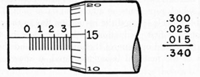
alignment will not always occur in actual practice; in many cases when the measurement is taken the thimble graduation will be at one side of the revolution line. An example of this type of reading is shown in Fig. 170, where the revolution line is between the 14th and 15th graduations of the thimble.
FIG. 170. READING BETWEEN LINES.
For reasonable accuracy the reading of Fig. 170 can be taken to the nearest graduation, the 15th. The reading in this case would be:
0.300
0.025
0.015
----
0.340 inch
For closer work, however, the position of the revolution line relative to the thimble graduations can be estimated. In this case it is about 7/10 of one graduation past the 14th graduation, and the reading can be taken as:
0.300
0.025
0.014
0.0007
----
0.3397 inch
183. Vernier.-In the illustrations of Figs. 169 and 170, the micrometers are constructed to take measurements to 1/1000 inch, measurements less than 1/1,000 inch being estimated, as explained in the preceding article. Many micrometers, however, have a vernier scale on the barrel, enabling measurements to be taken to 1/10,000 inch.
The fundamental idea of a vernier scale is to divide a line of known length into equal parts, and to compare the size of the divisions with those on a line the same length as the first one, but
181
FIG. 171. VERNIER SCALE MICROMETER.
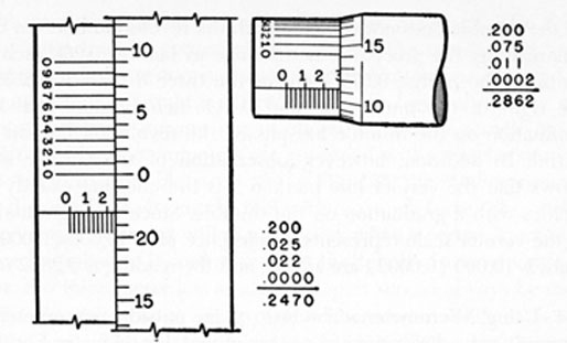
divided into one less part. This is illustrated in Fig. 171, the left-hand view representing the barrel and thimble of a micrometer, but flattened out for the purpose of this explanation. The graduations, marked 0, 1, 2, 3, 4, 5, 6, 7, 8, 9, 0, on the barrel, comprise the vernier scale.
Observe that 10 divisions of the vernier are exactly equal to 9 divisions on the thimble. Since each division on the thimble represents 0.001 inch, each division on the vernier represents 0.0009 inch. This is shown as follows:
9 X 0.001 / 10 = 0.0009
It is apparent, therefore, that each division on the vernier represents a distance 0.0001 inch smaller than is represented by each division on the thimble. It can also be seen in Fig. 171, that when zero on the vernier coincides with zero on the thimble, the next graduation on both vernier and thimble will be 0.0001 inch apart, the second pair will be 0.0002 inch apart, and so on, until the graduations coincide again at zero on the vernier.
When the zeros of the vernier exactly coincide with lines on the thimble, a line on the thimble also exactly coincides with the revolution line on the barrel, and the reading is in thousandths. This is the condition shown in the left-hand view of Fig. 171, where the reading is 0.2470 inch.
In the right-hand illustration of Fig. 171, however, the zero lines of the vernier do not exactly coincide, and the graduation
182
on the thimble does not coincide with the revolution line. To take this reading, the procedure is the same as before: 0.200 inch for the 2 on the barrel; 0.075 inch for the three divisions visible to the right of the number 2; and 0.011 inch because the 11th graduation on the thimble has passed the revolution line on the barrel. In addition, however, observation of the vernier scale shows that the vernier line marked 2 is the one that exactly coincides with a graduation on the thimble. Since each graduation of the vernier scale represents a difference of 1/10,000 (0.00001) inch, 2/10,000 (0.0002) are added, and the reading is 0.2862 inch.
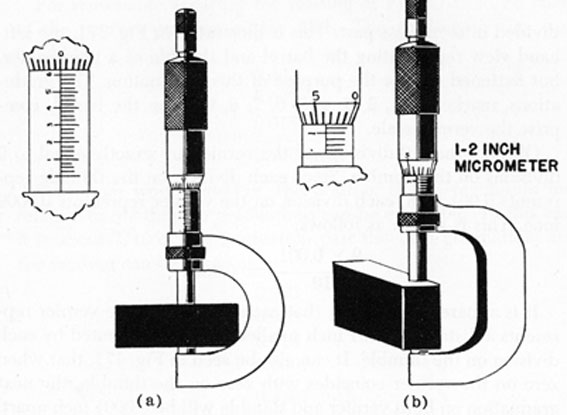
184. Using Micrometer.-The use of an outside micrometer in measuring the dimensions of a piece of metal is shown in Fig. 172.
FIG. 172. USE OF MICROMETER.
As explained previously, a micrometer of the correct size for the work must be selected. In view (a) of Fig. 172 a 1-inch micrometer is used because the material is less than 1 inch in thickness. In view (b) a 2-inch micrometer is used because the dimension is between 1 and 2 inches.
The piece of work to be measured should be wiped clean. The micrometer should be opened wide enough to slip over the work
183
freely, and the spindle and anvil should be wiped off. The thimble should then be turned clockwise until the spindle and anvil lightly touch the work. A very light pressure only is required. If the micrometer is tightened with too much force, the frame will almost surely be sprung out of shape and readings will be inaccurate. Many micrometers are equipped with a ratchet stop on the end of the thimble, as shown in Fig. 165, the ratchet preventing the user from closing the tool with too much force. The ratchet stop is made so that it will slip and click when a certain amount of force is applied to it, and so prevent the spindle from moving further. If a micrometer has a ratchet stop, it should always be used.
Finally, take the reading of the micrometer while it is still on the work. The enlarged view in (a), Fig. 172, shows the reading on the left-hand micrometer, and the other enlarged view shows the reading on the right-hand micrometer.
185. The methods used in measuring the diameter of round stock are shown in Fig. 173. When the correct size micrometer has been selected, the procedure is the same as in measuring a piece of material with flat surfaces. Care should be taken, however, to insure that the material is measured at points exactly opposite each other; this is done by sliding the micrometer back and forth across the piece until the right "feel" is obtained. Note that a micrometer which measures dimensions between 16 and 17 inches is used in (b), Fig. 173.
FIG. 173. MEASURING ROUND STOCK.
184
FIG. 174. MEASURING INSIDE DIAMETER.
186. The correct use and position of an inside micrometer when taking the inside measurement of a small cylinder are shown in Fig. 174. As explained previously, the first step in the measurement is to find the approximate diameter with a rule; then select the correct extension rod and insert it in the micrometer head. Be sure that both the rod and micrometer head are thoroughly clean, and that the rod is screwed in the full distance. Neglect of either of these precautions may result in an inaccurate measurement.
In order to use this type of inside micrometer it is necessary to know the length of the micrometer head, which in this case is M inches, when in the closed position. The instrument is also equipped with a 4-inch head for longer measurements. The micrometer heads have a range of 1 inch.
The length of each extension rod is stamped on the rod, a common set including rods from 1 inch to 14 inches in length, thus enabling the instrument to measure distances from 1 1/2 inches to 19 inches.
To "mike" the cylinder illustrated in Fig. 174, since measurement with a rule has shown the diameter to be somewhere between 4 and 4 1/4 inches, the 2-inch extension rod is used, as it will enable the tool to measure distances from 3 1/2 to 4 1/2 inches.
185
When the extension rod has been properly inserted in the micrometer head, place the end of the rod against one side of the cylinder and turn the thimble of the micrometer until the head barely touches the other side at a point exactly opposite. Then read the dimension while the micrometer is still in position. Never let the micrometer bear heavily enough to hang in the work with the hands removed from it.
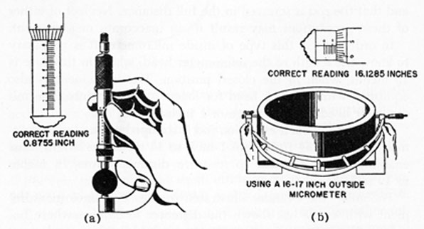
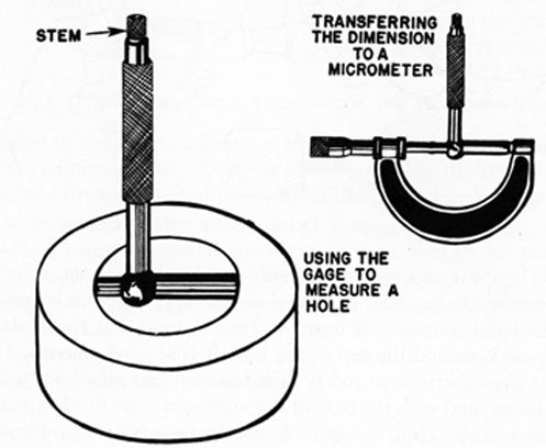
187. Another method used for measuring smaller work, where an inside micrometer will not fit conveniently, is to use a telescoping gage, as shown in Fig. 175. The telescoping gage should
FIG. 175. TELESCOPING GAGE.
be adjusted in the work until it exactly touches points directly across from each other, and is then locked by turning the stem. When this has been done, the gage is removed and the dimension measured with an outside micrometer as shown in the upper view of Fig. 175.
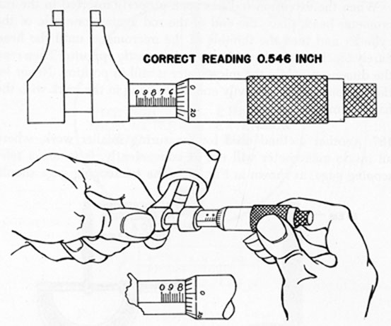
For very small holes, the small inside micrometer shown in Fig. 168 is convenient. The use of this tool is demonstrated in Fig. 176, and the two different readings show that it is read like other micrometers, except that the numbers on the barrel increase toward the left instead of toward the right.
186
FIG. 176. MEASURING DIAMETER OF SMALL HOLES.
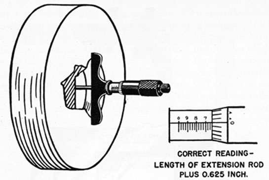
188. When it is necessary to measure the depth of a hole, a depth micrometer can be used, as shown in Fig. 177. Before taking this measurement, remove all burrs and make sure that the surface of the work around the top of the hole is clean and smooth. The correct size of extension rod is then selected and attached to the micrometer, and with the base of the micrometer set firmly against the flat surface, turn the thimble clockwise until the extension rod just touches the bottom of the hole. If the micrometer is equipped with a ratchet stop, it should be used. The measurement is read in the usual manner.
189. As the micrometer is a delicate precision tool, every precaution should be taken to prevent damage to it. Handle it with care and do not allow it to become rusty or dirty. After it has been used, wipe it off with a clean cloth to which a few drops of fine machine oil have been added. When not actually in use, keep the micrometer in a wooden or metal box, with a felt lining.
Micrometers are often ruined by being closed too tightly on the material measured. Remember that only a very light pressure is
187
FIG. 177. USE OF DEPTH MICROMETER AND EXTENSION ROD.
needed to obtain an accurate measurement. Also, always hold the frame stationary and adjust the tool by turning the thimble. Do not hold the thimble and swing the frame around in order to open or close a micrometer.
When using large micrometers, care is needed to see that the frames are not handled roughly or sprung out of shape. When working with the larger micrometers in cold weather, it is good practice to use a piece of cloth or waste between the hand and the frame, as the heat of the hand may expand the frame enough to cause a variation in the reading.
190. Vernier Calipers.-A vernier caliper, Fig. 178 (a) , resembles a caliper rule and is used for the same purpose. The difference, however, is that the vernier caliper can make precision measurements because it has its own vernier scale.
The blade of one common type of vernier caliper has a scale that is divided into inch spaces. These spaces are sub-divided into spaces of 1/10 (0.100) inch and 1/40 (0.025) inch. The sliding jaw carries the vernier scale, and this scale has 25 spaces, each of which is only 0.024 inch, 0.001 inch less than a space on the blade scale. (There are actually two vernier scales on the sliding jaw, one marked "outside" for outside measurements, and the other marked "inside" for inside measurements.)
To take a measurement with the vernier caliper, first set the
188
FIG. 178. VERNIER CALIPER.
caliper to the thickness or diameter of the material being measured, and lock the sliding jaw to the blade with the knurled-head set screw. Then read the blade scale toward the right, Fig. 178 (b), and record the reading of the last graduation on the left of the zero of the vernier scale. In this particular instance the last graduation on the left of vernier zero represents 1.425 inches. Then carefully examine the vernier scale, Fig. 178 (b), and it will be seen that the 11th graduation on the vernier exactly coincides with a graduation on the blade. The reading is therefore as follows:
1.425
0.011
----
1.436 inches
Vernier depth gages are set and operated in much the same way as a vernier caliper. The vernier principle is also applied to a number of other gages, instruments and tools.
189
191. Gage Blocks.-Gage blocks are rectangular pieces of tool steel, having two measuring surfaces which are flat, parallel with each other, and a predetermined distance apart, the distance being accurate to within 0.000002 (two millionths) inch. These blocks are so exactly machined, finished and lapped, that if the measuring surfaces of any two of them, when thoroughly clean, are slid together with a slight inward pressure, they will adhere to one another as though magnetized. Gage blocks (sometimes called jo-blocks, from Johanson, their originator) are available in three grades of accuracy:
1. Laboratory set, AA quality, accurate to 0.000002 inch.
2. Inspection set, A quality, accurate to 0.000004 inch.
3. Working set, B quality, accurate to 0.000008 inch.
A full working set of gage blocks is made up of 81 blocks. The set consists of four series of sizes, as follows:
1. First series. 9 blocks, ranging in size from 0.1001 inch to 0.1009 inch, in steps of 0.0001 inch.
2. Second series. 49 blocks, ranging in size from 0.101 inch to 0.149 inch, in steps of 0.001 inch.
3. Third series. 19 blocks, ranging in size from 0.050 inch to 0.950 inch, in steps of 0.050 inch.
By sliding different sizes of blocks together, the machinist can obtain any measurement, in 1/10,000 of an inch, from 0.1001 inch to 12.00 inches, and in 1/1,000 of an inch, from 0.100 inch to 12.00 inches.
Gage blocks are commonly used for checking the accuracy of other gages, such as snap gages or micrometers, although it is practical to use them directly on a piece of work to be measured.
If it is desired to check the accuracy of a micrometer, any block or combination of blocks within the range of the micrometer can be used. Wipe the measuring surfaces clean on the hand or a piece of chamois, and slide them together so that they adhere. Then measure the thickness of the gage blocks with the micrometer being tested. If the micrometer reading agrees with the known thickness of the gage blocks, the micrometer is accurate.
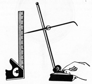
192. Speed Indicator.-When it is desired to know the number
190
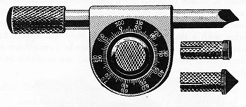
of revolutions per minute made by an electric motor, turbine rotor, or other revolving part, the information can be secured by the use of a speed indicator, such as shown in Fig. 179.
FIG. 179. SPEED INDICATOR.
This type of speed indicator has a spindle that is free to turn in the body of the instrument, the spindle being geared to the graduated ring in such a way that 100 turns of the spindle cause the ring to make exactly one complete revolution. The ring is graduated into 100 equal parts, and is numbered both right-handed and left-handed, so that the indicator may be used on a shaft that is turning in either direction.
The indicator has a set of interchangeable rubber tips that fit on the spindle. Cone-shaped, flat end and vacuum tips are usually supplied. The cup-like vacuum tip works best on the flat end of a shaft; the cone tip is best when the shaft has a countersunk end.
In order to use this type of speed indicator, a stop watch or a watch with a sweep second hand is needed. Then slip the correct tip over the end of the spindle and apply the tip to the rotating shaft. When the zero is observed to pass under the starting mark, an assistant should start the stop watch. The number of times that the zero passes the starting mark is then counted. When a minute (or any other desired period of time) has elapsed, the indicator is quickly removed from the shaft and the position of the ring noted. If, for example, the ring has made 17 revolutions during the minute and the 60 graduation stands under the starting mark, the reading is taken as 1,760 rpm.
Another type of speed indicator has a small pin on its graduated ring, and is equipped with a notched disk. Every time the graduated ring makes a complete turn, the pin on it passes under a spring finger, lifting the spring finger and allowing the notched
191
disk to move one notch. At the end of the test the number of notches that the notched disk has moved is counted. Each notch represents 100 revolutions of the spindle.
Some speed indicators are equipped with a small rubber-faced wheel which can be slipped on the spindle. The wheel is used when it is desired to find the speed, in feet per minute, at which the surface of a piece of work is moving. To do this, the wheel is pressed against the face of the work whose surface speed is to be found, holding the spindle parallel to the face of the work and noting the elapsed time carefully. The wheel is generally of such a size that every revolution of it represents a movement of 6 inches (1/2 foot) of the surface of the work. The total reading of the indicator, for 1 minute, is therefore divided by 2, and the result is the speed of the surface of the work, in feet per minute.
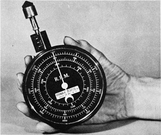
193. Tachometer.-A tachometer differs from the speed indicators previously described, in that it registers directly the revolutions of the rotating shaft, no timing or computation being necessary. A tachometer designed for use with either high, medium, or low-speed machinery is shown in Fig. 180. To use this tachometer on
FIG. 180. TACHOMETER.
192
an alternator operating at 3,600 rpm, for example, the gear shift would be set in the HIGH position and the reading taken from the outer graduated circle. For a machine operating at 800 rpm, the tachometer gear shift would be set in the LOW position and the reading taken from the next to the outer graduated circle.
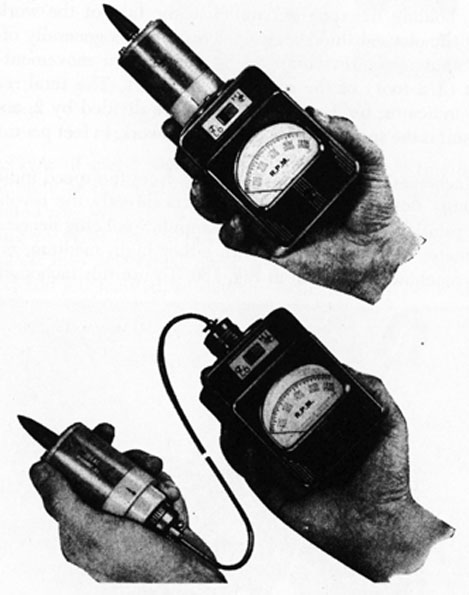
A self-energized electric tachometer, as shown in Fig. 181, is sometimes used aboard ship.
FIG. 181. ELECTRIC TACHOMETER.
194. Sounding Rods and Tapes.--One of the most common measurements taken aboard ship is that of sounding the tanks, as a check of the available quantity of water, fuel oil, lubricating oil, etc., must be made often. There are various devices, to be described in another lesson, which permit the amount of liquid in each tank of a ship to be measured hydraulically and to
193
be read from a gage located in a convenient position. Not all ships are so equipped, however, and there are many occasions when it is necessary to sound a tank, measuring the depth of liquid in it by means of a sounding rod or tape.
If the tank is not too deep, a metal rod, graduated in inches, and with a line fastened to its upper end, may be lowered through the sounding pipe until it reaches the bottom of the tank. If the liquid is fuel oil, the depth of oil in the tank is shown on the rod when it is withdrawn from the tank. If water is contained in the tank, the rod should be coated with chalk before being lowered, as this will enable the depth of water to be seen more readily on the rod. Even though the tank is an oil tank, it is often advisable to chalk the lower portion of the rod, as this may help to detect any water that is present, the water having settled to the bottom of the tank. In such a case, when the sounding rod is removed from the tank, small bubbles would be observed on the portion of the rod that extended into the water.
Chalking of the sounding rod is especially important when checking the measurement of an empty or nearly empty double-bottom tank, or any other fuel tank that could possibly leak and admit sea water. A most essential time for this to be done is when the tanks are sounded before taking on fuel supplies. The sounding rod should be scrutinized carefully for water, and if its presence is detected, it may very well indicate that a leak has developed in the tank since the last measurement was taken. If the leaky tank were to be filled with fuel, the fuel would become contaminated and within a short time would possibly be unusable and a total loss. A congealing condition might also result that would make the removal of the contaminated oil very difficult and expensive.
It is recommended that the sounding rod, or other arrangement lowered into a sounding pipe, be made of brass or bronze rather than of iron or steel. The iron or steel might cause a dangerous spark when dropped into an empty fuel tank.
In the ullage method of measuring the depth of liquid in a tank, a cup-shaped weight is lowered until the weight comes into contact with the surface of the liquid. A measurement is then taken which gives the distance from the surface of the liquid to the upper end of the sounding pipe. The total distance from the bottom of the tank to the upper end of the sounding pipe being known, it is only necessary to subtract the measurement from the total distance in order to find the depth of liquid in the tank. This method
194
has the advantage that the sounding apparatus does not become so smeared with oil as would be the case when lowered to the bottom of an oil tank.
The measurements taken with the equipment just described are usually in inches. In order to determine the quantity of liquid in gallons or barrels, it is necessary to consult a conversion chart for the tank in question.
195. Torsion Meter.-The torsion meter is an instrument used for determining the shaft horsepower being transmitted by a revolving shaft, such as the line shaft of a turbine-propelled vessel. The torsion meter measures the torsion, or twist, of the shaft under operating conditions, and this measurement, in conjunction with the known stiffness of the material of which the shaft is made, and the rpm of the shaft, enables the horsepower to be computed.
The torsion meter is usually used during the trial trip of a vessel and is then removed. It is not ordinarily a part of the permanent installation of the ship. The instrument may be designed to measure the torque by mechanical means, and there are also electric torsion meters.
195
ENGINE-ROOM TOOLS, PART 3
EXAMINATION QUESTIONS
Instructions : -Study the lesson very carefully before considering the examination questions. Then read each question slowly and be sure that you understand it. When answering the questions, always take sufficient time, prepare the answers in your own words, and do your best work. In arranging your answers, please leave space between them so that the instructor will be able to write in helpful explanation, should you make an error or overlook an important point. After the answers are completed, check them again very carefully; make sure that all questions are taken care of; correct each error that you find; and mail your work to us.
1. What is the measurement of the rectangular piece of stock, Fig. 134?
2. What type of rule can be used to measure:
(a) the outside diameter of a shaft?
(b) the depth of a piston ring groove?
3. It is desired to cut a piece of sheet metal so that a tube 20 inches long and approximately 2 7/8 inches in diameter can be constructed. The edges of the metal are to overlap 1/2 inch. Explain how the necessary width of material can be determined without calculation or reference to Tables.
4. When preparing to locate the exact point for drilling a hole in a piece of metal, it is often helpful to coat the area with chalk. Explain why.
5. Explain how to set a pair of dividers to lay out a 4-inch circle.
6. (a) Explain, in detail, how to line up a coupling.
(b) Explain the care to be given a feeler gage when not in use.
196
7. Explain why a sounding rod is coated with chalk, especially when sounding fuel oil double-bottom tanks prior to taking on fuel.
8. What danger may arise from the use of an iron or steel sounding rod?
9. What is the range of a 3-inch micrometer?
10. What is the purpose of a ratchet stop on a micrometer? How does it function?
11. What type of micrometer would be used to measure the thickness of a bearing insert?
12. Explain in detail how a micrometer of the type shown in Fig. 174 would be used to measure the exact diameter of a cylinder which has a diameter slightly less than 14 inches.
13. A 2-inch outside micrometer has been opened 32 turns when the measurement of the thickness of a piece of metal is taken. How thick is the metal? Explain.
14. When the thimble of a micrometer has been turned sufficiently to uncover exactly 8 graduations on the revolution line of the barrel, what distance has the spindle moved?
15. What is the measurement indicated by the micrometer reading at the left, Fig. 172?
16. What is the measurement indicated by the micrometer reading at the right, Fig. 172?
17. What is the measurement indicated by the lower micrometer reading, Fig. 176?
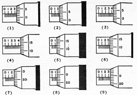
18. Give the measurements indicated by each of the 9 examples shown in Fig. 182. A 1-inch micrometer is used in each instance. Number your answers in accordance with the illustration.
197
FIG. 184.
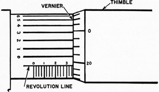
19. What measurement is indicated by the 1-inch vernier micrometer, Fig. 183?
FIG. 183.
198
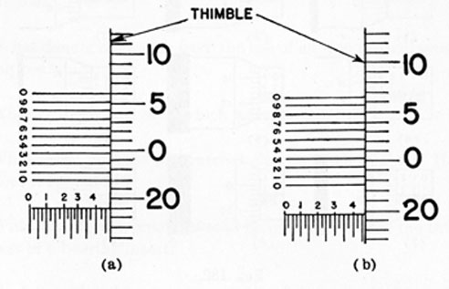
20. Give the measurements indicated by views (a) and (b) of Fig. 184. This is a 1-inch micrometer.