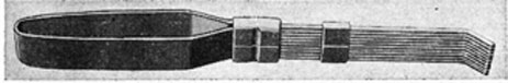
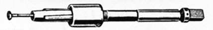
91. Machine Screws.-The term "machine screw" is generally used to designate the small screws that are used in tapped holes for the assembly of metal parts. The types of machine screws that are ordinarily encountered are shown in Fig. 78. Most of these screws are made of steel or brass, some being plated to resist corrosion. They are also made of stainless steel.
FIG. 78. MACHINE SCREWS.
88
There is a great variety of diameters, lengths, and head shapes manufactured. The thread diameter, length in inches, head shape, material from which made, and the type of finish, must therefore be included in a complete description of a machine screw.
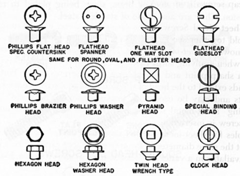
Occasionally machine screws with specially shaped heads, as shown in Fig. 79, are used aboard ship. Most of these screws require special tools for driving and removing. In some cases the tools are included in a kit that comes with the machine on which the screws are used.
FIG. 79. SPECIAL MACHINE SCREWS.
Machine screws are driven and removed with a screwdriver or wrench, depending on the type of screw head. Hexagon, or hex, heads are turned with socket wrenches; slotted heads are turned with plain screwdrivers; socket heads require an Allen-type wrench; and Phillips heads require special Phillips screwdrivers. Holes for fillister-head screws must be counterbored so that the head of the screw is flush with or below the surface.
92. Cap Screws.-Cap screws, sometimes called "tap bolts," perform the same functions as machine screws. They are generally used without nuts and are screwed into tapped holes. Their sizes range up to 1 inch in diameter and 6 inches in length.
Cap screws may have square, hex, flat, button, or fillister heads, as illustrated in Fig. 78. Fillister heads are best for use on moving
89
parts because such heads are sunk into counterbored holes. Hex heads are usually used where the metal parts do not move.
The strongest cap screws are made of alloy steel. Cap screws made of stainless steel are often specified on machinery exposed to salt water, which would soon corrode and "freeze" the threads of ordinary steel screws.
Some cap screws have small holes through their heads. A length of wire, called a safety wire, is passed through the holes in all of the screws in a group and is fastened at the ends, thus preventing the cap screws from coming loose.
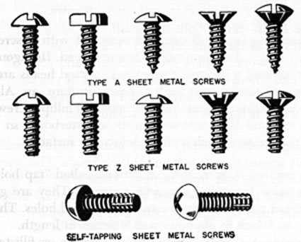
93. Sheet-Metal Screws.-The screws shown in Fig. 80 are used to hold together sections of sheet metal, fiber, plastic, etc., and are known as sheet-metal screws. They are especially useful aboard ship when applying sheet-metal covering over insulation. Type A has a sharp point and resembles a wood screw, except that the threads extend to the head of the screw. Type Z screws have blunt points and may be used with heavier material. A special "self-tapping" sheet-metal screw has a tap end that cuts threads as the screw is inserted.
Holes for sheet-metal screws should be drilled or punched to about the same diameter as the core of the screw used. The screws are available in a variety of head shapes, as shown in the illustration.
FIG. 80. SHEET METAL SCREWS.
90
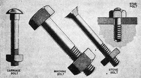
FIG. 81. COMMON TYPES OF BOLTS.
94. Machine Bolts.-Machine bolts, Fig. 81, are made in a variety of diameters, lengths, thread pitches, and head shapes. They are furnished in three grades: machine finished, semi-finished, and rough. Diameters range from 3/16 inch to 3/4 inch, and lengths from 1/2 inch to 30 inches. The larger bolts are usually made up to fit as needed instead of carrying them in stock.
Machine bolts are used to hold together frames and structures, particularly those which must be easily dismantled. Some bolts have holes drilled near the end of. the threaded part for cotter pins or safety wire. The nuts used on machine bolts may be either square or hexagonal, and the bolt heads also may be of either type. Washers are usually used with these bolts.
95. Stove Bolts.-Stove bolts are small, and were developed for use on stoves, as the name suggests. They can be used for many other jobs, however, where great accuracy and strength are not required and where there is no great amount of vibration to shake the nuts loose. Stove bolts have special coarse threads which make a free fit with the threads of the square nuts used on them.
96. Carriage Bolts.-Carriage bolts usually have round heads, with short square shanks just under their heads. This square portion prevents the bolt from turning. Their chief use is in wood structures, but they may be used with metal. Square nuts and flat washers are used on carriage bolts and are supplied with them.
97. Studs.-Studs, or stud bolts, have both ends threaded, but one end takes a nut while the other is screwed into a tapped hole.
91
The use of a stud is really a safety precaution, because the nut may still be removed, even if the end that is screwed into the casting is "frozen." Because studs are commonly used in castings, they generally have coarse threads.
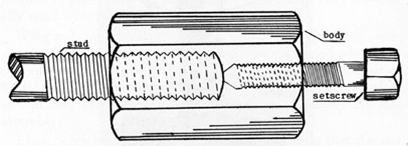
98. Stud Driver.-A stud driver, Fig. 82, is used to screw studs into place or to remove them without damaging the threads. It is also very useful when working on studs in inaccessible places. The driver consists of a square or hexagonal piece of steel or other metal which has one end drilled and tapped to receive the stud and the other end drilled and tapped for a setscrew.
FIG. 82. STUD DRIVER.
If the stud is to be installed in a hole, the stud should be screwed into the driver, and the setscrew tightened firmly against the stud. However, if the stud is already started in the hole, screw the driver on the stud and tighten the setscrew. In both of these operations the stud and stud driver are locked together, and a wrench is then used on the body of the driver to turn the stud.
If a stud driver is not handy when needed, a substitute can be made by screwing 2 nuts on the stud, and locking them together by applying a separate wrench to each nut. To unscrew the stud, a wrench should be applied to the inside nut. If the stud is being tightened, a wrench is applied to the outside nut.
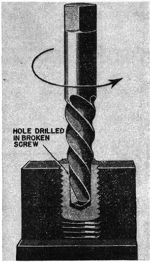
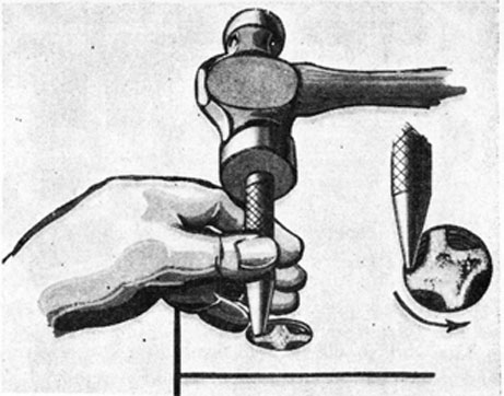
99. Screw Extractor.-At times a screw or stud will break off in a hole and must be extracted. The best method of doing this is to use a screw extractor, or "easy out." First drill a hole in the broken screw or stud a little smaller than its body diameter, so that the thread will not be damaged. Then insert the extractor in the drilled hole, tapping it lightly. (Extractors are marked with the size drill
92
with which they are to be used.) The screw extractor is tapered and has sharp ridges, and when a wrench is applied and the extractor turned counterclockwise, the ridges will grip the broken part so that it can be screwed out of the hole. A screw extractor inserted in a broken stud is shown in Fig. 83.
FIG. 83. USE OF SCREW EXTRACTOR.
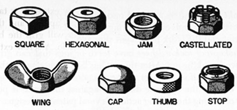
100. Nuts.-Several kinds of nuts are shown in Fig. 84. These must always be used with some kind of bolt or stud, so that the two pieces, nut and bolt or nut and stud, exert holding force by the strength of their threads. The combination is suited to assemblies that may have to be removed or taken apart.
Square and hexagonal nuts are standard, but they are supplemented by special nuts. One of these is the jam nut, or locknut, used above a standard hex nut to lock it in position. It is about half as thick as the standard nut, and has a washer face.
Castellated nuts are slotted so that a cotter pin may be pushed
93
FIG. 84. NUTS.
through the slots and a hole in the bolt. This provides a positive method of preventing the nut from working loose. They are usually used with machine bolts.
Wing nuts are especially useful where there is frequent occasion for hand adjustment. Cap or acorn nuts are used where appearance is an important consideration. They are usually made of brass, which is then chromium-plated. Thumb nuts are knurled, so that they may be turned by hand for easy assembly and disassembly.
Elastic stop nuts are used where it is imperative that the nut does not come loose. These nuts have a fiber or composition washer built into them. When the nut is tightened, the washer is compressed automatically against the screw threads to provide holding tension.
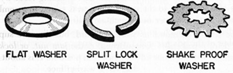
101. Washers.-Washers are often placed under nuts or bolt heads to protect the pieces being fastened or to make tightening up easier. Three kinds of washers are shown in Fig. 85.
Flat washers are used to back up bolt heads and nuts and provide larger bearing surfaces. They also prevent damage to the surfaces of the metal parts through which a bolt passes.
FIG. 85. WASHERS.
94
Split lock washers are used under nuts to prevent loosening by vibration. The ends of these spring-hardened washers dig into both the nut and the work to prevent slippage.
Shakeproof lock washers have teeth or lugs that can grip both the work and the nut. After the nut has been tightened on this type of washer, half of the lugs are bent against the nut and the other half bent in the opposite direction against the work, if possible, thus obtaining the locking action. Several patented designs, shapes and sizes are obtainable.
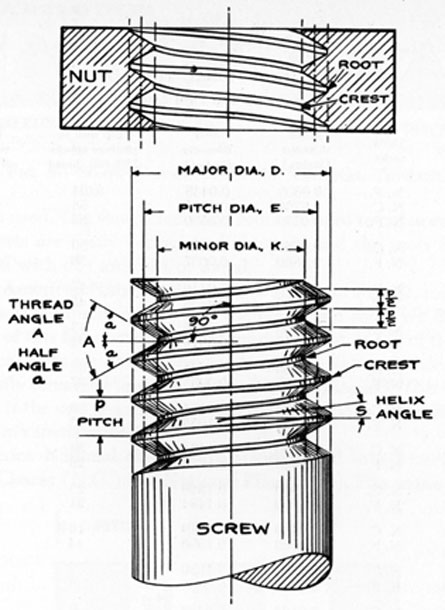
102. Threads.-Threads are helical ridges cut into screws, nuts, bolts, or in the walls of a hole, so that the action of turning gives an endwise as well as a rotary motion. A thread is either an outside (male) thread, or an inside (female) thread.
An understanding of the terms used in connection with screw threads is extremely important. The following definitions are therefore given, and refer to Fig. 86.
Angle of thread. The angle of thread is the angle included between the sides of the thread, measured in an axial plane.
Half angle of thread. The angle included between a side of the thread and the normal (90° from the axis), measured in an axial plane.
Lead. The distance a screw thread advances axially in one turn.
Major diameter. The largest diameter of the thread of the screw or nut.
Minor diameter, or root diameter. The smallest diameter of the thread of the screw or nut.
Pitch diameter. On a straight screw thread, the diameter of an imaginary cylinder, the surface of which would pass through the threads at such points as to make equal the width of the threads and the width of the spaces cut by the surface of the cylinder.
Pitch. The pitch of a thread is the measured distance from the crest of one thread to the crest of the next adjacent thread. The number of threads per inch, such as 8, 10, 12, etc., is equal to 1 divided by the pitch, in inches. The diameter and the pitch (or number of threads per inch) must be known in specifying or cutting threads.
103. Threads having major diameters of less than 1/4 inch are used on machine screws. The diameters range from 0.060 inch for
95
FIG. 86. SCREW THREAD TERMS.
size "0," to 0.216 inch for size 12, and vary 0.013 inch from one size to the next.
Threads having major diameters of 1/4 inch to 5/8 inch vary in diameter by 1/16 inch from size to the next. Threads with diameters of 5/8 inch to 1 1/4 inches vary in diameter by 1/8 inch. Table I includes data concerning standard threads up to 1 1/4 inches in diameter.
104. Thread Forms.-The four most common types of screw threads are the V-thread, the American National thread, the Square thread, and the Acme thread. The same rules for diameter and pitch apply to all types of threads.
The sharp V-thread, Fig. 87, has serious disadvantages and is
96
TABLE I.
AMERICAN NATIONAL THREADS
(Thread and Tap Drill Sizes)
Size and Threads per inch
Thr'd series
Major diameter (inches)
Root diameter (inches)
Tap drill to produce approx. 75% full thread
Decimal equivalent of tap drill
0-80
N. F.
0.0600
0.0438
3/64
0.0469
64
N. C.
0.0730
0.0527
53
0.0595
72
N. F.
0.0730
0.0550
53
0.0595
2-56
N. C.
0.0860
0.0628
50
0.0700
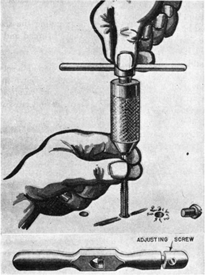
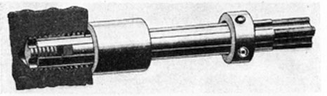
64
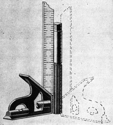
N. F.
0.0860
0.0657
50
0.0700
3-48
N. C.
0.0990
0.0719
47
0.0785
56
N. F.
0.0990
0.0758
45
0.0820
4-40
N. C.
0.1120
0.0795
43
0.0890
48
N. F.
0.1120
0.0849
42
0.0935
5-40
N. C.
0.1250
0.0925
38
0.1015
44
N. F.
0.1250
0.0955
37
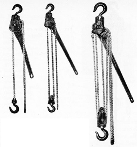
0.1040
6-32
N. C.
0.1380
0.0974
36
0.1065
40
N. F.
0.1380
0.1055
33
0.1130
8-32
N. C.
0.1640
0.1234
29
0.1360
36
N. F.
0.1640
0.1279
29
0.1360
10-24
N. C.
0.1900
0.1359
25
0.1495
32
N. F.
0.1900
0.1494
21
0.1590
12-24
N.C.
0.2160
0.1619
16
0.1770
28
N. F.
0.2160
0.1696
14
0.1820
1/4-20
N. C.
0.2500
0.1850
7
0.2010
28
N. F.
0.2500
0.2036
3
0.2130
5/16-18
N. C.
0.3125
0.2403
F
0.2570
24
N. F.
0.3125
0.2584
I
0.2720
3/8-16
N. C.
0.3750
0.2938
5/16
0.3125
24
N. F.
0.3750
0.3209
Q
0.3320
7/16-14
N. C.
0.4375
0.3447
U
0.3680
20
N. F.
0.4375
0.3726
25/64
0.3906
1/2-13
N. C.
0.5000
0.4001
27/64
0.4219
20
N. F.
0.5000
0.4351
29/64
0.4531
9/16-12
N. C.
0.5625
0.4542
31/64
0.4844
18
N. F.
0.5625
0.4903
33/64
0.5156
5/8-11
N. C.
0.6250
0.5069
17/32
0.5312
18
N. F.
0.6250
0.5528
37/64
0.5781
3/4-10
N. C.
0.7500
0.6201
21/32
0.6562
16
N. F.
0.7500
0.6688
11/16
0.6875
7/8-9
N. C.
0.8750
0.7307
49/64
0.7656
14
N. F.
0.8750
0.7822
13/16
0.8125
1-8
N. C.
1.0090
0.8376
7/8
0.8750
14
N. F.
1.0000
0.9072
15/16
0.9375
97
FIG. 87. SHARP V AND AMERICAN NATIONAL THREADS.
seldom used. The sharp crests and roots are hard to cut accurately; the crests are easily dented and chipped; and the roots become clogged with dirt and bits of metal.
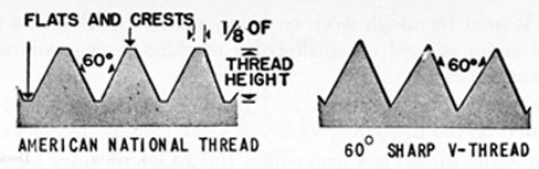
The American National thread, also shown in Fig. 87, resembles the sharp V-thread, except that the crests and roots are flat. The length of this flat portion, of both crest and root, is 1/8 of the pitch distance. Because of the design, American National threads are not easily damaged and the roots are easily cleaned. This type of thread is the one generally used on the many bolts and nuts found in a ship's installation.
America National threads are standardized into 2 series, National Coarse (N.C.) and National Fine (N.F.). The coarse thread
Fig. 88. SQUARE AND ACME THREADS.
98
series is used for rough work on heavy materials, while the fine thread series is used on small bolts, machine screws, adjusting mechanisms, etc.
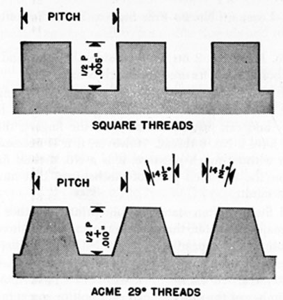
The Square thread, shown in Fig. 88, is strong and efficient. It is used on the tightening screws of vises, clamps, and jacks.
The Acme thread is a heavy-duty thread whose sides form an angle of 29 degrees with each other. This type of thread can withstand heavy strains and loads, and is easier to machine than Square threads.
105. Most threads are right-hand threads, that is, they advance when turned clockwise. Left-hand threads, however, are required by some machines and installations. They advance when turned counterclockwise. Left-hand threads are often labeled so that they will not be turned the wrong way. Right-hand taps and dies cannot be used to cut left-hand threads; a special left-hand tap and die is necessary.
106. The fit of threads depends on the clearance between the threads of mating parts, the four different fits being as follows:
The No. 1 and No. 2 fits have considerable play and are used on stove bolts and bolts used for rough construction.
The No. 3 fit is the one specified for machine parts, engine bolts and most threaded parts. If a matching bolt and nut have very little play and can just be turned with the fingers, the threads probably have a No. 3 thread. However, if it is necessary to use a wrench without much pressure, it is a No. 4 close fit. This fit is used for the threaded parts of mechanisms that must be extremely accurate.
Thread fits are often stated on blueprints, together with the thread's major diameter, the threads per inch, and thread series. Such a note would appear as -3/8-16 N.C.-3. The first number indicates the diameter, in inches; the second number, the number of threads per inch; and the last number, the thread fit.
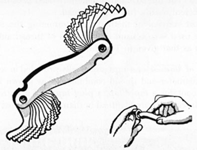
The number of threads per inch of a bolt or screw may be determined by using a screw pitch gage, shown in Fig. 89. This gage
99
FIG. 89. SCREW PITCH GAGE.
has a number of pivoted, knife-like blades whose edges are cut to represent the various thread pitches. To use the gage, select and try the blades in turn until one fits the thread exactly, then read the number stamped on that blade.
107. Taps and Dies.-Taps and dies are tools used for cutting screw threads. Taps are used to cut inside threads and dies to cut outside threads.
Taps and dies can be classified under the following headings: 1. Type of thread formed, such as N.F. or N.C.; 2. Diameter of the screw formed or hole tapped; 3. Number of threads per inch.
The two kinds of taps in common use are known as standard hand taps and machine screw taps. Standard hand taps are made for cutting threads from 1/16 inch up to 4 inches in diameter; machine screw tap diameters are designated by numbers ranging from No. 0 (smallest) to No. 30 (largest) to fit the corresponding sizes of machine screws.
In order that there may be enough metal in the hole to provide material into which the threads can be cut, the hole must be drilled smaller than the major diameter of the tap threads. The size of the drill to be used can be computed by taking 75% of the difference between the major and minor diameters, and subtract this amount from the major diameter. The resultant thread is
100
known as a "75% thread," and is generally used because it is only 5% less efficient than a full depth thread.
The most convenient method of determining the size of tap drill to be used is to consult a tabulation of thread and tap drill sizes such as that given in Table I.
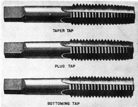
108. Sets of taps.-Hand taps are usually provided in sets of three for each diameter and thread combination, as shown in Fig. 90. Each set contains a taper tap, a plug tap, and a bottoming tap. The taps in each set are identical in diameter and cross section.
FIG. 90. TAPS.
The taper tap may be used for internal threading where the work permits the tap to be run entirely through. When the taper tap cannot be run through the work, the diameter will be so small near the bottom of the tapped hole that the screw or bolt will not screw down as far as it should. In this case a plug tap is used after the taper tap is removed. If full diameter threads are desired all the way to the bottom of the hole, the plug tap is followed by a bottoming tap, which is the same diameter its entire length.
109. Use of Taps.-Taps are held in tap wrenches while they are being used. There are two types of wrenches, the T-handle for small taps and restricted spaces, and the adjustable tap wrench for general use and larger taps. Examples of tap wrenches are shown in Fig. 91.
101
FIG. 91. TAP WRENCHES.
When starting to tap a hole, secure the work in a vise, if possible. The best arrangement is one in which the tap can be operated in the vertical position. It is also very important to start the tap straight and keep it so throughout the work, because taps, especially small ones, will break if bent or strained. After a tap starts to cut, it is not fed into the hole with much pressure, as its threads will tend to pull it in at the proper rate. Also, a tap should not be turned continuously. The best method is to turn it forward about 1/4 turn, and then turn it back until the chips break loose, before continuing to turn it forward. This process should be repeated for each 1/4 turn forward.
Taps work better if they are kept cool. When tapping steel or bronze, the tap should be well lubricated, preferably with lard oil. The oil also helps the chips to flow out of the hole and from the flutes of the tap.
102
Cast iron is drilled, tapped, and reamed dry. Soft metals, such as brass, can also be tapped dry.
It should be noted that some small taps, up to the 3/8-inch size, have large shanks which should not be turned beyond the surface of the work being tapped, as these shanks exert a reaming action which would cut out the threads.
110. Removal of Broken Tap.-Taps will sometimes break off, even when used with care. There are two ways of satisfactorily removing the broken part of a tap from a hole: (1) by means of a tap extractor; (2) by using a chisel or punch.
A tap extractor having 4 "fingers" that slip along the flutes of the tap is shown in Fig. 92. This tool is turned with a wrench, which must be used carefully to prevent damage to the long thin fingers of the extractor.
FIG. 92. USE OF TAP EXTRACTOR.
Broken taps can often be removed by using a blunt cold chisel or a taper punch, as shown in Fig. 93. If done carefully, this will frequently start the tap. The job can then be completed with a tap extractor as previously described. Taps often shatter when they break; the broken pieces should be picked from the hole with a small prick punch or a magnetized scriber before any attempt is made to remove the tap. Removing a broken tap by any method is often a long, tedious job which requires time, skill, and patience. It is therefore wise to avoid breakage by being as careful as possible.
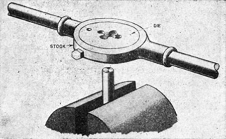
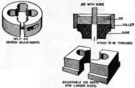
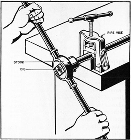
111. Cutting Outside Threads.-Outside threads are usually cut by the use of some type of die held in a die stock for turning leverage. The complete assembly of a stock and solid die is shown in Fig. 94. Solid dies are not adjustable.
Round dies similar to the one shown in Fig. 94, but with an adjustable slot, are usually found aboard ship. By adjusting the
103
FIG. 93. REMOVING BROKEN TAP WITH PUNCH.
width of the split or slot, the diameter and fit of the thread can be controlled. Some of the dies are equipped with guides, which help to start the cut and keep the threads straight.
Dies for larger diameters are made in two parts, and are removable, replaceable, and adjustable. The two parts slide in a groove and are adjusted with a screw. Two types of adjustable dies are shown in Fig. 95.
The procedure for using dies correctly is similar to that for
FIG. 94. STOCK AND DIE.
104
FIG. 95. ADJUSTABLE DIES.
tapping. The work should be held firmly in a vise, and any burr on the end of the piece to be threaded should be removed. The die will start the cut more readily if the end of the piece of material is chamfered slightly to provide a starting place for the die. The chamfer can be cut with a file or a grinder. To start the thread, place the large side of the opening in the die over the work and press down firmly on the stock. Die threads are tapered from one face only, so be sure to start the cut with that face. Reverse the die only when it is necessary to cut full threads up to a square shoulder. When cutting the thread, turn the die forward for part of a revolution and then turn it back slightly so as to release the chips before making the next forward turn.
It is usually best to adjust the die to cut oversize threads at first, as threads can always be made smaller, but cannot be made larger. Examine the finished threads for imperfections. Each thread should be a full thread.
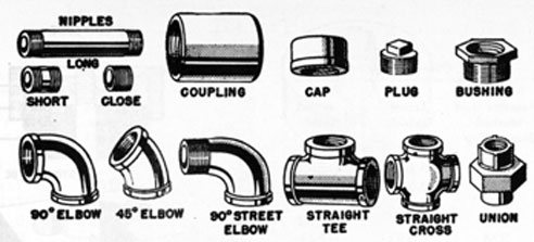
112. Pipe Fittings.-Aboard ship it is often necessary to cut, thread, bend and fit together various lengths of pipes. It is therefore important to be thoroughly familiar with the commonly used fittings, examples of which are shown in Fig. 96.
Pipes up to 2 inches in diameter are usually joined with pipe fittings. The pipe fittings are tapped and threaded with pipe threads, which taper 3/4 inch per foot of thread. Larger pipe is usually joined either by bolted flanges or by welding. Additional information concerning pipe fittings will be found in Marine Pipe-fitting.
105
FIG. 96. PIPE FITTINGS.
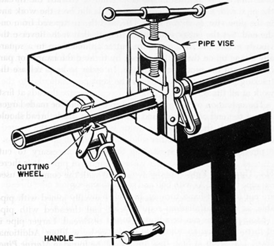
113. Cutting Pipe.-Pipe can be cut with a hacksaw, but a pipe cutter is more satisfactory and should be used, if available. The use of a pipe cutter and pipe vise is shown in Fig. 97. The cutter has a special alloy steel cutting wheel and two pressure rollers.
When measuring pipe it is necessary to allow sufficient length for thread to enter each fitting. The amount to be allowed for the thread depends on the nominal diameter, or size, of the pipe,
FIG. 97. PIPE CUTTER AND PIPE VISE.
106
TABLE II.
Pipe Diameter, Inches
Nominal Diameter and Marked Size of Tap
Actual Outside
Actual Inside
Threads per Inch
Size of Tap Drill (Reamer not used)
Length Allowed for Thread, Each Fitting Inches
1/8
0.405
0.269
27
R
5/16
1/4
0.540
0.364
18
7/16
7/16
3/8
0.675
0.493
18
37/64
7/16
1/2
0.840
0.622
14
23/32
9/16
3/4
1.050
0.824
14
59/64
9/16
1
1.315
1.049
11 1/2
1 5/32
11/16
1 1/4
1.660
1.380
11 1/2
1 1/2
11/16
1 1/2
1.900
1.610
11 1/2
1 47/64
11/16
2
2.375
2.067
11 1/2
2 7/32
3/4
2 1/2
2.875
2.469
8
2 41/64
1 1/16
3
3.500
3.068
8
3 1/4
1 1/8
3 1/2
4.000
3.548
8
3 3/4
1 3/16
4
4.500
4.026
8
4 1/4
1 3/16
5
5.563
5.047
8
5 5/16
1 5/16
6
6.625
6.065
8
6 23/64
and is given in Table II. When the correct measurement has been determined, the location of the cut should be marked clearly on the pipe with a file or scriber. The pipe should be secured firmly in the pipe vise, as shown in Fig. 97, and the cutter slipped over the end. Set the cutter with the cutting wheel on the mark previously made, and then rotate the cutter around the pipe, gradually taking up on the cutting wheel, by turning the handle of the cutter, until the pipe is cut through. In order to keep the wheel tracking properly, the cutter must be kept perpendicular to the work at all times.
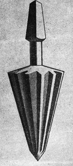
The operation of the pipe cutter leaves a shoulder on the outside of the end of the pipe and a burr on the inside. Always remove both. If the burr on the inside is not removed, the ragged edges will catch dirt and other solid matter and will block the flow. A pipe reamer, Fig. 98, is used for the purpose.
114. Threading Pipe.-Special dies, called pipe dies, are used to
cut pipe threads. As with bolt and screw threads, most pipe threads are cut for right-hand turning, but left-hand pipe dies are available, as some installations require a left-hand thread.
Most pipe dies can be adjusted to cut slightly different depths of threads. When an adjustable die is used, the thread is cut to about 1/2 depth at first, then the die is readjusted to finish cutting the thread to the full depth.
107
FIG. 98. PIPE REAMER.
To cut a pipe thread, secure the pipe in a pipe vise, and place the stock and die on it as indicated in Fig. 99, This type of die has a guide clamp, as shown in the illustration. The clamp fits over the pipe and is tightened in position with a screw. As the die stock is revolved, the clamp draws the die on the pipe, the die cutting the thread as it is turned. The clamp also helps to keep the threads straight.
The number of threads cut should not be greater than the number of threads of the die, and the cut is complete when the end of the pipe is flush with the back surface of the die. The work should be backed up frequently as with the other forms of thread cutting, so as to clear the chips. Oil should be used freely during the thread cutting process.
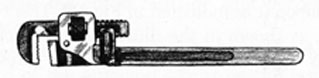
115. Pipe Wrenches.-Threaded joints should be screwed together by hand and then tightened with a pipe wrench, often
108
FIG. 99. THREADING PIPE.
called a "Stinson." The pipe should be held in a pipe vise during assembly, if possible, but if it is not feasible to use a vise, the pipe may be held with another pipe wrench. A pipe wrench is shown in Fig. 100.
FIG. 100. PIPE WRENCH.
The pipe wrench is designed for use on pipe and screwed end fittings only and should never be used on hexagon or square nuts. The jaws of the pipe wrench exert a squeezing action, and the teeth of the jaws tend to cut into the metal that is gripped. The harder the wrench is pulled, the tighter it squeezes, and this squeezing action can do great damage. Many inexperienced men have learned that a pipe wrench can scar or crush a pipe fitting or other piece of equipment. It is never advisable to grip the open end of a piece of pipe or a fitting with a pipe wrench without first protecting the end of the pipe with a fitting, or the fitting with
109
FIG. 101. DIRECTION OF PULL ON PIPE WRENCH.
a piece of pipe. This strengthens the work and enables it to withstand the stress impressed by the wrench.
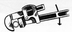
No instructions are necessary on which way to pull on a pipe wrench because it works only in one direction, as shown in Fig. 101. The pipe wrench will be found to function best when the bite is taken midway of the jaw teeth, and when the size of the wrench is properly chosen for the job. Jaw teeth should be kept clean and sharp, and the springs should be kept in good operating condition to allow quick one-hand grip and release. A few drops of oil applied to the adjusting nut will help to keep the wrench in good working order.
Pipe wrenches are made in sizes ranging from 6 to 48 inches. The correct wrench sizes for use with various sizes of pipe are given in the following:
Pipe Wrench Size (inches)
Pipe Size (inches)
6
1/4
10
3/8 and 1/2
14
3/4
18
1 and 1 1/4
24
1 1/2 and 2
36 and 48
2 1/2 and up
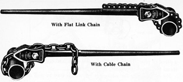
116. Chain Pipe Wrenches.-Chain pipe wrenches, also known as "chain tongs," are wrenches of the chain strap and lever type. Two examples of this wrench are shown in Fig. 102. They are generally designed for use on large diameter piping, although they are also made in sizes suitable for handling small pipe.
When using this type of wrench, the best gripping position is midway on the jaw teeth. The wrench is also designed so that the handle will bend under a heavy load before the chain will break. The bending of the handle should therefore be taken as a warning that maximum load has been applied.
110
FIG. 102. CHAIN PIPE WRENCHES.
On the type of wrenches that have flat link chains, an occasional inspection should be made of the first two or three rivets and links adjacent to the anchor link, as the load is greatest at that point. Badly bowed or curved rivets indicate that the chain has been loaded almost to breaking strength and is probably unsafe. On cable-link chains the links give warning by stretching and pulling "rigid" if the breaking point is approached.
117. Rivets.-Rivets, although not threaded, are classified as metal fasteners, the pressure of their heads, instead of threads, exerting the holding force. Rivets are commonly used for permanent fastening and are not practical for any assembly that has to be taken apart. Rivet holes must be drilled or punched and must be carefully spaced and aligned. The thickness of the parts to be riveted and the load to be applied determine the proper diameter and length of the hole.
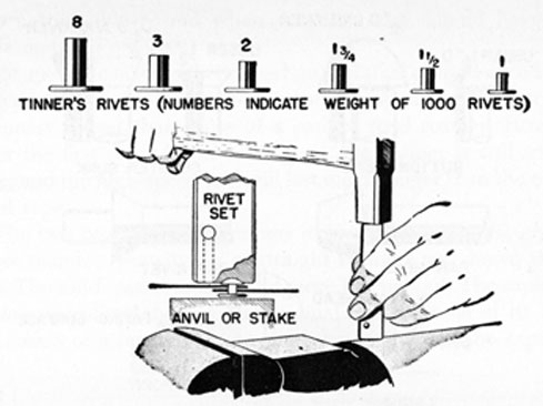
Tinner's rivets are used on thin metal sheets. They have flat heads, are made of soft iron or steel, and are usually coated with tin as a protection against corrosion. The weight, in lbs, of 1,000 rivets, denotes the size of rivets, as shown in Fig. 103. The length of a rivet is proportional to its weight and diameter.
The use of a rivet set is necessary with tinner's rivets. After the rivet has been inserted in the holes in the pieces of material being riveted together, the set is placed over the headless end of the rivet and is used to press the sheets of metal together and against the rivet head. The recessed hole for this purpose in the set is indicated by the broken lines in Fig. 103. The set is then removed
111
FIG. 103. TINNER'S RIVETS AND RIVET SET.
and the rivet is upset (headed upon the headless end) with a riveting hammer. After this is done, the set is used to round the upset end. Rivet sets are provided in several sizes.
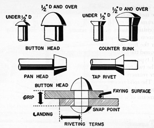
Structural rivets, shown in Fig. 104, may be used to fasten the plates of a tank or boiler and the structural members of a ship. They are used on many types of steel frameworks and structures, and are usually heated for driving. This causes the rivets to contract as they cool and helps to hold the riveted members tightly together. The rivets also drive easier when hot. Structural rivet diameters vary from 1/4 inch to 1 1/4 inches, but even larger sizes are used for thick sections. The length of a rivet should be approximately 1 1/2 times the diameter of the rivet, plus the grip (combined thickness of the riveted sheets).
The terms used in Fig. 104 should be noted. The landing, or distance from the center of the rivet to the edge of the material, should not be less than times the diameter of the rivet. The space between rivets should be from 3 to 8 diameters of the rivet used, measured from center-to-center.
While one end of a rivet is being hammered, the other end must be supported by an anvil or some other suitable means. The force of the blow should always be proportioned to suit the size of the rivet.
A rivet may be removed by cutting off the rivet head with a
112
FIG. 104. STRUCTURAL RIVETS.
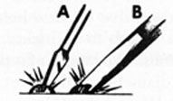
cold chisel and punching out the body of the rivet. In case of a large rivet, first cut a groove through the center of the rivet head, as shown in Fig. 105 (A). Then cut off the rivet head as shown in view (B). A small rivet is easy to remove if the head is drilled before the chisel is used. The hole should be drilled through the head only, and the weakened head then cut off with a chisel.
FIG. 105. CUTTING OFF RIVET.
118. Reamers.-A very slight variation in the nominal diameter of a drilled hole is of little importance in some cases, but where greater accuracy is required, the holes are reamed, that is, the hole is first drilled somewhat smaller than the exact desired diameter, and is then reamed out to the proper size with a reamer. The principal reason for the reamer being able to do better work than the drill is that it is not used to originate holes, and its action is, therefore, not dependent upon a somewhat uncertain guiding point. Other reasons are that it nearly always has more than
113
two cutting edges, and when properly used should have very little metal to remove.
Reamers are made either of carbon tool steel or high-speed steel. The cutting blades of a high-speed steel reamer lose their original keenness sooner than those of a carbon steel reamer. However, after the first super-keenness is gone, the reamer is still serviceable, and the high-speed tool will last much longer than the carbon steel type.
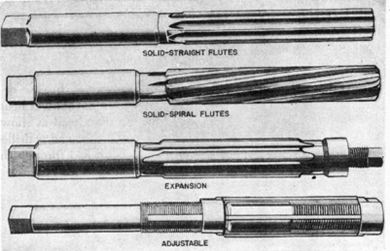
The two types of hand reamers in general use are straight and taper reamers. Four types of straight reamers are shown in Fig. 106. The solid reamer is one solid piece throughout. The expansion reamer is hollow and has longitudinal cuts in some of its flutes. By means of a tapered screw plug its diameter can be expanded
FIG. 106. TYPES OF STRAIGHT REAMERS.
a few thousandths of an inch. Both solid and expansion reamers are made with straight and spiral flutes, and the cutting edges or lands between the flutes are usually regularly spaced. However, some solid reamers have irregularly spaced lands to avoid "chatter," which causes roughness in the finish of the work.
The blades of the adjustable reamer are separate from the body and are fitted into grooves in the threaded shank of the tool. Adjusting nuts fit on these threads, and when the nuts are turned back and forth, the blades are moved along the tapered grooves,
114
thus increasing or decreasing the diameter of the reamer. It is advisable to use a solid reamer for most work because it is the most rugged and accurate of the straight reamers.
119. Use of Reamer.-Reamer blades are hardened to such an extent that they are brittle, so reamers should be handled carefully to prevent chipping the blades. Always rotate a reamer in the cutting direction.
Another important factor in the use of a straight hand reamer is to have the hole the correct size to begin with, and then to be sure that the reamer is started straight in the hole. One method of getting the reamer started straight, by checking it from side to side with a square, is shown in Fig. 107.
Straight reamers have a slight taper on 1/4 to 3/4 inch of the end, so that they will start into the hole easily. One form of reamer has a shallow screw thread at the entering end. This thread takes hold of the metal and draws down into the work.
FIG. 107. USING SQUARE TO START REAMER STRAIGHT.
115
A reamer is turned by means of a wrench, or it can be set up in a vise and the work turned around it. The reamer should be turned slowly until the operator is sure that it is straight in the hole, and then should be turned with a steady, firm pressure until it has been put all the way through the hole. The leading end is subjected to the greatest amount of wear because it does the greatest amount of work. If, therefore, only this leading end is put through, the hole will not be of a uniform diameter throughout.
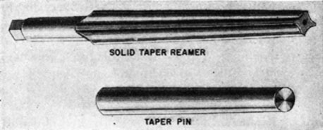
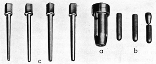
120. Taper Reamers.-Taper reamers are used to finish tapered holes for the insertion of tapered pins or other tapered parts. A solid taper reamer and taper pin are shown in Fig. 108.
FIG. 108. TAPER REAMER AND PIN.
Taper reamers are made with a standard taper of 1/4 inch per foot, the various sizes being arranged so that each overlaps the next size by about 1/2 inch, that is, a No. 8 taper reamer could be inserted about 1/2 inch into a hole that had been reamed with a No. 7 reamer.
When using taper reamers, it is very important that the drilled hole be the right size, generally just large enough to allow about 1/2 inch of the reamer's length to enter it. A table similar to Table III should be consulted for the correct size of drill and other pertinent dimensions. However, if such a table is not available, no choice remains except the "cut and try" method, taking extreme care not to ream the hole too large or too deep. When starting the taper reamer, always keep it as straight as possible.
121. Machine Reamers.-The machine reamer is usually inserted in a chuck or a socket mounted in the spindle of a portable electric
116
or air motor. Machine reamers are also made either solid or adjustable, and each of these groups may be subdivided into straight or taper reamers.
Machine reamers differ from hand reamers in that nearly all the cutting is done by the beveled ends of the teeth, which act as a series of single cutting tools, each taking a small part of the total cut. The hand reamer is constructed so that all of its cutting is done by the sides of the teeth. Machine reamers are often used where holes are to be finished to a fair degree of accuracy and with a fair finish, but when extreme accuracy and a fine finish is required, hand reamers are used.
For general use, an expansion type of machine reamer is the most practical. This type is furnished in standard sizes from 1/4 inch to 1 inch, increasing in diameter by 32nds. Each reamer has a maximum expansion of 1/32 inch, so a set covers any reaming job from 1/4 to 1 inch.
Internal hones are much like adjustable reamers. The principal difference is that hones have abrasive blades. Large hones are rotated by electric drills or special motors for such jobs as truing the walls of engine cylinders.
122. Care of Reamers.-As stated previously, a reamer must never be turned in any way except to the right, or clockwise, even when removing it from the work. Do not use too much feed (pressure) because the reamer may hit a hard spot in the metal and break. This is especially likely with small reamers. When using a lubricant on the reamer, it is good practice to remove the tool from the work frequently and wipe away the chips which stick to the flutes. If the chips should clog, they would be likely to damage the finish on the walls of the hole. Remember that an adjustable reamer must be kept absolutely clean to do accurate work. Handle reamers carefully; if they are dropped or thrown against other tools, their sharp edges will be nicked and dulled. If the hole is too small, enlarge it with a drill before reaming it.
123. Preventing Chatter in Reamers.-When a hand reamer chatters, even when fed with the proper pressure, it is generally a sign that it has not been sharpened correctly for the particular metal being reamed. When chattering occurs, replace the reamer being used with another one. If it is not replaced, the walls of the hole will be rough, and work and time will be wasted.
117
TABLE III.
Taper Reamers and Pins
Size No.
Dia. of Small End of Reamer (Inches)
Dia. of Large End of Reamer (Inches)
Length of Flute (Inches)
Total Length of Reamer (Inches)
Size Drill for Reamer (Inches)
Longest Limit Length of Pin (Inches)
Dia. of Large End of Pin (Inches)
Approx. Fractional Size at Large End of Pin (inches)
0
0.135
0.162
1 5/16
2
28
1
0.156
5/32
1
0.146
0.179
1 9/16
2 3/8
25
1 1/4
0.172
11/64
2
0.162
0.200
1 13/16
2 11/16
19
1 1/2
0.193
3/16
3
0.183
0.226
2 1/16
3
12
1 3/4
0.219
7/32
4
0.208
0.257
2 3/8
3 7/16
3
2
0.250
1/4
5
0.240
0.300
2 7/8
4 1/8
1/4
2 1/4
0.289
19/64
6
0.279
0.354
3 5/8
5
9/32
3 1/4
0.341
11/32
7
0.331
0.423
4 7/16
6 1/16
11/32
3 3/4
0.409
13/32
8
0.398
0.507
5 1/4
7 1/16
13/32
4 1/2
0.492
1/2
9
0.492
0.609
6 1/8
8 1/8
31/64
5 1/4
0.591
19/32
10
0.581
0.727
7
9 1/2
19/32
6
0.706
23/32
11
0.706
0.878
8 1/4
11 1/4
23/32
7 1/4
0.857
55/64
12
0.842
1.050
10
13 3/8
55/64
8 3/4
1.013
1 1/64
13
1.009
1.259
12
16
1 1/64
10 3/4
1.233
1 15/64
Taper equals 1/4 inch per foot or 0.0208 inch per inch.
These reamer sizes are so proportioned that each overlaps the size smaller about 1/2 inch.
118
Resharpening reamers is usually a factory operation; the average person should not attempt it, although sometimes, if the edges of the reamer are only slightly dull, they can be restored by using a fine stone on the flutes. If the reamer is adjustable, it may be possible to insert new blades in it.
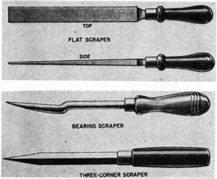
124. Scrapers.-Scrapers are made in many forms, the type to be used depending on the particular job to be done. Several commonly used types are shown in Fig. 109. Flat scrapers should be used for scraping or removing high spots from flat surfaces only; bearing scrapers are used for truing up bearing surfaces; and the 3-corner scraper is commonly used for removing burrs or sharp internal edges from soft bushings, etc.
FIG. 109. SCRAPERS.
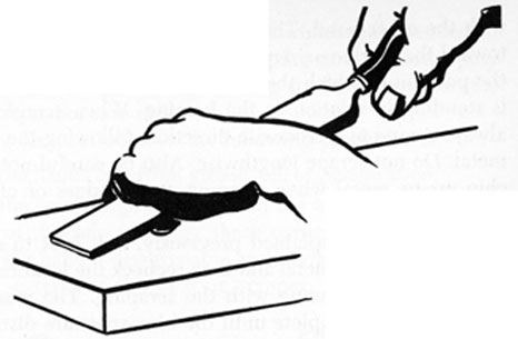
125. Flat scrapers.-To scrape a flat surface, select a scraper with the length and width suitable to the work. Use a fairly light pressure to hold the scraper against the work, although the harder the material being scraped the more pressure required. The right way to hold a flat scraper is shown in Fig. 110.
If there are holes in the work, avoid pushing the scraper across them; instead work around their sides. When scraping near the edge of a piece, scrape toward the edge, or at an angle to it. Do not scrape parallel to it.
119
FIG. 110. USING FLAT SCRAPER.
126. Scraping a Bearing.-It is often necessary aboard ship to refit a bearing. This operation must be done very carefully, as the metal of the bearing must be shaped so as to fit its pin or journal with the correct clearance and without high spots.
When it is believed that a bearing needs refitting, the bearing bolts are loosened and the bearing halves removed, the exact procedure depending on the construction. The bearing metal is examined, and if burnished or discolored spots are present, showing contact and heating of the bearing metal, these high spots must be removed.
Each bearing half is also tested by applying a thin coating of Prussian blue to the shaft and then placing a bearing half on the shaft and rotating it back and forth several times. When the bearing is removed from the shaft, the spots of blue on the bearing metal indicate the areas of contact. These high spots are removed by the process known as "scraping in," which means that a bearing scraper is used to scrape off the contacting areas, the bearing being retested and scraped in until uniform distribution of the blue spots indicates that the bearing bears evenly over the desired surface.
Since the scraping of a bearing usually involves the removal of a comparatively small quantity of soft bearing metal, and the cutting edges of the scraper are ground to a keen edge, only a light scraping pressure is needed. If too much pressure is applied, not only will too much metal be removed, but in addition the scraper will tend to "chatter" and leave a rough uneven surface.
When scraping a bearing, the handle of the scraper is held firmly with one hand and the blade of the scraper carefully guided
120
with the other hand. The scraper can be pushed away or pulled toward the workman, depending on the location of the high spot, the position in which the bearing is held, or where the workman is standing in relation to the bearing. When scraping, however, always scrape in a crosswise direction, following the curve of the metal. Do not scrape lengthwise. Also be careful not to gouge or chip excess metal when scraping at the edges of oil grooves or other openings.
In general, as explained previously, it is best to remove only a small amount of metal and then recheck the location of the high spots before continuing with the scraping. The work is usually not considered complete until the blue spots are distributed over a combined area equivalent to about 75 per cent of the total bearing surface.
Remember that scraping increases the running clearance of the bearing. If too much metal is removed, the clearance will be increased above the desired amount and this will necessitate the removal of shims to reduce the clearance. Removal of shims might possibly create a new series of high spots and the fitting and scraping would have to be done all over again.
127. 3-Corner Scrapers.-When using a 3-corner scraper, use the same motion as though .handling a bearing scraper. As a rule, the 3-corner scraper is used on material requiring fairly firm pressure, but only a small amount of metal should be removed at each stroke.
FIG. 111. CARBON SCRAPER.
128. Carbon Scrapers.-The carbon scraper, Fig. 111, is a tool commonly used for cleaning carbon deposits from cylinder heads, pistons, and chambers of small engines. This scraper has a dull edge to lessen the danger of scoring the piston or cylinder wall.
129. Care of Scrapers.-Keep scrapers (except the carbon scraper) sharp at all times, or they will not leave a smooth surface and will require more pressure than is necessary. The usual method
121
of sharpening is first to grind the tool on a wheel, and then to finish the operation on an oilstone. In scraping any surface, apply the pressure to the scraper on the cutting stroke only, otherwise the tool will soon become dull.
When using scrapers observe the following precautions:
(1) Keep the hands free from grease, oil, or perspiration.
(2) Keep the hands high enough from the work to avoid striking a corner of it while working; these corners are often sharp and can give the hand a disagreeable and perhaps dangerous cut. Be especially careful of the bearing scraper; its edges are very sharp.
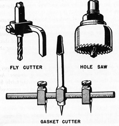
FIG. 112. GASKET CUTTER, FLY CUTTER, AND HOLE SAW.
130. Gasket Cutters.-A gasket cutter, Fig. 112, is used to cut round gaskets from sheets of gasket material, such as cork, rubber, leather, asbestos, composition, etc. The tool has two adjustable knives; one makes the inside hole, the other cuts the outside of the gasket. The sizes of the gaskets are therefore limited only by the size of the cutter available. When cutting a gasket, the material is spread out on a piece of wood, the outside and inside diameters of the gasket are determined, and the knives are adjusted at the correct position. With the shank of the tool held in a brace, the
122
pivot point is inserted through the gasket into the wood and the cutter rotated carefully until the knives cut through the gasket material.
To make bolt or stud holes in the gasket after it has been cut, mark their location accurately on the gasket, and then use a gasket punch to cut the holes.
The preparation of a gasket, especially for an irregularly shaped surface, can often be facilitated by holding the gasket material in place on the joint area and carefully tapping the outline of all openings with the ball peen of a machinist's hammer. If this is done skillfully, the edges of the stud holes and other apertures will cut the gasket to fit as the peening is carried out. Best results can usually be achieved by this method when the piece of material from which the gasket is made is only slightly larger than the joint. A larger piece of material might be bulky and inconvenient and tend to slip while being worked on, thus ruining the job. Try to use the gasket material, however, so that there is little waste.
131. Fly Cutters.-Fly cutters, Fig. 112, are designed to cut holes in sheets of soft metal, such as brass, aluminum, soft steel, etc. They may also be used to cut holes in sheets of fiber, bakelite, plastic, and similar materials. One type of fly cutter has one cutting bar and the other has two cutting bars. The tool is used in much the same way as a gasket cutter.
132. Hole Saws.-For making large round holes in wood or metal, a set of hole saws is useful. These tools, one of which is shown in Fig. 112, are not adjustable, but are made in all common sizes. They are also available in two types, a coarse-tooth saw for cutting wood, cast iron, bakelite, and other thick, coarse material, and a fine-tooth saw for cutting sheet metal, steel, porcelain and other fine, thin material. They can be used in a hand or electric drill.
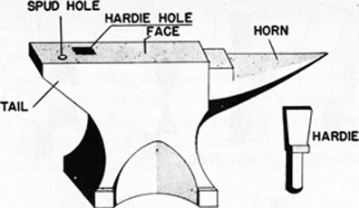
133. Forging Tools.-Some vises have a small anvil, as explained previously, but a larger anvil is also a very handy piece of equipment to have aboard ship. The face or main working surface of the typical anvil shown in Fig. 113 is made of tough steel. A square hole extends through the anvil top to hold the hardie, which is used for cutting metal bars and rods. The metal to be cut is placed
123
FIG. 113. ANVIL. AND HARDIE.
over the hardie and struck with a hammer or sledge. The end of the anvil opposite the hardie hole has a pointed or cone-shaped horn, over which curved portions of bars and rods may be formed.
The top surface of the anvil should be treated with care so as to avoid dents and scratches. Its primary purpose is to provide a working surface that will support the metal while it is being pounded into shape. This surface forms or shapes part of the object being forged, so the smoother it is, the better the job. It is therefore not advisable to use a chisel, for example, to cut metal on the anvil, unless the surface is protected against injury.
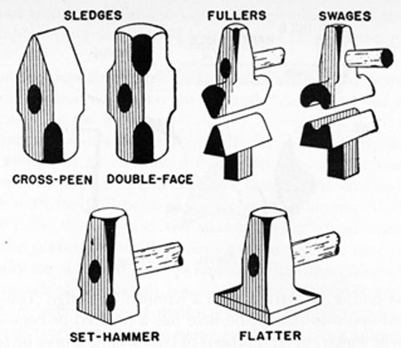
Sledges are used for heavy forging. Swages are used in matching pairs to shape round or oval objects. Fullers are used to shape round inside corners and inside angles. The set hammer and the flatter are used to smooth and finish flat surfaces. These tools are shown in Fig. 114.
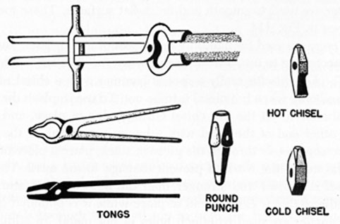
Tongs are used for handling hot pieces of metal. Their jaws differ according to use, otherwise the many varieties are much alike.
The hot chisel is really a special hammer with a chisel edge. It is used only when hot metal is to be cut. To use it, place the metal on the anvil, set the hot chisel cutting edge in place, and strike the other end of the head with a hammer or maul. If the cut is to be completely through the piece of stock, place a piece of scrap metal under the work to prevent damage to the anvil. The cold chisel is heavier and stronger than the hot chisel. It also has a handle so that it can be held in place while it is pounded on.
Punches are used to punch holes in hot metal. In addition to the round punch shown in Fig. 115, there are also square,
124
FIG. 114. FORGING HAMMERS.
rectangular, half-round and oval punches. They too are used only on hot metal.
134. Hoists.-Quite frequently it is necessary to lift various parts of an engine or other piece of equipment, and in some cases a complete unit must be lifted. There are many devices employed to do heavy lifting, but one of the most common is the hoist, generally known as a "chain falls." Of the several types of hoists, the
FIG. 115. FORGING TOOLS.
125
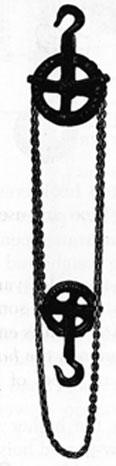
differential, the spur-geared, the screw-geared, and the ratchet lever types are found most frequently aboard ship.
135. Differential Chain Hoist.-The differential chain hoist, Fig. 116, is a simple chain hoist, designed for service where comparatively light loads are occasionally handled. It consists of a pair of pocketed chain wheels above and a single wheel below. The endless chain passes over one upper sheave, down around the bottom block, and then over the other upper sheave.
FIG. 116. DIFFERENTIAL CHAIN HOIST.
The differential hoist is light and easily handled and has few parts. Because of its reliability and simplicity it is especially valuable for ordinary hoisting purposes where more powerful hoists are not required. This type of hoist is made with capacities of 1/4 ton to 2 tons.
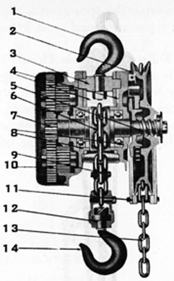
136. Spur-Geared Chain Hoist.-The hoist shown in Fig. 117 is of the spur-geared reduction type. This unit may be constructed with either single or double chain, and is a fast, powerful and durable mechanism. It can handle loads up to 40 tons, depending upon its construction.
Heavy suspension plates connect the top hook crosshead and the load sheave of the spur-geared hoist. These plates also directly support the saddle used in the double-chain arrangement, eliminating the need for a top yoke, and reducing weight and headroom.
The load sheave is mounted on ball bearings which are enclosed to protect them from grit and dust. The automatic load brake, which holds the load in any position, is also protected by a dust guard. A continuous pull on the hand chain is required to lower the load.
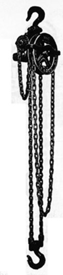
137. Screw-Geared Chain Hoist.-Where the higher speed of a spur-geared hoist is not required, the screw-geared hoist, Fig. 118, is recommended. It is well adapted for portable use, and though light, is powerful and durable. It holds the load securely, and will not lower except as the hand chain is pulled. This is an excellent hoist for temporary and occasional service, as it may be moved readily to meet an emergency. It is also adaptable for horizontal work. The worm gear makes this hoist compact for lifting loads in cramped places and close up to the overhead.
The screw-geared hoist is operated on the worm wheel and screw principle. The hand chain drives a sprocket wheel directly keyed to the worm shaft. The worm meshes in the worm wheel, which in turn drives the shaft holding the two load sheaves.
The hoist is operated by a comparatively light chain pull. With
127
FIG. 118. SCREW-GEARED CHAIN HOIST.
a 1-ton hoist, for example, one man with an approximate pull of 87 pounds can lift 2,000 pounds. However, the relatively large overhaul of hand chain required to lift the load makes it proportionately slow in operation. The capacity of this type of hoist ranges from 1/2 ton to 5 tons.
138. Ratchet Lever Hoist.-The ratchet lever hoist, Fig. 119, is designed to function as a general purpose tool for pulling and hoisting, having the characteristics of light weight and minimum distance between hooks. It also has self-actuated load brakes, a ratchet or universal action to permit use in congested quarters, and is compact and efficient.
The ratchet lever hoist operates by means of a ratchet, which actuates a lifting sprocket. The ratchet action permits short strokes on the handle with the load supported on the brake at any point of the lifting action. When lowering the load, the handle is operated in the same way as when lifting. The change from hoisting
128
FIG. 119. RATCHET LEVER HOISTS.
to lowering is easily accomplished and controlled by a small thumb turn on the handle.
The capacity of the ratchet lever hoist is from 3/4 ton to 6 tons, depending upon the number of chains. In Fig. 119, for example, the 1-chain hoist has a capacity of 3/4 ton to 1 1/2 tons; the 2-chain hoist, 3 tons; and the 4-chain hoist, 6 tons.
139. Whatever the type of hoisting device used, care must be taken to safeguard the operator and other personnel working on or near the hoisting operation, and for this reason the following precautions should be observed :
1. Be sure that the lifting gear is heavy enough to carry the load.
2. Be sure that none of the links in the chains are twisted.
3. Be sure that the hitch is made in the correct manner, so that nothing can slip when the load is picked up.
4. Do not start the lift until everything is clear.
5. Keep all personnel clear of the piece being lifted, so that if anything should slip or break no one will be injured.
129
6. Keep all personnel out from under the piece that is being lifted.
7. When the load might swing, as would occur at sea, be sure to have suitable stay lines to hold the piece in position.
8. After a lift has been made, it is not good practice to leave the load hanging on the hoist without some other support. Blocking should be used to assume most of the load, thus keeping only a moderate strain on the hoist.
9. When a piece of machinery has been lifted and moved to another position, always make sure to set it down on a secure foundation. It is often advisable to lash it down securely to prevent accidental movement.
140. Tube Expanders.-It is often necessary aboard ship to expand or "roll in" tubes in boilers, condensers, coolers, etc., a process that involves the use of a tube expander. A typical tube expander for use on the generating tubes of a boiler is shown disassembled in Fig. 120. An expander that would be used for rolling and belling
a. expander cage
b. straight and belling rolls
c. mandrels, various diameters
FIG. 120. EXPANDER FOR BOILER GENERATING TUBES.
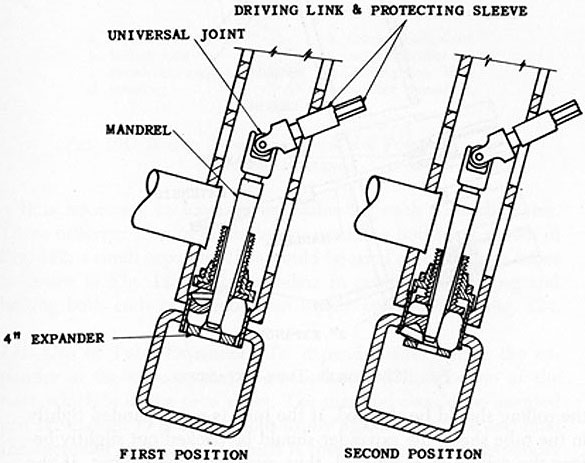
both ends of the short nipples that connect the headers to the drums in some boilers, is shown in Fig. 121.
As shown in the illustration, a tube expander consists of a cage containing the rolls, a slightly tapered mandrel which expands the rolls, and a wrench for turning the expander. Both straight and belling rolls are used in the expanders shown in Figs. 120 and 121, making it possible to expand and bell a tube in one operation.
130
a. expander cage
e. driving link, short
b. belling rolls
f. universal joint
c. mandrels, various diameters
g. driving link, long
d. coupling
h. ratchet wrench
i. straight rolls
FIG. 121. BOILER TUBE EXPANDER FOR FORWARD AND REVERSE ROLLING.
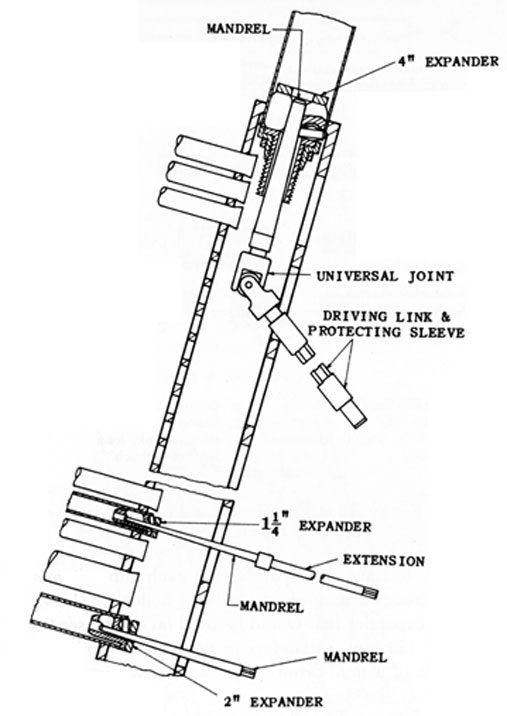
It is necessary to have an expander for each tube diameter. Three different sizes of expanders as used in a boiler are shown in Fig. 122; a small expander that would be used on condenser tubes is shown in Fig. 123; and expanders in position for rolling and belling both ends of a mud-drum nipple are shown in Fig. 124.
141. Use of Tube Expander.-To expand a tube, place the expander in the tube so that the rolls bear on the portion of the tube which is in the tube sheet. The mandrel should be inserted just far enough to press the rolls firmly against the tube and hold the expander in place. A wrench is then applied to the expander mandrel and the expander is turned clockwise. The progress of the rolling must be watched carefully, and rolling stopped when the tube is expanded enough to obtain a tight joint. Particular attention should be paid to the action of the belling rolls, when fitted, for if the expander is started too far in the tube it will make too large a bell before the tube is tightened. When belling rolls are being used and it is observed that the tube has sufficient bell,
131
FIG. 122. BOILER TUBE EXPANDERS.
the rolling should be stopped. If the tube is not expanded tightly in the tube sheet, the expander should be backed out slightly before the rolling is completed, thus avoiding over-belling. If the tube tightens in the seat first and does not have sufficient bell, move the mandrel outward slightly, set the expander farther into the tube, and continue the rolling as previously explained.
Tubes should be expanded just enough to obtain a tight joint that will not leak when a hydrostatic test is applied. Excessive rolling will cause a reduction of the tube wall thickness and
132
FIG. 123. CONDENSER TUBE EXPANDER.
produce weak joints. It also tends to enlarge the tube holes, making it difficult to maintain tight joints. If a tube hole should be excessively enlarged, a ferrule might have to be installed in the tube sheet to return the hole to normal size.
When using an expander, the rolls and mandrel should be well lubricated with fairly heavy lubricating oil. After each use, clean the expander and lubricate it again, if necessary, before rolling the next tube. Maintain the rolls in good condition and do not attempt to use chipped or cracked rolls. Always clean and oil the expander when storing it for future use.
FIG. 124. EXPANDING AND BELLING MUD-DRUM NIPPLES.
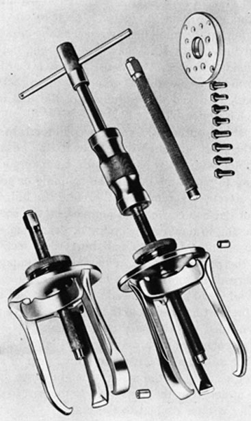
142. Coupling and Gear Puller.-A 3-jaw puller, suitable for removing couplings, gears, etc., from shafts, is shown in Fig. 125. This tool is designed to exert a strong, uniform pull, and is arranged for convenient use. Spring tension helps to hold the jaws
133
1. puller jaws
5. puller wrench
2. stud
6. special puller plate
3. yoke
7. cap screws
4. locking nut
8. screw-point protector
FIG. 125. COUPLING AND GEAR PULLER.
on the work, and when the locking nut is screwed down against the yoke the jaws are locked in position, causing the puller to maintain its grip until the locking nut is backed off. This arrangement permits both hands to be used for the actual pulling of the gear or coupling.
In order to use the puller, the jaws are hooked over the coupling or gear, and the centering tip of the stud is centered in the counter-
134
sink in the end of the shaft. For shafts without countersinks a special screw-point protector is used to prevent damage to the centering tip. By applying a wrench to the hexagon head of the stud and turning the stud clockwise, a strong pull is exerted on the part being removed. Always use a wrench that is a good fit on the hexagon end of the stud, as otherwise the corners of the hex may be rounded off and the usefulness of the tool impaired. A socket wrench is preferable.
When the stud is turned, the resulting pull tends to remove the work from the shaft, although sometimes it may be necessary to assist by tapping with a soft hammer or a hammer and a piece of wood. Be sure to tap at the hub of the coupling or gear, and not at the circumference. Tap evenly all around the hub, so that the work will not become cocked and jammed on the shaft.
Before starting to remove a coupling or gear from a shaft, it is advisable to examine for nicks and burrs that section of shaft over which the part must slide, removing such imperfections as may be observed. In some cases a film of oil or grease or a thin coating of white lead applied ahead of the work will facilitate its removal. If the part has rusted to the shaft, the use of penetrating oil may be needed to break up the corrosion.
A special circular plate is provided with the tool shown in Fig. 125 so that the puller may be used on a fiber gear or similar part, where pulling directly on the material might cause damage. The plate can be attached by the cap screws to the part to be removed, and the puller is then applied to the plate.
It should be noted that the jaws of the puller are reversible, permitting their use through an opening for inside pulls on bushings, sleeves, etc. When used in this way, a piece of stock of sufficient length for the stud to bear against would have to be placed in the opening. The yoke of the puller is also made with 2 sets of jaw slots, allowing the jaws to be moved closer to the center for better gripping power on small jobs.
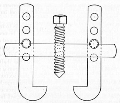
If a suitable puller is not available, it is possible to make a satisfactory tool from material available aboard ship, the material to be used depending in part on the job to be done. For extra heavy work the puller would have to be made from heavier and stronger stock.
A puller such as shown in Fig. 126 can be made from scrap metal and will accomplish the work adequately. Remember that the center piece must be wide and heavy enough to allow a hole to be
135
drilled and threaded. To make the stud, a piece of stock of suitable length is threaded, and then one end squared so that a wrench will fit on it. The two jaws should be cut from heavy enough material so that they will not bend when the force is applied. The adjusting holes may be cut as desired.
FIG. 126. HEAVY-DUTY PULLER.
143. Portable Lamps.-Portable electric lamps, also called "extensions," are often used when work is being done aboard ship. Before plugging in an extension, the plug and cable should he inspected carefully, especially that portion of the cable which enters the handle of the lamp. If frayed insulation is noted, it should be reinforced with friction tape. If broken insulation is observed, the cable should be repaired or discarded. The lamp should always be protected by an efficient guard.
When using an extension, make sure that the cable does not drop or lie in water. When working in confined spaces, do not lie on the cable or let it become wound around the body. Be especially careful when working in damp areas or when perspiring heavily. It is always a reasonable precaution to wear leather gloves and to keep the footgear dry.
144. Fuse Pullers.-The fuse puller shown in Fig. 127 is designed for easy and safe removal of electric fuses. It is made of laminated fiber or laminated plastic, as either material eliminates danger of shock and injury to the workman.
136
FIG. 127. FUSE PULLER.
A fuse puller should always be used when pulling or replacing cartridge fuses, as removal by hand is dangerous, and improper removal also may bend and damage the fuse clips. Fuse pullers are available in various sizes, and will handle fuses from 1/4 inch to 3 inches in diameter.
145. Hand Fire Extinguishers.-It is logical to include hand fire extinguishers in a lesson that deals with engine-room tools, because they actually are the tools that are immediately at hand to combat fire aboard ship. When the existence of a fire in its early stages is noted, the prompt use of some kind of hand fire extinguisher is of the utmost importance. This is especially true aboard ship where fire is always a grave danger. Inflammable cargo and fuel are likely to be present in large quantities; narrow alleyways tend to create drafts that help to spread a blaze more rapidly; and outside help may be far away. To extinguish a small fire before it can develop into a major disaster, someone must act promptly and efficiently with the right kind of equipment.
Hand fire extinguishers are necessary even though other types of fire fighting equipment are provided, and it is essential that they be intelligently handled during the excitement of a fire, so that the maximum of fire extinguishment can be accomplished in the minimum of time. While the contents and methods of operation of the various types of appliances are generally apparent from their nature and are indicated prominently on each extinguisher, it is important that all hands learn about them in advance. It is too late to begin to study fire extinguishers after the fire has started.
146. Classification of Fires.-For all practical purposes there are 3 general classes of fires:
Class A fires are fires in ordinary combustible materials, such as wood, paper, rubbish, etc., where the quenching and cooling effects of quantities of water, or solutions containing large percentages of water, are of primary importance.
137
Class B fires are fires in flammable liquids, greases, etc., where a blanketing effect is essential.
Class C fires are fires in electrical equipment, where the use of a non-conducting extinguishing agent is required.
Several types of hand fire extinguishers, the class of fire that each is designed to extinguish, and the method of extinguishment, are listed in the following tabulation:
Type of Extinguisher
Class of Fire
Method of Extinguishment
Soda-Acid
A
Cooling
Anti-freeze
A
Cooling
Foam
A,B
Smothering
Carbon Tetrachloride
A,B,C
Smothering
Carbon Dioxide
A,B,C
Smothering and cooling
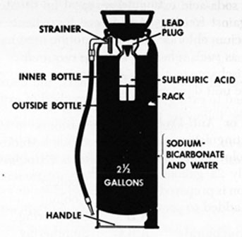
147. Soda-Acid Extinguisher.-Soda-acid extinguishers, one of which is shown in Fig. 128, are made in two principal sizes, the smaller one having a liquid capacity of 1 3/4 to 1 1/2 gallons, and the other containing 2 1/2 gallons. The chemicals used in this extinguisher are (1) a powdered chemical (bicarbonate of soda) designed to be dissolved in water contained in the extinguisher shell, and (2) a liquid chemical (sulphuric acid) contained in a loosely stoppered bottle that is held in a vertical position in the apparatus. The extinguisher is kept and carried vertically until it is to be used to extinguish a fire. It is then inverted, which causes the contents of the bottle to mix with the soda solution. Pressure is created by the chemical reaction and a stream of chemical is expelled through the hose. The extinguisher is usually most effective when used close to the fire, but the stream can be directed, if necessary, from a distance of 30 to 40 feet horizontally.
Soda-acid extinguishers are effective on incipient fires in ordinary combustible materials. They are not effective on fires in flammable liquids and greases. Their use on fires in electrical equipment such as switchboards, panels, motors, etc., is not recommended.
Soda-acid extinguishers should be kept full (to filling mark) at all times, and should be recharged with fresh solution annually as well as immediately after any use. All parts should be washed thoroughly with water and the water drained through the hose
138
FIG. 128. SODA-ACID EXTINGUISHER.
before recharging. The extinguishers should be examined at regular intervals to make sure that they have not been tampered with or removed from their designated places. They should also be inspected to see that they are properly filled and that the orifice of the hose is not clogged. In addition, at least once yearly when emptying and recharging, all parts of the extinguishers, including the gasket and hose, should be examined carefully for deterioration or injury. Extinguishers or parts which are not in good condition should be replaced.
Recharging of extinguishers should always be done under capable supervision, and the date of recharging and signature of the person who performed it should be entered on the tag attached to the extinguisher. It is also important that acid bottles and their corresponding stoppers, when replaced, should be exact duplicates of those originally provided, as otherwise the discharge may be impaired or the extinguisher rendered inoperative.
When preparing the soda solution, the powdered chemical should be thoroughly dissolved in water outside the extinguisher in accordance with instructions on the extinguisher or as provided by the manufacturer of the chemical. The water should be lukewarm but never hot. A quantity of chemical charges supplied for use in the extinguishers must be kept on hand so that each unit may be recharged promptly after each use.
In localities where continued temperatures lower than 40°F
139
may prevail, soda-acid extinguishers must be situated so as to be protected against freezing. Anti-freeze ingredients such as common salt, calcium chloride, etc., must not be used in extinguishers of this type, as such substances may either reduce the effectiveness of the discharge or change its nature, or may cause corrosion and make the unit dangerous for use.
148. Water or Anti-Freeze Solution Extinguishers.-Approved hand fire extinguishers designed to contain either water or an anti-freeze solution are made in two sizes, with liquid capacity of approximately a gallons and 5 gallons, respectively. The antifreeze solution is prepared from a calcium chloride base with other components added to prevent corrosion and deposits on the
FIG. 129. WATER OR ANTI-FREEZE SOLUTION EXTINGUISHER (PUMP-TYPE).
140
operating parts of the extinguishers. This type of apparatus is effective in the same cases as the soda-acid extinguisher, that is, Class A fires where water can be used effectively.
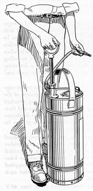
These extinguishers are often pump-operated, as shown in Fig. 129, and can be discharged intermittently, with the force, length and duration of the stream being dependent on the operator. It is not feasible, however, to operate this particular type of extinguisher while carrying it about.
The same general precautions concerning inspection and recharging that are recommended for soda-acid extinguishers must be enforced, and when located where low temperatures may be encountered, water-type extinguishers must be protected from freezing unless charged with the anti-freeze solution. The operation of the pumps should also be tested by operating them several strokes, discharging the solution back into the extinguisher. A few drops of light lubricating oil should be placed on the pump rod packing.
Some water-type extinguishers contain a carbon-dioxide cartridge instead of a pump. When this extinguisher is inverted, the cartridge is perforated, releasing gas which builds up a pressure in the extinguisher and causes it to discharge. All cartridges should be removed and examined when cartridge-operated extinguishers are inspected, and should be weighed on an accurate scale to detect loss of pressure by leakage. It is recommended that a new cartridge be used to replace any which shows a loss of 1/2 ounce or more from the original weight stamped on it.
When recharging extinguishers with anti-freeze solution, the chemical should be thoroughly dissolved in water outside the extinguisher, in strict accordance with instructions provided by the manufacturer of the extinguisher or chemical. The water should be warm and the solution should be poured through a fine strainer when placing it in the extinguisher.
Common salt or other unspecified chemicals should not be used in anti-freeze solution extinguishers, as they may corrode or otherwise be made dangerous for use. Cartridges other than those furnished by the manufacturer should not be used in cartridge-operated extinguishers.
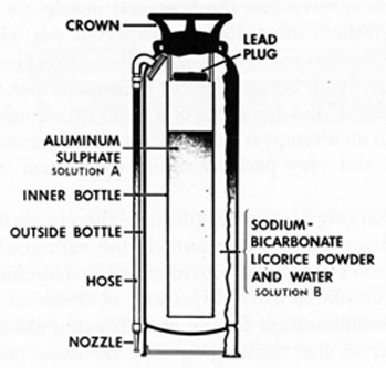
149. Foam Extinguishers.-Foam extinguishers are made in sizes up to 5 gallons. The chemicals used are bicarbonate of soda and a foam stabilizing agent dissolved in water, for the outer compartment,
141
and aluminum sulphate dissolved in water for the inner cylinder. The extinguishing agent is a foam which results from the reaction of the two chemical solutions. A typical foam extinguisher is shown in Fig. 130.
FIG. 130. FOAM EXTINGUISHER.
Foam extinguishers are designed to be carried to the fire by means of the top handle and must be inverted for use. When the chemicals mix as a result of the extinguisher being inverted, foam is produced and a pressure created within the container, causing a stream of foam to be expelled through the hose. This stream can be directed effectively from a distance as great as 30 to 40 feet horizontally.
On flammable liquid fires, the best results are obtained when the discharge from a foam-type extinguisher is played against the wall of the enclosure containing the liquid, just above the burning surface, so as to permit the natural spread of the foam over the burning liquid. If this cannot be done, the operator should stand far enough away from the fire to allow the foam to fall lightly upon the burning surface. The stream should never be directed into the burning liquid. Where possible, the operator should walk around the fire while directing the stream, so as to obtain maximum coverage during the discharge period.
For fires in ordinary combustible materials the force of the stream may be used, or the foam may be used to coat the burning
142
surface, according to the conditions. The use of these extinguishers on fires in electrical equipment is not recommended.
Foam extinguishers should be recharged annually as well as immediately after use. When recharging them, all parts should be washed thoroughly with water and the water drained through the hose. This ensures that the hose and nozzle are not clogged. Foam extinguishers must also be inspected periodically as explained previously in connection with other kinds of extinguishers, particular care again being taken to make sure that the hose and nozzle are clear. If the discharge of a foam extinguisher should be clogged when an attempt is made to use it, the pressure can cause an explosion and very possibly injure the person using the extinguisher.
When recharging foam extinguishers, the chemicals should be thoroughly dissolved in water outside the extinguisher, in exact accordance with instructions provided by the manufacturer. Lukewarm water should be used. A quantity of chemical charges supplied by the manufacturer for use in such extinguishers should be kept on hand so that recharging may be done promptly after each use.
Where low temperatures may be expected, foam extinguishers must be located so as to be protected against freezing. Anti-freeze ingredients such as common salt, calcium chloride, etc., must not be used.
150. Vaporizing Liquid (Carbon Tetrachloride) Extinguishers.-Carbon tetrachloride extinguishers are made in several sizes up to a liquid capacity of 3 1/2 gallons. The extinguishing agent used is a non-conducting liquid having a carbon-tetrachloride base combined with other chemicals which depress the freezing point to 50° below zero and help to avoid corrosion, etc. An extinguisher of this type is shown in Fig. 131.
When the self-contained pump of this extinguisher is operated, the pumping action expels a stream of liquid which is vaporized into a gas by the heat of the fire. In case of a fire in ordinary combustible materials, the stream should be directed at the base of the flames. On flammable liquid fires, best results are obtained when the discharge from the extinguisher is played against the inside of the enclosure containing the liquid, just above the burning surface, the same general procedure being followed as in the use of a foam extinguisher.
143
FIG. 131. CARBON TETRACHLORIDE EXTINGUISHER.
Carbon tetrachloride extinguishers are effective on incipient fires in electrical equipment, where the use of a non-conducting extinguishing agent is essential. When using these extinguishers, however, especially in confined and poorly ventilated spaces, precautions should be taken to avoid breathing for extended periods the vapors or gases liberated, as toxic effects may be experienced.
The extinguishers should be kept filled at all times and should be refilled immediately after use. They do not need to be protected against freezing, when charged with the specified liquid. Caution: Do not use water for any purpose in extinguishers of this type.
At least once yearly, carbon tetrachloride extinguishers must be examined as to condition of the pump and for deterioration or injury due to misuse. At these inspections all pumps should be tested by discharging a portion of the liquid with the stream directed alternately upward and downward. Extinguishers which are not in good condition should be replaced; others should be refilled by pouring in enough liquid to replace that which was discharged. The date of recharging and the signature of the person who performed it should be placed on the tag attached to each extinguisher.
A quantity of the special fire extinguishing liquid supplied for use in the extinguishers should always be kept on hand. No liquid other than that furnished by the extinguisher manufacturers should be used in the extinguishers, as it might make the extinguisher inoperative or dangerous for use.
144
151. Carbon Dioxide (CO2) Extinguishers.-Carbon dioxide extinguishers, Fig. 132, are made in several principal sizes, ranging from 2 1/2 to 25 pounds of carbon dioxide. To use this type of extinguisher the valve is opened and the gas discharged upon the fire through the hose and cone. The discharge has a range of approximately 8 feet.
FIG. 132. CARBON DIOXIDE EXTINGUISHER.
The discharge of a carbon dioxide extinguisher should be directed at the base of the flames in all types of fires, and should be applied to the burned surface even after the flames are extinguished. This tends to deposit carbon dioxide snow as a coating on the hot surfaces and any glowing material, thus reducing the chances of a reflash.
On flammable liquid fires, best results are obtained when the discharge from the extinguisher is employed to sweep the flame off the burning surface, applying the discharge first at the near edge of the fire and gradually progressing forward, moving the discharge cone very slowly from side to side.
Carbon dioxide extinguishers are effective on fires in electrical
145
equipment, but are not suitable for use on deep-seated fires of wood, paper and rubbish, as such fires require the quenching effect of water for complete extinguishment.
When using these extinguishers, the same precautions should be taken to avoid breathing the liberated gases as are recommended in the case of carbon tetrachloride.
At least once yearly the extinguishers should be examined as to weight and for deterioration, as reweighing is the only method of determining whether or not a carbon dioxide extinguisher is fully charged. They should be weighed on an accurate scale, and any unit that shows a loss of 10% or more of the rated capacity stamped on it should be recharged. Unless recharging facilities are maintained on board ship, it will be necessary to send depleted extinguishers ashore for recharging. All extinguishers should be refilled as soon as possible after use, even though only partly discharged.
Carbon dioxide extinguishers do not need to be protected against freezing.
146
This page blank.
147
ENGINE-ROOM TOOLS, PART 2
EXAMINATION QUESTIONS
Instructions:-Study the lesson very carefully before considering the examination questions. Then read each question slowly and be sure that you understand it. When answering the questions, always take sufficient time, prepare the answers in your own words, and do your best work. In arranging your answers, please leave space between them so that the instructor will be able to write in helpful explanation, should you make an error or overlook an important point. After the answers are completed, check them again very carefully; make sure that all questions are taken care of; correct each error that you find; and mail your work to us.
1. What is the advantage of fillister heads on cap screws?
2. (a) What is the purpose of "safety wire"?
(b) How it is used?
3. Explain how to use a stud driver.
4. Explain how to remove a small stud that is broken off in the hole.
5. Explain how to use "shakeproof washers."
6. If the note (5/16-24 N.F.-4) were observed on a blueprint, what would it mean?
7. What size tap drill should be used when drilling a hole which is to be tapped:
(a) For a 7/8-inch stud (N.C. thread)?
(b) For 1-inch pipe?
8. Briefly describe the procedure followed when tapping a threaded hole in steel.
9. Explain how to prepare a piece of steel rod for cutting a thread with a stock and die.
148
10. The distance between the faces of two 1-inch pipe fittings is 3 ft. 1 1/2 in. What length of pipe should be cut and threaded so as to connect the two fittings?
11. What should always be done after cutting a piece of pipe?
12. Give 4 precautions that should be taken when using a reamer.
13. It is necessary to install a standard taper pin, the large diameter of which is approximately 23/32 in.
(a) What size drill should be used?
(b) What size taper reamer should be used?
14. (a) Explain how to test the extent and distribution of bearing area of a bearing.
(b) If the bearing area is not uniformly distributed to the proper extent, what should be done? Explain in detail.
15. Explain how to make a full gasket for a joint on the water end of a pump, using sheet gasket material. (A full gasket is one that covers all of the joint surface.)
16. Explain the general precautions that should be taken when using a hoist.
17. Explain how to pull a small gear from a shaft.
18. What precautions should be taken when using a portable electric lamp?
19. If a fire is discovered in a motor in operation, the motor should be shut down immediately, if possible.
(a) What kinds of fire extinguishers are recommended for use on this type of fire?
(b) What precautions should be taken when using either of these extinguishers?
20. A ship is expected to pass through a region where low temperatures may be encountered.
(a) What types of fire extinguishers must be protected against freezing?