In order to understand the theory of operation
of a stabilized sonar system, it is necessary first
to comprehend the general nature of the stabilization problem. A brief explanation of the stabilization problem is provided in the first part of this
chapter. Following this explanation, the
stabilization problem as it affects the two basic types of
stabilized sonar systems is described. Readers not
familiar with fire control symbols should refer to
the Appendix before studying this chapter. A brief
summary of the stabilizing system is given at the
end of this chapter.
The Stabilization Problem
The position or direction of a line in space-whether it is a line of sight, a line of sound, or any
other line-is specified by angles measured about
certain reference axes the positions of which are
known. In many fire control systems, the position
of the line of sound is established by angles measured about axes which are horizontal and vertical
in space. These horizontal, true-zenith axes are
used to measure such angles as relative bearing
Brq and depression Eq for the dual single-axis and
three-axis systems. These systems are used in the
two types of stabilized sonar equipment.
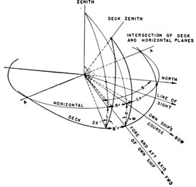
Equipment mounted on the plane of the deck,
or on a plane parallel to the deck, however, positions a line in space in response to information
which is ultimately referred to one of the deck
systems of coordinates in which the reference axes
are perpendicular and parallel to the deck. This
information is called a deck, deck-zenith system of
coordinates. These coordinates apply to such
angles as sonar train B'r'q and depression E'q's for
the dual single-axis system. (See figure 9-7.)
Ordinarily, the horizontal, true-zenith axes and
the deck, deck-zenith axes are in alignment only
at the infrequent intervals when the deck plane is
horizontal. Most of the time the two sets of axes
are being continuously displaced with respect to
each other by the tilting movement of the deck.
In order to measure the degree of displacement
of these axes from each other, a stable element is
used. The stable element is normally trained to
B'r, the bearing of the main battery director.
Thus the stable element measures these angles
using B'r as a reference. In order to stabilize the
sonar equipment the reference line about which the
angles are measured must be changed from B'r to
the bearing of the sonar target. This conversion
is the function of the stabilization computer.
The method by which a stabilization computer,
in conjunction with a stable element, is used to
relate information measured with respect to two
different systems of coordinates for the purpose of
stabilizing a sonar system is illustrated by the
following problem. Suppose a ship is riding at
anchor with the sonar equipment trained on a
stationary target. As determined by the sonar
operator, the line of sound is fixed in space and the
angles of relative sonar bearing Brq and depression
Eq, which establish the position of the line, have
fixed values because they are measured with
respect to a system of horizontal, true-zenith
coordinates. But the position of the line of sound
in the dual-single axis system is established by the
sonar train B'rq and the depression E'q', which
are measured with respect to a deck, deck-zenith
system of coordinates. Because the deck,
185
deck-zenith axes are continually moving in space as the
ship rolls and pitches, these angles are continually
changing in value. If the target moves, the
changes in the values of these angles also become
a function of the movement of the target.
To determine the varying values of B'rq and
E'q' in this problem it is necessary to relate mathematically the fixed values of Brq and Eq with
the continually varying angles that measure the
roll and pitch of the ship. The fixed values of
Brq and Eq are supplied to the stabilization computer from the sonar equipment, and the continually varying values of the angles measuring the
roll and pitch of the ship are supplied to the
stabilization computer from a stable element.
The stabilization computer combines the trigonometric functions of these angles into the proper
mathematical equations from which the
continuously varying values of B'rq and E'q' can be
computed. The computed values of these angles
are then applied to the drive mechanisms of the
system to keep it continuously positioned on the
desired line of sound.
Thus the function of the computer is to receive
angles measured with respect to one set of coordinate axes and the angles of roll and pitch (or angles
convertible to roll and pitch) and to compute from
this data angles measured with respect to another
set of coordinate axes.
The stable element is the piece of equipment
which provides a fixed system of axes (to which
the variable angles caused by roll and pitch may
be compared)-and the gyroscope is the heart of
the stable element. It is important therefore to
understand the characteristics of a gyroscope.
Fundamentals of the Stable Element
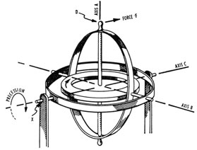
PROPERTIES OF A FREE GYRO
If a heavy wheel is mounted so that its shaft is
free to turn in any direction, it is known as a free
gyroscope or free gyro. Usually the mount is constructed with three mutually perpendicular axes
about which the wheel may turn. Thus in
figure 9-1 the wheel is free to spin about axis A,
Figure 9-1 -Properties of a free gyro.
to turn about B, and to turn about C. The gyro
wheel is located so that its center of mass coincides
with the intersection of these three axes.
For purposes of illustration, all bearings are
considered to be without friction. It is evident
that the gyro wheel, when not rotating, is in a
state of indifferent or neutral equilibrium; that is,
it remains in any position in which it is placed.
In addition, it yields in the direction of any force
which tends to rotate it about one of its axes, just
as any free mass moves in the direction of an
applied force.
If the wheel is set spinning rapidly, it exhibits
entirely new phenomena. It resists rather than
yields to an applied force. A force, F, applied at
point D of figure 9-1, produces a torque about the
axis B. This torque, instead of rotating the frame
in the direction of the applied force as it would do
if the wheel were not spinning, is opposed by the
frame.
Additionally, the wheel starts to rotate slowly
(precess) about axis C in the direction indicated.
If the mount is without friction, as was assumed,
this action continues as long as the force is applied
at D.
Similarly, a force applied at D in a plane through
axis B tends to rotate the wheel about the C axis
but the gyro resists this motion and turns instead
about the axis B.
A pressure applied to the gyro wheel frame
always results in reaction forces at the bearings.
If, as in the cases illustrated by this figure, the
186
applied force and bearing reaction are not in the
same straight line, these forces form a couple
which tends to rotate the gyro wheel axis. The
free gyro does not, however, turn about the couple
axis but rotates about another axis perpendicular
to the couple axis. Thus, in figure 9-1, a couple
about axis B results in a rotation or precession of
the wheel and frame about C.
Experiments show that, neglecting inertia, the
gyro does not resist translation, that is, motion
which keeps the spin axis A parallel to its original
position.
RIGIDITY OF PLANE
Rigidity of plane is that property of a gyro by
which the gyro tends to maintain the plane of its
wheel parallel to its original position in space.
This property results from the fact that a mass in
motion can have its direction of movement
changed only by applying a force to the mass.
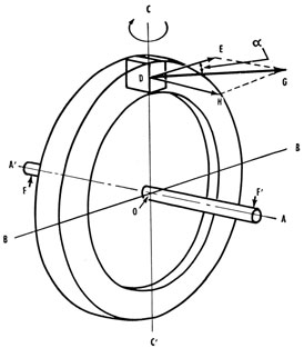
PRECESSION
Precession is the name given to the slow movement of a gyro wheel resulting from the application
of an external force or couple which tends to rotate
the spin axis of the gyro.
Figure 9-2 shows a rapidly spinning gyro in
which the axis of spin is A. A couple represented
by forces F-F' tends to twist the gyro wheel about
the couple axis B perpendicular to, and in the same
horizontal plane as, A. Consider a small section
of the wheel rim at D. Due to the rotation of the
wheel, section D has a high linear velocity in the
direction DE.
The couple F-F' exerts a force upon this small
mass along DH and so accelerates it in this direction. During a short interval of time this acceleration gives the particle a component of velocity
DH. The result of combining velocities DE and
DH is a new velocity DG, equivalent to a rotation
through an angle about axis C. Therefore the
effect of a couple F-F' acting about the B axis is to
cause a slow rotation of the gyro wheel about the
C axis. This rotation is known as precession.
In order to obtain a high rigidity of plane and
slow precession, gyro wheels are made heavy in
weight and are operated at a high rate.
It has been shown that if the gyro wheel is
freely supported as in figure 9-1 and a force or
couple is applied about the axis B, the wheel does
Figure 9-2 -Precession.
not turn about an axis C at right angles to the
axis of the applied couple.
To determine the direction of precession apply
the following rule: The axis of a freely mounted
gyro tends to turn or precess in such a direction
that it becomes parallel to the axis of the applied
torque, by the shortest path, and with the rotation
of the wheel in the same direction as the applied
torque.
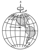
APPARENT ROTATION
Assume now that the gyro wheel supported by
its universal mounting as before is placed at the
equator of the earth with its A axis vertical, as
shown in position 1 of figure 9-3. To an observer
standing on the earth the wheel appears to rotate
at the rate of one complete turn in 24 hours. This
rotation might seem puzzling were it not remembered that it is the earth that is turning-not the
gyro.
EFFECT OF FRICTION
In the practical construction of the mounting
described, some friction is inevitably present at
the trunnion bearings. Assuming for the moment
that the bearings of the horizontal axis B (figure
9-1) have slight friction, it is apparent that the
187
Figure 9-3 -Apparent rotation.
earth's rotation applies a slight turning moment or
couple to the gyro wheel. A free gyro, however,
does not turn in the direction of an applied couple
but precesses around an axis 90° from the couple.
Consequently the slight friction in bearings of axis
B causes the gyro wheel to precess about the axis
C. With proper construction of bearings B this
precession may be made very slow.
In the case just described it was assumed that
the bearings determine the ability of a gyro wheel
to maintain its plane or rotation fixed in space
against the friction of bearings B. If, to take an
extreme case, the supporting frame were locked
Figure 9-4. -Effect of latitude.
about axis C (X, figure 9-1), the gyro wheel would
immediately lose its resistance to the friction of
bearings B and so would partake of the earth's
rotation just as if the wheel were not spinning.
The importance of extreme freedom about axis C
is therefore apparent.
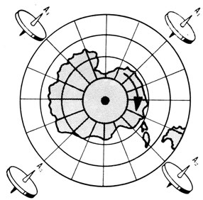
EFFECT OF LATITUDE
It has been noted that the earth's rotation
causes an apparent rotation of a gyro which is
set spinning with its A axis perpendicular to the
earth's surface. At the equator this apparent
rotation appears to be a straight backward
gyration (with respect to the earth's rotation) at
the rate of one revolution every 24 hours about a
north-south axis. At either pole this phenomenon
does not occur (again assuming frictionless bearings), because the gyro axis A is already parallel
to (or an extension of) the earth's axis, as in
figure 9-4. At any point or latitude between the
pole and the equator, however, the wheel appears
to gyrate once every 24 hours about an axis
parallel to the axis of the earth's rotation, and in a
direction opposite to that of the earth's rotation,
as in figure 9-5.
Figure 9-5 -Gyration between equator and pole.
COMPENSATION
In any application of the gyro to precision
instruments, corrections for the earth's rotation,
friction, acceleration, turning, and other factors
must be applied if the gyro is always to spin in a
fixed plane with respect to the earth's surface at
any latitude.
Compensations for these errors are not dealt
with here, as their operation is not essential in
understanding the principles of the stable element.
188
Stable-Element Construction
The stable element is used (1) to measure movement of the deck in level and crosslevel angles or
in roll and pitch angles, depending on the connections of the stable element, and (2) to transmit
these angles as synchro signals. The principal
part of the stable element is an electrically driven
gyroscope that establishes a horizontal-reference
plane from which the level and crosslevel angles
are measured.
There are three follow-up systems in stable-element equipments-the train, the crosslevel, and
the level follow-up systems. In some equipments
the train is locked on zero, and the outputs are in
terms of roll and pitch instead of level and cross-level. The follow-up system for train determines
the error between the bearing of the equipment
that is being stabilized and the bearing of the
training frame in the stable element. When the
stable element supplies roll and pitch, however,
the train follow-up system is not used and the
B'r input to the stable element is locked in the
zero position. In stable elements having outputs
of level and crosslevel, the train follow-up is
used to rotate the stable element to the bearing
of the equipment that is being stabilized.
The follow-up systems for level and crosslevel
are identical and are actuated by electric error
signals, which originate in the gyro unit. These
signals are amplified and are used for actuating
the level and crosslevel motors, which drive not
only the synchros transmitting the level and
crosslevel angles to the equipment to be stabilized
but also the level and crosslevel follow-up circuits.
If the stable element is modified and the train
input locked, the output is then roll and pitch
instead of level and crosslevel.
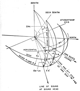
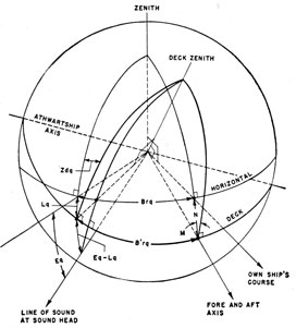
Level and Cross-Level Receiver System
A spherical diagram illustrating the relationship between the angles of level L, crosslevel Zd,
director train B'r roll M, and pitch N is shown in
figure 9-6.
Angular inputs which indicate the attitude of the
deck with respect to the horizontal are supplied to
the computer by a stable element. The space reference of the stable element is a gyroscope which
rotates about a vertical axis to maintain continuously an a-c electromagnet in a fixed position.
Above the electromagnet are two sets of follow-up
coils, the fields of which are at right angles to each
other, one for level L and the other for crosslevel
Zd control. Both sets of coils are supported on the
inner gimbal of two mutually perpendicular gimbals. When the motion of the ship displaces the
coils with relation to the electromagnet, follow-up
systems are actuated by the coils to move the gimbals in such a direction as to restore the original
position of the coils with respect to the electromagnet. The angular movement of the level and
crosslevel follow-up controls causes the signals
across the level L and crosslevel Zd transmitters to
change in correspondence with the attitude of the
gimbals and thus measure the attitude of the deck
with respect to the horizontal.
239276°-53-13
One of the stable elements from which the computer may receive tilt angle inputs is the Stable
Element Mk 6. This instrument is trainable and is
used usually in conjunction with the Gun Director
Mk 37. As the director trains to position a line of
sight, it generates a signal corresponding to the
angle of director train, B'r, which is transmitted by
synchro to the stable element in order to drive the
stable element through the same angle. Because
the stable element normally is trainable, its cross-level and level axes are rotated about an axis perpendicular to the deck and in a plane parallel to the
deck. Pitching and rolling which may occur at
the angle of director train are measured about the
level and crosslevel axes, respectively. Thus as
the stable element trains through B'r, continuously
changing values of L and Zd are generated for continuously varying values of B'r and are transmitted to the various stabilized equipments on the vessel. When the necessary electrical connections are
made the same angular values are received by the
computer.
If the tilt angles transmitted from a stable element, not locked on zero, were used directly in
making the stabilization computations for the various fire control systems serviced by the computer,
189
the train angle at which these tilt angles were
measured would also be required in the computations, thus needlessly complicating the computer
circuits. If tilt angles measured at the fore and
aft axis of the ship were used, where the angle of
train is zero, only the tilt angles would be required
for the stabilization computations and the computer circuits would become less complicated.
For this reason the functions of L, Zd, and B'r are
converted by the required trigonometric equations
Figure 9-6. -Spherical diagram illustrating various angles in sonar problems.
into the functions of N and M, which are the tilt
angles at the fore-and-aft axis.
The level and crosslevel receiver system performs this conversion. This system consists of
three input servos which are positioned through the
angles of level L, crosslevel Zd, and director train
B'r. The resolvers in these servos are connected
in such a manner that the components of these angular functions are related according to the equations in the functional diagrams shown in figure
9-11. The rotation of the servomechanisms accomplishes a continuous simultaneous solution of
these equations. The solution is in terms of the
angles of roll M and pitch N. If a gyro which has
been locked on zero is used, the angles supplied to
the computer are measured directly in roll and
pitch, eliminating the need for the level and cross-level receiver.
ROLL AND PITCH COMPUTER SYSTEM
The computer circuit, described in the section
on the level and crosslevel receiver, is located
partly in the level and crosslevel receiver and
partly in the roll and pitch computer. The two
resolvers in that part of the computer circuit
which is located in the roll and pitch computer
rack control two output servos, which, in turn,
position various resolvers through the angles of
roll M and pitch N.
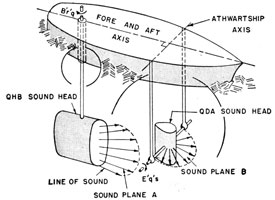
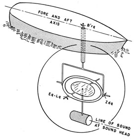
Dual Single-Axis Stabilization System
In the problem of determining a line of sound
to an underwater target with a dual single-axis
below-decks system like that of the QHB and
QDA, two sound heads rotatable about axes in
the deck must be positioned properly as shown in
figures 9-7 and 9-8.
Each sound head generates along a plane of
sound. The sound heads are rotated so as to
make their planes of sound intersect on the line
of sound to the target. Sound plane A is rotated
about an axis perpendicular to the deck through
the train angle B'r'q and sound plane B is rotated
about an athwartship axis parallel to the deck
through the tilt angle E'q's. Both of these angles
are measured with respect to deck, deck-zenith
coordinate axes, but the required fire control information is computed as relative bearing Brq and
the depression angle Eq, both measured with respect to horizontal true-zenith coordinate axes.
In order to position these sound heads properly,
the computed data Brq and Eq must be converted
through the use of M and N into B'r'q and E'q's
in the dual single-axis stabilization system and
transmitted in that form to the drive mechanisms
of the two sound heads.
Note that the spherical diagram indicates the
depression angle at the line of sound as E'q'. If
this were a two-axis system, E'q' would be the
proper depression order, but because of the QDA
sound head is not trainable, in the QHB-QDA
dual single-axis system, E'q's must be used instead.
The dual single-axis stabilization unit in the
computer consists of (1) two input servos which
are used to position mechanically two resolvers
through the angles Eq and Brq, (2) two resolvers
which are mechanically positioned through the
angles M and N by the servos in the roll and pitch
computer or the roll and pitch receiver, and (3)
two servos which are positioned by their resolvers
through the angles B'r'q and E'q's. The resolvers
are connected in such a manner that they relate
the functions of the four input angles in trigonometric equations which produce in simultaneous
solution the functions of B'r'q and E'q's for synchro
transmission to the drive mechanisms of the sound
gear.
Figure 9-8 -Dual single-axis system.
Three-Axis Stabilization System
In a three-axis below-decks system a line of
sound is positioned about three axes of rotation
relative to the deck, as shown in figures 9-9 and
9-10.
Although movement about the three axes of
rotation occurs simultaneously, for the sake of
explanation, the operation of the system may be
treated as though it occurred in sequence as follows.
The system must train in the plane of the deck to
position its crosslevel axis in a vertical plane
through the line of sound, but the train angle
input is computed in the horizontal-true zenith
angle of relative bearing, Brq. Therefore, this
angle must be converted by parts of the computer
circuit in the three-axis stabilization system
through the angles of roll M and pitch N into the
deck, deck-zenith angle of B'rq. Once it has been
positioned in the vertical plane through the line
of sound, the crosslevel axis is rotated through
the crosslevel angle Zdq until the level axis is
horizontal. Then the level gimbal is rotated
about the level axis through the level angle Lq to
bring the sound head into the horizontal plane.
From this point the level gimbal is tilted through
the depression angle Eq to bring the sound head
onto the desired line of sound. In actual practice,
the latter two steps are accomplished by continuously subtracting Lq from Eq. The angles Zdq
and Lq are derived by the simultaneous solution
of trigonometric equations relating M, and N,
and Brq.
The three-axis stabilization system utilizes two
sections in the Mk 59 computer. In one section,
resolvers are mechanically positioned by input
servos through the angles M, N, and Brq. The
resolvers are connected so that they solve for Zdq
and Lq, which are then introduced by means of
their respective output servos into the stabilizing
drive mechanisms of a three-axis below-decks
system like the SQG sonar. The synchro differential transmitters in the Lq output servo receive Lq
as a mechanical displacement and subtract it
191
from Eq, which is received as an electrical signal.
In the other section, Brq, N, and M are introduced
Figure 9-9 -Three-axis stabilization system problem.
into their resolvers in that order to produce the
train angle B'rq. An output servo positions the
drive mechanism of the sonar gear through B'rq.
Figure 9-10 -Three-axis system.
Computer Units
The functional diagram in figure 9-11 shows
the complete computer with 5 stabilized outputs.
The number of outputs can be altered to supply
the needs of different installations. In determining the composition of a Computer Mk 59, the
following factors are considered:
1. The type of stable element used to furnish
deck tilt angle data. If the stable element is the
Mk 6 or an equivalent, a level and crosslevel
receiver rack and a roll and pitch computer rack
are required. If the stable element is the Mk 7
with alteration for roll and pitch output, or an
equivalent, only a roll and pitch receiver is
required.
2. The types and quantities of stabilization racks
required are directly dependent on the types and
quantities of fire control gear on board ship which
require stabilization.
3. The inclusion of a power supply with the
computer depends upon the requirements of the
particular fire control system with which the computer is to be associated. If the fire control system operates off a central supply, the power
supply rack may be omitted from the computer.
If the fire control system operates off a series of
decentralized power supplies, a power supply for
the computer may be necessary. The use of a
power supply determines the number and size of
terminal compartments required. If a power supply is used, a single large compartment is usually
sufficient. If no power supply is used, it is more
convenient for symmetrical arrangement to use
two smaller terminal compartments.
Integrated Sonar System
The stabilization computer and stable element
are ordnance equipments and therefore are not
among the equipments maintained by the
electronics division. The information in this chapter
is included so that the electronics officer can understand better the nature of the electrical orders of
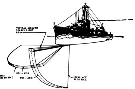
Figure 9-12 -Typical QDA, normal azimuth, and MCC
azimuth sonar beams.
stabilization injected into the sonar equipments.
Figure 9-12 shows the sound beams used in a
complete stabilized sonar system. In practice,
the edges of the beams are not sharp lines as shown.
The normal azimuth beam, shown in figure 9-12
as a half-round pencil, is employed during search
and while closing the target. If the target is deep,
the normal azimuth beam passes above it except
at long ranges. Thus the operator can use the
maintenance of close contact (MCC) feature for target s at close range. The MCC beam used in this
system is approximately the same width in the
horizontal direction as the normal azimuth beam,
but the MCC beam extends over most of the
quadrant from the surface downward. Although
the MCC beam is inefficient for use at long ranges,
at short ranges the echo strength increases sufficiently to permit the azimuth equipment to maintain contact and to determine range and bearing
practically up to the point of passing over the
target.
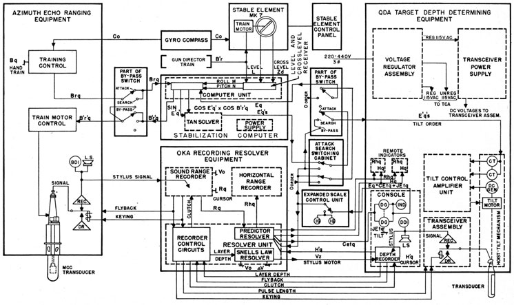
Figure 9-13 illustrates the interflow of functions
between the units comprising a complete stabilized
sonar system. The system illustrated comprises
the QDA, QHB, and OKA, and is one of the systems in use today. The input to the system is in
the form of level and crosslevel angles, and, therefore, the computer is equipped with a level and
crosslevel receiver, which must first convert these
angles to roll and pitch in order for them to be
used in the computer. Note the by-pass switch
which, when thrown to the search position, allows
the azimuth sonar to receive stabilization signals,
but the depth-determining equipment is unstabilized. In the attack position both of the equipments are stabilized.
The principal functions of the stabilization computer are:
1. To convert the angles of level, L, and cross-level, Zd, which exist when the stable element is
trained away from 0 relative bearing, to angles of
roll, M, and pitch, N. The information obtained
from this conversion can be used to stabilize the
sonar system, which is not usually on the same
bearing as stable element train, B'r. In some systems the stable element has its B'r input locked on
zero. In this case its output is in roll, M, and
pitch, N, directly, thus eliminating the need for
this function of the computer.
2. To combine roll and pitch with the relative
sonar target bearing in the horizontal plane Brq, to
produce B'r'q, the relative bearing in the deck
plane, in order to maintain the azimuth transducer
on the same true bearing and hence counteract the
tendency for roll and pitch to carry the beam to
one side or the other.
3. To combine roll, pitch, and relative sonar target bearing, Brq, with the depression of the beam
relative to the horizon, in order to compute E'q',
the beam depression relative to the deck.
The order, E'q', is the correct tilt angle for all
phases of ship roll and pitch of a depth transducer
which is trained on the target, as is the case in a
three-axis system. E'q' is also the correct depression of that portion of the broad QDA beam which
extends along the bearing of the target.
Tangent Solver
If the target lies dead ahead, the order, E'q', is
the correct order to which to tilt the QDA transducer to contact the target for any phase of ship
roll or pitch. If the target bears off the bow,
however, the QDA transducer must be tilted to a
somewhat greater angle than E'q' in order to
contact the target because for any position of the
transducer, the beam depression is greatest dead
ahead, and is less for bearings off the bow. If the
beam were broad enough, the depression of the
portions of the beam that extend athwartships
would be zero; that is, the beam would lie along the
193
Figure 9-13. -Block diagram of a stabilized sonar system.
194
surface at 090 and 270 relative. If the transducer
were tilted to 10°, the beam in the forward direction would be depressed 10°, while the portion of
the beam extending along a bearing of 045 relative
would be depressed only about 7°.
The tilt order, E'q's, produced in the tangent
solver is conveyed through the attack search
switching cabinet and by-pass switch to the CT
synchros which are mechanically geared to the
shaft of the hoist-tilt mechanism in the QDA. If
the transducer is not in the position represented
by the order E'q's, the rotors of the CT synchros
will not be oriented properly with respect to the
fields produced by the order signal. As a result,
a voltage is delivered by the CT synchro rotors to
the tilt-control amplifier unit, which drive the
system in the proper direction to align it with the
order, E'q's.
Conclusion
In short, the heart of the stabilized sonar system
is the computer, which receives stabilizing inputs
from the stable element. The stable element uses
either the main director train or the fore-and-aft
axis of the ship as its reference. The computer
converts these stabilizing inputs into the proper
voltages to be used with the stabilized sonar system, which is usually on a different reference axis.
The computer also supplies stabilizing information
to different units of equipment, such as
searchlights, radar systems, torpedo tubes, and guns, as
required by the ship.
As the ship rolls and pitches the stable element
measures the angles of deviation from the true
horizontal. The computer then converts these
angles into level and crosslevel signals to be added
to the angles of depression and train, which are
generated in the sonar system. The result is that
the lines or planes of sound remain stable and on
the target regardless of the gyrations of the ship.