The transmitters used in sonar are conventional
amplifiers operating in the low radio-frequency
range. In sonars of recent design, the signal to be
transmitted is generated in the unicontrol oscillator system at the desired frequency and then
delivered to the input of the intermediate power
amplifier of the transmitter. In the transmitter
this signal is amplified to the desired power level
and then delivered to the transducer.
In some of the older searchlight equipments that
are still in use the unicontrol oscillator system is
not used. In these equipments a master oscillator
associated with the transmitter develops the signal
at the frequency used in transmission. An example of this system is the model QGB.
In scanning systems a peak-power method of
transmission is used to deliver the necessary high
energy required to ensure that the power radiated
in all directions is equal to the power radiated by
a searchlight type of equipment along its selected
bearing.
QGB Transmitter Power Amplifier
The circuit of the QGB transmission system
comprises a master oscillator and a push-pull
power amplifier. This combination (figure 8-1)
is capable of delivering 400 watts of power at the
frequency determined by the oscillator, which
ranges from 17 to 27 kc.
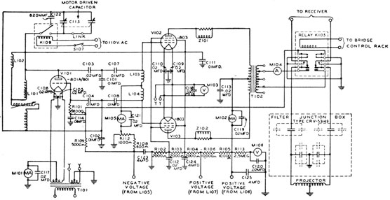
Tuning is accomplished by the tank coil variometer, L101. This inductance, in conjunction
with capacitors C101, C102, C103, and C122,
determines the output frequency. Under some
operating conditions it is desirable to "sweep" the
oscillator frequency to provide a more easily
distinguishable note.
A motor-driven variable capacitor, C115, is substituted for C122 in order to accomplish this
sweeping. This variable capacitor is connected in
the tuning circuit by switch 5107, which energizes
relay K109. Under normal operating conditions
switch S802, located on the control console, also
accomplishes this purpose.
The master oscillator, V101, is capacity-coupled
to the power amplifier. The power-amplifier
stage, V102 and V103, is coupled to the projector
by means of a special high-frequency transformer,
T102, which operates efficiently over the tuning
range of the oscillator.
2392700-53-12
The transformer, T102, is of the closed-core
type, which with adequate external shielding,
minimizes the induction field that might otherwise
cause interference with other services. The use
of pentode amplifiers results in an economical tube
complement because of low-drive requirements.
The resistance-choke combinations, Z101 and
Z102, in the plate leads of the output tubes, serve
as parasitic suppressors. The output-transformer
secondary circuit is fixed-tuned and couples energy
from the power amplifier to the projector, through
contacts of keying relay K105 and the filter junction box. The fixed capacitors of the filter junction box tune out the inductive reactance of the
projector and the leakage reactance of the output
transformer. The only adjustment required in the
output circuit is the selection of the proper capacitors in the filter junction box for the particular
projector selected.
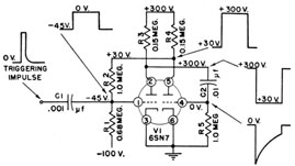
The master oscillator tube is biased below the
cut-off point, and normally the power-amplifier
tubes are likewise biased. Keying is accomplished
by means of relay K105. One of its contacts
short-circuits the master oscillator bias supply,
thus allowing the tube to function. The output of
the master oscillator is sufficient to overcome the
173
Figure 8-1. -Simplified diagram of transmitter and output circuit.
cut-off bias of the class-C power-amplifier tubes,
allowing them to conduct. Keying relay K105 is
controlled from the keying unit located in the
bridge control rack.
In addition to removing the blocking bias from
the master oscillator, the keying relay connects the
projector (filter junction box) to the transmitter
during its period of operation. When the driver
is not delivering power the keying relay connects
the projector leads to the receiver. During transmission of the signal impulse, the receiver is disconnected from the projector, and its input is
grounded to protect it from the high energy in the
projector circuit.
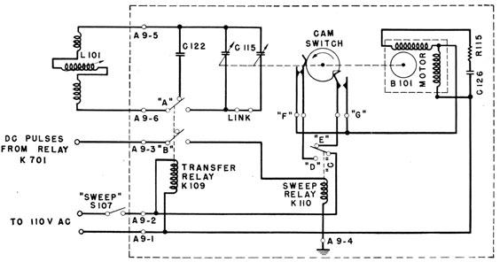
The sweep-frequency modulator (figure 8-2)
contains (1) a variable capacitor, C115, which is
rotated by an "Alnico" type motor, B101; (2) a
fixed capacitor, C122; and (3) a motor capacitor,
C126, and resistor, R115, which are associated
with the operation of the motor. The motor
starts quickly, and when power is removed, the
rotor generates a current in the windings. This
self-generated current provides electric braking.
A cam-operated switch is mounted on the end
plate of the variable capacitor. The cam is
attached to the capacitor shaft and rotates as the
rotor plates of the capacitor are rotated. This
cam actuates two separate pairs of contacts, which
complete the a-c circuit of the motor. These
contacts keep the motor energized until the
capacitor has rotated one complete revolution, so
that the plates are fully meshed, or are at maximum capacity, at the time of starting. Positioning the plates in this manner permits the capacitor
to rotate from maximum-capacity to minimum-capacity position coincident with the start and
finish of each oscillator pulse.
This variable capacitor causes the oscillator
frequency to sweep from approximately 400 cycles
per second below to 1,600 cycles per second above
the unswept frequency of the oscillator-that is,
the frequency at which it operates with the sweep-frequency modulator off.
On becoming energized, sweep relay K110,
closes contacts C and D. This action completes
the a-c circuit to the motor through contacts F of
the cam-operated switch. The completion of this
circuit causes the motor to operate and rotate the
variable capacitor and the operating cam of
switches F and G. Because of its shape, the cam
causes limit switch G to close its contacts after the
cam has begun rotating. After a capacitor
rotation of 180°-or to the unmeshed position of
the capacitor-the cam causes limit switch F to
open and the motor stops if relay K110 has not
been de-energized. Relay K110 is energized by d-c
pulses received through the keying relay. These
pulses have a definite duration followed by an
174
Figure 8-2. -Sweep-frequency modulator.
"off" interval. During the "off" interval, the
relay is de-energized, causing contacts CD to open
and CE to close. The a-c circuit to the motor is
completed again, this time through the closed
contact G of the cam switch and the CE contact of
sweep relay K110. The motor rotates the
capacitor and cam another 180° to the starting
point of maximum capacity at which time contact
G of the cam switch opens and the motor stops.
cam switch F is closed and ready for the next
keying impulse that energizes K110, causing the
motor circuit to close through contacts CD and F.
Under normal keying conditions the "sweep" is
energized momentarily and the sweep capacitor
rotates 360° before stopping. The cycle then
repeats the next time the equipment is keyed.
QHB Transmitter
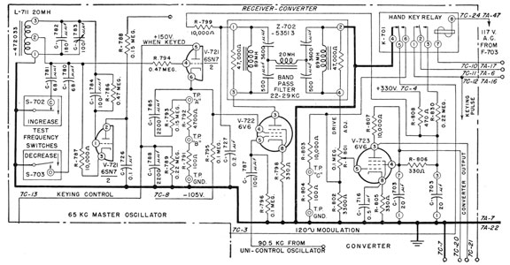
The receiver converter of the QHB is used for transmitting and receiving. During transmission it provides both the circuit for producing the signal frequency to be transmitted and the circuits to provide the keying. The 65-kc master oscillator, one-half of V721 (figure 8-3), is the basis of the unicontrol oscillator system, and its frequency is fixed at the center frequency of the i-f stages in the receiver to ensure correct operation. The keying pulse on the plate of the electronic switch, the other half of V721, places the 65-kc signal on the screen grid of mixer V722. The control grid of the mixer is being supplied with a continuous signal of about 90 kc from the unicontrol oscillator. Oil the plate of the mixer are the usual components of heterodyning. A hand-pass filter with a range of from 22 to 29 kc selects the correct component and passes it to the grid of power-output tube
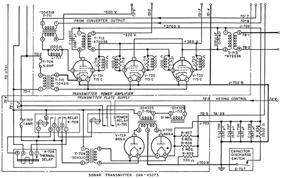
V723. This tube develops, at the desired level, the excitation for the transmitter intermediate power amplifier, V731 (figure 8-4) which it drives through T711. The QHB transmitter employs a pulse-type amplifier that uses three type-715C beam power tetrodes-two in parallel for the output stage and one as a driver.
The high-voltage d-c supply for the anodes of these tubes in pulse operation has a storage capacity that prevents too rapid a decay of the voltage during transmission and the rectifier tubes V729 and V730 provide a recovery rate adequate to maintain the desired operating values of d-r voltage. The storage is provided by a group of capacitors totaling 60 microfarads. These capacitors are charged to a nominal value of 3,700 volts when the equipment is in the listen position and therefore not keying. When the equipment is
175
Figure 8-3.-Converter circuit.
echo ranging, the drop in d-c voltage as well as the energy delivered to the transducer during the 35millisecond transmitting period depends on the converter gain adjustment.
The value to which the d-c voltage rises during recovery depends on the keying interval and is fixed by circuit constants. With a converter gain adjustment such that the attenuation from beginning to end of the pulse is 4 db, the power, when the 3,750-yard keying interval is used, has a peak value of 7.2 kw and an average value of 6 kw.
When the converter gain adjustment is greater or less than was just mentioned then both the pulse attenuation and the power output will be respectively greater or less than the above values. With the gain adjusted for 4 db pulse attenuation, the 3,750-yard keying interval results in a d-c voltage decay of from 3,620 to 2,600 volts, whereas the 1,500-yard keying interval results in a decay of from 3,400 to 2,500 volts.
In order to provide a maximum rate of recovery within the peak-current limit of the rectifier tubes and to maintain a minimum power drain on the system, peak-current limiting is accomplished by an a-c reactor, L715, in the primary circuit of the rectifier transformer. Under conditions corresponding to a short circuit on the rectifier, this
reactor, aided by the leakage reactance of the transformer, limits the primary current to a value of 9 amperes. The recovery rate is then such that, for a normal drive and a d-c voltage of 3,700 volts with no keying, a value of 3,620 volts is reached at the 3,750-yard keying interval and a value of 3,400 volts at the 1,500-yard keying interval.
A voltage pulse that is at the desired transmission frequency and that has a value of approximately 100 volts rms is produced across the primary of T711 by converter amplifier V723 (figure 8-3). The 100-volt pulse is raised to a value of 150 volts by this transformer to serve as the grid signal for driver tube V731. The plate load on this tube consists of air-core transformer T712, tuned by C800 to the center transmission frequency of the QHB equipment, and its step-down ratio provides the grid signal for the output tubes at an impedance level that ensures adequate grid drive.
The output stage, employing V732 and V733 in parallel, has as its plate load the air-core output transformer, T713, which is identical with T712 and is tuned by C801. The secondary of this transformer supplies the transmitter output pulse to the transducer circuit at an impedance level of 50 ohms.
176
Figure 8-4.-Transmitter power-amplifier circuit.
Keying Methods
For any mode of keying, the electronic circuits that control the events must be actuated. These circuits are called keying circuits and may be put into action by the momentary closing of a switch, or they may be self-contained and controlled by an RC circuit.
These circuits and their applications are illustrated by the following discussion of the keying control circuits of the model QHB scanning sonar equipment.
KEYING CONTROL CIRCUITS
Four basic synchronized functions are performed by the keying circuits of the QHB sonar indicator control cabinet-
1. To collapse the sweep potentials of the cathode-ray indicator to start each new sweep cycle.
2. To produce a periodic adjustable-length pulse capable of controlling the transmitter output to the transducer.
3. To cause an automatic appearance of the cursor during each recycling interval.
4. To provide suitable blanking of the cathode-ray tube indicators. This function is accomplished during the recycling interval to eliminate spurious screen traces.
Three similar pulse-generating circuits of the one-shot multivibrator variety are used to produce various control pulses of definite length. Figure 8-5 shows a typical schematic of the circuit with examples of the pulses that occur at various points. The d-c electrode potentials indicated are steady-state values for the stable condition of the circuit. The duration of the generated pulse depends mainly on the time constant of C2 and R5.
Three methods of triggering these circuits are used. A positive pulse of short duration is capacitively coupled to the control grid (pin 1) of the twin triode, or a negative pulse of short duration is capacitively coupled to the control grid (pin 4). Each of these methods produces a blocking pulse
177
Figure 8-5 -Simplified trigger circuit.
with a duration determined by the natural period
of the trigger circuit. In the third method a negative potential is coupled directly to the control
grid (pin 4) of the twin triode to hold the circuit
in the triggered condition as long as desired.
In general, small transients in either the positive
or the negative power supplies of a trigger circuit
of this type may cause instability and undesired
pulsing, particularly if the transients are steep-fronted. If regulated sources are provided for
both power supplies of the trigger circuit and if an
adequate bias of at least twice cut-off is used for
the nonconducting triode, a stable circuit that can
be positively controlled is obtained.
PRIMARY KEYING PULSE
A primary control pulse suitable for triggering
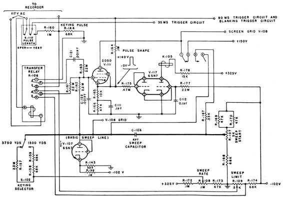
the various circuits at required intervals is obtained by periodic firing of thyratron V111, a 2050-type tube (figure 8-6). Anode voltage of +150
volts is applied through the normally closed contacts (pins 1 and 2) of the sweep relay, K105, and
the cathode is connected to ground through R165
and R166 in series. Firing of the tube is controlled
by its grid voltage, which is derived from two
sources-an automatically variable component and
a calibrating component.
Figure 8-6. -Primary keying-pulse circuit.
178
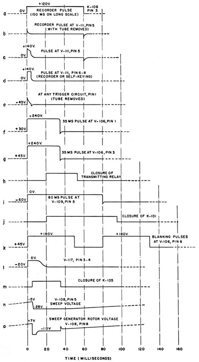
Figure 8-7 -Pulse diagrams.
179
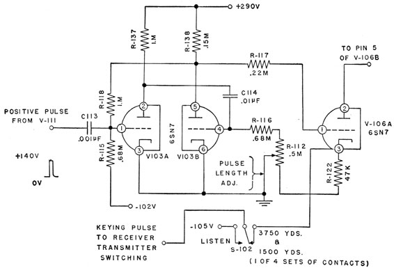
Figure 8-8. -35-millisecond trigger circuit.
The variable component is the sweep-control
voltage at the sweep capacitor, C106, which swings
from -28 volts to -5 volts during the sweep cycle.
This potential is coupled to the grid of the pulse-generator tube, Viii, by an isolating resistor,
R162. The calibrating component is derived at
the sweep-limit potentiometer, R109, which is part
of a voltage divider on the negative 102-volt line.
The range of the calibrating voltage is from about
zero to -7 volts. This voltage is connected to
the control grid of the pulse-generator tube, V111.
The calibrating voltage sets the firing point of the
pulse-generator tube so that the sweep-voltage
component corresponding to the maximum range
of the screen of the cathode-ray tube causes the
pulse-generator tube to conduct. The cathode
potential of the pulse-generator tube increases
immediately from zero to about +140 volts. This
voltage increase is coupled by means of a resistor,
R175, and the diode-connected section of the recycling tube, V117, to the control grid (pin 4) of
V117, where it overcomes the 20-volt negative bias
and causes the triode to conduct. The 20-volt
negative bias is caused by another voltage-divider
network between the -102 volt line and ground
that includes R177, the diode connected section of
V117, R175, R165, and R166. The conduction of
the triode section of V117 causes the sweep relay,
K105, in its plate circuit, to operate.
Contacts 1 and 2 interrupt the anode supply of
the pulse-generator tube and extinguish the tube,
while contacts 5 and 6 close and discharge the
sweep capacitor, C106, reducing the control-grid
voltage at the pulse-generator tube to about -28
volts. The sweep relay, K105, holds in until CI12
becomes negatively charged through R177 to a
magnitude such that the triode current reaches the
drop-out value for the relay. Upon being restored
to normal, the sweep relay, K105, reapplies anode
voltage to the pulse-generator tube, and the sweep
capacitor begins its new charging cycle. diagrams l, m, and n of figure 8-7 show these relations.
The pulse (diagram d, figure 8-7) of +140 volts
at the cathode of the pulse-generator tube is the
180
primary keying pulse used as a control to trigger
other keying circuits. Capacitor C111 between
the junction of R165 and R166 and ground, in the
cathode circuit of the pulse-generator tube, delays
the pulse decay slightly so that the magnitude of
the negative kick is reduced when the primary
pulse is capacitively coupled to the circuits it controls. Diagram e of figure 8-7, shows the triggering impulse as it appears at the control grid (pin 1)
of any trigger circuit with the tube removed from
its socket.
TRANSMITTER KEYING PULSE
The positive pulse that actuates the keying
relay through the keying-relay tube is generated
in the 35-millisecond trigger circuit (figure 8-8).
The primary control pulse initiates the cycle of
this one-shot multivibrator. The duration of the
pulse generated in this circuit is controllable by
variation of potentiometer R112. The positive
pulse generated at the anode (pin 5) of the twin
triode, V103, is coupled to the keying-relay circuit
by way of V106A, connected as a cathode follower.
This cathode follower transmits the pulse to the
contacts of keying selector switch S102. When
thrown to the listen position, the keying selector
switch, 5102, connects the external keying line to
-105 volts. Diagram f of figure 8-7 shows the
outgoing transmitter-control pulse that causes the
transmitter to operate. During the 20-millisecond pull-in time of K101 the blanking trigger
circuit blanks the cathode-ray tubes.
DEFLECTION-TRANSFER KEYING OF THE
CATHODE-RAY TUBE
The 80-millisecond trigger circuit generates the
controlling pulse for V109, a triode-connected 6Y6,
which has the coil of the deflection-transfer relay,
K101, in its anode circuit (figure 8-9). The
primary keying pulse initiates the cycle of this
one-shot multivibrator, V104. Each time the
sweep circuit is recycled the signal source for the
deflection coils of the cathode-ray tube is transferred from spiral sweep to cursor deflection by
operation of K101. Diagram i of figure 8-7
shows the pulse at the control grid of V109 (pin 5),
and diagram j indicates typical operation of the
deflection-transfer relay. The cursor is a radial
line of variable length under the control of a
range-calibrated potentiometer.
Manual production of the cursor at any time
for any desired interval involves holding in the
deflection-transfer relay, K101, for that interval.
To hold it in, an a-c-operated relay (cursor hold),
K104 interrupts the primary keying pulse and
grounds the grid circuit so as to allow normal
cycling of sweep and transmitter while this circuit
is manually operated.
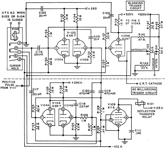
CATHODE-RAY TUBE BLANKING PULSES
Each time the transmitter is energized and while
the deflection-transfer relay is closing, the cathode-ray tube must be blanked The 50-millisecond
trigger circuit, V105, generates the controlling
pulse for V106 which has its cathode connected
directly to the cathode circuits of the cathode-ray
tube. The primary keying pulse initiates the
first cycle of this trigger circuit, which is a one-shot
multivibrator. The operating level of the V106
cathode is determined by the intensity control
(R103) setting, and the blanking pulse momentarily drives the cathode positive to cut off the
electron beam in each cathode-ray tube. In
diagrams j, k, and i of figure 8-7 the first blanking
pulse starts at zero time with the other trigger
pulses. The deflection-transfer relay is closed
about 20 milliseconds later while the tubes are
blanked. At 50 milliseconds, because the first
blanking pulse is over, the cursor is allowed to
appear on the screen. At the end of the 80-millisecond pulse the negative swing at the anode (pin
5) of V104 is coupled to the grid (pin 4) of V105,
causing it to conduct for a second blanking pulse,
which begins immediately. The deflection-transfer relay drops out about 15 milliseconds later
while the tubes are blanked, and the blanking
pulse ends after its natural 50-millisecond period,
thus restoring the spiral sweep for video-signal
indication.
The same cycle takes place when the cursor is
produced manually by operation of the cursor-bold relay except that the primary keying pulse is
disconnected from the control grid (pin 1) of the
blanking trigger tube, V105, which is in the 80-millisecond circuit. The first blanking pulse is
caused by coupling a negative firing impulse
through C120 to the control grid (pin 4) of the
blanking-trigger tube. The cursor appears at
the end of this first blanking pulse and stays on the
screen as long as the cursor-hold relay is
181
Figure 8-9. -80-millisecond and blanking trigger circuits.
energized. Upon the release of the cursor-hold relay,
the 80-millisecond trigger tube is restored to
normal and the negative swing at the anode is
coupled to the control grid of the blanking-trigger
tube to produce the second blanking pulse exactly
as in automatic operation.
When the cursor is being held, the potential of
-102 volts at pin 5 of the cursor-hold relay K104,
is coupled to the junction of the cursor-intensity
voltage divider so as to reduce the potential of
the cursor-intensity control line so that the apparent brilliance of the cursor is about the same
when it is held as when it appears automatically
for only two cycles.
EXTERNAL KEYING
The external keying of the equipment by e range
recorder involves (1) automatic operation of the
a-c keying transfer relay, K106, by a single-phase
potential from the external keying device and
(2) coupling of its keying pulse to the control grid
of the pulse-generator tube, V111, to trigger all
the keying circuits (figure 8-6). The keying
pulse line, connected to pin 3 of the keying transfer relay, is loaded down by R144 in order to
reduce its impedance and make it somewhat less
susceptible to transient voltages. When the keying transfer relay, K106, is operated, the external
182
keying pulse is capacitively coupled to the control grid of the pulse-generator tube, V111.
Diagrams a and b of figure 8-7 are typical.
Capacitor C122 from the grid to ground and
series resistor R163 filter out high-frequency components, which tend to cause promiscuous triggering of the pulse-generator tube.
Pin 5 of the keying transfer relay, K106, transfers the grid-circuit reference potential from its
normal sweep-limit value to pin 6, where a slightly
greater negative value is obtained from the junction of R174 and R109. This value of sweep
limit represents a sweep deflection beyond scale
limits and beyond the limiting value set up in the
right-hand diode section of V107, so that in the
absence of an external pulse the sweep progresses
to an off-screen position and stays there until the
next external keying pulse.
Transmission Circuits
Transmission circuits include a converter, a
power amplifier with associated power supplies,
and transmit-receive switching circuits. The
converter, as part of the unicontrol oscillator
system, produces a voltage pulse at the frequency
desired for transmission. This pulse is delivered
to the transmitter power amplifier and results in
the signal pulse for energizing the transducer.
The transmit-receive switching involves those
circuits necessary for (1) connecting the transducer to the power amplifier for transmitting, and
(2) subsequently connecting the transducer to the
receiver for listening. Included are the components and connections for maintenance of close
contact (MCC) transmission.
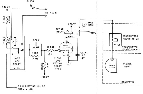
For any mode of keying, the electronic switch
V721B in the converter (figure 8-3) conducts by
application of +150 volts to its anode upon closure
of keying relay K401 (figure 8-10). V721A (figure
8-3) is the 65-kc master oscillator, which is operating at all times and which applies a voltage at
this frequency to the control grid of the electronic-switch section. The electronic switch is a cathode
follower with its cathode tied to the -105-volt
line through a 0.1-megohm resistor. The signal
developed across this resistor when the switch is
conducting is tied to the screen grid of mixer V722.
When the switch is not conducting, -105 volts
appears on the screen grid of mixer V722 and
prevents it from conducting.
During automatic keying, the pulse of +140
volts originating in the 35-millisecond trigger
circuit is connected to the grid of V452, the keying-relay tube. While this pulse is incident on the
grid of V452 the keying relay, K401, in its anode
circuit is closed. For hand-key operation the
circuit is switched so that the positive pulse for the
grid of V452 is supplied by hand-key relay K701,
which closes each time the hand key is closed.
This relay further supplies a 120-cycle modulation
to the converter power-output tube, V723. The
magnitude of this modulation is such that the
output is zero for an appreciable portion of each
cycle, thus reducing the power dissipation in the
transmitter tubes (figure 8-3). The detailed
operation of the converter circuit has been explained in a preceding part of this chapter.
Unicontrol Oscillator System
The QHB unicontrol oscillator system has been
explained briefly in connection with the QHB
receiver, in chapter 7. The purpose of this system
is to resonate both the transmitter and the receiver
to the same frequency with a single tuning control.
The principle of operation of the unicontrol
oscillator system is based on the use of two independent oscillators. One of these, known as a
master oscillator, is designed to operate on a fixed
frequency. This frequency is the center frequency
of the i-f stages. The other oscillator is the unicontrol oscillator. It is designed to tune over a
band of frequencies.
The outputs of these oscillators are heterodyned
in a converter, and the usual products of heterodyning are present in the converter output. A
band-pass filter selects the correct frequency, which
is then coupled to the intermediate power amplifier
of the transmitter. The output of the unicontrol
oscillator also is coupled to the mixer in the
receiver.
To understand the functioning of the system,
assume the following case. An echo-ranging
equipment is designed to operate over a frequency
band of from 22 to 29 kc with the optimum performance of the transducer at 25 kc. The i-f
183
transformers are tuned to 65 kc. With these
conditions the frequency of the master oscillator
is fixed at 65 kc-the frequency of the intermediate frequency-whereas the unicontrol oscillator is tunable from 87 kc to 94 kc.
When the outputs of these oscillators are
heterodyned in the converter the frequencies in
the output of the converter are (1) the frequencies
of each oscillator, (2) the sum of their frequencies,
and (3) the difference of their frequencies. As
the difference frequency is the one desired, the
output filter is designed to pass only those frequencies that are between 22 and 29 kc. The
difference frequency at the proper power level is
then delivered to the transmitter.
The frequency-response characteristics of the
transducer are fixed by design. Because the equipment should operate at the optimum response
frequency of the transducer, the unicontrol oscillator
is tuned so that when it is heterodyned with the
65-kc master oscillator the difference frequency is
at the optimum response of the transducer.
Assume that the optimum frequency of the transducer is 25 kc. In this case, the unicontrol
oscillator is tuned to 90 kc so that when it is
heterodyned with the 65-kc master oscillator the
difference frequency is 25 kc.
The output of the unicontrol oscillator is
coupled also to the receiver and is present in the
mixer at all times. When an echo signal at 25 kc
arrives at the mixer it is heterodyned with the 90
kc from the unicontrol oscillator, and again the
difference frequency is the one that is desired.
The difference frequency in this case is 65 kc,
which is the frequency of the i-f stages.
Figure 8-10. -Keying-relay circuit for the scanning-switch assembly.