The model OKA-1 sonar resolving equipment is
designed for use with echo-ranging and depth-determining equipments. Its primary function is
to calculate and record the horizontal range of a
sonar target. This calculation is based on sonar
range and target depth-factors that are determined graphically by separately recording the
acoustic outputs of the azimuth echo-ranging and
depth-determining equipments. The range recorder
is a unit of the OKA-1 equipment, and the depth
recorder is a unit of the depth-determining equipment. Calculating circuits of the OKA-1, however, provide all the electric controls to the depth
recorder. This design ensures that the indications
of the depth recorder accurately represent target
depth.
One function of the OKA-1, derived from the
requirement of the calculation of horizontal range,
is prediction of the angle of depression to the
sonar target. This prediction provides a form of
aided tracking to the depression controls of the
depth-determining equipment. It must be emphasized that the OKA-1 equipment is not concerned with the primary task of sound transmission or reception, and the accuracy of its performance depends directly on the validity of the
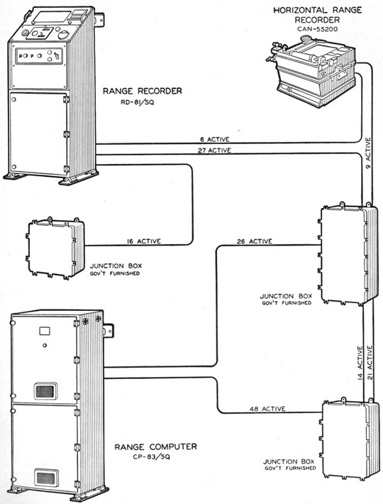
information obtainable from the primary equipments. See figure 10-1 for a pictorial diagram of
the OKA-1 equipment.
THEORY OF SOUND AS APPLIED TO THE
OKA-1
In order to understand the operation of the
OKA-1 equipment, certain elements of the physical theory of sound transmission must be
thoroughly understood. Because rigorous adherence to theory would make the calculations
excessively complex, certain simplifying assumptions are made in the solving circuits. The
validity of these assumptions under all circumstances is beyond the scope of this text.
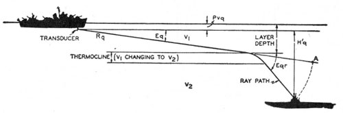
The velocity of sound in sea water is affected
by salinity, pressure, and water temperature. If a
sound ray passes at a small angle through layers
of water in which these factors are altered (figure
10-2), bending or refraction of the sound ray occurs,
in accordance with a relationship known as
Snell's law-
(V-ΔV)/V cos Eq= cos Eqr, (10-1)
where V is the velocity of sound in the first layer,
ΔV is the velocity change in adjacent layer, Eq is
the angle of ray in first layer with respect to
boundary between layers (which may be considered a plane parallel to the surface of the ocean),
and Eqr is the angle of ray in second layer with
respect to the plane of the layer.
The principal variable affecting the velocity of
sound is the temperature of the water. Temperature may be determined to great depth by use of
the bathythermograph. If certain assumptions
concerning salinity are made, the velocity of
sound at any depth may be calculated from the
bathythermograph record.
Under most conditions the bathythermograph
indicates a layer of water of nearly constant temperature from the surface down to an appreciable
depth. This layer is known as the mixed layer.
Below this mixed layer the temperature falls
rapidly through a region known as the thermocline
and then again changes relatively slowly. A
sound beam that is narrow in the vertical dimension if directed at a small downward angle with
respect to the surface of the ocean passes through
the mixed layer without bending, because the
velocity is constant. In passing through the
thermocline, it undergoes marked refraction and,
196
Figure 10-1 -OKA-1 equipment.
197
Figure 10-2 -Sound-ray refraction.
because sound velocity decreases with decreasing
temperature, the ray is directed downward at a
greater angle to the surface. If a sonar target
lies below the thermocline, echoes can be obtained
at long range-when the depression angle is
small-only from sound rays which would pass
well above the target if there were no refraction.
Positive temperature gradients result in upward
deflection of the sound ray, but they are rare in
most ocean areas. It is also somewhat common
to find almost continuously decreasing temperature
from the surface down. Thus, the ray is continuously passing from a layer of higher velocity
to a layer of lower velocity.
Figure 10-2 illustrates the various angles and
factors in sound-ray refraction affecting the
OKA-1. Not only the mixed layer but also the
water below the thermocline are assumed to be
isothermal. The sound-ray path is curvilinear in
the thermocline, where sound does not travel at
constant velocity. The first of the fundamental
assumptions made in the equipment is concerned
with this fact. Range is measured by a recording
stylus, which keys the sound transmitter at its
zero position and traverses a recording chart at
constant speed proportional to the average velocity
of sound. If this speed is proportional to the
velocity of sound, the distance of an echo trace on
the chart from the zero point may be defined as
range.
A suitable adjustment in the recording equipment provides for setting the excursion rate of
this stylus to a particular sound velocity. If the
velocity selected is proportional to the velocity of
the ray, and if the ray path is a straight line, the
recorded range is correct. Because the ray path
is not a straight line, some compromise on how
to use the indication of the bathythermograph
must be made. This stylus speed adjustment is
a matter of basic doctrine formulated and disseminated to the fleet to ensure best results.
Figure 10-2 shows that the distance from the
echo-ranging transducer to the target may be
appreciably less than the distance along the
sound-ray path. Because no compensation is
provided for this error, the recorded range is
incorrect in an amount dependent on the magnitude of the temperature gradient.
Figure 10-2 shows the error that refraction can
introduce in determining target depth. The
circuits of the OKA-1 equipment deliver to the
recorder stylus motor of the depth-determining
equipment a frequency proportional to the velocity
of sound times the sine of Eq. This expression
may be termed Vz, the vertical component of the
velocity of sound. The angle Eq is determined
by the depth-determining equipment and may be
defined as the angle of depression of the center of
the acoustic beam with respect to the surface,
measured in a vertical plane through the line of
sight to the sonar target. The recorder stylus
speed is therefore proportional to Vz, and the
position of an echo trace across the depth-recorder
chart depends on the stylus speed and the time for
the echo to return. If refraction were neglected,
the stylus speed and time of arrival of the echo
would lead to the conclusion that the target was
at position A and that the target depth was
therefore Rq sin Eq, where Rq is the sound range.
If the value of Eqr is appreciably different from
that of Eq, it is evident that a notable error will
be made from this assumption.
The circuits of the OKA-1 equipment and the
depth recorder of the depth-determining equipment provide a measure of compensation for such
errors. A solving circuit continuously computes
the refracted depression angle, Eqr, by means of
an adjustment made on the basis of the velocity
change indicated by the bathythermograph. This
relation is governed by Snell's law, the velocity
change being V1-V2. To make the speed of the
depth-recorder stylus proportional to the vertical
component of the velocity of sound after refraction,
it is necessary only to substitute the angle Eqr for
the angle Eq in the frequency-determination circuit. This change must occur, however, when the
sound ray has reached a depth equal to that of the
mixed layer. Regardless of the magnitude of Eq,
the change in speed should occur when the recorder stylus reaches a point on the chart that is
equal to the layer depth. Change-over of control
between angles Eq and Eqr is accomplished by
198
placing a contact device in the path of the depth-recorder stylus. The contact device is adjustable
along its traverse. These contacts actuate a relay
in the OKA-1 equipment, which selects the angle,
Eqr, for the rest of the recorder excursion.
The accuracy of correction provided by the
circuit described varies appreciably, depending on
water conditions. This situation creates a complex problem, and the adjustment of the refraction
controls cannot be set forth on a purely theoretical
basis. The refraction adjustments are important
features of the fleet doctrine that relates the
bathythermograph to the sonar installations.
After several echoes have been obtained on the
depth recorder, it may be assumed that a valid
indication of target depth is available, if the refraction compensations are reasonably correct.
Target depth below the depth-determining transducer, H'q, and target range-which is based on
the assumption that sound range, Rq, measured by
the range-recording device is correct-are therefore available for other calculations required of
the OKA-1 equipment. The angle, the sine of
which is the ratio of H'q to Rq, is determined by the
equipment and is defined as the computed target
depression angle (cEtq). At a late stage in a sonar
attack the target-depression angle may change
very rapidly, and this calculated angle is transmitted by synchro order to the depth-determining
equipment to provide aided tracking to the depression control of the depth-determining equipment.
As may be seen from figure 10-2 and from the
assumptions concerning Rq, this angle has no
physical reality until Eq becomes large and refraction is negligible. Fortunately, this is the
condition that exists when Eq must change
rapidly.
The angle cEtq is employed further in the circuits of the equipment to calculate the horizontal
target range, Rhq. The assumption is made that
the calculated depression angle is the true target-depression angle and that Rq is the target distance
along a straight line. The exact calculation is
Rhq=Rq cos cEtq. (10-2)
Figure 10-2 shows that, if refraction is appreciable,
the value calculated is not the distance across the
surface of the ocean to a point directly over the
target. With a temperature gradient, the calculated horizontal range always exceeds the actual
horizontal range.
SERVO SYSTEMS
The various angles and components of range
with which the OKA-1 equipment is concerned are
transmitted between its units and between other
equipments by synchro order. Consequently,
a large number of servo amplifiers are involved
in accepting these various orders. Additionally,
the solving circuits of the equipment are electro-mechanical systems positioned by servo action.
Finally, various motor drives such as those for
the range-recording stylus and depth-recording
stylus require adjustable constant speed. These
drives are effected by servo combinations which
may be called rate servos, because they accomplish mechanical rotation at a fixed rate, in contrast to the customary servo which accomplishes
mechanical rotation to a fixed position. In all,
there are 13 servo systems, which constitute the
major part of the OKA-1 equipment.
Because all of the servo systems can be grouped
into four classes, the basic theory of operation will
be explained for one example of each class. The
four classes of servo systems are: (1) Comparison
servo; (2) single-speed positioning servo; (3) dual-speed positioning servo; and (4) rate servo or integrator.
Servomotors
Two types of servomotors are employed in the
equipment. For systems in which the speed or
torque requirements are low, a 2-phase 60-cps
induction cup motor is employed. For all high-speed or high-torque applications, a 2-phase 60-cps squirrel-cage induction motor is employed.
This motor is also equipped with an induction cup
generator element mounted on the same shaft.
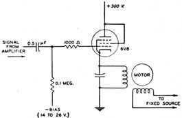
Figure 10-3 -Servo-amplifier power stage.
199
The generator is wound as a 2-phase device and
has the property of producing from one phase-if the other phase be excited by a 60-cps voltage-a signal proportional to the speed of the rotor and
to the degree of excitation of the other phase.
All servomotors in the equipment are driven by
a power stage which consists of a type 6V6 beam
power tube, triode-connected and arranged as a
cathode follower with one phase of the motor completing the circuit from cathode to ground. A
simplified diagram of a typical stage is shown in
figure 10-3. This phase of the motor is tuned by
a parallel capacitor, 2 μf, for the induction cup
motor and 5.7 μf for the squirrel-cage motor. The
other phase is excited by a reference voltage.
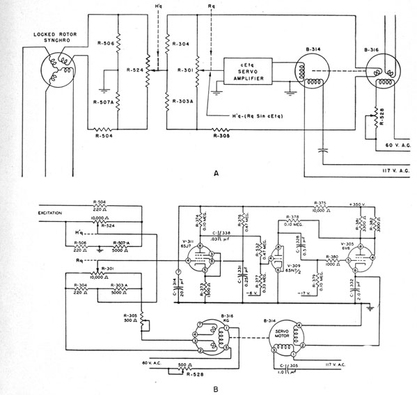
Comparison Servo System
The comparison servo system converts a signal
voltage into a mechanical rotation proportional to
the signal. An example of the comparison servo
is the cEtq servo system in the range computer.
Functional and schematic diagrams of the complete circuit are shown respectively in figure 10-4,
A and B. The mechanical part of the system
includes a miniature synchro or resolver, B-316,
which is driven by an induction cup motor, B-314.
The synchro rotor is excited by a fixed voltage
from a 60-volt transformer through a series potentiometer, R-528, which is used for adjusting the
phase of the synchro output voltage. The resolver, B-316, has the usual properties of synchros-namely, that the voltage of a particular
stator coil varies trigonometrically as the rotor
is turned. The resolver is positioned in the
mechanism in such a manner that the voltage of
the stator coil employed is zero when cEtq is zero
and increases directly with the sine of cEtq.
This voltage is applied through a series calibrating potentiometer, R-305, to a 10-revolution
helipot, R-301, which is located in the Rq gear
train. The helipot is a wound variable resistor
with its resistive element constructed in the form
of a helix and requires one or more turns to cover
its range. The arm of this helipot is positioned by
Rq. Because R-301 is at a position representing
Rq, and is excited by sin cEtq, the voltage available
at the arm is therefore Rq sin cEtq, which, by
definition, is H'q. In solving for cEtq, therefore,
it is necessary only to compare Rq sin cEtq voltage
with a voltage derived from H'q.
The H'q helipot, R-524, is located in the H'q
gear train. The arm of R-524 is positioned by H'q
and the excitation of R-524 is derived from a
locked rotor synchro similar to B-316. Across
the helipot, R-524, is a divider, consisting of R-506
and R-507nA, which provides a zero reference
point which is a short distance above the end of
the helipot instead of being at the extreme end of
travel. All helipots in the OKA-1 equipments
are used with a similar divider to provide a more
precise zero, and as a safety precaution. The
junction of the two divider resistors is connected
to ground, and is the ground reference for the
cEtq calculating circuit.
The excitation for R-524 is a fixed voltage, and
the arm of R-524 is positioned by H'q. Therefore,
the voltage available from the arm to the zero
reference point (ground) is, by definition, H'q.
The H'q voltage is combined with the Rq sin cEtq
voltage to obtain a difference signal for the cEtq
servo amplifier. A basic requirement of the system is that the voltages being compared be precisely in phase because a small phase difference
can result in a large phase-angle error in the
difference signal to the amplifier. This phase-angle error would seriously alter the normal quadrature phase relationship of the motor voltage
and the result would be a loss of motor torque and
overload of the motor amplifier. To ensure that
the voltages being compared are in phase, the
helipot excitation voltages are derived from similar
sources, and a phasing adjustment is provided for
precise phasing.
The fixed phase of the servomotor is connected
to the 117-volt source through a 1.0 capacitor,
providing a fixed-phase potential which leads the
excitation by approximately 90°. The phase of
the input signal to the amplifier is such that if this
signal is applied directly to the amplifier, the motor
voltages will be in quadrature.
The servomotor receives a control signal from
the output of a three stage resistance coupled
amplifier. The input stage is a pentode with
conventional screen bypass. The output of this
stage is coupled to the grid of a triode intermediate
driver which in turn supplies the control grid of
the final cathode follower. The over-all gain is
such that the voltage developed across the motor
is approximately 200 times that of the input signal.
The polarity of signals is determined by the fact
that the Rq sin cEtq, and the H'q signal must tend
to run the motor in a direction to increase cEtq.
When the two signals are equal, the difference
signal is zero and the motor remains at rest. Thus
the position of the cEtq gear train is determined by
the values of Rq and H'q.
Direct-current power supply for the cEtq servo
amplifier is obtained from a filter network which
decouples the amplifier from all other systems.
Single-Speed Positioning Servo System
The single-speed positioning servo system consists of a motor-driven synchro control transformer
with synchro orders from a remote transmitter
connected to the transformer stator. The stator
voltage produces in the rotor of the control transformer a voltage which varies in trigonometric
relation to the rotor position. The rotor voltage
201
Figure 10-5 -Positioning-servo schematic.
therefore passes through zero at two points separate d by 180° and has a phase for one-half of a
revolution opposite to that for the other half of a
revolution. Because the rotor voltage reverses
in phase upon passing through zero, the rotor
signal may be employed as the input to an amplifier which drives the servomotor in a direction
which reduces the control-transformer rotor signal
to zero. At this point the system remains at rest
until a change in the synchro order to the stator
is received.
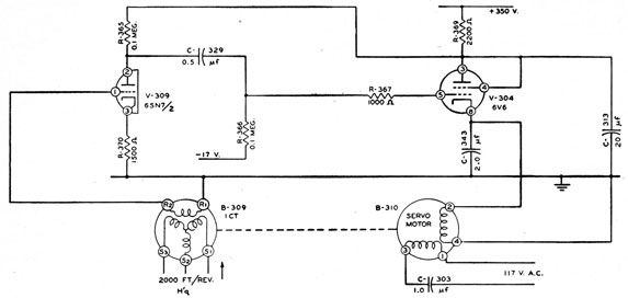
A suitable example of the single-speed positioning servo system is the H'q servo in the range computer. The complete circuit is shown in figure
10-5. This system has the function of causing
the H'q gear train in the range computer to assume
a position determined by the H'q transmitter in
the depth recorder of the depth-determining equipment. The order from the transmitter is connected to the stator of the 1CT control transformer
B-309. The system is driven by an induction cup
motor, B-310, the fixed phase of which is excited
from the 117-volt a-c source through a 1.0 μf
capacitor. This series capacitor causes the voltage applied to the reference winding to lead the
excitation voltage by 90°. The phase of the
control-transformer rotor signal is such that it can
be applied directly to the amplifier input tube with
the result that quadrature voltages are obtained
at the servomotor.
The amplifier is a conventional resistance-coupled amplifier with a triode input tube coupled
to a type 6V6 power tube which drives the variable
phase of the servomotor.
Dual-Speed Positioning Servo System
Where maximum precision is necessary in positioning a servomechanism, the dual-speed system
is employed. In such a system the controlling
synchro orders originate from a transmission system consisting of one synchro transmitter geared
to the system at a 1-to-1 or 2-to-1 ratio and a
second synchro transmitter geared to the system
at a 36-to-1 ratio. The controlled servomechanism is correspondingly arranged with two control
transformers, one geared at 1 to 1 or 2 to 1 and the
other at 36 to 1. It is a requirement of the
associated amplifier that the 1-speed control transformer govern the approximate position of the
system to within a few degrees and that the 36-speed control transformer govern the exact position. Because the gearing provides 10° of system
motion for one complete revolution of the 36-speed
control transformer, extreme accuracy of position
is obtainable.
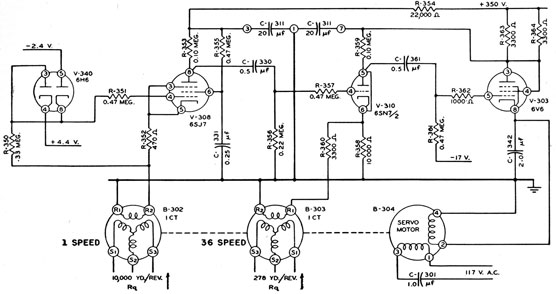
As an example of the dual-speed positioning
servo system, the system controlling the position
of the Rq gear train in the range computer will be
described. The complete circuit is shown in
figure 10-6. The control transformers B-302 and
B-303 are excited by Rq derived from transmitters in the range recorder of the OKA-1 equipment. The system is driven by an induction cup
motor, B-304.
The maximum rotor voltage from either control
transformer is 55 volts rms, and if the mechanism
is displaced from the synchro order by an angle θ,
the voltage from B-302, the 1-speed control transformer, is 55 sin θ, whereas the signal from B-303,
the 36-speed control transformer, is 55 sin 360.
To provide the accuracy attainable by means of
the 36-speed order, it is a requirement of the circuit that the 36-speed order take control as θ approaches zero. As θ increases from zero, the first
maximum voltage from the 36-speed control transformer occurs at 0 equals 2.5°, the signal then
being 55 volts rms. The next maximum occurs at
θ equals 7.5° but the polarity is reversed. For
values of θ less than 5° the polarity of the connections to the servo amplifier and motor causes the
motor to drive θ to zero.
If θ were greater than 5° the reverse polarity of
the signal would drive the system to θ equals 10°
where the 36-speed signal is again zero. The
system would then be, and remain, 10° out of
position. To prevent this condition from occurring the 1-speed control transformer signal must
take control when θ is greater than 5°.
The polarity of the signal from the 1-speed control transformer does not reverse until θ exceeds
180°. It is therefore evident that control by the
1-speed order cannot result in a spurious position
of the servo system.
To summarize, when the values of θ are less than
5°, the 36-speed order must control the servo-mechanism; when these values are more than 5°
the 1-speed order must control. The method of
accomplishing this requirement is stated in the
following paragraph.
The 1-speed signal is injected in series with the
cathode circuit of the pentode, V-308, self-biased
by resistor R-352. The tube current passes
through the rotor winding of the control transformer to ground. This current produces a d-c
voltage at the R2 terminal of the control transformer of +1 volt to ground. The instantaneous
voltage at R2 to ground is
(1+55 squareroot(2)) sin θ sin ωt volts.
This voltage is applied to twin diode V-340
through current-limiting resistor R-350. The
twin diode limits the voltage at the junction of
R-350 and R-351 to +4.4 volts and -2.4 volts.
The signal reaching the grid of V-308 through the
current-limiting resistor R-351 is, therefore, limited to values between +4.4 volts and -2.4 volts
to ground. The 1-volt positive bias of the control
203
transformer signal, therefore, means that limiting
will occur if the peak amplitude of the a-c signal is
greater than 3.4 volts. The signal attains this
value when θ reaches 2.5° and hence limiting does
not occur for values of θ from zero to ±2.5°.
For values of θ less than 2.5°, the signals injected into the cathode and applied to the grid are
identical and there is no output at the plate of the
pentode except for a very small component which is
the equivalent of the effect caused by a power-supply ripple equal to the cathode-injected signal.
This plate is coupled to the grid of the triode, one
section of V-310, through current-limiting resistor
R-357 and, for values of θ less than 2.5°, negligible signal is present at this grid. Three-fourths
of the signal from the 36-speed control transformer
B-303 is injected into the cathode circuit of the
triode by means of R-358 and R-360, the values of
which serve to degenerate the amplification of the
triode to a gain of 10. Therefore, a signal 10
times the 36-speed signal appears at the plate of
the triode, and this voltage is coupled to the grid
of the power tube, V-303, which drives the servo-motor, B-304. To provide correct phase relationship, the fixed phase of the motor is energized
through capacitor C-301 from the same line
exciting the synchro transmitters. The result is
that the system is driven until the error signal is
eliminated and θ equals zero.
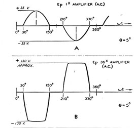
When θ exceeds 2.5° the signal amplitude at the
Figure 10-7 -Servo-amplifier waveforms at 5°. A, Waveform of signal at grid of V-310; B, waveform at grid of
V-303.
cathode of the pentode, V-308, can increase to the
maximum of 55 volts. The grid, however, is constrained to positive swings of 4.4 volts and negative swings of 2.4 volts. There is consequently
established a voltage difference between grid and
cathode during those portions of the wave when
signal amplitude exceeds ±3.4 volts. During
this part of the wave, that portion of the signal in
excess of ±4.5 volts is amplified at the full gain
of the pentode and appears at the grid of the triode,
V-310, with a gain of 30. When θ equals 5°, the
36-speed signal becomes zero and the only signal
at the output-tube grid is that produced by the
amplified 1-speed order. The relative polarity of
the control transformers must be such that the
amplifier delivers to the grid of the output tube, a
signal of the same polarity as that obtained at the
same point from the 36-speed control transformer
for values of θ between zero and 5°. These conditions must exist if the 1-speed signal is to drive
the motor in a direction to reduce θ to zero.
The waveform of the signal at the grid of the
triode, V-310, when θ equals 5°, is indicated in
figure 10-7, A. The peak-to-peak amplitude is
approximately 70 volts, but the signal is zero for
definite portions of the wave, namely, those portion s during which the 1-speed signal is less than
±3.4 volts. This level, as delivered to the triode
grid is obviously excessive and the amplifier limits,
delivering to the grid of the power tube a waveform as shown in figure 10-7, B. The load in the
cathode of the power tube is a parallel-tuned circuit and the waveform of the grid signal produces
an entirely satisfactory voltage across the servomotor, the harmonic content of the grid signal
having negligible effect on the performance of the
motor.
It should be clear that for values of θ between
2.5° and 5°, when the 1-speed signal is beginning
to appear at the 36-speed amplifier grid, this signal
merely aids whatever 36-speed signal is present in
the cathode, because both signals must tend to
drive the motor in the same direction for values of
θ between zero and 5°, as previously explained.
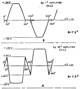
When θ increases to 7.5°, a more complex waveform
results in the output of the triode. In this condition, maximum 36-speed signal of opposite polarity is present in the cathode circuit of the triode
and proper action of the servo depends on the
fact that the amplitude of the 1-speed signal is
204
Figure 10-8 -Servo-amplifier waveforms at 7.5°. A, Waveform of signal from the 1-speed amplifier; B, waveform of
signal from the 36-speed amplifier.
120 volts, whereas the amplitude of the 36-speed
signal is approximately 40 volts (three-fourths
maximum rotor voltage). The 1-speed signal is
zero for appreciable portions of a cycle, however,
and the 36-speed amplifier triode during this time
must receive a net signal of proper polarity for
rotation of the motor to reduce θ to zero. When θ
equals 7.5°, the signal from the 1-speed amplifier
is zero for an electrical angle of from zero to approximately 20° and increases rapidly to a limiting
value of approximately 130 volts because the net
grid-to-cathode signal reaches a maximum of 15
volts causing the pentode to limit. The waveform of this signal is shown in figure 10-8, A.
For the first 20° of a cycle, the cathode of the
triode, V-310, goes positive, and because the grid
signal is zero, the plate potential increases. At
20° the grid begins to go positive as the 1-speed
signal becomes amplified and the a-c component of
the anode voltage rapidly reduces to zero, goes
negative, and limits. Toward the end of the half
cycle, as the 1-speed signal diminishes, the plate
again goes positive, reaching the maximum at an
electrical angle of 160°. This process inverted
repeats in the next half cycle.
The waveform of the a-c voltage at the anode of
the 36-speed amplifier is shown in figure 10-8, B.
239276°-53-14
So far as the motor is concerned, this peculiar
waveform is of no consequence because of the tuned
circuit and the filtering action of the motor itself.
It is necessary only that the voltage wave for a
half cycle have correct polarity for the desired direct ion of motor rotation. For most suitable
action of the servo system, however, it is desirable
that the voltage at the motor does not dip too low
when going through the 7.5° position of θ. For
this reason a definite relationship must be maintained between the amplification of the 1-speed
signal and the proportion of the 36-speed signal
employed.
As θ continues to increase, the "notch" in the
output signal diminishes, and vanishes when the
value of θ is between 10° and 15° because in this
interval the results of the two control-transformer
signals have the same polarity. At 17.5° the
"notch" is again at maximum, but the magnitude
is reduced as compared with that existing when 0
equals 7.5° because the magnitude of the 1-speed
signal has more than doubled and the electrical
angle during which the 1-speed signal is zero, has
diminished. As θ is further increased, the "notch"
finally becomes nearly imperceptible.
For small values of θ less than 2.5°, one factor
which controls the accuracy of the positioning, as
well as the rapidity with which the servomotor
restores the system to balance, is called the
"stiffness" of the system. The degree of stiffness
is determined essentially by the gain of the 36-speed order to the variable phase of the servomotor. Greater stiffness results in more sensitive
and more rapid positioning for small values of θ
but it increases the tendency of the system to
oscillate if the damping factor is not adequate for
a given system stiffness and moment of inertia.
The stiffness of this system and the inherent
damping of the induction cup motor are such that
no additional electrical damping is required.
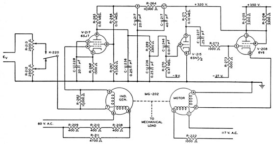
Rate Servo System
The rateservo, or integrator, is an electromechanical system designed to rotate at a speed proportional to an adjustable signal. This servo is
one of the most important devices employed in
the OKA-1 equipments. In its most exacting
application, the rate servo controls the speed of
the range recorder stylus mechanism. It is a
requirement of this range recorder that the stylus
speeds be at either of two basic rates which are
205
Figure 10-9 -Rate-servo schematic.
in the ratio of 2.5 to 1, and that both basic rates
be adjustable over a range equivalent to a sound
velocity of from 4,600 to 5,100 feet per second.
The mechanism must operate at sufficient power
level so that the variation in load during the excursion of the stylus does not cause error in speed,
and that power is available for the operation of
the recorder chart drive. The complete circuit is
shown in figure 10-9.
The mechanical portion of the system consists
of a motor generator, MG-202, driving the mechanical load through suitable gearing. The
motor variable phase is driven by an amplifier
which will be described in detail, the input signal
being the difference between an arbitrary adjustable signal and the output of the induction generator. Polarity of the induction cup generator
signal is such that it attempts to reverse the voltage applied to the motor, but complete cancellation is not possible because the generator output
must approach zero as the motor speed approaches
zero, and the fixed signal amplified at the full
gain of the amplifier is available to drive the
motor. In all cases the fixed signal exceeds the
generator voltage and if the motor attempts to
slow down for any reason whatever, more net
signal is applied to the power-tube grid, because
the signal difference increases and the motor tends
to speed up.
Correspondingly, if the motor speed is excessive, the amplifier signal is diminished, the motor
voltage decreases, and the motor slows down.
This method of speed control is analogous to a
conventional feedback amplifier and the feedback
ratio is the ratio of the generator voltage to the
net signal at the input amplifier under normal
operation. If this feedback is large enough, it is
evident that the motor must run at a speed demanded by the fixed signal, regardless of variation in power supply voltage, mechanical load, or
system frequency.
Either of two fixed signals is selected by a transfer contact of a relay, K-220. One signal may be
adjusted from zero to one-half the available voltage, Ev and the other from one-half to the full
voltage of Ev, by two potentiometers-R-212 and
R-213. In calibration, the larger signal is first
set so that the recorder operates at the proper
speed on the 1,500-yard scale excursion rate, and
the other adjustment is then set for correct operation at the 3,750-yard rate, the result being that
the signals have a ratio of precisely 2 ½ to 1. The
voltage, Ev, is externally adjustable to be proportional to the velocity of sound between the
limits of 4,600 and 5,100 feet per second. Therefore, the "asking" signal is proportional to the
velocity of sound, and the motor speeds are
206
proportional to the velocity of sound at the two
basic rates required.
It is essential that the asking signal and the
generator induced voltage be of identical time
phase in order to avoid an excessive out-of-phase
component of signal which would overload the
amplifier and produce no torque in the motor.
The generator is excited from the 60-volt winding
of a transformer through a series resistance
consisting of R-211 in parallel with the series
combination of R-208, R-209, and R-210, all
three of which are resistors with a negative
temperature coefficient. The magnitude of these
resistances and the temperature coefficient of the
temperature-sensitive resistors are such that
the magnitude and phase angle of the generator
output voltage are independent of temperature.
The difference signal is amplified in a pentode,
V-217, the gain of which is reduced by omission
of the bypass capacitor in the screen circuit.
The output of this pentode is delivered to a
phase-shifting frequency selective network which
eventually furnishes the signal to the biased grid
of a triode, V-215. This network performs two
important functions. First, it serves to prevent
regeneration of high frequencies through the
system and more specifically, to prevent regeneration of harmonics of the 60-cycle system voltage.
Secondly, this capacitor causes a large lagging
phase shift in the signal across it. This angle of
lag is further increased by R-269 and the other
section of C-236. The phase angle change is
excessive because of the amount of harmonic
regeneration suppression required. Because of
this change, approximately 20° of leading phase
shift is provided in the coupling to the triode
amplifiers V-215. The output of the triode is
coupled to the power-tube grid which is biased at
-27 volts.
The lagging phase shift of the amplifier output
necessitated by the harmonic suppression in the
output of the pentode amplifier accomplishes
quadrature relation of the motor voltages. The
fixed phase is connected to the line through a
series resistor, R-222, to aid in obtaining the
required phase shift.
Relation of the OKA-1 to Sonar Systems
With the background of the OKA-1 equipment
computations and the fundamental theory involved
in its operation set forth previously, it is possible
to appreciate the exact relationship of the OKA-1
equipment to the azimuth echo-ranging and
depth-determining equipments. The complexities
of the synchro systems involved and of the
interrelationships between OKA-1 and the depth-determining equipment make very desirable a
simplified block diagram of that portion of the
complete sonar installation with which the OKA-1
equipment is directly concerned.
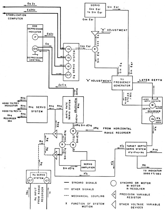
Such a diagram is shown in figure 10-10. The
meaning of the various symbols used is explained
in the legend accompanying the diagram. This
diagram does not show any details of primary
equipments other than those involved directly in
the calculating requirements of OKA-1.
Only two sources of primary information need
be considered in describing the circuit relationships
depicted-sonar depression, Eq, and sonar range,
Rq. The quantity, Eq, originates in the Eq
mechanical system, which is controlled by a 1DG
differential generator in the depth-determining
equipment depression control. Regardless of the
input synchro order to this generator, the operator
is required to position the 1DG rotor by means of
mechanical correction, jEq, so that on-target
indications of the DDI cathode-ray tube are
obtained. This synchro order is accepted by a
1CT and associated servo amplifier in the OKA-1
equipment, supplying the angle Eq as a mechanical
position, and positioning three 1G synchro transmitters. One of these 1G synchros transmits Eq
as a 2-speed order, to a 1F synchro motor in the
depth-determining equipment to indicate Eq to the
depression-control operator. The other two 1G
synchros, geared at 2-speed and 36-speed transmit
Eq to the stabilization computer.
Sonar range, Rq, is made available at 10,000
yards per revolution at 1-speed and 36-speed.
These synchro orders are accepted by the Rq servo
amplifier, making Rq mechanically available in the
calculating circuits. This mechanical system has
the primary task of driving two voltage-variable
devices, having an output proportional to sonar
range.
The Eq mechanical system drives a resolver
which provides two voltages-one proportional to
sin Eq and the other proportional to cos Eq. The
latter voltage is further altered by the ratio of
sound velocity below the thermocline to sound
velocity in the isothermal layer. The device
effecting this alteration is the circuit associated
with the B adjustment dial of the range computer
unit. The B dial is set to ΔV obtained from BT
readings and computed according to fleet doctrine.
In the circuit associated with the B adjustment
the equation (10-1) is solved to provide the sin Eqr
output. This altered signal is supplied to an
amplifier driving a servo system to provide the
sine of an angle defined as the refracted depression
angle, Eqr.
Cos Eqr is converted into sin Eqr by means of a
servo system, because the sine of Eqr is required by
the Vz frequency generator. The two signals,
sin Eq and sin Eqr, form the basic speed controls
for a rate servo and power amplifier combination
delivering a variable frequency to the recorder
stylus motor of the depth-determining equipment.
It has been established previously that Vz, the
vertical component of the velocity of sound, is
defined as V sin Eq before refraction and (V-ΔV)
sin Eqr after refraction. The maximum velocity
difference provided in the refraction adjustments
is 200 feet per second, and because V is of the order
of 5,000 feet per second, (V-ΔV) cannot differ
from V by more than 4 percent. The calculation
of Eqr cannot be considered valid to an accuracy
of greater than 4 percent and therefore it is
assumed that the sound velocity itself, before and
after refraction, is the same, and in actual magnitude may be some average value.
This average value of V is designated Va and is
set on the A adjustment dial in the Vz frequency
generator. The output frequency at the Vz frequency generator is proportional to Vz and equals
Va sin Eq and Va sin Eqr before and after refraction, respectively. The layer depth contacts of
the depth recorder govern selection of the depth at
which Eqr is substituted for Eq. The entire combination is shown for simplicity in the diagram as
the Vz frequency generator. The Vz frequency
generator supplies its output to the stylus motor
of the depth recorder, the stylus of which is to be
driven at a speed proportional to the Vz frequency
generator output. The stylus then provides target depth, Hq, indication.
An equipment function not depicted on the
diagram is the keying and clutch control of the
depth-determining equipment with the related
function of synchronization of keying of both
sonar equipments. It is essential that these equipments be synchronized in order that transmission
pulses of one equipment do not blank out incoming
echoes on the other equipment. Synchronization
is accomplished simply by supplying synchronized
keying pulses to the sonar equipments.
An inspection of the recorder chart and the
positioning of a suitable index to the average indications of the chart enables an observer to determine target depth. Target depth could be considered a third item of primary importance injected
into the calculating circuits, but target depth is a
calculation modified by observer opinion in respect
to the exact setting of the index, and hence is not
primary externally derived information.
A 1G transmitter geared to the depth recorder
index makes available an order of relative target-depth- H'q at 2,000 feet per revolution. This
target-depth calculation is accepted in the calculating circuits by a 1CT and associated servo amplifier, making depth available as a mechanical
function. A 5G transmitter displaced with respect to the 1CT by an angle equivalent to the
projector depth below the surface, Pvq, makes true
target depth, Hq, available for remote indication.
A voltage variable device driven by this system
provides a voltage proportional to target relative
depth, H'q. For simplicity, these circuits are
shown as a single block marked "target-depth
servo system" in the diagram.
The voltage H'q is combined with Rq from the
range servo system to produce sin cEtq-
H'q / Rq = sin cEtq. (10-3)
This signal then drives two resolvers, one of which
gives outputs equal to cos cEtq and sin cEtq. In
the other, range rate, dRq, is multiplied by sin
cEtq, producing dRq sin cEtq. This value in turn
is combined with horizontal range, Rhq-the derivation of which will be explained later-in a comparison servo system to produce ΔcEq which is
supplied to the depth-determining equipment as
the aiding tracking signal.
Horizontal range is computed by taking the cos
cEtq output previously mentioned and combining
it in a voltage-variable device in accordance with
the equation-
Rq cos cEtq=Rhq. (10-4)
209
This output is then fed (1) to the horizontal range
indicators which utilize 1-speed and 36-speed to
position its stylus, and (2) to the ΔcEtq computing
circuits explained in the previous paragraph.
The ΔcEq rate servo system performs the function of transmitting the incremental computed
depression angle, ΔcEtq, to the depression control
in the depth-determining equipment. The advantage of providing the rate of change of cEtq
rather than cEtq directly as aided tracking is that
cEtq may be changed abruptly and cause loss of
contact with the target. When for any reason
the depth recorder operator moves the cursor to
a different position, the H'q order changes and
therefore angle cEtq suddenly has a different value.
If the order cEtq were supplied directly to the depression control, the system would tend to move
off the target and it would be difficult to regain
contact. When the rate of change of cEtq, is
supplied to the depression control, however, Eq
is not immediately affected by changes in H'q,
but the rate at which cEtq changes provides the
aided tracking to facilitate maintenance of contact.
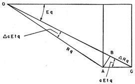
The relationship which the ΔcEq rate servo
system must satisfy may be demonstrated best by
reference to the simplified diagram in figure 10-11,
in which point O represents the ship's transducer,
and points A and C two respective positions of the
target. As the target moves from point A to
point C, the change in slant range, ΔRq, is equal
to the distance BC and the change in depression
angle, ΔcEtq, is equal to angle AOB. Because
small angles expressed in radians are equal to their
sines,
Angle ACB is essentially equal to cEtq, and distance OA is equal to Rq. Therefore, omitting
second-order differences, equation (10-5) may be
restated as follows:
ΔcEtq = -(ΔRq tan cEtq) / Rq
= (ΔRq sin cEtq) / (Rq cos cEtq)
= (ΔRq sin cEtq) / Rhq.
If dRq is substituted for ΔRq and direction is
neglected,
dcEtq = (dRq sin cEtq) / Rhq. (10-6)
The manner in which the ΔcEtq rate servo system
accomplishes the function expressed in equation
(10-6) is described as follows.
The second voltage variable device in the cEtq
servo system is excited by a voltage proportional
to range rate dRq and produces as its output a
voltage which is proportional to the range rate,
dRq, times sin cEtq. The voltage constitutes the
input signal to the ΔcEq rate servo system. The
rate servo previously described in this chapter was
provided with fixed excitation to the induction
generator. The ΔcEq rate servo, however, is
provided with excitation which is proportional to
horizontal range, Rhq. This excitation voltage is
derived from a power amplifier the input signal of
which is voltage Rhq, previously described as being
the output of a voltage variable device in the Rq
servo system.
The output of the induction generator is dependent upon its speed, and upon the magnitude of its
excitation voltage. If the input signal to the rate
servo is constant, the speed of the motor generator
must be equal to some constant times the input
signal in order to provide a generator output
voltage which is equal to the input signal. Actually, the output voltage must be slightly less than
the input signal to furnish a difference signal which
is amplified to drive the motor. The magnitude of
this difference signal is dependent upon the gain
of the amplifier, and in this system the gain is
sufficient to make the difference signal required
small enough relative to the input signal to be
disregarded in the required calculations. The
generator output voltage, therefore, equals the
rate servo input signal.
210
Figure 10-12. -OKA-1 function in the sonar system.
211
The induction generator output may be expressed as an equation-
E= K X S X Rhq, (10-7)
where E is the generator output voltage, K is a
constant, S is the speed of the motor generator,
and Rhq is the excitation voltage.
But the generator output voltage equals the input signal to the rate servo system, and therefore,
K X S X Rhq = dRq sin cEtq
or,
K X S = (dRq sin cEtq) / Rhq
From equation (10-6)-
K X S = dcEtq. (10-8)
Thus the speed of the ΔcEq rate servo motor is
proportional to the rate of change of cEtq. A
1G synchro transmitter is geared to the motor,
making the incremental apparent depression angle,
ΔcEq, available as a synchro order.
A control circuit is provided in the OKA-1
equipment whereby the full scale value of the
depth-recorder chart can be changed from 1,500
to 150 feet. This change is effected by causing
the Vz rate servo to operate at a speed proportional
to 10 sin Eq instead of sin Eq, when excitation is
applied to the expanded scale relay in the range
computer. It is imperative that Eq be at least
2° when operating with the expanded scale on,
because a limit switch in the Eq system stops the
Vz generator when Eq is 2° or less.
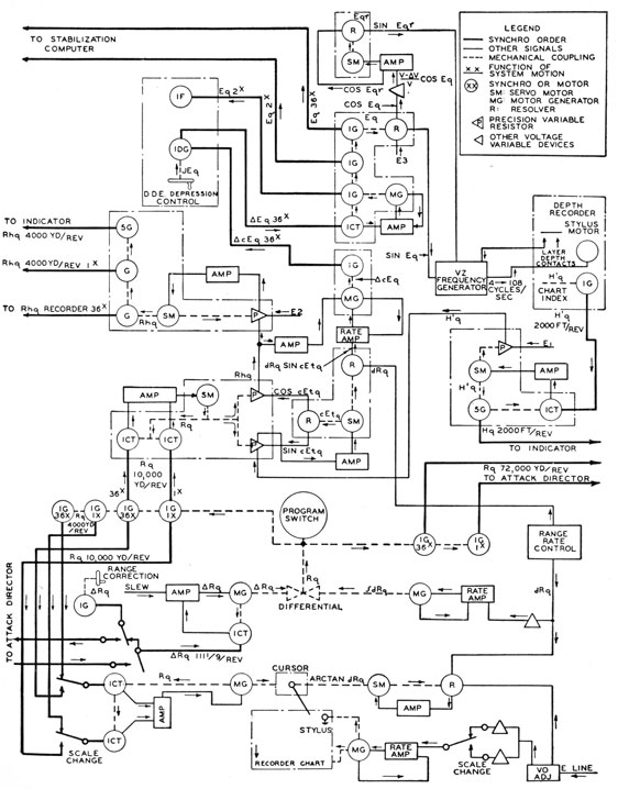
For reference, figure 10-12 shows a complete
functional diagram of the OKA-1, including the
range recorder.