Typical Drawings That Outside Machinists Must Re Able To Read
Since all outside machinists are required to read blueprints which
give locations of holes, sizes of holes, and locations of certain units
to be installed, and since this manual is not intended for comprehensive
instruction in blueprint reading, the following specimen prints are
inserted so that the outside machinist trainee may develop an appreciation
of the types of blueprints which he must learn to read as a part of his
daily work.
Following the prints are questions pertaining to each print. The
questions are typical of information which the outside machinist must be
able to obtain readily from blueprints. All the questions may be answered
from the prints shown here. Most answers may be found from the specific
print under which the question is listed.
256
257
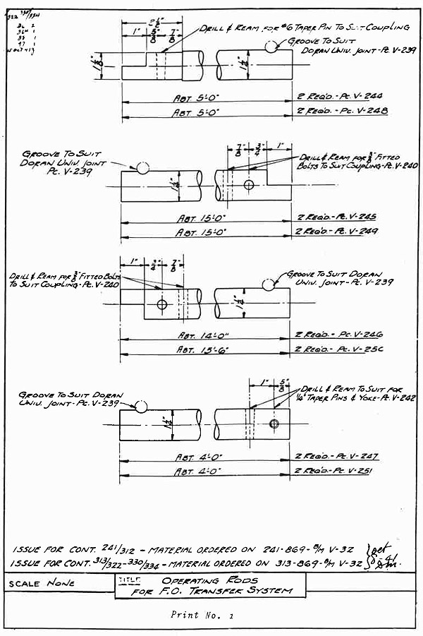
PRINT NO. I INSTRUCTIONS
The. title of blueprint No. 1, Operating Rods, automatically indicates that the shape of the rod stock is round and not square. For this
reason there is no necessity for showing an end view of the rod, on this
or on a similar blueprint.
The lengths of the. rods are given as though the blueprint were full
length. To avoid confusion, the rod is "broken' at a point between
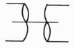
the ends. The "break" is indicated by the symbol shown below:
This sort of symbol always means a rod or shaft
has been cut and it also shows the round shape
of the rod. Such a "break" does not mean that
the rod has actually been cut. The use of the
symbol indicates the rod between the broken
ends is plain, no holes or other cuts, and full
size all the way.
"Drill and Ream for 3/8" fitted bolts to suit Coupling Pc V-240"
means that V-240, the piece number of the coupling, has been
drilled and that the rod must be drilled and reamed to suit the
coupling. When reaming for a #6 tapered pin use a #6 tapered
reamer. The size drill to use is found from the diameter of the
small end of the tapered pin.
"Abt. 15'-0"" means that the rod is about 15'-0" long from end to
end or "over all" as it is usually expressed.
"Groove to suit Doran Universal print Pc V-239" means that a groove
must be filed or milled in the rod to suit the vole that is drilled
in the piece V-239.
The step in the end of any one of the rods shown is milled or hack-sawed and filed to the dimensions given. The ends of the rods
should be square with the outside diameter before the measurements
are taken.
The letters "F. 0." in the title mean Fuel Oil. The notation "Scale,
none" means that the drawing or blueprint is not made to scale.
Work to the dimensions. Never measure a blueprint.
258
This Page Blank.
259
PRINT NO. 1
QUESTIONS AND PROBLEMS
1. What is the diameter of the operating rod stock that is
used to make the parts shown?
2. How many "stepped" rod ends are shown?
3. What size reamer is used to ream the taper holes in the
rod ends?
4. How many different length operating rods are shown on this
blueprint?
5. What does the abbreviation "Univ." mean?
6. Where should one get the information that will decide what
size drill is to be used for drilling before reaming the
tapered holes?
7. Why is the stepped end of the rod in the top figure on the
blueprint reduced to 1-1/8" diameter?
8. Should the grooves in the ends of the rods be filed or
drilled?
9. Explain the difference between a universal joint and a
coupling.
10. How far is the face of the step from the outside diameter
of the rod in the top figure?
260
261
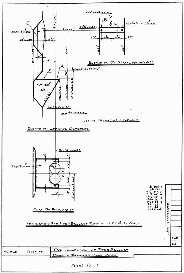
PRINT NO. 2
INSTRUCTIONS
Blueprint No. 2 shows how the several members of a pump foundation
are welded to the bulkhead of a ship. It is the job of the outside
machinist to lay off' and drill the holes shown.
Note the center line of the pump which extends from and through
the Plan of Foundation view to and through the Elevation Looking Outboard view. The letters "" at the upper end of the center line mean
"Center Line" on any blueprint. When beginning to lay out the work
for any job, always find or locate a center line from the blueprint
and then take all other measurements from the center line.
Sometimes the dimensions seem to be missing. Usually the dimensions may be found by adding or subtracting certain dimensions which
will be given adjacent to the location of the missing dimension.
For example: Line "" is 6" from the face of the corrugation in
the bulkhead. The face of the corrugation in the bulkhead is 15" from
the pump "". Therefore the edge represented by line "C" is 21" from
the pump "". Other similar dimensions may be found the same way.
"DBE" means "double".
"Cont." means "Continuous."
"FLG" means "flange".
"ab" means "identification of plate" or "piece mark of plate".
"PLT" means "plate".
"RHO" means "bulkhead".
The symbol for "angle" is .
"aa" means "identification of plate" or "piece mark of plate".
"13.5#" means "thirteen and one-half pounds".
NOTE: The "13.5#" refers to a plate which is just
thick enough to weigh 13.5 pounds per square
foot of area. A piece of this plate ten feet
square weighs 1350 pounds.
The notation "Port Side Only" means that the foundation is to be
installed on the port side of the ship but that there is no foundation
to be installed on the starboard side.
262
This Page Blank.
263
PRINT NO. 2
QUESTIONS AND PROBLEMS
1. The view at the upper left is marked: "ELEVATION LOOKING OUTBOARD." Examine the blueprint closely and state
whether the outboard direction is port or starboard.
2. Looking at the plan of foundation view, state how far the
centers of the two large circles are from the forward
face of MID. No. 73.
3. What are the diameters of the two large circles in the
foundation plan?
4. Are both circles the same diameter?
5. State the center to center distance of the two large
circles in the plan of Foundation view.
6. In the elevation Looking Outboard view, how far is the
edge marked "A" from the center line of the pump suction?
7. In view, Elevation of Stay, looking aft, how far is edge
"B" above center line of stay?
8. What is the center-to-center distance of two 7/8" holes
in the elevation of stay view?
9. What weight plate "pc mark aa", is specified for the top
of the shelf for the foundation?
10. What is the distance from the top of shelf "E" to the
center of the stay shown in the Elevation of Stay Looking
Aft?
264
265
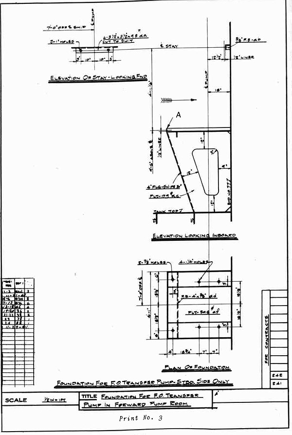
PRINT NO. 3
INSTRUCTIONS
Blueprint No. 3 shows the foundation for a fuel oil transfer pump
on the starboard side of the ship. The foundation is welded to the
after face of bulkhead No. 77 and rests on the tank top. Longitudinals,
numbers 75 and 76 are partly shown in the Elevation Looking Inboard.
The outside machinist lays out the locations for the bolt holes
and drills them. Center lines are first located and the centers of
the holes are established and center punch marked. The sizes of the
holes shown on the blueprint appear to be the same. A close inspections of the figures will show that there are three sizes of holes
to be drilled.
Notice that when a group of holes is to be drilled the same size
that only one hole is marked but the total number of holes of that size
is -indicated at the same place the hole size is given. For example:
4 - 1 1/4" holes means that there are 4 holes in the group and each hole
is to be drilled 1 1/4" diameter and the holes are drilled all the way
through unless there is a definite dimension given for the depth of
the hole.
In addition to abbreviations which were given on previous information sheets, the following are shown on this blueprint.
"B" means "base line".
"af" means "identification of plate" or "piece mark of plate".
The notation "1/2" liner" means that dimensions are given to or from
the face of a 1/2" thick piece of steel that is to be installed at the
given location some time later. Allowance must always be made for such
liners or other indicated plates.
"ad" means "identification of plate" or "piece mark of plate".
266
This Page Blank.
267
PRINT NO. 3
QUESTIONS AND PROBLEMS
1. Is the arrow, near the top of Elevation Looking Inboard,
pointing forward or aft?
2. State the number of 7/8" holes in the foundation.
3. How many 1-1/4" holes are there in the foundation?
4. What is the distance, center to center, of the 1" holes
in the stay?
5. On which side of the ship is the foundation located?
6. State the distance from edge "A" to pump center line.
7. What shape of stock is F. B.-4' x 3/8" add?
S. State the center of hole to center of foundation distance
of the 7/8" holes in the plan foundation.
9. How far is the center line of these holes from the pump
center line?
10. State the distance from the top of the 1/2" lines, inboard
elevation to the base line of the ship.
268
269
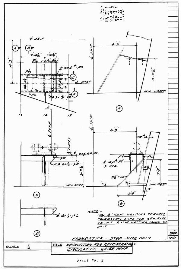
PRINT NO. 4
INSTRUCTIONS
Blueprint No. 4 shows a foundation for a circulating water pump.
The blueprint shows the side view, the end view, and the top view of
the pump in phantom outline.
The key letters in the small circles are for the guidance of the
shipfitter when he is installing the foundation plates and supports.
The outside machinist lays out the hole locations and drills them.
Measurements are taken from the ship center line as on other jobs.
The pump unit is placed, leveled, and chocked. The hole locations are
then found through the holes in the base of the pump unit and worked on
the foundation top as they are drilled through the base.
Some additional abbreviations and symbols are used on this blueprint.
"pa" means "identification of plate" or "piece mark of plate".
"pd" means "identification of plate" or "piece mark of plate".
"Inn. Bott." means "inner bottom".
"pb" means "identification of plate" or "piece mark of plate".
"pt" means "identification of plate" or "piece mark of plate".
"pc" means "identification of plate" or "piece mark of plate".
"F.B." means "flat bar".
"Eng. Rm. Fl." means "engine room floor".
The figures"13,", "14", "15", in the upper left corner view are
frame numbers.
PRINT NO. 4
QUESTIONS AND PROBLEMS
1. How many holes are shown through the base of the unit
that has to be installed on the foundation?
2. State the distance from the center line of the ship to
the center line of the pump base.
3. What is the distance from the inner bottom plate to the
top of the pump foundation?
4. What is the chock or liner thickness under the pump base?
5. What, size are the holes in the pump base?
6. Does the blueprint call for fitted bolts in the base and
foundation?
7. What is the frame number opposite a point about midway
between the Pump motor and the pump?
8. Give the center to center distance, both ways, of the bolt
holes in the foundation.
270
271
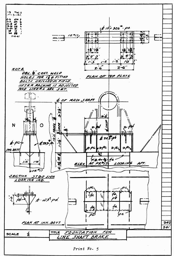
PRINT NO. 5
INSTRUCTIONS
Blueprint No. 5 shows the foundation for the line shaft brake. All
dimensions are taken from center lines as before.
Study this blueprint carefully. The job is very simple to do. The
line shaft brace unit is set on location according to the blueprint
measurements given. Chocks have to he fitted and holes drilled for the
bolts which hold the unit to the foundation.
There are a few abbreviations and symbols not previously mentioned:
"STDB. SIDE LOOKING INB." means "Starboard Side Looking Inboard.
"fa" means "identification of plate" or "piece mark of plate".
"FB" means "flat bar."
"ph" means "identification of plate" or "piece mark of plate".
PRINT NO. 5
QUESTIONS AND PROBLEMS
1. Does the blueprint call for fitted bolts in the two welded
side brackets?
2. What size bolt holes are drilled and reamed in the brackets
and foundation?
3. On what center line is the foundation set?
4. How far is the center of the brake drum above the base
line of the ship?
5. What thickness chock or liner is used under the base of
the installation?
6. Which side of the section "Starboard Side Looking Inboard"
is forward? N? or O?
7. What is the longest distance, center to center of any two
bolt holes in the foundation?
8. What is the shortest distance, center to center of any two
bolt holes in the foundation?
272
273
PRINT NO. 6
INSTRUCTIONS
Blueprint No. 6 shows a foundation for a drain cooler. The cooler
is supported on two fabricated steel brackets which are welded to frame
No. 31. The outside machinist lays out the hole locations and drills
them.
All measurements are taken from center lines as before. The unit
is placed correctly, chocks are fitted, and the cooler is bolted down
in place.
"Boiler Rm. Flat + 26'-0"" means "above base line".
The reference letters "A" and "A" are intended for the shipfitter
when he is installing the bracket supports for the cooler. The letters
indicate the correct location for the bracket shown in the left-hand
view.
"1'-2" D means "one foot and two inches diameter".
PRINT NO. 6
QUESTIONS AND PROBLEMS
1. What size holes are drilled and reamed for the drain
cooler pedestals?
2. How many bolt holes are there in one pedestal?
3. What is the distance from frame number 31 to the center
line of the drain cooler?
4. What is the thickness of the chock or liner between the
pedestal and the foundation?
5. Give the center-to-center distance of the hole centers
in the pedestal feet, parallel to frame number 31.
6. State the longest center-to-center distance between any
two of the holes in the foundation, measuring parallel
to the center line of the cooler.
7. What is the center distance of the cooler from the boiler
room flat?
8. Which is the forward side of the plan view? R. or S.?
274
275
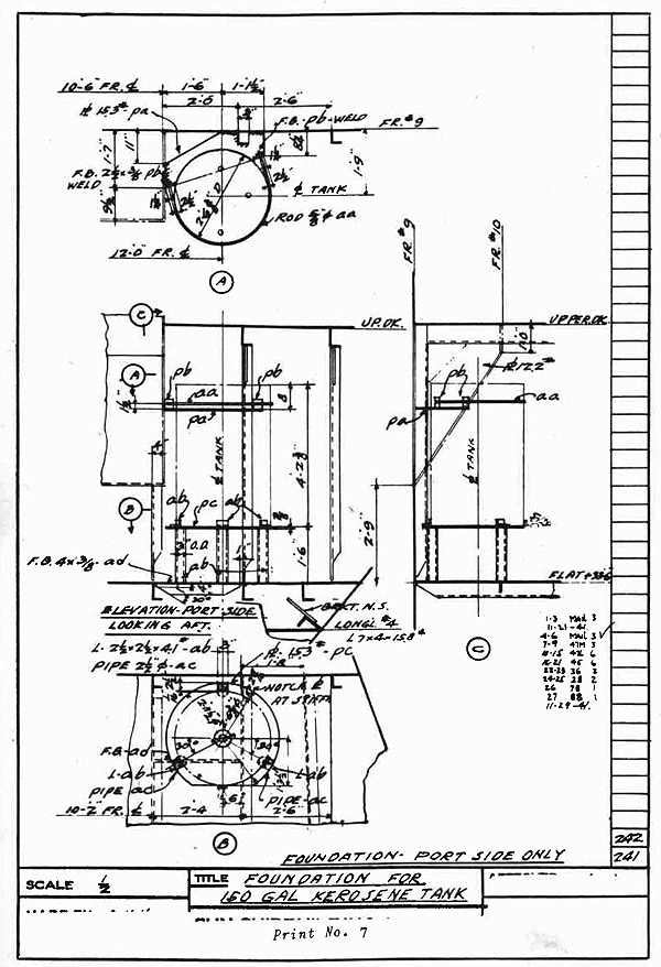
PRINT NO. 7
INSTRUCTIONS
Blueprint No. 7 shows a foundation for a 150-gallon kerosene tank.
The tank is installed to rest on three pieces of 2 1/2" pipe 1'-5 5/8"
long. The pipes are supported by the flat shown in the view at the
right. See section C. Angle clips are placed at suitable intervals
around the bottom of the tank on the supporting plate. to secure the tank
in position.
A rod around the top of the tank, shown in the top view, holds the
top of the tank securely. A plate is welded in the corner formed by
frame #9 and the bracket shown in the right-hand view. The bracket extends from frame #9 to frame #10. See section C.
Angle clips are welded to the plate just mentioned and holes for
the rod around the top of the tank are drilled in the clips. A nut on
either end of the rod clamps the tank tightly in place.
Some abbreviations and symbols not mentioned before are:
"Brkt. N.S." means "bracket on near side".
"longl." means "longitudinal".
"Up Dk." means "upper deck".
"stiffr" means "stiffener".
"L-ab" means "angle identification" or "piece mark of angle bar".
"10'-2" Fr. " means "10'-2" from center line".
"O.D." means "outside diameter"
"L 7 x 4 x 15.8#" means "longitudinal #4 is an angle bar
7" x 4" x 15.8#- means a section taken through this way,
looking the way the arrow points is a symbol for diameter.
PRINT NO. 7
QUESTIONS AND PROBLEMS
1. On Section A what is the diameter of rod holding the
kerosene tank?
2. How far is the of Kerosene tank from the of ship?
3. How far is the kerosene tank from #9?
4. To what diameter must the rod be bent to take the tank?
5. What is the distance from the bottom of tank to the base
line?
6. Which is the forward side of the Plan View?
7. What is the distance from the rod to the top of tank?
8. What is the distance from the flat to the rod?
276
277
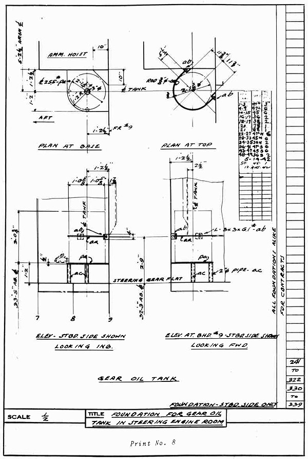
PRINT NO. 8
INSTRUCTIONS
Blueprint No. 8 shows a foundation for a gear oil tank located in
the steering engine room. Notice the wording under each view which is
intended to show the relationship of the views.
The plate under the tank is supported by pipes which are secured
to the steering gear flat.
The tank is held in place by one rod fastened around the middle.
There is a nut on either end of the rod to draw it tight through angle
clips welded to the bulkhead.
Some additional abbreviations and symbols follow.
"32'5" AB.B" means "33'-5" above base line".
" is a symbol for diameter.
"AMM" means "ammunition".
"O"" means "over all".
PRINT NO. 8
QUESTIONS AND PROBLEMS
1. On which side of the ship is the gear oil tank located?
2. How far is the of tank from the of ship?
3. How far above the steering gear flat is the rod located?
4. To what diameter must the rod be bent to take the?
5. What, is the distance from Fr #9 to the
6. What is the distance from base line to bottom of tank?
7. What is the diameter of the rod?
8. On the sketch "Plan at Top" which is the forward side?
278
This Page Blank.
279
APPENDIX II
Shipyard Outside Machinist Terms and Definitions
A
Abaft--Aft of; farther aft than.
Access Holes--Holes cut in the
structure of a ship to permit entering or leaving various compartments.
Accommodation Ladder--A portable
ladder or stairway hung over
the side of a ship to accommodate people who are boarding from, or disembarking to,
small boats or a pier.
Aft--Toward, at, or near the stern.
After--Nearer stern.
Aftermost--Nearest the stern.
After Body--A hull form aft of the
midship section.
After Peak--The compartment in the
narrow part of the stern, aft
of the last watertight bulkhead.
After-Peak Bulkhead--The water tight
bulkhead farthest aft.
After Perpendicular--A vertical
straight line at, or near, the
edge of the rudderpost.
Air hammer--A hammer driven by compressed air for riveting;
sometimes called an air gun
or "gun".
Air Port--A circular opening or
window through the side of the
ship, or deck house, to admit
light and air.
Amidships---At or near the middle of
the ship between stem and
stern.
Anchor--A heavy, hook-shaped device
for holding a ship at rest in
water. The anchor grips the
ocean bottom and is fastened
to the ship by a chain.
Angle Clip--A short piece of angle
bar.
Angle Collar--A ring made of angle
bar.
Anneal--To soften metal by heating
and allowing it to cool slowly.
Aperture--The recess in which the
propeller is located.
Apron Plate--A small plate at the
prow of the ship to stiffen
the top of the bulwark.
Assemble--To fit together the small
parts of a larger member or
unit and make so it complete.
Athwartship--Across the ship at
right angles to the centerline.
Auxiliaries--Machinery supplementary to main propulsive units.
Awning Deck--A shade deck above
another deck.
B
Ballast--Any weight or weights
(usually sea water) used to
keep the ship from becoming
"top heavy" or to change her
trim.
Ballast Tank--Watertight compartment to hold ballast.
Barnacles--Small marine growths
that attach themselves in large
numbers to the hull of a ship.,
often greatly retarding its
speed.
Battens--Long strips of wood used
in the mold loft for fairing
lines; also, wooden protective
strips in cargo holds; see
hatch battens.
280
Beams--An athwartship member supporting a portion of a deck;
also, the width of the ship.
Beam Knee--(See Brackets.)
Below--Below a deck or decks (corresponding to "down stairs").
Bending Rolls--The rolls of a large
machine used to give curvature
to plates.
Bending Slab--A large floor made
up of heavy, perforated,
cast-iron slabs arranged in a
manner which permits bending
frames, angles, etc.
Berth--The place where a ship lies
at anchor or at a wharf; a
place to sleep; a bunk; also,
a specified small section
of the hull structure.
Between Decks--The space between
any two decks.
Bevel--The angle between the
flanges of a frame or other
member (When greater than a
right angle, open bevel; when
less, closed. Also, to chamfer.
Bilge--The curved section between
the bottom and the side of a
ship; the recess into which
all water drains.
Bilge Blocks--Supporting blocks
used under the bilge for support during construction or
dry-docking.
Bilge Keel--A fore-and-aft member
fitted to the outside of the
shell plating along the bilge
to prevent excessive rolling
of the ship.
Bilge Pump--A pump for removing
bilge water.
Bilge Strake--The course of plates
at the bilge.
Bilge Water--Water (due to leaks,
sweat, etc.) that collects in
the bottom of the hull.
Bilge Well--A sump to which bilge
water drains.
Binnacle--A case, box, or stand
containing a ship's compass,
adjusting magnets, and a lamp
for use at night.
Bitt--A vertical post to which
mooring lines are made fast;
a bollard.
Bitumastic--An elastic cement used
as a paint to protect steel
Boat Deck--A deck on which life-boats are kept.
Body Plan--A drawing which shows'
frame lines in elevation.
Boiler--A container in which water
is heated to form steam.
Boiler Chocks--Stay braces which
prevent fore-and-aft movement
of boilers.
Boiler Foundation--A support for a
boiler.
Bollard--A single tie post (See
bitt).
Booby Hatch--A watertight covering over a deck opening which
is used for a stairway or
ladder.
Boom--A long, round, heavy spar,
piveted at one end, usually
used for handling cargo, etc.
Boom Rest--A support for a boom when
it is not in use.
Boom Step--A socket for the end of
the boom.
Bosom Piece--A short piece of angle
riveted over a butt joint o
two angles, a butt strap for
angle bars; a splice piece.
Boss--The curved, swelling portion
of the ship's hull around the
propeller shaft.
Boss Frame--A hull frame which is
shaped to clear the propeller
shaft tube.,
Boss Plate--A shell plate covering
the curved portion of the hull
where the propeller shaft
passes outboard.
Bow--The forward end of a ship.
281
Bracket--A triangular plate used to
connect rigidly two or more
parts, such as a deck beam
and a frame, a frame and a
margin plate, etc.
Braze--To heat and join by means of
hard solder (spelter). This
solder may be brass, bronze,
or other alloys.
Breakwater--A braced guard plate
which prevents solid water
from sweeping the decks.
Breast Hook--A triangular-shaped
plate extending horizontally
across the bow behind the
stem, stiffening the stringers
and stem.
Bridge, Navigating --The deck from
which a ship is navigated.
Bridge Deck--The deck on the superstructure amidships, the top
deck of the deckhouse.
Brow--A watershed over an air port;
a small, inclined runway to
allow passage of trucks over
a hatch coaming, or through a
bulkhead door, etc.; sometimes
portable.
Building Slip--The place where a
ship is built; a shipway.
Bulb Angle--An angle shape which
is reinforced at one toe.
Bulb Plate--A narrow plate reinforced on one edge.
Bulb Tee--A tee bar with toe of
web reinforced.
Bulkhead--A vertical partition
corresponding to the wall of
a room, extending either
athwartships or fore and aft.
A steel partition in a ship.
Bulkhead Sluice--A small opening
in a watertight bulkhead which
can be opened or closed from
the deck above.
Bulwark--The side of a ship above
the weather deck.
Bull Riveting--Driving rivets by
squeezing them with a high-powered
air or hydraulic
machine.
Bunker--A compartment used for the
stowage of coal or other fuel.
Buoyancy--Ability to float; lifting power when immersed.
Butt --The joint formed when two
parts are placed edge to
edge.
Buttock--A distance from center-line determined by the
section of the moulded surface with a vertical longitudinal plane.
Butt Strap--A small plate used to
connect the two parts of a
butt joint by overlapping
each; a splice piece.
C
Camber--The athwartship rise or
crown of a deck.
Cant Frame--A frame which is not
square to the keel line.
Capstan--A revolving drum with a
Vertical axis, used for heaving in lines.
Cargo--The freight carried by a
ship.
Cargo Battens--Strips of wood
used to keep cargo away from
the steel hull.
Cargo Boom--A heavy boom used in
handling cargo.
Cargo Hatch--A large opening in a
deck which permits the loading of cargo into holds.
Cargo Tort--An opening in a ship's
side used in loading and unloading cargo.
Casing--Bulkheads enclosing a portion of a vessel, as the boiler
room casing. Also a covering
for parts of machinery.
Calk--To make a joint watertight.
Calker---One who calks.
Ceiling--Wood sheathing on the tank.
top, sides of a ship, and bulkheads; used to protect cargo.
282
Center Keelson--(See vertical keel).
Center Line--The middle line of the
ship, extending from stem to
stern.
Chafing plate--A bent plate used to
minimize chafing of ropes, as
at hatches.
Chain Locker--A compartment in the
forward portion of ship in
which anchor chain is stowed.
Chain Pipe--A pipe for passage of
anchor chain from deck to chain
locker.
Chain Riveting--Two or more rows of
rivets spaced so that the rivets in one row are opposite
those in an adjacent row.
Chain Stopper--A device which prevents anchor chain from running out. It is moved into
position after the anchor has
been dropped.
Chamfer--To cut off the sharp edge
of a corner. To bevel.
Chart Room--A small room adjacent
to the pilothouse in which
charts and navigating instruments are located.
Chock--A heavy fitting through which
ropes or hawsers are led, saddle or seat of wood or metal.
Chock, Boat--A cradle or support
for a lifeboat.
Chock Roller--A chock with a sheave
to prevent chafing of ropes.
Cleat--A fitting having two arms or
horns around which ropes are
made fast. A clip on the
frames of a ship used to hold
cargo battens in place.
Clinching Pan--A flat plate for
clinching nails (Used in the
mold loft.)
Coaming--The vertical boundary of
a hatch or skylight.
Cofferdam--A narrow vacant space
between two bulkheads , a
double watertight bulkhead.
Collar--A flanged band or ring.
A welded plate used to close
a frame or beam penetration
through plating.
Collision Bulkhead--The watertight
bulkhead nearest the bow of
a ship; forepeak bulkhead.
Companionway--A covered stairway
leading downward from an open
deck; a series of steps leading from the deck to a cabin
or saloon below; also, the
space occupied by these steps.
Compartment--A subdivision of a
space or a room in a ship.
Corrugated--Having a series of
wrinkles or grooves arranged
so as to produce stiffness.
Corrugated Bulkheads--Bulkheads
with corrugated plating which
eliminates the need for many
welded stiffeners.
Counter--The overhang of the stern
of a ship.
Countersink--To taper a hole for
a flush rivet or bolt.
Cowl--The hood-shaped top of a
ventilator pipe.
Cradle--A form on which bows, Etc.,
are assembled; the support in
which a ship rests during
launching, a launching cradle.
D
Davit--A crane arm used in handling small boats, lifeboats,
stores, gear, etc.
Dead Flat--A portion of a ship's
side or bottom where the plating has no curvature; also
the midship portion of constant cross section (the parallel middle body).
Dead Rise--The rise or upward slant
of the bottom of a ship from
the keel to the bilge.
Dead Weight--The total weight of
cargo, fuel, water, stores,
passengers and crew (and their
283
effects) which a ship can
carry.
Deck--The part of a ship corresponding to the floor of a
building.
Deckhouse--A shelter built on deck.
Declivity--The inclination of shipways to provide for launching.
Deep Tank--A deep compartment usually extending from tank top
to lower deck.
Derrick--A device for hoisting
heavy weights, cargo, etc.
Die--A tool for forming a rivet
head (applied to rivet dies) .
Displacement--The total weight of
the ship when afloat, including everything onboard (equals
weight of water displaced).
This total weight is usually
expressed in long tons.
Dog- -A small, bent metal fitting
used in closing doors, hatch
covers, manhole covers, etc-;
a bent bar of round iron used
in holding shapes on bending
slab; any small, flat lug temporarily welded to structure
as backing for a wedge.
Dolly Bar--A heavy bar to hold
against a rivet to give backing when riveting.
Double Bottom--Compartments at the
bottom of a ship between the
inner and outer bottoms, used
for ballast tanks, water, fuel
oil, etc.
Doubling Plate--A plate fitted out
side or inside of another to
give extra strength or stiffness.
Drag --The amount the stern end of
the keel is below the bow end
when the ship is afloat, but
not on an even keel.
Draft--The vertical distance from
the lowest point of the ship
in the water to water level.
Drift pin--A small tapered tool
used in aligning holes in
adjacent members.
Drop Strake--A strake discontinued
near the bow or stern.
E
Erecting--The process of hoisting
into place and bolting the
various parts of a ship's
hull.
Even Keel--A ship is said to be
on an even keel when the keel
is level, that is parallel to
the surface of the water.
Expansion trunk--The raised portion of tank used on some oil
tankers to allow for the expansion of oil when temperature rises.
Eye- -The large hole in the stern
frame which is bored out to
take the stern tube liner.
Eye Bolt--A bolt the head of which
is in the form of a ring or
eye.
F
Fabricate--To make raw material
ready for assembly or erection.
Face Plate--A narrow, stiffening
plate welded along the edge of
any web frame or stiffener.
Fairing or Fairing Up--Correctly
lining up the structural members of a ship assembling the
parts of a ship so that they
will be fair, that is, without kinks, bumps, or waves;
bringing rivet holes into
alignment.
Fair-lead--A fitting through which
or over which a rope, line,
etc., may be led so as to
change its direction without
excessive friction.
Fair water--Plate or casting used to
preserve streamline flow past
hull structure or propeller
hub.
284
Fathom--Six feet.
Fathometer--A device to measure
the depth of water by timing
the travel of a sound wave
from the ship to the ocean
bottom and return.
Faying Surface--The contact surface between two adjoining
parts.
Fender--A portable device made of
wood or rope to protect a ship
when bumping a pier; permanently installed dock extension which protects the hull
of a ship in docking.
Fidley--Casing top over the boiler
room.
Fidley Hatch--A hatch over the
boiler room.
Flagstaff--Flagpole at the stern of
the ship; ensign staff.
Flange--A part of a plate or shape
at, or nearly at, right angles
to the main part; to bend over
to form an angle.
Flare--The sudden widening of the
shell at the top near the bow.
Flat--A small partial deck (built
level) without curvature.
Floor--The lower portion of a transverse frame, usually a vertical plate extending from center
line to bilge, and from inner
to outer arid bottom.
Fore and Aft--In line with the
length of the ship, longitudinally.
Fore-and-Aft Gangway--A walkway between deckhouses at or near
the center line of the ship.
Fore Body--A hull form forward of
the midship section.
Forecastle--The forward, upper
portion of the hull. It is
sometimes used as the crew's
quarters.
Forefoot--The part of the keel
which curves and rises to meet
the stem.
Forepeak--The large compartment or I
tank in the lower part of the
bow of the ship.
Forging--Steel worked to special
shape by hammering while red
hot.
Forward--Near, at, or toward, the
bow of the ship.
Forward Perpendicular--A vertical
line through the intersection
of the stem with the load
water line.
Foundations--Supports for boilers,
engines, and auxiliary machinery.
Foundations, Auxiliary--Supports
for small machinery, such as
winches, condensers, heaters,
etc.
Frames--Ribs forming the skeleton
of a ship.
Frames Continuous--Frames combining side frames and floors.
Frame, Side--Inside frames a ship
connection to the shell plating.
Frame Spacing--The fore-and-aft
distance between adjacent.
frames.
Frame, Web--A heavy side or continuous frame, made with web
plate for extra stiffness.
Freeboard--The vertical distance
from the upper watertight
deck to water line, when the
ship is fully loaded.
Freeboard Mark-- (See Plimsoll
mark).
Freeing Port--A hole through the
bulwark to provide ready
drainage of water from the
deck.
Funnel--A smokestack of a vessel.
Furnace--A heater or large forge
for heating plates or shapes
for bending; to bend by heating in furnace.
285
G
Galley--A cooking room or kitchen.
Galley Dresser--A cook's work
table.
Galvanizing--Coating metal parts
with zinc for protection from
rust.
Gangway--A passageway, a ladder,
or other means of boarding
a ship.
Garboard Strake--The course of
plates next to the keel of
a ship.
Gasket--Packing of canvas composition, or other material,
used in making a tight joint.
Girder--Fore-and-aft stiffening
member for deck or bottom
shell.
Girth--The transverse distance
around the midship section.
Grab Rods--Bent rods welded to
bulkheads or the ship's side
to form a ladder.
Grating--Light platform or walking built up of metal bars,
used for access to machinery.
Grommet--A soft ring used under a
nut or bolthead to maintain
watertightness.
Gross Tonnage--A figure obtained
by dividing the total volume
of the ship, in cubic feet,
by 100 .
Ground. Ways--Timbers secured to the
ground under the hull on each
side of the keel. When the
ship is launched, it slides
down the ground ways into the
water.
Gudgeons--The bosses on the stern
post drillingon which the rudder swings.
Gunwale--The junction of the deck
and the shell at the top of
the sheer strake.
Gunwale Bar--Angle iron which connects stringer plate and shell
plates. (Riveted work.)
Gyrocompass--A mechanical compass
operated by means of a gyroscope. This compass indicates
true north rather than magnetic north.
Gyro Repeater--An apparatus to show
the reading of the gyrocompass
at a distance from the main
gyroscope equipment.
H
Hatch--An opening in a deck for
loading or unloading cargo,
etc.
Hatch Battens--Flat bars which are
wedged against hatch coamings
to secure tarpaulins.
Hatch Beam--A portable beam used
to support wooden hatch covers
Hawse Pipe--Casting, or castings,
through the deck and the side
of the ship at the bow for
passage of anchor chain.
Hawser--A large rope used for towing and mooring.
Heeling--The inclination of a
vessel to one side.
Hogging--Straining of the ship which
tends to make the bow and
stern lower than the middle
portion.
Hold--The inside of a hull; cargo
space.
Hold Beams--Structural members
placed in a hold, similar to
deck beams, but having no
plating or planking on them.
Holder-On--One who "backs up" or
"holds on" the head of a rivet
while the point is being
"driven", or upset.
Horn--To line or square up; also,
part of a cleat.
Hull --The body of a ship, including
shell plating, framing docks,
and bulkheads.
I
I-Beam--A structural shape with a
cross section resembling the
letter
286
Inboard--Inside of the ship; toward
or nearer the center line.
Inboard Profile--A drawing of the
longitudinal section at center
line of ship.
Inner Bottom--Plating forming the
upper surface of the double
bottom. Also called tank top.
Inner Shell--A plated surface or
"shell" inside the outer shell
plating, used as additional
protection in case of collision or other accidents. The
space between the inner and
outer shells is often used as
a storage space for liquid
ballast or cargo.
Inserted Packing--Canvas strips
soaked with red lead and
placed between connections
that cannot be calked successfully otherwise; stop waters.
Intercostal--Made in separate parts
between frames, beams, etc. ;
the opposite of continuous.
(Floors are continuous; longitudinal girders are intercostal inmost cargo vessels.)
Isherwood System--A system of
building ships in which the
main framing is longitudinal
(or fore-and-aft) , instead of
transverse as in ordinary
ships.
J
Jack Staff--A flagstaff at the bow
of a ship.
Joggle--An abrupt bend or offset
in a plate, bar, or frame to
eliminate the use of liners.
K
Keel--The principal fore-and-aft-member of a ship's frame.
The keel runs along the
bottom, connects the stem and
helps to support the frames
of the ship which are attached
to it .
Keel-Blocks--Heavy Blocks which
support the keel of the ship
during construction.
Keel, Flat--The bottom-shell strake
on the center line of the
ship.
Keelson, Side--A fore-and-aft
member similar to the vertical
keel and placed on each side
of it.
Keel, Vertical--Vertical plate
used as reinforcement for the
keel, often called center
keelson.
King Post--A stub mast, outboard
from the center line, used to
carry cargo booms; kingposts
often serve as ventilators.
Knot--A tie in a line; a nautical
mile (about one and one
seventh statute miles.)
Knuckle--A sharp bend in a plate or
shape.
Knuckle Plate--A plate bent to form
a knuckle.
L
Ladder--Inclined steps, used aboard
ship instead of "stairs".
Lap--A joint in which one part
overlaps the other, thus
avoiding the use of a butt
strap; also, the amount of
overlap.
Launching--The operation of placing
a hull in the water by allowing it to slide down on greased
skids called launching ways.
Laying Out--Marking plates or
shapes for shearing, punching,
etc.
Lazarette--A space between decks
used as a storeroom.
Length Between Perpendiculars--The
length of a ship measured from
the forward perpendicular to
the after perpendicular.
287
Length Over All--The length of a
ship measured from the extreme
forward end to the aftermost
point of the stern.
Lift--To make a template from
measurements taken from the
job.
Lightening Hole--A hole cut in a
member to reduce its weight.
Limber Hole--A small hole cut in
a plate near the bottom to
permit the passage of water.
Liner--A flat or tapered strip of
steel placed under a plate
or shape to bring the member
in line with another which
it overlaps. A filler.
Lines--The form of a ship as represented by its moulded surface.
List--To lean over to one side.
Load Water Line--The Line of the
surface of the water on a
ship when it is loaded to
the designed draft.
Loftsman--A mold-loft worker who
lays down ship lines and makes
templates.
Longitudinal--A shell, deck, or
bulkhead Stiffener running
fore and aft.
Lug pad--A projection on deck with
a hole for fastening a block
for a lead.
M
Magnetic Compass--A device which
indicates the direction of
magnetic north by means of
a magnetized needle (or needles) which is attracted towards the Earth's magnetic
pole. Magnetic north is not
to be confused with true or
geographical north.
Main Deck--Usually the deck immediately below the shelter or
weather deck.
Manhole--A hole cut large enough
for a man to go through into
a compartment, tank, etc.
Margin Plate--The outboard row of
inner-bottom plating that
joins the shell plating at
the bilge.
Marker--A brass pipe dipped into
paint for marking rivet holes.
Marlinespike--A pointed, tapering
tool which is used in separating strands of rope or
cable in splicing.
Mast--A long, heavy spar, placed
nearly vertical on the center
line of a ship.
Mess Room--A dining room for officers or crew.
Midship--At or near the middle
point of the length of a ship.
Midship section--A vertical cross
section through the ship, midway between the forward and
after perpendiculars.
Mold Loft--A shed or building with
a large, smooth floor on
which the lines of a ship
can be drawn to full scale.
Mooring--Securing a ship in position by several lines or
cables so that it cannot move
or swing; anchoring.
Mooring Pipe--A casting which prevents chafing of mooring lines
that pass through bulwark
plating.
Mold (or Mould)--A light pattern
of a part of a ship; usually
made of thin wood or paper.
It is also called a template.
N
Net Tonnage--A figure obtained by
making a deduction from
the gross tonnage for space
not available for carrying
cargo.
O
Oakum--Untwisted fibres of old
rope treated with a composition
288
of resin and pitch. It
is used to fill the seams of
wooden decks.
Offset--To move out of line or
Position.
Offsets--A table of moulded dimensions for water lines, decks,
etc.
Oiltight--Sealed by welding or
calking to prevent oil leakage. (Closer rivet spacing
is required than for water
tight work.)
Old Man--A rig for holding a drilling machine.
On Board--On or in the ship.
On Deck--On the upper deck; in the
open air.
Outboard--Away from the center
line, toward the side of a
ship.
Overboard--Outside; over the side
of a ship; into the water.
Overhang--That portion of the bow
or stern of a ship that projects over the water beyond
the water line.
Oxter Plate--Bent shell plate which
fits around the upper part of
the sternpost; also called
tuck plate.
P
Packing--Material which is placed
between plates or shapes to
make them watertight; wooden
blocks and wedges which support a ship on the sliding
ways; spacers.
Pad Eye--An eye located on deck
for fastening cables; on the
hull, and attachment for hanging a block and fall for lifting propeller or rudder.
Palm--Flattened top portion of
rudderstock (for bolted connection); also, a flat surface at the end of a strut or
stanchion.
Panting--An in-and-out movement
of plating; to pulsate or
throb. Panting may be caused
by the lift and fall of a
ship in a seaway, or by engine vibration.
Peak--A narrow compartment at
either end of a vessel.
Pelorus--An instrument used for
taking sights; similar to a
compass, but without magnetic
needles.
Pillar--A vertical member or column
which provides support to a
deck girder. (It is also
termed a stanchion.)
Pilothouse--A wheelhouse; an enclosed place which shelters
the main steering wheel, controls, engine-room telegraph,
etc.
Pintle--A pin on which a rudder
hinges.
Pitch--Spacing; as of rivets or
gear teeth.
Planking--Wood covering for decks,
etc.
Plating--The plates of a hull, a
deck, a bulkhead, etc.
Plimsoll Mark--A mark placed on
the side of the ship to indicate the maximum allowable
draft.
Pontoon Hatch Cover--A steel, box-shaped member sometimes used
in place of hatch beams to
close in a cargo hatch.
Poop--The after, upper portion of
the hull, often containing
the steering gear.
Poop Deck,-The first deck above
the shelter deck at the after
end of a vessel.
Port--A harbor; an opening in the
side of a ship; the left-hand
side of a ship (as the observe
looks toward the bow.)
Porthole--A circular opening in
the side of the ship. (See
port.)
289
Profile--A side elevation of a
ship's form.
Propeller--A rotating device which
drives a ship through the
water.
Propeller Post--The forward post of
the stern frame, which is
bored for the propeller shaft.
Propeller Shaft--Rotating bar by
means of which the engine
turns the propeller.
Q
Quarters--Living or sleeping rooms.
R
Rabbet--A depression or offset in
an edge of material designed
to receive some other adjoining part; as for example, the
rabbet in the stem to take
the shell plating.
Rail--The upper rounded edge of
the bulwarks.
Rake--The aft slope of a mast,
kingpost, or stack.
Reaming--Enlarging a rivet hole
by means of a revolving,
cylindrical, slightly tapered
tool with cutting edges running along its sides.
Reverse Frame--An angle bar or
other shape riveted to the
inner edge of a transverse
frame as reinforcement.
Ribband--A fore-and-aft wooden
strip or heavy batten which is
used temporarily to align the
transverse frames after erection.
Rigging--Ropes, wire ropes, lashings, masts, booms, etc.;
also, the handling and placing of heavy weights and machinery on board the ship.
Rivet--A short steel bolt used to
fasten two or more members together by passing the shank
through a hole in each piece
and then hammering or pressing
the plain end while red hot so
as to make a second head.
Roll --To impart curvature to a
plate; also, the motion of
the ship from side to side,
alternately raising and lowering each side of the deck.
Roller Chock-- (See Chock Roller.)
Rose Box--A screen or strainer
placed around the end of a
bilge suction pipe.
Rudder--A flat structure of wood
or metal attached upright
to the sternpost (or in single-screw vessels, to the rudder-post) of a vessel by hinges
or pintles and gudgeons, so
that it can be turned, as by
a tiller, causing the head of
the vessel to turn in the
same direction because of the
resistance offered to the
water by the rudder.
Rudderpost--The after post of the
stern frame. This vertical
post supports the rudder and
is also called the sternpost.
Rudder Stock--The shank of the
rudder which extends through
the shell to the steering
engine.
Rudder Stop--A lug to limit the
swing of the rudder.
S
Sagging--A straining of the ship
which tends to make the middle
portion lower than the bow
and stern.
Samson Post--A heavy, vertical
post which supports cargo
booms; king post.
Scantlings--The dimensions of
various shapes.
Scarf--To thin out or taper a
corner or edge of a piece of
material to make a lap joint.
A joint in a stem, bar keel,
or stern frame.
290
Screen Bulkhead--A bulkhead usually
placed between the engine
room and the boiler room.
This bulkhead is fireproof,
dustproof, and gastight.
Scupper--A deck drain.
Scupper Pipe--A pipe which drains
water from scuppers through
the side of a ship.
Scuttle--A very small hatch; a
manhole.
Scuttle Butt--A container for
drinking water.
Sea Chest--A compartment through
which sea water is admitted
or discharged.
Seam--A riveted or welded, plate-edge connection. A riveted
seam overlaps; a welded seam
may or may not overlap.
Set--Metal mold or template for
use on bending slab.
Set Iron--A bar of soft iron used
on bending slab to give shape
of frames.
Shaft Alley--A casing (large enough
in which to walk) covering the
propeller shaft and extending
from engine room to after
peak.
Shaft Tunnel--(See Shaft Alley.)
Shape--A bar of constant cross
section, such as' a channel,
T-bar, angle bar, etc.; also,
to impart curvature to a plate
or other member.
Shear Line--A line at which a shearing cut is to be made.
Shears--A large machine for cutting
plates and shapes.
Sheer--Curvature of deck in a fore-and-aft direction as seen in
profile (See Part I- Information Sheet 4.)
Sheer Plan--A side elevation of a
ship's form; a profile.
Sheer Strake--The top full course
of side shell plating.
Shell Expansion--A plan showing details of all shell plating
and shell longitudinals (Longitudinal would appear only on
tankers.)
Shell Landings--Point on the frames
where the edges of shell
plates are to be located.
Shell Plating--The plates forming
the outer skin of the hull.
Shelter Deck--A continuous, superstructure deck above the freeboard deck.
Shore--A temporary brace or prop.
Sight Edges--Visible edges of
plating (outside shell and
above decks.)
Skeg--The lower portion of a stern
frame which projects forward,
is level with the ship bottom,
and is welded to the keel.
Skylight--An opening in a deck to
give air and light to the
compartment below it.
Sliding Way--That part of the
launching way which moves with
the ship when it is launched.
Slop Chute--Chute for dumping garbage overboard.
Sounding Pipe--A vertical pipe
in an oil or water tank by
means of which the depth of
liquid in the tank can be
measured.
Spar--A long, round member, such)
as a mast or a boom; part of
the rigging.
Stability--The tendency of a ship
to remain upright.
Staging--Planks or scaffolding
from which shipbuilders work
on the sides or under the
decks of a ship.
Stanchion--A piller or upright
post for supporting decks,
etc.
Stapling--Collars, forged from
angle bars, which fit around
291
continuous members passing
through bulkheads or decks,
to insure watertightness.
Starboard--The right-hand side of
a ship, as the observer looks
from aft forward.
Stay--A guy line.
Stealer--A right extending into
an adjoining strake, as at
the end of a drop strake.
Steering Gear--The apparatus for
controlling the rudder and
steering the ship.
Stem--The forging, casting, or
plating forming the extreme
bow of the ship and extending
from the keel to the fore-castle deck.
Step--To set in place (as applied
to a mast); also, a socket
for the end of a mast; a support for the fixed or "hinged"
end of a boom.
Stern--The after or rear end of
the ship.
Stern Frame--A large casting or
forging attached to the after
end of the hull to form the
ship's stern. It includes
rudderpost, propeller post,
and aperture for the propeller.
Stern Tube--A long bushing or
bearing through the stern
to support the end of the
propeller shaft.
Stiffener--An angle bar, T-bar,
channel, etc., used to stiffen
the plating of a bulk-head or
other member.
Stool;--A support for a propeller
shaft bearing in the shaft
alley. A foundation, etc.
Stop Water--Canvas and red lead,
or other material, fitted
between two metal parts to
make a watertight joint.
Stowage--A support or fastening
for any gear, as an anchor
stowage or a boat stowage.
Strake-- A fore-and-aft course
or row, of shell or other
plating.
Stringer--A fore-and-aft member
used to give longitudinal
strength. Depending on location, these are called hold
stringers, bilge stringers,
side stringers, etc.
Stringer, Deck--The strake of deck
plating which contacts the
shell.
Stringer Plate--A deck plate at
the outboard edge of the deck
connected to the shell of a
ship with an angle or a welded
joint.
Strongback--A supporting girder
for a hatch cover; a rig used
in straightening bent plates;
a bar for locking cargo ports.
Strut--A support for a propeller
tail shaft (used on ships
with more than one propeller)
Superstructure--Deck houses, etc.,
which are located above the
shelter deck.
Swash Plate--A baffle plate in a
tank which prevents excessive
surging of a liquid.
T
Tail Shaft--A short section of the
propeller shaft extending
through the stern tube and
carrying the propeller.
Tank Top--The plating over the
double bottom.
Tarpaulin--A waterproof canvas
used for covering for hatches.
Taut--Drawn tightly, i.e., "stretch
a line taut."
Tee-Bar--A structural shape with
cross section resembling the
letter T.
Telegraph--A mechanically or electrically operated means of
signalling from the bridge to
the engine room, etc.
292
Template--A mold or pattern.
Thrust Bearing--A bearing or block
to resist end thrust. A bearing on the propeller line
shaft which relieves the
engine from the driving force
of the propeller.
Thwart--A seat in a lifeboat.
Tiller--An arm attached to the
rudder head for operating
the rudder.
Transom--The main frame at the
rudderstock (cant frames
usually radiate from the
transom frame).
Transverse--Athwartships; across
the ship; in a port and Starboard direction.
Transverse Frames--Athwartship
members forming the "ribs"
of the ship.
Trim--To shift ballast; to cause
a ship to change its position
in the water; drag.
Trunk--A small casing passing
through a deck, such as is
used for ladders or ventilation.
Tumble Home--The inboard slant of
a ship's side above the bilge.
U
Uptake--The connection between the
boilers and the smokestack.
V
Vertical Keel--A row of vertical
plates extending along the
center of the first plate
keel. It is sometimes called
the center keelson.
Voice Tube--A large speaking tube.
W
Water Line--Any one of certain
lines of a ship parallel
with (and at various heights
above) the base line. In
half-breadth plans the water
lines are smooth curves
showing the shape of the ship; in
profile plans they are projected as straight lines.
Watertight--So riveted, calked,
or welded as to prevent the
passage of water.
Waterway--A narrow passage along
the edge of a deck for drainage. A gutter.
Ways--Timbers on which a ship is
built and from which it is
launched into the water.
(See Launching.)
Weather Deck--A deck exposed to
the weather.
Web--A thin, stiffening member of
some steel shapes, such as the
connecting plate between the
two legs of a channel or the
connecting web of an I-beam.
Web Frame--A frame with a deep
web.
Welding--Fusing together two or
more members with an electric
arc or by other means.
Well--A cofferdam or a sump in the
double bottom.
Wheel--A nickname for the propeller; steering gear control.
Winch--A small hoisting engine used
in pulling lines or handling
cargo.
Windlass--A machine used to hoist
the anchors by winding in the
anchor chain.
Wind Scoop--A device used to divert
air into a compartment of the
ship.
Z
Zee-Bar--A structural shape with
a cross section resembling
the letter Z.
Zigzag Riveting--Two or more rows
of rivets spaced so that the
rivets of the row are offset
from these in the next row.
293
APPENDIX III
Abbreviations Used by Shipbuilders
AE--After end (rear or stern)
ALT--Alteration
AMM--Ammunition
A.P.--After Peak
A.P.--After perpendicular
AUX--Auxiliary
B.A.--Bulb angle
BET--Between
BEV--Bevel
BHD--Bulkhead
BRKT--Bracket --Base line
3.M.--Bolted manhole cover plate
B/M--Bill of material
BOT--Bottom
BTK--Buttock
[--Channel or channels
CL or --Center line
COFF--Cofferdam
CSK--Countersink holes
CSK-OS--Countersink other side
COMP'T--Compartment
COND--Condenser
CONN--Connection
C. to C.--Center to center
C.R.C.--Closed roller chock
C.T.C.--Closed towing chock
CTRS--Centers
C.V.K.--Center vertical keel
D or DIAM--Diameter
DBLR--Doubler
DIN--Dimension
D or DK--Deck
DN or DWN--Down
DR--Door
ELEV--Elevation
E.M.--Expanded metal
E.R.--Engine room
EXH--Exhaust
EXP--Expanded --Finish
F.B.--Flat bar
F.D.-Blower--Forced draft blower
FDK--Forecastle deck
FE--Forward end (front or bow)
F.K.--Flat keel
FLA--Flange
F.D.--Fuel oil
FOCS'LE--Forecastle
FOR'D or FWD--Forward
FND--Foundation
F.P.--Forepeak or forward
perpendicular
F.P.--Flanged plate
FR--Frame
F.W.--Fresh water
GALV--Galvanize
GEN--Generator
GIR--Girder
H-Hull or H--Beam
HLS--Holes
H.P.--High pressure or horse-blower
H.R.--Half round
I--"I" beam
IB--Inboard
I.D.--Inside diameter
INV--Inverted
KP--King post
L--Angle, locker, length, or longitudinal
L.B.P.--Length between perpendiculars
LBS or #--pounds
L.C.A.--Length over all
L. or LONG--Longitudinal
L.P.--Low pressure
LUB OIL--Lubricating oil
L.W.L.--Load water line
MAX--Maximum
MIN--Minimum
M.L.--Molded (or Moulded) line
MLD--Molded (or Moulded) line
M.P.--Mooring pipe
N--Near
NO--CSK--No countersink
N or #--Number
N.W.T.--Non-watertight
294
OB--Outboard
O.C.--Open chock
O.D.--Outside diameter
OPP--Opposite side
O.S.--Other side
O.T.--Oiltight
O.T.H.--Oiltight hatch
P--Port
P.C.-- Pitch circle
PDK--Poop deck
PLT or --Plate
PLT6--Plating
PM--Pitch mark, check mark, or spot
R or RAD--Radius
R.C.--Roller chock
REG,-Required
RIV--Rivet
R.O.T.M.H.--Raised oiltight manhole
R.P.M.--Revolutions per minute
S or STBD--Starboard
S.C.DR.--Screen door
SDK--Shelter deck
$--Shear or seam
S.N.W.T.--Steel non-watertight
S.P.--Shell plate
S.R.--Stateroom
STIFF--Stiffener
STR--Stringer
S.W.T.--Steel watertight
T--"T" bar
T.C.--Towing chock
TEMP--Template
THD--Thread
THK--Thick
Trans--Transverse
T.S.--This side
T.S.U.--This side up
T.T.--Tank top
U--Up
UDK--Upper deck
V--Vent
V.K.--Vertical keel
V.L.--Vertical ladder
W--Weld
W.C.--Water closet
WL--Water line
W.R.--Wardrobe or washroom
W.T.--Watertight
W.T.M.H.--Watertight manhold
Z--"Z" bar
-Midship section
295
APPENDIX IV
Dimensions of Standard Iron and Steel Pipe
I - Nominal Inside
A - Actual Inside
B- Actual Outside
N- No. of Threads Per Inch
C - Length of Effective Thread
D- Length of Normal Engagement by Hand
E - Pitch Diameter at Gaging Notch
F - Pitch Diameter at Small End of Thread
G - Root Diameter at Small End of Thread
I
A
B
N
C
D
E
F
G
1/8
0.269
0.405
27
0.264
0.18
0.3748
0.3635
0.334
1/4
0.364
0.540
18
0.402
0.20
0.4899
0.4774
0.433
3/8
0.493
0.675
18
0.408
0.24
0.6270
0.6120
0.568
1/2
0.622
0.840
14
0.534
0.32
0.7784
0.7584
0.701
3/4
0.824
1.050
14
0.548
0.34
0.9889
0.9677
0.911
1
1.049
1.315
11 1/2
0.683
0.40
1.2386
1.2136
1.144
1-1/4
1/380
1/660
11 1/2
0.707
0.42
1.5834
1.5571
1.488
1-1/2
1.610
1.900
11 1/2
0.724
0.42
1.8223
1.7961
1.727
2
2.067
2.375
11 1/2
0.757
0.44
2.2963
2.2690
2.199
2-1/2
2.469
2.875
8
1.138
0.68
2.7622
2.7195
2.620
3
3.068
3.500
8
1.200
0.77
3.3885
3.3406
3.241
3-1/2
3.548
4.000
8
1.250
0.82
3.8888
3.8375
3.738
4
4.026
4.500
8
1.300
0.84
4.3871
4.3344
4.234
4-1/2
4.506
5.000
8
1.350
0.88
4.8859
4.8313
4.731
5
5.047
5.563
8
1.406
0.94
5.4493
5.3907
5.291
6
6.065
6.625
8
1.513
0.96
6.5060
6.4461
6.346
7
7.023
7.625
8
1.613
1.00
7.5023
7.4398
7.340
8
7.981
8.625
8
1.713
1.06
8.5000
8.4336
8.334
9
8.941
9.625
8
1.813
1.13
9.4980
9.4273
9.327
10
10.020
10.750
8
1.925
1.21
10.6209
10.5453
10.445
11
11.000
11.750
8
2.025
1.29
11.6194
11.5391
11.439
12
12.000
12.750
8
2.125
1.36
12.6178
12.5328
12.433
296
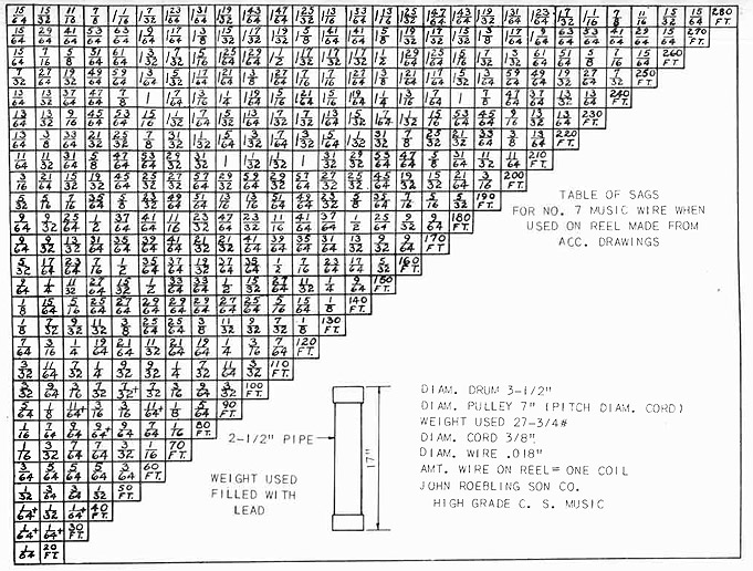
APPENDIX V
Using The Sag Table
The sag table given on page 297 is applicable in all cases where the
target stands for supporting the tight line are spaced 10 feet apart.
Where the total length of the tight line exceeds a distance which can
be equally divided by 10 it is permissible to find the center between the
two extreme tight line supports and to work both ways from the center for
the location of the target stands.
The two end distances may be slightly more or less than 10 feet.
For example: The total distance maybe 172 feet from the extreme supports
of the tight line. Working from the center both ways gives fifteen spaces
exactly 10 feet apart. The two end spaces will be eleven feet. The 170
FT. horizontal row of figures in the table will be used and the sag
blocks will be placed on the target stands in the relative positions given
in the table.
The sag in the tight line for eleven feet at each end is .01546
or .0014 more than in ten feet. A .0015 shim may be placed under each
sag block in every target which will support the tight line as close
as necessary for all practical purposes.
The example given above illustrates the procedure only in an emergency. Usually the target stands can be placed to have 10' between
centers. Sometimes the last target stand may have to be placed a few
feet further along than is required to obtain a measurement which is a
multiple of 10 feet between the two extreme target stands.
When the distance is a multiple of ten feet refer to the sag table.
Assuming that this length is 110 feet the horizontal line in the table
which is marked 110 FT. is the line to use.
Ten sag blocks are required. The two outer sag blocks are 3/32"
thick. The next two sag blocks are 11/64" thick. The third pair of
sag blocks measures 7/32"; the next pair measures 1/4"; and finally the
two center blocks measure 9/32".
The same size wire, .018, must be used at all times in connection with
the figures given in this table. The same weight, 27-3/4 lbs. must
also be used. It is desirable to use a 3/8" cord for the weight. A
heavier cord is likely to be a little stiff and also adds slightly to
the weight.

 " at the upper end of the center line mean
"Center Line" on any blueprint. When beginning to lay out the work
for any job, always find or locate a center line from the blueprint
and then take all other measurements from the center line.
" at the upper end of the center line mean
"Center Line" on any blueprint. When beginning to lay out the work
for any job, always find or locate a center line from the blueprint
and then take all other measurements from the center line.
 .
.

 means a section taken through this way,
looking the way the arrow points
means a section taken through this way,
looking the way the arrow points is a symbol for diameter.
 --Base line
 --Finish
 --Plate
 -Midship section