OUTSIDE MACHINIST TRAINING
ADVANCED WORK AND MAINTENANCE
90
This Page Blank.
91
PART II
Using a Portable Grinder
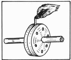
PURPOSE OF A PORTABLE GRINDER
A portable grinder is used, wherever possible, to expedite the work
of the outside machinist. Uneven surfaces on foundations, rough edges
on plating, excess stock on chocks, and rough spots on decks or bulkheads are ground smooth with the portable grinder.
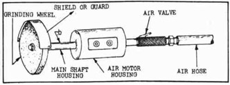
Fig. 126--Portable Grinder
THE AIR MOTOR
The tool is driven by an air motor which receives a steady supply
of compressed air through a heavy rubber hose attached to the handpiece
of the grinder. Fig. 126 shows an air valve at "a" between the housing and the air hose. The position of this air valve makes it easy for
the operator, by a touch of the thumb, to admit or cut off the air instantly.
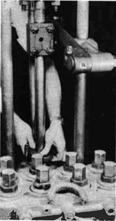
OPERATING THE GRINDER
When grinding, the operator must keep his hand on the air valve
constantly; for when the valve is released, the wheel stops.
The other hand is placed to grasp the neck between the grinding
wheel and the motor housing at "b" to guide the machine over the work.
After a little practice, the operator will discover the correct way to
stand to hold a balance and guide the grinding wheel.
When using the grinder, the operator does not need to "lay on" the
machine to make it grind. If too much weight is applied, the wheel will
slow down and consequently less work will be accomplished. A steady,
even pressure while the machine is kept moving slowly back and forth
will remove stock quickly and do a smooth job.
GRINDING WHEELS
The grinding wheels used are about 1-1/4" to 1-1/2" thick and 6"
to 8" in diameter.
Be careful to use a wheel of the correct grade and grit for the
job. The grade of wheel used for steel is not generally used for cast
iron. Check with the leader about the correct grade of wheel to use.
92
CLEARING THE LINE
Before attaching the air hose, clear the line by turning on the
air at the main valve. This will blow out any dirt or water that may
have collected in the line. If the motor slows up or sticks, the
application of a little light machine oil will clear the valves. Disconnect the air hose from the hand-piece, replace the air hose and blow
out to clean the mechanism.
SAFETY PRECAUTIONS
When the grinder is laid down on the deck, never move the air control valve. To do so may cause the machine to roll around and possibly
drop through an open space which could result in serious injuries to
others.
Never hook up a machine and then raise or lower it by means of the
air hose. The coupling could let go, or the air hose might break;
either could have serious results.
MAKING REPAIRS
Never attempt to take a portable grinder apart if it seems to need
repairing. Such work is always done in the tool room by experts. Report to the leader at once if the machine fails to work properly.
QUESTIONS
1. Name a few jobs where a portable grinder is used.
2. Why is the machine called a "portable grinder"?
3. How is the action of the air motor controlled?
4. Where does the operator place his hands when he is using a
portable grinder?
5. Explain how the line is cleared before the air hose is attached.
6. Who makes the decision regarding the correct type of wheel
for the job?
7. Explain how the operator can control the grinder to make
it work best.
8. Name a few safety precautions which should be observed
when using a portable grinder.
9. What should be done when it seems that the grinder needs
repairing?
Fitting Chocks
PURPOSE OF A CHOCK
The installations aboard ship, such as electric motors, turbo-generator Gets, cargo pumps, etc., must be bolted down to the deck plate
or support provided by the ship erector. All this machinery has to be
lined exactly with the centerline of the ship and, within certain limits,
level, as the ship rides normally. As the decks and foundations are not
exactly level or "fair", some method has to be employed to make the machinery level and true.
93
LOCATION OF CHOCKS
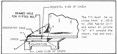
Rectangular blocks, usually cast iron, are placed between the somewhat irregular and uneven surface of the foundation on which the equipment is to be placed and the base or pedestal of the equipment installed. The full weight of the equipment is distributed among supporting chocks,
which must therefore be carefully fitted so that when the ship is riding
in the water, vibration will not cause the chock to move and the equipment to shift and lose its alignment. The shape of a chock and the
manner in which it is used are shown in Fig. 127.
Fig. 127--Fitted Chock Between Base and Foundation
SAFETY
Watch the movements of other workmen to avoid injury to them or to
yourself.
Take care of the tools and equipment in use on the job, so that
they do not fall and injure some other workman.
Be careful not to trip over the many cables, hose lines, and other
pieces of equipment which are always found around the job.
1. Line up the motor, pump, or other equipment, using steel blocks
and wedges under the pedestal. Check with the level and declivity board on some machined surface of the unit being installed.
Adjust blocking until the unit is level.
94
NOTE: Large, heavy jobs require the use of jacking screws or
blocks and wedges to move the unit sidewise or endwise.
(The jacking screws are welded to the deck and burned
off after the job is finished.) Jacking screws are also
used to move the heavy jobs up and down.
The holes that are in the base of the unit may be
tapped, or a hole may be drilled in the base and tapped.
A large set screw and a half nut may then be used to
jack the unit up and down as required.
(When the job is ready for the installation of the
hold-down bolts and the location of these bolts comes
in a tapped hole, the hole must be re-drilled in order
to remove the thread in the tapped hole. It is always
difficult to fit a bolt tightly through a threaded hole.)
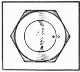
2. With the unit set correctly, drill the deck or foundation for
hold-down bolts by lining up the drill in the air drill machine
through the hole already in the pedestal. Use an "old man" to
steady the air drill machine.
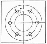
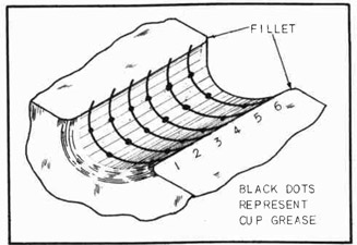
3. Measure from the under side of the pedestal to the foundation,
one corner at a time, beginning with corners "a-a" at the left
side. See Figs. 127 and 128.
NOTE: Measure the distance with inside calipers, and read the
measurement in 64ths on the scale. See Fig. 22.
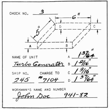
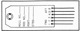
Fig. 128--A Conventional Chock Sheet
4. Continue measuring from the under side of the pedestal at
points "B","C", and "D", shown on the chock sheet. Do this with
95
each chock location, and fill out a chock sheet for each chock.
Give the size of the chock, the name of the unit under which
the chock is to be fitted, the number of the ship, and the
charge number. Blank spaces are provided on the chock sheet
for this information. Sign the sheet, giving name and clock
number.
NOTE: Number the chock sheets with pencil and the chock locations with paint as soon as each measurement is completed.
5. Send the chock sheets and the chocks to the machine shop, where
each chock is cut to approximate size, numbered, and returned
to the job.
6. Proceed to fit the chock as follows:
(a) Check the chock for size before starting to fit. (Sometimes chocks are spoiled by too much machining in the shop.
Do not waste time trying to fix such chocks. Return them
to the machine shop to be worked over for another location
where a thinner chock may be used.)
With the portable grinder, carefully rough-finish the
surface of the chock which rests on the deck or foundation.
(This side is called the land side.)
(b) Chalk the land side of the chock.
(c) Slide the chock under the pedestal. The high spots will
show up. Slide the thinnest side of the chock under first.
Mark the position of the chock to make sure that the fitting is being done in the same place each time. Try feelers at intervals.
NOTE: Since the top side of the chock is a finished surface to
contact the finished surface of the underside of the machine base, under no circumstances is the pedestal side
to be ground or filed. A portable grinder may be used
to remove the high spots from the land side when there
is too much to file.
After the mechanic has fitted a few chocks, experience will guide him in future fittings.
(d) Place the chock on a suitable support, and file high spots
with a 12" or 14" flat or square bastard file.
(e) Try the chock in place to cause the high spots to show up,
as before.
NOTE: Repeat this operation until the chock fits almost all
the way in.
(f) Finish-file with a 12" or 14" flat mill file.
NOTE: The chock must fit so that a .0015 to .002 feeler will
not enter the joint on either top side or land side.
(g) With the chock fitted correctly (check with the leader),
proceed as follows:
(1) Drill the hold-down bolt hole through the chock.
96
(2) In some cases the chock is carefully held in the
correct location and the outline of the hole is
scribed on the chock.
(3) The chock is then removed, the hole outline is marked
with the prick punch, the center is marked with the
center punch, and the job is sent to the machine shop
for drilling.
NOTE: When the machinist is fitting generator chocks, he
fits the four corner bolts for driving in. The four
corner holes in the unit being installed are reamed
after drilling. In some cases the chock is reamed
at the same time. Ream the holes to the size shown
on the blueprint. The bolts are turned .0025
larger than the hole, for a drive fit.
All other holes are drilled to size, and black
bolts usually are large enough to drive in without
fitting. Bolts which are secured from the store
room and which are not turned to size are called
"black bolts" because they are not polished, but
are used in the same condition in which they are
received from the manufacturer.
(4) Drive the special bolts into place, and draw the nuts
down securely.
NOTE: When the machinist is fitting pump chocks, he drills
the holes to size. Black bolts are usually found
to be a snug fit.
(5) Check fit with .0015 feeler, between chock and floor
plate or foundation, and between chock and under side
of pedestal.
NOTE: In some instances after the unit is installed and the
chocks fitted and bolted down, dowels are installed
in opposite corners. See Fig.275. This is done
only where fitted bolts are not used. Check with
the leader for instructions.
QUESTIONS
1. Why are chocks required under the base of a unit being
installed?
2. Explain how a unit should be leveled before the holes are
drilled in the foundation.
3. For what purposes are dowels used in the base of the unit?
4. State the correct procedure for installing the dowels.
5. Under what conditions are dowels not necessary?
6. How close should the fit be between the chock surface and
the unit base; the chock surface and the foundation?
7. Where are fitted bolts used when installing a unit?
8. How are the high spots indicated on a chock?
9. How much larger than the hole should the fitted bolt be?
10. Explain how to use a chock sheet.
97
*Using Gasket Material and Thread Dope
TYPES OF PACKING
In mechanical work it is of paramount importance that exactly the
right type of packing be used for each individual application or job.
Temperature, pressure, and the action of the liquid material contacted
have to be considered. Many types and brands of packing are listed in
supply catalogs. No attempt is made here to judge any one brand to be
better than any other. Where gaskets are used, the surface of the metal
should be thoroughly clean.
SPECIAL MATERIAL
Red gum or rubber packing is used extensively in low pressure water
lines working under low temperatures. 1/8" thickness is by far the most
commonly used. 1/16" thickness is available and may be used in joints
where the flanges are too close together to admit 1/8" thickness. Greater thickness than 1/8" is never satisfactory either as a ring joint or
a full joint. One word of caution--if the bolts are pulled excessively
tight, the packing flattens and creeps out, protruding all around the
flange edges. Since the packing is meant for low pressure work, such
excessive tightening is not called for, and this condition need not
occur.
Wire inserted rubber packing and cloth inserted rubber are excellent in water pipes working under high pressure or hot temperatures. The
cloth inserted type makes a good gasket for a shell-of-the-ship joint
such as an overboard discharge valve or a clapper valve. The wire and
the cloth give the packing a sturdy base, and it will stand extreme
tightening without creeping.
COMPRESSED PAPER PACKING
For oil piping a compressed paper gasket material is used, such as
hydraulic or kidskin packing. This type of packing, as well as rubber,
is also used in low pressure water lines. It may be used as a ring or
a full joint and is easily cut with a pocket knife. It will stand any
amount of tightening. The paper comprising the construction of this
packing is in thin layers.
SHEET STEAM PACKING
In low pressure steam lines, a great number of brands of sheet steam
packing are carried in stock, any of which are satisfactory. Order without using the brand name: for example, 1 piece of steam packing, thickness by width by length. One-sixteenth thickness is preferred in joints
that face squarely and are not pitted. 1/16" cuts easily with a pocket
knife. Steam joints should be graphited to prevent the gasket's sticking
to the flanges. Heat from the steam after some time causes the gasket
to stick so tightly that it will tear if the joint is disconnected and
will be difficult to clean off.
Steam packing that has been treated with graphite lubrication can
be obtained. In the majority of cases in low pressure lines, however,
plain sheet steam packing is used; and flake graphite, mixed with linseed oil, is applied to each side of the gasket before inserting between the flanges. This graphite lubrication should also be applied to
the bolt threads to prevent welding of the bolt and the nut from heat.
98
In high pressure steam lines more care must be exercised in selecting the type of packing to use. Most high pressure flanges have bosses
which necessitate the use of ring joints. See Fig. 130. Only the highest
grades of sheet steam packing should be used.
FLEXATALLIC GASKETS
Flexatallic gaskets must be purchased ready made. They consist of
an asbestos ring covered with a thin metallic composition. On two sides
a thin, narrow strip of the metal extends out far enough so that two of
the flange bolts pass through it and hold the gasket in place. These
gaskets are used on high-pressure, super-heated steam lines.
METALLIC GASKETS
Metallic gaskets are ready made to fit. There are different makes,
the majority of which are corrugated ring joints. Their use is sometimes specified for high pressure steam lines. (Metallic gaskets are
used in diesel engine starting air lines where the pressures are very
high.) Garlock metallic gaskets are used exclusively in some shipyards.
ASBESTOS SHEET
Asbestos sheet packing is an excellent heat resistant. Different
compounds of asbestos are used extensively in superheated steam lines.
The exhaust piping from diesel engines requires asbestos sheet packing
because of its high working temperature. This packing is obtained in
sheet form, ready made ring joints, or full joints.
Refer to Crane Catalog No. 52 for information on gasket material.
SUGGESTIONS IN CONNECTION WITH THE USE OF GASKETS
1. Be careful when using a ring joint between cast iron flanges
because the flanges may crack if the bolts are pulled too
tight.
2. Do not use a ring joint between two thin flanges because they
will dish if the bolts are pulled too tight.
3. Do not use a ring joint in brass flanged joints because the
brass flange dishes quite easily. Use full joints.
4. Do not use a ring joint where the flanges are exposed to the
weather, such as on deck. Rust will soon form in the space
from gasket edge to flange edge and deeply pit the flange.
5. Do not use a ring joint where studs are used if there is any
pressure on the back end of the studs, that is, watertight
bulkheads.
6. Use ring joints extensively in all places not exempted above
because they tighten more readily and hold tight better than
full joints, eliminating danger of leaks around the bolts.
THREAD AND GASKET DOPE
A mixture of a small amount of red lead powder with one bottle of
gaskalac forms the most commonly used thread and gasket dope. The red
lead powder acts as a base, makes the mixture firmer, and causes it to
dry more quickly. When used on threads, the solution reduces friction
of metals and allows the joint to be pulled tight. It also seals the
Joint watertight when it hardens.
99
RED LEAD PUTTY
To a quantity of white lead, add red lead powder until the desired
consistency is obtained. The more powder used, the thicker the mixture
becomes. This dope has many uses, such as seating commodes, doping
grommets and gaskets on shell-of-the-ship joints, and putting gaskets in
rough surface joints where the pressure does not exceed 15 pounds.
LITHARGE AND GLYCERINE
In some shipyards, all thread joints are doped with expando exclusively. This comes in the form of powder and is mixed with water.
Litharge and glycerine is a quick-hardening mixture and should be prepared for immediate use. It is used extensively in ice machine, ammonia, and fuel oil fittings. Pour glycerine into a small, clean container, and "stir in" desired quantity of litharge. Have joints perfectly grease-free and clean. Apply freely to male thread and tighten
quickly before the mixture hardens, Moving the fitting after this mixture hardens ruins the joint.
KEY PASTE
Key paste comes ready-mixed in red and blue tubes; one color of
tube is for threads, and the other color of tube is for gaskets. These
mixtures are used in brass fittings and are recommended by the U.S. Navy.
WHITE LEAD
White lead paste is often used on the gasket in shell-of-the-ship
joints. Caution: Because it is Poisonous, white lead should be placed
only on the male threads of connections that carry drinking water.
When heating connections close to the thread, as on short bends, use
white lead freely on the pipe thread and in the fitting, except drinking
water fittings, so that the thread will not tear when unscrewed.
SMOOTH-ON
Smooth-On is an iron cement used for patching broken castings as
well as for joining new, old, or worn fittings. It should be used only
on low pressure fittings. It comes in powder form and is mixed with
enough water to form a paste. Joints must be thoroughly cleaned before
applying the mixture. Three or four hours should be allowed for the
mixture to harden before pressure is turned on.
QUESTIONS
1. Name some of the different types of packing used in shipyard work.
2. Red gum or rubber packing more than 1/8" thick should
never be used. Explain why.
3. Where is compressed paper packing used?
4. What type of packing is used for steam lines?
5. Explain why ring gaskets should not be used under certain
conditions.
100
6. Under what conditions is red lead putty used?
7. Where is white lead used?
8. State the qualities of a litharge and glycerine gasket
dope.
9. Where is key paste used?
10. Explain where and how Smooth-On is used.
* Adapted from "Shipyard Outside Machinist" by State Department of Education, Alabama.
*Making a Full Face Gasket
INFORMATION
A gasket is a ring or disc of packing used to make a flanged joint
tight against leakage. See Fig. 129.
TOOLS
1. Machinist hammer
2. Pocket knife
MATERIALS
Flange
Gasket material
Fig. 129--Cutting Holes with a Hammer
PROCEDURE
1. Lay flange face up and cover completely with gasket material.
2. With the pressure of the thumb, locate a hole in the flange.
3. With the ball head of hammer, tap the gasket material over and
around the edges of one hole, making the hole edges in the
flange cut the material.
4. Place a bolt in this hole so that it will not slip out of
place. See "a", Fig. 129.
5. Locate and cut the opposite hole.
6. Place a bolt in this hole to prevent the gasket material from
slipping. See "b", Fig. 129.
7. Locate and cut the remaining holes.
8. With the flat head of the hammer, tap the material over the inside and outside edges of the flange, tapping only hard enough
to make the flange edges mark the material.
9. Remove material from flange face and cut the outside circle
as marked.
101
10. Cut the inside circle approximately 1/8" smaller than the mark.
This is to cover the thickness of the pipe wall where it comes
flush with the face of the flange. If the pipe is extra heavy,
the hole should be cut approximately 1/4" smaller.
QUESTIONS
1. Do the holes and edges of the gasket correspond exactly to
the holes and edges of the flange face?
2. Why must the gasket fit perfectly?
3. When are standard gaskets used?
4. Where are standard gaskets obtainable?
5. What tool is used to trim gaskets to size?
6. State the usual thickness of gasket material.
7. Explain the difference in the materials from which gaskets
are made.
8. What happens when a flange joint is pulled up tightly on a
gasket that is thicker than necessary?
* Adapted from "Shipyard Outside Machinist", by State Department of Education, Alabama.
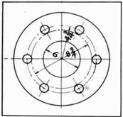
* Making a Ring Gasket for a Standard Six-Inch Flange Joint
INFORMATION
Ring gaskets should be used wherever possible. See Fig. 130. They
tighten more readily and hold better than full face gaskets, eliminating
the danger of leakage around the bolt holes. The instructor will explain the reason for this.
The outside diameter of the ring gasket should equal the diameter
of the circle made by the inside edges of bolt holes. The center hole
diameter should equal the center hole diameter of the pipe used.
Fig. 130--A Ring Gasket
Bolt Circle is 9-1/2 inches Diameter Bolts are 3/4" Diameter Outside Diameter of Ring Gasket is 8-3/4 Inches Inside Diameter of Ring Gasket is 6 Inches
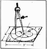
Fig. 131--Laying Out a Ring Gasket
TOOLS
1. Dividers
2. Rule
3. Pocket knife
MATERIALS
Gasket material 9" x 9"
102
PROCEDURE
1. Open dividers until they measure 4-3/8" between points.
2. Place one point in center of material and press down so point
will not slip.
3. With other point, mark a circle on the material 8-3/4" in
diameter. See Fig. 131.
4. Close dividers until they measure 3" between points.
5. Using same center, mark another circle on material 6" in
diameter. See Fig. 131.
6. With the pocket knife cut out the gasket as marked.
QUESTIONS
1. Does the center hole of the gasket fit the center hole of
a standard 6" pipe?
2. Place the bolts in the holes of the 6" flange. Does the
gasket fit snugly within the circle of the bolts?
3. State the places where a ring gasket should not be used.
NOTE: In many shipyards, standard size gaskets may be obtained from the store room. These gaskets fit all
standard jobs. There are some jobs that are not
standard. In such cases a special gasket must be
made.
* Adapted from "Shipyard Outside Machinist", by State Department of Education, Alabama.
* Cutting a Dovetail Gasket
INFORMATION
There are times when a gasket must be installed without removing
a shaft from the bearings. Suppose a gasket has to be renewed for some
reason, for example, where a shaft passes through a watertight bulkhead.
This may be done without tearing down any part of the unit except to
remove the bolts' from the flanges and slide the flange back. In this
case the gasket is "dovetailed" to slip over the shaft. See Fig. 132.
TOOLS
1. Outside calipers
2. Knife
3. 6" scale, or longer if necessary
4. Machinist's hammer
5. Dividers
6. Pencil
The Dovetail Is Cut In a Standard Gasket of the Correct Diameter
Fig. 132-A-Dovetail Gasket
103
PROCEDURE
Fig. 133--Installing a Dovetail Gasket
1. Measure the inside and outside diameters for the gasket.
2. Obtain a standard gasket from the storeroom.
3. Lay the gasket on a flat surface and find the center with the
dividers.
4. Lay one edge of the scale on the center, and scribe a line
across the diameter of the gasket.
5. Lay off a dovetail at one side of the diameter as shown in Fig.
132.
6. With a sharp knife cut the dovetail through accurately. See
that there are no ragged edges.
7. Now slip the gasket over the
shaft and close the dovetail in
place.
8. Use a machinist's hammer to locate the bolt holes.
NOTE: If there is not enough
room to use a hammer, lay
out the bolt-hole circle
and carefully space the
holes. Scribe the hole
circle with the dividers,
and cut out with a sharp
knife.
When cutting out the
bolt holes, obtain gasket
punches from the tool
room. These punches cut
a nice, clean hole. Be
sure to have the punch
exactly on the spot where
the bolt hole is to go
through before striking
with the hammer.
Try the gasket in place and put the bolts through
the holes to make sure everything fits. Be sure the
dovetail fits correctly.
9. Push the flange back into place, install the bolts, and tighten
securely.
*Adapted from "Shipyard Outside Machinist", by State Department of Education, Alabama.
104
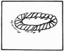
* Making and Installing a Grommet
INFORMATION
Grommets are used as gaskets to make a tight joint around bolt or
stud holes. They are made of lamp wick. When placed around a bolt or
stud and under a washer, they squeeze tightly into the space around the
bolt when the nut is pulled tight. In making shell-of-the-ship or bulkhead joints, it is common practice to paint the grommet with white lead
or red lead putty. After hardening, the lead gives an additional assurance of a sealed joint.
Where bolts are used, grommets (made as per sketch) are used only
on the threaded end. Grommets for the head end are made by wrapping the
proper length of wick around the bolt after washer has been placed on
bolt. The length of the wick is determined by the size of the stud or
bolt, for example:
for 1/2" cut off 18" of wick
for 5/8" cut off 24" of wick
for 3/4" cut off 30" of wick
TOOLS AND EQUIPMENT
1. Rule
2. Pocket knife
MATERIAL
Ball lamp wick
and
stock grommets
PROCEDURE (If grommets are made on the job)
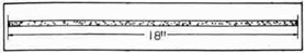
Fig. 134--Length of Lamp Wicking
1. Cut off 18" length of
wick.
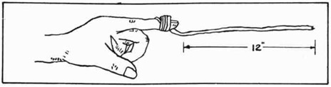
2. Wrap wick around forefinger 2 to 4 times,
depending on size of
bolt. The remaining wick will be about 12" long.
Fig. 135--Wrapping Wicking Around Finger
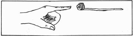
Fig. 136--Loops Removed From Finger
105
3. Slip the ring off the finger. See Fig. 136.
4. Pass end of wick through ring until the circumference of ring
is completely covered. See Fig. 137.
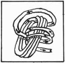
Fig. 137-Covering Loops
Fig. 138--Finished Grommet
5. Pull the wick tight so that the grommet will not be lumpy.
See Fig. 138.
NOTE: In some shipyards a full line of grommets is carried in
the storeroom. In this case it is unnecessary to make
grommets by hand. Fill out a requisition, and after the
leader approves it, present it at the storeroom.
QUESTIONS
1. For what purpose is a grommet used?
2. How is a grommet prepared to make sure it is leak-proof?
3. When are hand-made grommets required?
4. Is it possible to use a grommet the second time? Explain.
5. What happens if the grommet is lumpy and does not pull
down evenly?
*Adapted from "Shipyard Outside Machinist", by State Department of Education, Alabama.
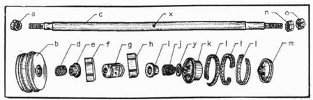
Packing a Stuffing Box
GENERAL INFORMATION
A stuffing box is necessary to prevent leakage of steam, oil, or
water around such places as a steam valve shaft, a deck stand operating stem, or a circulating pump shaft. In most cases packing must be
placed after the unit is installed with the shaft in position. In
other cases the packing is already in place, but must be checked to
make sure there is no leakage.
TYPES OF PACKING USED
Many types of packing are used. One type of packing looks much the
same as another type, and care must be exercised to make no mistake in
selecting the correct type.
The usual practice is to use:
1. Flax packing on water cylinders.
2. Semi-metallic packing on valve rods and piston rods(steam)
106
3. Graphited, long-fiber asbestos on fuel oil pump piston rods.
Always check with the leader to avoid errors.
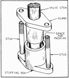
Fig. 139--Stuffing Box Assembly
Packing comes in long strips, usually in coils shaped like a closed
spring. The packing may be
round or square in cross-section. The square packing is
used to better advantage, in
most cases, because it conforms
to the shape of the stuffing box
more closely.
Fig. 139 shows a typical
pump stuffing box and gland.
The gland is the piece that is
pressed into the stuffing box
by means of bolts and nuts.
Pressure causes the packing to
squeeze tightly against the
shaft and prevent leakage.
TOOLS AND EQUIPMENT
1. Open end wrench
2. Pocket knife
3. Packing hook
MATERIALS
Packing
GENERAL PROCEDURE
(a) When using single rings cut from coil
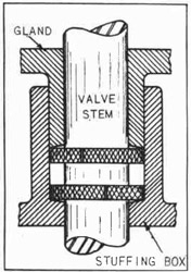
Fig. 141--Packing in Place
1. Measure distance between the wall of the stuffing box and
outside of gland.
NOTE: When the mechanic is
packing a box by this method,
he should cut the packing
slightly short, to prevent
butting the ends and buckling
them. See Fig. 140.
Each ring should be inserted
and pushed as far into the box
as possible with the gland.
See Fig. 141.
The split or joint of the following ring should be staggered, to prevent a blow-by
channel. See Fig. 142.
When the box is full, press
the packing rings down with
the gland and start both nuts.
See Fig. 143.
Fig. 140-Single Ring
Fig. 142 Staggered Joints
107
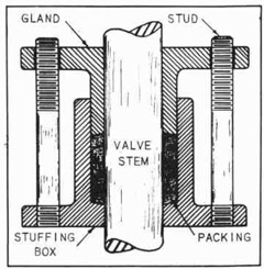
(b) When using packing cut in one piece from coil
Fig. 143--Cross Section of Packing
1. Find the outside circumference
of the box, and cut off one
piece of packing long enough to
fill the stuffing box completely.
Fig. 144--Pushing Packing
2. Start one end of the strip of packing and carefully coil it
around the stem of the valve or piston rod, using the packing
hook (dual purpose), a wooden stick, or the gland, to press the
packing into the space evenly.
3. When the box is full, slide the gland down. See Fig. 144.
Using a little pressure, start both nuts.
4. Tighten each nut a little at a time, keeping the tension uniform to prevent cramping the gland do the stem, and so prevent
misalignment and undue wear.
5. Check with the leader for his approval.
STUFFING BOX PACKING MAINTENANCE
Keep boxes well filled with a good quality packing. Screw the
glands down at first just enough to prevent leakage. When the packing
has become adjusted to the shaft under working conditions, the gland
may be tightened further to prevent leakage.
Repack the stuffing boxes before the packing becomes so hard that
it will score the rod.
NOTE: The correct amount of packing to use is best learned by experience. Check with the leader the first few times to make
sure the job is being done correctly.
QUESTIONS
1. Why is it important to put as much packing as possible
into a newly packed stuffing box?
2. What is the purpose of a stuffing box gland?
3. State how the measurements of a stuffing box are taken to
get the size and length of the packing strip.
108
4. What tools are used when packing a stuffing box?
5. Explain how the mechanic knows when the gland is pulled
down tight enough.
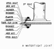
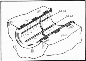
* Making a Watertight Joint
INSTALLING A GASKET AND GROMMETS
When tanks are filled with liquid, pressure is exerted on all sides.
If at any time a pipe connection is below the level of liquid, there is
danger of leakage around bolts or studs. For this reason gaskets are
used on each side of each stud hole. These gaskets are made of lamp
wick and are known as grommets. See Fig. 145.
Washers are used to press them down watertight. In some cases,
such as shell-of-ship joints, the grommets are painted with red lead
putty.
In Fig. 145 a 3" vent is shown flanged to the top side of a small
tank. It is taken for granted that holes have already been drilled and
tapped, and that the studs are in place.
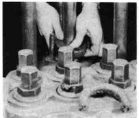
2. Take four grommets, four
washers, four nuts, and
5/8" wrench, and go inside
tank.
3. Put a grommet, then a washer, then a nut on each stud;
and pull nuts down tight.
See Fig. 145.
4. Come outside tank, and place
gasket and flange in position.
5. Place grommet, washer, and nut on each stud; and pull nuts down
tight. See Fig. 145.
QUESTIONS
1. Why is a washer placed between the nut and the grommet?
2. What happens to the grommet when the nut is pulled down
tight?
3. Why is a full-face gasket used between the flange and tank?
109
4. What is the reason for using "dope" on a grommet before
placing the steel washer and pulling the nut down?
5. Would it be practical to make a watertight joint without
the use of grommets?
*Adapted from "Shipyard Outside Machinist", by State Department of Education, Alabama.
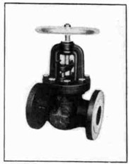
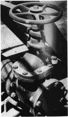
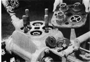
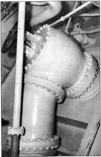
Overhauling a Valve
INFORMATION
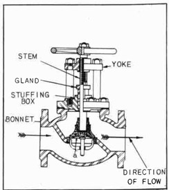
Fig. 146--Globe Valve
This job instruction sheet applies principally to globe and gate valves.
The many globe and gate valves of various sizes aboard ship must be overhauled
from time to time. The wearing and pitting
of globe valve discs and seats cause leaks.
Valve stems get bent, packing between the
bonnet and the valve body must be renewed,
old and worn stuffing box packing must be replaced, and possibly a scored stem may have
to be removed and a new stem installed. See
Fig. 146 for globe valve exterior.
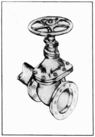
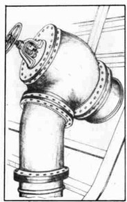
Fig. 147--Gate Valve
The glove valve seats must be ground to
a new fit after they have become worn. This
is not possible with gate valves, on account
of the wedge gate construction. If not
worn too badly, the seat ring and the disc
ring of agate valve may be scraped slightly to a new fit; but such cases are usually rare. New seat rings and new disc
rings are installed when a gate valve is
badly worn. See Fig. 147 for gate valve
exterior.
The work of dismantling and reassembling either type of valve is essentially
the same. Where, because of size, the
construction of valves differs, a slight
change in the use of the tools and the
handling of the valves will necessitate
departures from the procedure as outlined
below. The illustrations of the valves
given in this instruction sheet are typical. The details may vary slightly according to the valve manufacturer's specifications.
TOOLS AND EQUIPMENT
Regular tools
MATERIALS
Globe or gate valve
Gasket material
Stem packing
Grinding compound
110
Fig. 147-A--Reassembling a Globe Valve
PROCEDURE
1. Secure the proper size of wrench, and remove nuts from bonnet
studs.
2. Mark bonnet and valve body for replacement identification.
Remove bonnet by turning stem hand wheel in the direction
marked "closed" on the wheel until the bonnet flange rises
free of the valve body.
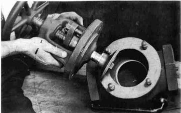
3. Lift bonnet, with stem and disc assembled, from the valve body.
If the bonnet is "frozen" to the valve body, use fox-wedges
to start the bonnet. The knife edges of the wedges must be in
good shape. Start the wedges evenly, all around, until the
bonnet breaks loose. This step applies especially to large
valves.
NOTE: After the bonnet assembly has been removed from the
valve body, check the flange faces on the bonnet and on
the body for misalignment, scores, and battered places.
Use a surface plate, a straight edge, or some other
level surface as a guide in checking. A close inspection will reveal whether or not it is necessary to send
the job to the machine shop for re-conditioning.
4. Remove nut or pin from the stem and remove the valve disc.
5. Test the valve seat by sounding with a small hammer or the
head of a chisel. Use care not to scar the valve seat.
6. If the seat is found to be tight in the valve body and neither
the seat nor the disc is scarred too badly, replace the disc
in position on the valve seat to "grind in" with grinding
compound. Grind valve as per instructions in Grinding Valve
Seats. (Page 113.)
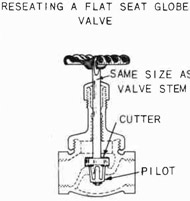
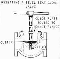
7. Examine the seat for a groove or shoulder. If the seat is
"grooved" or "shouldered", it will have to be refaced in the
machine shop or with a valve-reseating machine. See Figs.
148-A and 148-B.
111
Fig. 148-A--A Flat Valve Seat Refacing Tool
Fig. 148-B--Bevel Valve Seat Refacing Tool
NOTE: Look for poor fits caused by too deep a seating of the
valve disc on the valve seat, too wide a contact between
the valve disc and the valve seat, or a bent valve stem
which allows the valve disc to seat on one side only.
8. Install the new valve seat at this point. Seat the disc by
"grinding in". Check with the leader for his approval.
9. Remove the old packing from the valve stem gland and replace
with new packing. Pull packing gland down tightly.
10. Examine valve stem bonnet studs and nuts for deterioration, bad
threads, or fractures. Replace any that are found defective.
11. Make a new gasket for the bonnet, using the old gasket or bonnet flange for template.
12. After the valve disc is on the stem and secured in place with
nut or pin, make sure that the disc will float on the stem to
allow for proper seating. See Fig. 147-A.
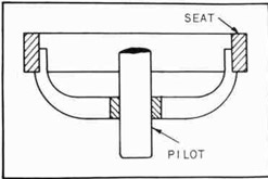
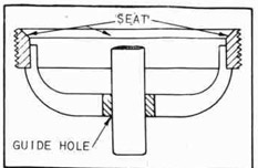
13. Replace bonnet in original position. Be careful that the pilot
of the disc enters the guide hole in the center of the seat.
14. Turn the valve stem wheel toward the "open" position until the
disc leaves the seat and the flange of the bonnet comes in contact with the flange of the valve body.
15. Replace the nuts and tighten evenly by going around with the
wrench several times.
16. Turn the valve stem wheel toward the "closed" position until
the disc comes in contact with the valve seat.
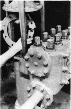
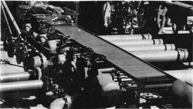
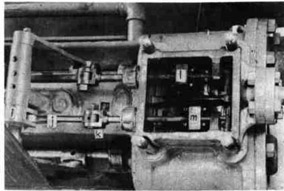
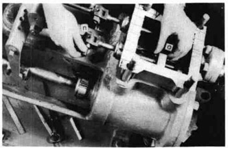
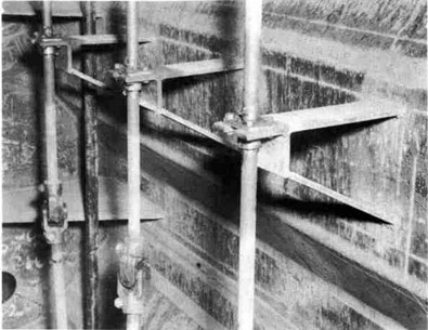
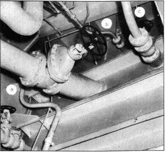
Figure 149 shows a group of gate valves which are used in the
liquid cargo lines. The mechanic usually brings his tools to the location of the overhaul job and performs his work there. This procedure
eliminates the possibility of losing valve parts which would likely
happen if they were carried away from the job to be worked upon elsewhere.
112
Fig. 149--A Group of Gate Valves on the Weather Deck
QUESTIONS
1. State some of the reasons for overhauling valves.
2. What is the correct procedure to follow when a globe valve
seat and valve disc are badly scored?
3. When a gate valve leaks how may the valve seat ring and
disc ring be brought to a correct fit?
4. Explain the principal difference between a globe valve and
a gate valve.
5. What is the purpose of a valve bonnet?
6. Name the four important parts of a globe valve.
7. If a globe valve seat is scored, is there any way it may be
refaced without removing it from the valve? Explain.
8. Point out the correct method of testing a valve seat to
discover if the seat is solidly in place or if it must be
replaced.
9. Explain what is done with the gasket and the packing when
overhauling either a gate valve or a globe valve.
10. What is the chief purpose of the pilot on the bottom side
of a bevel valve seat?
11. State the probable result if the valve bonnet is replaced
in an opposite direction from the original position.
12. Where are fox wedges used when overhauling a valve?
113
Grinding Valve Seats
INFORMATION
Fig. 150-Pressed-in Valve Seat
A valve can be used for only a certain length of time before the
working faces must be reconditioned.
Grit, corrosion, and friction cause
pitting and grooving. When this
condition gets to a point where the
valve leaks, it must be refaced by
grinding.
Fig. 151-Screwed-in Valve Seat
This operation is very similar
to grinding automobile valves. Some
valve seats (see Fig. 150) are
pressed into the body; and some (see
Fig. 151) are screwed into the body.
In either case, the valve seat may
be removed if replacement is necessary.
When the valve seat screws out,
a special tool is used to fit into
the lugs provided for this purpose.
When the valve seat is pressed into
place, a special puller is used to
remove the seat. Check with the
instructor for the correct procedure.
Make every move count. Be
sure of the correct thing to do before going ahead. A false move can
ruin a valuable piece of equipment.
TOOLS AND EQUIPMENT
Regular tools
(See leader)
MATERIALS
Used globe valve
Gasket material
Stem packing
Grinding compound
DISC END OF GLOBE VALVE
When the stem is turned down to close the valve, the valve "floats"
on the end of the stem and allows the valve to "seat" evenly all the way
around.
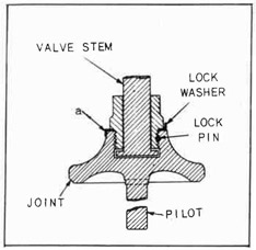
The lockwasher "a" is turned down on the disc on one side and turned
up on the nut on the opposite side. See Fig. 153.
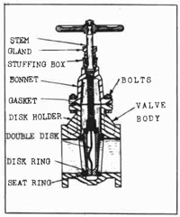
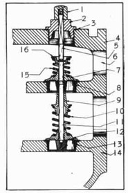
VALVE SEAT DISC
Figure 152 shows a typical globe valve cross section assembly.
Globe valve sizes are the same as the size of the pipe to which they are
bolted. For example: A 12" globe valve is used with a 12" pipe. For
114
Fig. 152--Globe Valve Cross Section
Fig. 153--Valve Seat Disc
diameters up to 12", measure the inside diameter of the pipe for the
size. The inside diameter of a 12"
pipe is 12.09 inches. The thickness
of the wall of the pipe is .33 inches. See table of pipe sizes in the
appendix.
The type of valve shown in Fig. 152 has a bonnet which is of flat
plate construction type with a yoke assembly secured to the bonnet with
studs. The bonnet is bolted to the valve body by means of these studs
and well-fitted hexagon nuts. The action of the mechanism in opening
and closing causes the valve disc to rise with the stem. A valve of
this type is called a globe stop valve. The valve disc is fitted to the
valve seat as follows:
(a) Apply grinding paste to the valve disc.
(b) Hold the valve disc firmly against the valve seat.
(c) With a circular motion, turn the disc back and forth on the
seat until a perfect joint is made between disc and seat.
(See Procedure for complete details.)
Figure 154 illustrates a typical gate valve with a raised bonnet.
The operating mechanism in a gate valve raises and lowers a wedge-shaped
gate which regulates the flow of steam, water, or oil. The raised bonnet provides a space into which the gate may rise when the valve is
opened. See Fig. 154-A. The bonnet must fit the valve body-flange perfectly. A gasket in the joint between flange and bonnet prevents
leakage.
PROCEDURE (Applicable in most cases.)
1. Remove bonnet, valve stem, and valve disk as instructed in
"Overhauling a Valve".
115
Fig. 154-Gate Valve Installation
2. Remove nut or pin from stem and remove the valve disc.
3. Test the valve seat by sounding with small hammer or the head of a cold chisel. Use care not to scar the seat.
4. If seat is found to be tight in the valve body and neither the seat nor disc is scarred too badly, replace disc in position on valve seat to "grind in" with grinding compound. Fasten the disc firmly to the stem by placing a thin washer or shim between the valve disc and the nut or fastening pin.
5. Seat disc to valve seat by smoothing grinding compound on the valve disc, press down firmly on seat, and "grind in" by turning valve stem backwards and forwards several times.
Fig. 154-A Gate Valve Cross Section
NOTE: Procure an "open coil" spring with sufficient tension to carry the weight of the valve stem assembly and to lift the valve from the seat during the grinding operation. Place the spring under the valve and allow the valve stem to drop through the inside diameter of the coils. Pressure will have to be applied to make the valve disc contact the valve seat.
6. Raise the valve disc after a few turns, and turn it to a new position on the seat. Continue "grinding" backwards and forwards as before.
7. Follow the procedure in Steps No. 5 and 6 until the valve disc has been turned one complete revolution. Some valves may need two complete revolutions to make the seat and disc fit perfectly.
116
8. Remove the disc, and wipe the compound from both the seat and
the disc. Examine for scars which may cause a leak.
NOTE: The grinding compound must be completely removed from
the valve seat and from the valve disc. Washing the surfaces with a liquid cleaner will insure a clean surface
and eliminate the possibility of any of the compound's
adhering and causing a score.
9. Examine disc for groove or shoulder. If one is found, the disc
will have to be refaced in the machine shop or with a valve-reseating machine.
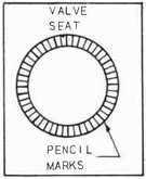
10. By marking the seat about every half-inch with a lead pencil,
test valve to see if it is properly seated. See Fig. 155.
Fig. 165--Checking the Seat
11. Replace disc to position on seat,
press down firmly, and turn valve
disc just enough to cut one line,
that is, turn the valve disc only
as far as the distance from one
pencil line to another.
NOTE: If marks are rubbed out all
around, the valve disc is
properly seated. Sometimes
the same procedure is
followed and prussian blue
is used instead of pencil
marks. Blue either the
valve disc or the valve
seat. Blue either one,
but not both.
12. Replace the valve disc on the stem and secure in place with the
nut or pin. Make sure that disc will float on stem to allow
for proper seating.
13. Check with the leader or inspector for his approval.
14. When the work is approved by the leader, proceed to re-assemble
the valve.
QUESTIONS
1. How is it determined whether or not the valve seat is
tight in the valve body?
2. If the valve seat is not tight, what is the correct procedure?
3. Explain how valve seats are taken out of a valve body.
4. State the reason for removing the valve seat from the
valve body.
5. If the valve disc is badly scored, what is the correct
procedure?
6. Why is it necessary to have a very narrow point of contact
between the valve disc and the valve seat?
117
7. Explain what happens when a valve disc pilot is a poor fit
in the valve seat guide.
8. State the correct method of checking the accuracy of the
fit between the valve disc and the valve seat.
9. When may a valve-reseating machine be used to good advantage?
10. Explain how valve-grinding paste, or compound, should be
applied and removed during the valve-grinding operation.
Setting a Valve
WHAT "SETTING A VALVE" MEANS
When the machinist is installing valves of various types, he must
give some attention to the position of the valve stem; the direction in
which the steam, water, or oil flows; the tension that he gives to
the bolts that hold the valve flanges to the adjoining pipe flanges or
other unit. The phrase "setting a valve" has nothing to do with the
opening or closing of the valve. When a valve is only slightly opened
it is said to be "cracked".
VALVE FLOW (Globe valve)
Figure 152 shows the direction of flow (arrows) through a globe
valve. Note the pressure of the flow 1s up and against the valve disc
"a". As the valve stem is opened up, the pressure of the flow is
against the valve disc. Always examine the valve carefully before setting it, to see which direction the flow is marked on the valve.
If the direction of flow is not marked, examine the inside of the
valve to see which end the flow enters to lift the valve disc. Then,
make sure of the direction of the flow through the pipe, or opening, to
which the valve is to be attached. When all the above has been determined, match the direction of flow through the pipe with the direction
of flow through the valve and bolt up.
VALVE FLOW (Gate valve)
Gate valves may be set either way because the direction of flow may
be either way. The only point to watch here is to see that the holes
in the valve flanges match the holes in the pipe flanges to which the
valve is to be bolted.
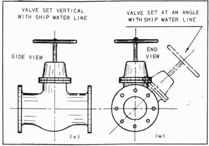
POSITION OF STEM AND HANDWHEEL
Valve stems are usually set vertically with the water line of the
ship. See Fig. 156 at "v". Other valves may be set at an angle with
the water line of the ship. See Fig. 156 at "w". Check the blueprint
carefully to make sure this setting is correct. Straight and angle
valves are always set according to the blueprint.
INSTALLING BOLTS
When the flange-to-flange joint is metal to metal, the bolts may
be drawn up as tightly as the bolt thread and nut will stand.
When a gasket is used between joints, the bolts can be drawn up
too tightly. Give every nut a little strain to draw the flanges up
118
evenly, and go over all the nuts several times until the gasket is firmly held, but not squeezed out at any point. A joint can be made to
leak if this part of the work is not watched very carefully. Check
with the leader for the proper bolt and nut tension.
Fig. 156--Two Ways to Set a Valve
The work sequence for setting valves is as follows:
PROCEDURE
1. Select the correct type and size of valve according to the
blueprint.
2. Examine the valve for direction of flow.
3. Check with blueprint to determine angle for setting the valve
stem.
1. Explain the direction of flow in a globe valve in relation
to the valve disc.
2. How is the correct setting of a valve determined in relation to the flow?
3. What is meant by the tension on the bolts?
119
4. State the probable cause for gasket-joint leaks when the
machinist tightens the bolts.
5. Explain what is meant by setting the valve stem at the
correct angle.
6. Where is the correct valve-stem angle obtained?
7. What is the difference between a straight globe valve and
an angle globe valve?
8. Compare the direction of flow in a globe valve with the
direction of flow in a gate valve in regard to the setting
of the two valves correctly.
Using a Declivity Board and Level
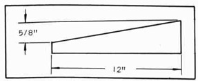
PURPOSE OF A DECLIVITY BOARD
Fig. 157-5/8" Declivity Board
In order to make launching a ship possible, the ship is built on
an incline with the bow higher
than the stern. When the ship
is ready for launching, it
slides down this prepared incline.
A declivity board is
used during the erection of
the ship when on the ways.
This means that throughout
the construction of the ship
allowance must be made for this slant in the ways. The declivity
board is the instrument that is used to compensate for this slant and
make possible the use of a level. See Fig. 157.
The declivity board is tapered exactly the same amount as the
slant of the ship while on the ways. It follows that all units which
are installed on board ship must be placed in such a position that
when the ship is launched, the units will ride level with the ship.
The declivity is usually marked on the ways. Declivity boards are
made in the carpenter shop and have a taper corresponding to the declivity marked on the ways. This is usually 5/8" per foot. Thus a
declivity board one foot long is 5/8" wider at one end: The narrow
end is 4" and the wide end is 4-5/8". Fig. 158 shows how a declivity
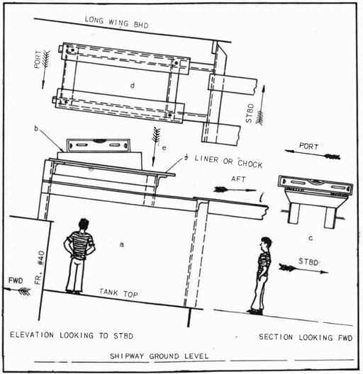
board is used to level an installation.
Take a good look at the illustrations on the next page. Fig. 158,
at "a" is what a person would see if he stood with his face toward the
job as shown by the figure of the little man. His left side is toward
the bow of the ship; his right side is toward the stern of the ship; and
he is facing toward the starboard side of the ship.
He is standing on a tank top that makes a floor, level with the
keel of the ship. On his left is another tank top which rises a little
higher than his shoulders. Above his head and in front of him is a
frame work which has been welded in position to hold a bilge pump. This
frame work is called a foundation. The foundation has to be level with
the keel of the ship as it rides in the water. When the ship is on the
120
ways, the bow is much higher than the stern, 5/8" for every foot in
length. If the ship is 500 feet long, the bow will be 26.04 feet higher
than the stern.
Figure 158 at "b" shows a declivity board resting on the top of the
foundation and a level resting on the edge of the declivity board. As
the declivity board is the same angle as the angle of the ship's keel
when on the ways, the top of the foundation will be level when the ship
is launched.
Fig. 158--Leveling a Foundation in a Ship on the Ways
Now, as our little man walks around to the right side of the frame
work and stands in the position shown he will see the platform top as
shown in Fig. 158 at "c". As the platform in this view reaches in a
port to starboard direction, and as the ship is resting level from port
121
to starboard on the ways, no declivity board is needed to make the
foundation level athwartship.
Figure 158 at "d" is the top of the platform or foundation, and
this is what the little man would see if he were standing right above
the foundation and looking down in the direction of the arrow, 158 at "e".
Foundations are usually leveled up by grinding any high spots after
the frame work has been welded in place correctly. But if some very particular job of installing a unit has to be done, the pump, or generator,
or whatever it is, may be set up and leveled by following the outline
given below.
GENERAL PROCEDURE
1. Locate the unit to be installed. See the blueprint.
2. Select a machined surface that may be used as a base on which
to rest the declivity board. Check with the leader when
choosing this surface.
3. Place small wedges or jacks for small units; use large wedges
or special jacks for heavy units.
4. The declivity board is placed with the wide end aft when
trying the work for level. See the illustration below.
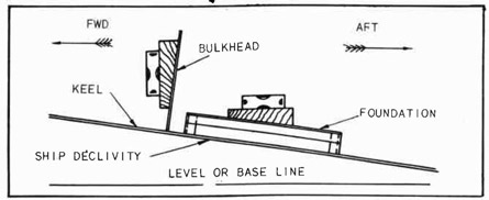
Fig. 159-Plumbing a Bulkhead in a Ship on the Ways
NOTE: When the machinist is plumbing bulkheads or other jobs
involving the upright use of the declivity board, he
must place the wide end of the board up and forward
if he is trying the work for plumb on the forward side;
he must place the wide end down and aft if he is trying
the work for plumb on the after side.
5. Try the work with the level. Use wedges, or adjust the jacks
to change the position of the unit being installed until the
job checks level and plumb all around. Check with the instructor.
NOTE: When making the work level from port to starboard no
declivity board is used. Use the level in the usual
manner, but see that it is lined up on a true surface such as a tank top, the top of the foundation, or
a generator flat.
122
QUESTIONS
1. What is meant by the "declivity" of a ship?
2. Explain the shape of a declivity board.
3. Where are declivity boards obtained?
4. How does one know the declivity of a certain shipway?
5. Why is a declivity board unnecessary when a unit is
leveled athwartship?
6. Which end of the declivity board is up when the after
side of a bulkhead is being plumbed while the ship is
resting on the ways.
Striking a Chalk Line
PURPOSE OF A CHALK LINE
When locating a deck stand, a deck winch, or other similar unit,
the location must be found from the CENTER LINE on the blueprint. The
center line of the ship should be marked with a center punch in the deck
plating. See line "l-l", Fig. 160. The center line of the unit location must be marked parallel to the ship center line. See line "b-b",
Fig. 160. A chalked line is held through these two points parallel to
the ship center line, drawn taut, and snapped down on the deck. A fine
chalk mark, parallel with the ship center line, will register on the
deck. This chalk line is then marked about every two inches with a
center punch. See Fig. 160, "l-l".
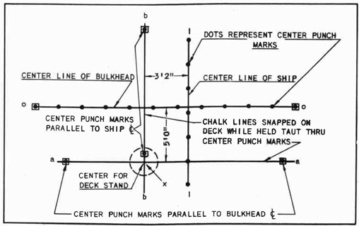
Fig. 160-Locating a Deck Stand Center from ship Center Lines
123
The center punch marks in the small squares shown on Fig. 160 are
located by measuring from the ship center line or from the bulkhead center line. The ship center line and the bulkhead center line are usually
center punch marked on the deck of the ship. In some instances this is
forgotten, and there is no center line from which to measure. When these
center lines have not been marked, they will have to be established at
once. All measurements must be taken from center lines.
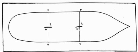
To establish a center line when there is none marked, proceed as
follows:
1. Examine the blueprint carefully, and find the dimension which
gives the distance from port to starboard from inside to inside
of the sheer strakes.
2. Using one half this distance, measure from the port or Starboard side, inside the sheer strake, from a point forward,
inboard. See Fig. 161 at "r". Take another measurement from
point "s" inboard. Mark the distance with soapstone at "t".
Fig. 161--Establishing a Center Line
3. Repeat step 2 from the opposite side at points "u-v" and mark
the distance as before at points "w-w".
4. With the center punch, make a punch mark:
(a) On the short lines if they come exactly in the same place.
(b) Between the short lines if they do not come exactly in
the same place.
5. With a cold chisel, make a square around the center punch marks
as on the "l-l" line, Fig. 160.
6. Examine the blueprint carefully, and select a welded joint between two deck plates parallel to the bulkhead that comes close
to the desired bulkhead center line.
7. Go below, and locate the distance from the weld to the bulkhead. Take this measurement at port and starboard.
8. Come up on deck, and lay this distance off from the welded
joint in the desired direction.
124
9. Mark these points with soapstone, and center punch the location
as in step 4. Box the center punch marks with cold chisel as
in step 5.
10. With the chalk line held taut through the center punch marks,
snap a line on the deck plate, as at "o-o", Fig. 160.
11. Make center punch marks all along both center lines as shown on
Fig. 160.
NOTE: When measuring distances, always measure at a right
angle from the starting point. Fig. 11 and 13, Part I.
LAYING OFF LOCATIONS
Having established ship and bulkhead center lines (or in case the
center lines were already marked off on the deck), lay off the location.
or locations of units, as outlined below.
TOOLS AND EQUIPMENT
1. Center punch
2. Machinists' hammer
3. 6' steel tape
4. Chalk line
MATERIALS
Chalk
Soapstone
Cold chisel
PROCEDURE
1. Find the center line of the ship on the deck, "l-l", Fig. 160.
2. Find the center line of the bulkhead, "o-o".
3. Measure off a distance of 5'-0" at a right angle from "o-o"
to "a-a" and mark with center punch as shown. Have center
punch marks as far apart as possible for greater accuracy.
4. With the chalk line held taut through the center punch marks,
"snap" the line on deck, leaving a chalk line.
5. Measure off a distance of 3'-2" at a right angle from "1-1"
to "b-b" and mark with center punch as in step No. 3.
6. With the chalk line held taut as before, snap a line through
these center punch marks.
7. At "x", where the two lines "a-a" and "b-b" cross, is the center
of the deck stand location as shown by the broken circle.
NOTE: There may be several deck stands centered on the same
center line, about two feet apart. In this case, one
center line will serve in one direction. Intersecting
or cross lines for centers are measured off at right
angles from the main center lines "l-l" or "o-o".
Be sure to center punch the location of a chalk
line as soon as it is made. Unless this is done, the
line may be blurred by footsteps or by objects dragged
across it.
QUESTIONS
1. State the reason for holding a chalk line taut when striking a line.
125
2. What should be done immediately after a chalk line is
struck on a surface?
3. Explain how the location of a chalk line is marked on a
surface.
4. Point out the advantage of having center punch marks as
far apart as possible when preparing to strike a chalk
line.
5. At what point is the center of a circle found when chalk
lines are used?
6. Explain how the center line of a bulkhead is located if it
has not been marked with the center punch on the deck.
7. Why does the mechanic mark a box with a cold chisel around
center punch marks?
8. When the distance athwartship measures 69'-11", what distance is measured to the center to find the ship center
line?
9. If this distance varies slightly, fore and aft, how will
the job of finding the ship center line be affected?
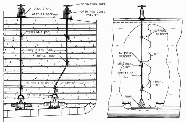
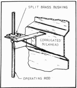
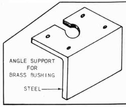
Setting and Fitting a Deck Stand
PURPOSE OF A DECK STAND
Deep in the hull of a tanker, valves are installed which control
the flow of the cargo from tank to tank or from tank to discharge outlet. There may be valves, too, to control steam outlets.
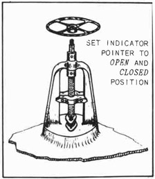
Fig. 162-Deck Stand Assembly
These valves are operated from
the weather deck. The blueprint
showing the general arrangement of
the weather deck will show the locations for the upper end of the operating rods which control the valves
below decks. These operating rods
are usually 1-1/4 inch diameter
shafting, hang from a support on the
weather deck, and extend down to the
valves. See "Installing Operating
Rods" for the arrangement or the location of operating rods.
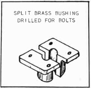
The support on the weather deck
for the upper end of the operating
rod is known as a "deck stand". See
Fig. 162.
GENERAL INFORMATION
Deck stands may be located on
the weather deck, fore, aft, port, and starboard. While the deck
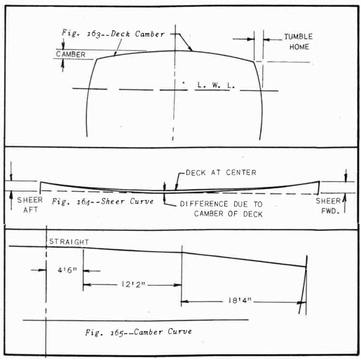
appears to be level, it really is a curve, composed of straight lines.
See Figs. 163, 164, 165. (Camber, sheer curve, camber curve.)
126
Curves That Must be Considered When Setting Deck Stands
A glance at the illustration of a deck stand will show that the
base or bottom of the stand is straight and at right angles with the center line. Each stand must be leveled with the vertical center line of
the ship and machined off to fit the deck at the desired location.
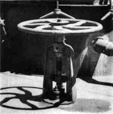
Figure 167 shows two deck stands installed on the weather deck of
a ship. The deck stand at the left has been installed correctly, that
is, vertical, athwartship. The center line of the deck stand, and of
course the operating rod, will be parallel with the vertical center line
of the ship.
The deck stand at the right shows what would happen if the stand
had been set with the weather deck.
The operating rod would be cramped, especially if this rod is to
hang straight down with no universal joints required. There would also
127
be a lot of trouble caused when the support brackets were being installed.
Deck stands must be fitted and set level.
Fig. 266--Deck Stand Installed
The Hand-Operated Wheel Has a
Square Hole Which Fits Over the
Square End of the Operating Stem,
A Nut is Placed on the Threaded
Part of the Squared End and Drawn
Down Tightly to Hold the Hand Wheel
Securely in Place.
Fig. 167--Correct and Incorrect Deck Stand Setting
TOOLS AND EQUIPMENT
1. Portable air drill
2. Chalk line
3. Fifty-foot steel tape
4. Center punch
5. Machinists' hammer
6. 10" dividers
7. Open end or adjustable wrench - 1/4" to 1" U.S.S.
8. Level
9. Declivity board
MATERIALS
Marking paint
Soapstone pencil
Blue or white chalk
GENERAL PROCEDURE
1. Lay out location for deck stand from blueprint.
2. Place deck stand, and line up with level. (Use Declivity
Board.)
3. Lay off base line on bottom of stand, level with ship declivity.
4. Mark location of deck stand on the deck with marking paint.
5. Take deck stand to machine shop and have it machined to base
line.
6. Set it on a previously prepared location and have welded fast.
128
7. Install the indicator slide and pack the stuffing box after
the operating rods are installed and inspected.
QUESTIONS
1. Explain the purpose of a deck stand.
2. State how the bottom of a deck stand is correctly prepared
to insure that the vertical center line of the stern will
be parallel with the vertical center line of the ship.
3. How is the deck stand fastened to the weather deck of the
ship?
4. Why are deck stands located and installed before operating
rods are fitted?
5. Why are brass sterns used in deck stands?
6. Give the reason for using a stuffing box on a deck stand.
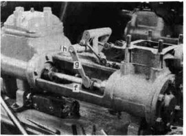
Installing a Pump
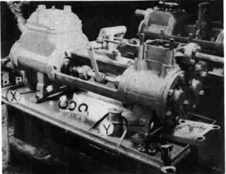
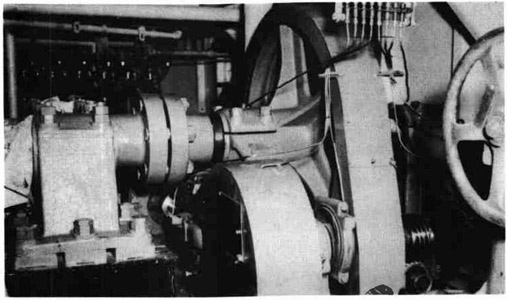
Fig. 168--Horizontal Steam Pump on the Foundation
Figure 168 shows a
horizontal, duplex steam
pump. The rigid base of
the pump-body casting is
supported on the foundation by two feet, "X" and
"Y". The unit is lowered
to place by the ship
riggers under the supervision of the outside
machinists. The blueprint gives the correct
location for the pump
and the number of bolts
required to secure the
unit to the foundation.
The thickness of the
chocks is determined by
the distance between the
foundation top and the
underside of the supports "X" and "Y", which is usually one inch.
The instructions given herewith are understood to be general procedure. Larger units and different types of pumps may require the
employment of installation methods not mentioned here. Circumstances
will govern the procedure.
TOOLS AND EQUIPMENT
1. Center punch
2. Scale
3. Hammer
4. Dividers
5. Chalk line
The work of installing a pump may be outlined as noted below:
PROCEDURE
1. Check the foundation with a straight edge to make sure it is
level.
2. Grind off any high spots where chocks are to be fitted.
3. Place the pump in correct location given on the blueprint.
4. Place wedges under the foot support in a way which will not
interfere with measuring between the foot and the foundation
for chock sizes; and raise the pump to the correct height,
which is shown on the blueprint.
5. Use inside calipers, and adjust the pump to the height shown on
the blueprint.
6. Get chock sheets and write down the sizes for the chocks all
around. Mark the chocks and the pump base for the chock
locations.
7. Send the chocks to the machine shop to have them machined to
the correct size.
8. Fit the chocks at the correct locations as instructed in Part
II, Fig. 127.
9. Have the leader check the chocks.
10. If approved by the leader, drill the corner holes according to
instructions.
NOTE: The hole in the base may be used as a guide to drill
the foundation. Sometimes the chock is drilled with
the foundation; and at other times the position of the
hole in the chock is scribed through the hole in the
foundation, and it is centered and drilled in the shop.
Circumstances govern the procedure.
11. Drill through the unit base, the chock, and the foundation with
a drill of a size that will leave 1/16" in the diameter of the
hole for reaming.
12. Ream to the size given on the blueprint.
13. Call for four fitted bolts from the machine shop, metal to
metal fit. Give the diameter of the reamed hole.
14. Install the fitted bolts, and pull them down tight.
15. Drill the other holes in the base of the pump through the
chock and foundation according to the size given on the blueprint.
16. Install black bolts in these holes, and pull them down tight.
17. Have the leader inspect the job and give his approval.
130
QUESTIONS
1. Why are the high spots ground off of the foundation where
the chock is to be fitted?
2. Where do we find the location of the pump on the foundation?
3. Explain how wedges should be placed under the feet of the
unit to prevent interference with measuring for chock
thickness.
4. What is meant by a "metal to metal fit" when referring to
fitted bolts?
5. How much is allowed for reaming in the drilled diameter of
a hole?
6. Explain the procedure for drilling chocks.
7. State how the size of fitted bolts should be given to the
shop when the size of the reamed hole is 1-1/2 inches.
Lining Up Pumps and Motors
IMPORTANCE OF ALIGNMENT
Pumps, motors, turbine generators, reduction gears, and excitors
are all found in different, combinations aboard ship. These units are
very costly, and a little carelessness in alignment may ruin bearings or
shafting because one unit of the group is not "in line" with another
unit of the same group. See Fig. 169.
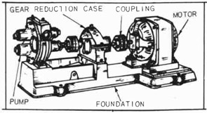
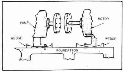
Fig. 169--Reduction Gear Driven Pump Setting
The illustration shows
the motor set on a part of the
foundation which is lower than
the level on which the reduction gear and pump are located. Instead of the foundation shown, a welded steel
foundation is often used.
The welded steel foundation is
not always absolutely level,
although it may be fairly
flat.
After the foundation is
ground off as nearly perfect
as possible, there is still a chance that it may be slightly uneven.
This is the reason that chocks have to be used to level up the units, to
bring the center of the driving shafts in line so that they will turn
freely in the bearings. A tight bearing causes friction and quickly
overheats, resulting in a "seized" shaft or a "burnt out" bearing. Serious trouble at a critical moment can result from faulty alignment of
units.
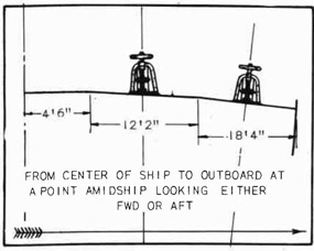
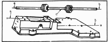
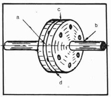
Figure 170 shows the coupled shaft which is used in the pump and
motor unit shown in Fig. 169. Points "a" and "b" must be in a horizontal plane which is parallel to the horizontal plane of the unit foundation.
131
The shaft "c", which is coupled between the two outer shafts, must
line up with the center line of these shafts so that the continuous center line will assume a position exactly the same as if there were but
one piece of shafting extending from end to end of the entire unit.
Fig. 170--Alignment of Motor Shaft with Base
The center line of the shaft, which is at right angles to the horizontal center line, must also line up with the center line of the foundation "x-x". In other words, the shaft must be lined up straight and
true when viewed from any angle.
As the business of building and equipping the ship progresses, many
strains on the plates, bulkheads, and foundation supports are set up.
Heavy machinery is installed from time to time which adds weight to the
hull and causes some distortion of the entire structure. This distortion is noticeable in previously lined up motors and pumps; it is more
noticeable on larger and very heavy equipment.
It is necessary to go over the work and check the alignment several
times before it may be finally approved by the inspectors. Small pieces
of equipment do not require this repeated checking.
In addition to distortion caused by added weight, there is the
problem of temperature to be considered. Ships are built in cold
weather as well as in hot weather. The temperature varies during each
day to a greater or lesser extent, and this variation is reflected in
the length and diameter of shafting.
Consequently when an installation is lined up and checked and found
to be perfect, it does not mean it will stay that way. This statement
applies particularly to the line shaft from propulsion motor to propeller. If the job is checked at noon one day, it should be checked at
noon every day. Always check at the same time of the day.
When bearings are tightened up and couplings are bolted tightly
together, there is always danger that heat, generated by friction, may
swell the material and cause "hot spots". This is one of the reasons
that all such alignments of units installed must be checked over repeatedly until the ship is finally launched. This precaution applies
to large, heavy motors.
After the launching, the whole job must be checked again; for when
the ship takes the water, new strains and stresses are set up which may
possibly exert a pull on some critical piece of equipment and cause expensive damage to bearings, shafting, and coupling.
132
Some jobs have flexible couplings at the point where the shafts
are connected. These flexible couplings are designed to take up or
compensate for some slight out-of-line condition between a motor and a
pump, between a steam turbine and a reduction gear, or between a reduction gear and a motor.
However, if the-out-of-line condition is too great, an overstrain
which will cause excessive wear will be put on the flexible coupling
mechanism. When this happens, the flexible coupling will not work smoothly, jerks and knocks will develop, and finally the unit will have to be
overhauled and repaired to avoid a complete breakdown. It is impossible
to use too much care in lining up any of these units.
After the fitter gets the pipes connected to a pump or to a steam
turbine, these units should not be moved for lining up the drive shaft.
There are two reasons for this. First, it is very difficult, if not
impossible, to move one of these units after the pipes are connected.
Second, even if the unit could be moved or if the attempt was Made,
some of the pipe joints could be damaged and cause expensive leaks.
Such damage would mean serious trouble, perhaps at a very critical moment.
Set the pump, or steam turbine, first; then have the piping connected. Always line the motor up with the pump, or with the steam turbine.
There are no pipes to hinder the aligning.
The electric cable connections are flexible and may be moulded
without hindrance to the aligning job. Ask the instructor to explain
this particular point for a thorough understanding of the operation.
Aligning a Coupling
INFORMATION
Pumps, motors, turbines, and exciters are coupled with each other
in combinations of pump and motor; turbine, motor, and exciter; exciter
Fig. 171--Line Shaft Connected with Couplings
133
and motor; etc. Each unit must be lined up so that the main shaft
(axle) will run exactly in line with the main shaft of the unit with
which it is connected. This connection is called a coupling. The ends
of two shafts, with the coupling on each shaft end are shown in Fig.
171. This particular job is the line shaft coupling at the forward end
of a steam steering mechanism.
Notice the wedges under the bases of the pump and the motor. Fig.
171-A. These wedges are placed all around the units to be installed in
such a way that there is no interference with the operation of fitting
the chocks after the entire unit has been leveled on the foundation. If
the foundation is level, the operation of setting up the installation may
proceed at once. If there are rough spots, bumps, or uneven places on
the foundation, they must be leveled off with the portable grinder.
Check very carefully with a straight edge and a level.
Fig. 171-A--Leveling an Installation with Wedges
When installing turbine generator sets, pump and motor sets, etc.,
never attempt to shift the pump or the turbine to align the coupling
after the pipe fitter has done his job of connecting the necessary piping. Always make any adjustments necessary by shifting the motor.
On many large installations, such as turbine generator reduction
gear jobs, the manufacturer of the equipment sends a man along to supervise the work. Do not attempt to set the pump or motor until the foundation is level.
Sometimes, instead of wedges, it is possible to use several pieces
of steel about one inch thick placed under the bases of the units to be
installed. Jacking screws are sometimes used to level the unit. When
the motor or pump, or both, have to be shifted sidewise in order to
align the couplings, side jack brackets are welded in convenient spots
on the foundation, and large set screws are used to shift the unit sidewise or endwise.
Thin shims may be used under the steel packing blocks to bring the
couplings into proper alignment. It should be clearly understood that
the aligning of couplings begins at the time the measurements are being
taken for the chock sheet.
134
When the chocks are fitted and the units are finally bolted down
securely, the couplings must be in perfect alignment. Shims are not
used. Each chock must be well fitted so that the bolting-down process
will not pull the couplings out of line.
1. Check the foundation with level and straight edge. (Grind off
any uneven spots with portable grinder.)
2. Set unit on blocks or wedges, and level with foundation at the
location specified on the foundation drawing.
3. Have side jacks welded to foundation to provide means for adjusting the unit sidewise or endwise.
4. Break the coupling (remove the bolts from the coupling flanges)
between the units being installed in order to check the alignment of the coupling flanges.
5. Adjust wedges (or other packing that is used) until the outside
diameters and faces of the coupling flanges run true when revolved by hand.
METHOD OF CHECKING ALIGNMENT
USING A 6" SCALE
Check the distance between the faces of the coupling flanges at 90
degree intervals; that is, find the distances between faces at points
"a" (Fig. 172), "b" (on the opposite side), "c", and "d" (opposite "c").
Fig. 172-Aligning Coupling Faces
This will show whether or not the
coupling faces are parallel with each
other. If not parallel, adjust the motor
or pump, using shims, until the couplings check true. The instructor will
demonstrate the checking of these distances.
At the same time that step "a" is
going forward, the outside diameters of
the coupling flanges must be kept in
line. Use the scale, placed across the
two flanges as shown in Fig. 173.
If the flanges do not line up, it
will be necessary to raise or lower one
of the units and perhaps shift it sidewise by means of the jacks which were welded on the Foundation.
135
Fig. 173--Aligning Flange Diameters
The scale should be tried at intervals
of 90 degrees as was done when checking
between the faces of the flanges.
METHOD OF CHECKING ALIGNMENT
USING THE THICKNESS GAUGE
When the thickness gauge is used, the
procedure is much the same as when using
the scale. When the outside diameters of
the coupling flanges are not the same, use
the scale on the surface of the larger
flange and try the "feelers" between the
surface of the smaller flange and the edge
of the scale.
Fig. 174-Checking Faces with "Feelers"
The distance between the coupling
flanges may be checked with the thickness gauge when the space is very narrow. See Fig. 174. Wider spaces are
checked by using a piece of square
key-stock and the thickness gauge.
The couplings may be revolved,
one at a time, and checked in several positions to find if the faces
are true with the shaft. This is
usually done at 90-degree intervals.
If the faces are not true, the reason
is that the shaft has been sprung.
In this case check with the instructor or leader. Many times the shafts
have to be taken out and sent to the
machine shop to be re-worked.
METHOD OF CHECKING ALIGNMENT
USING AN INDICATOR
When the dial indicator is used, clamp the indicator to one coupling flange and revolve the opposite coupling. If the indicator shows
no variation, the coupling is running true.
Revolving the coupling with the indicator clamped fast while the
opposite coupling stands still will show how much the coupling centers
are out of line. Then an adjustment is made, and the job is checked
again.
NOTE: A dial indicator should be used wherever possible when
aligning a coupling. It is well to attach an indicator and
check the alignment of some units before installing. Cargo
pumps are always installed after checking with the indicator.
6. After the chocks are fitted, call the inspector for chock and
alignment inspection.
7. If the inspector gives his approval, pull the bolts down tight.
8. The job is again inspected thoroughly. If the second inspection
shows the job to be satisfactory, dowels are fitted through the
136
unit bases to prevent any chance of the shafts' getting out of
alignment. Check with the leader at this point.
9. After the dowel Job is completed, install and tighten the coupling bolts securely.
GENERAL PRACTICE
The foregoing procedure is general practice. Different types of
installations call for special methods of handling. For each particular
job, arrangements are made to take care of unusual situations. The final
check on motors, pumps, and turbo-generators is made after all piping
is completed, no matter what the installation may be.
Check with the leader at every move. Be extremely careful to make
perfect fits. The mechanic must have a lot of patience as well as skill,
and he must be an honest workman.
QUESTIONS
1. What Is the objection to setting a motor and aligning a
pump with the motor?
2. Explain how this job of aligning a pump and motor should
be done.
3. What causes a pump and motor unit to show misalignment
after all the foundation bolts have been pulled down
tightly?
4. Name some of the causes of an installation's aligning satisfactorily one day but being found badly out of line two
or three days later.
5. Explain why several inspections may be necessary before
the installation can be approved.
6. State the purpose of flexible couplings between driving
shafts.
7. Explain what happens to a flexible coupling if the installation is badly aligned.
Overhauling a Pump
DESCRIPTION OF A HORIZONTAL,
DUPLEX, STEAM-DRIVEN PUMP
The illustration, Fig. 175 shows a horizontal, steam-driven, duplex
pump. This type of pump is commonly used for pumping bilge water and
may be used in some cases for pumping cargo (oil). The size of the pump
is usually stamped clearly on a name plate affixed to the pump. For example: 6" x 4" x 6". The first Figure (6) is the diameter of the cylinder on the steam end; the second Figure (4) is the diameter of the liquid cylinder; and the third Figure (6) is the length of the stroke.
In viewing a horizontal pump from the steam end, the cylinder to
the right is the right-hand cylinder; the cylinder to the left is the
left-hand cylinder. Complete details are shown in cross section, Figs.
187 and 188.
137
Fig. 175--Horizontal Duplex Steam Pump in operation
A single-cylinder, horizontal pump is listed as a Horizontal Simplex; a single-cylinder, vertical pump is listed as a Vertical Simplex;
the twin-cylinder vertical is listed as a Vertical Duplex. As the name
"Duplex" implies, the cylinders are twins; there are two cylinders side
by side at each end. The driving end where the steam enters is called
the "steam-end". See Fig. 175 at "a". The pumping end, through which
oil or water is pumped, is called the "liquid-end". See Fig. 175 at
"b".
The steam enters the steam chest through inlet 1, Fig. 176, placing
the chest under pressure. The steam passes into the cylinder by way of
inlet port 39, Fig. 176, forcing the piston forward. At the same time,
the piston in the adjoining cylinder is moving in the opposite direction.
This alternate action produces a constant flow in the liquid-end of the
pump.
The valve in the steam chest, Fig. 176 at "3", is termed a flat-faced, D-type slide valve and is called a direct action valve because it
is connected by links to the opposite piston rod. It will be noticed
that the D-valve has no springs or other mechanical devices to maintain
the seal with the mating port faces. This seal is insured by the pressure of the steam in the chest acting on the back of the valve area,
pressing it tightly to the seat. For example; the pressure the time at
the ports open would be 100 lbs. The area of the valve backs is 7
square inches. Then the force tending to hold the valve to the seat
would be 7 x 100, or 700 lbs., plus the weight of the valve. It should
be clear that no mechanical pressure is necessary to seal the valve.
As each steam piston makes a stroke, the plunger on the liquid-end
is forced ahead or back because the steam piston and the liquid-plunger
are mounted on opposite ends of the same rod. See Fig. 176 (Cross
Section).
NOMENCLATURE OF PARTS
HORIZONTAL, DUPLEX STEAM PUMP
1. Inlet to Steam Chest
2. Valve Nut or Tappet
3. "D" Type Slide Valve
4. Valve Rod Stuffing Box
5. Valve Rod Stuffing Box Gland
6. Valve Rod
7. Valve Rod Knuckle End
8. Valve Rod Knuckle Pin
9. Valve Rod Connecting Link
10. Cross Shaft
*11. Lever (See Note)
*12. Crank (See Note)
13. Cross Shaft Stand or Pedestal
14. Cradle
15. Liquid Piston Rod Stuffing Box Gland
16. Liquid End Stuffing Box
17. Liquid End Cylinder Casting
18. Discharge Valve Plate or Diaphragm
19. Discharge Cap or Head
20. Discharge Valve Spring Guard
21. Discharge Valve Spring
22. Discharge Valve Disc
23. Discharge Valve Seat
24. Suction Valve Spring
25. Suction Valve Disc
26. Discharge Outlet
27. Suction Valve Seat
28. Liquid Cylinder With Pressed-in Liner of Bronze
29. Liquid Cylinder Head Cover
30. Suction Inlet
31. Piston Follower Nut
32. Piston Follower
33. Piston Body
34. Liquid Piston Rings (Hydraulic Duck-Metallic or Rock-Hard Fibrous) Depending on service
35. Piston Rod
36. Piston Rod Spool or (Threaded, Split-Type Crosshead)
37. Steam Piston Rod Stuffing Box Gland
38. Steam Piston Rod Stuffing Box
39. Steam Inlet Ports
40. Exhaust Ports
41. Steam Cylinder Piston With Cast Iron Rings
42. Steam Cylinder Head
43. Supporting Bases
*NOTE: Levers and Cranks
A long lever on right side connects
to long crank on left side to left
steam cylinder valve.
A short lever on left side connects
to short crank on right steam cylinder valve.
139
PISTON ROD MOTION
Fig. 177-Adjusting Valve Slide Rods
The motion of the
piston rod is controlled
by the slide valves in
the steam chest. See Fig.
177 At "c-c". The slide
valves are so adjusted
that the steam is admitted to one end of the
cylinder to force the
piston in one direction.
See Fig. 178. The slots
in the cylinder body at
the base of the steam
chest are the steam ports.
Slots "a-a" are inlet ports,
one on each end of the cylinder which makes it double-acting. Slots "b-b" are exhaust ports. Slot
"f" is the main exhaust port, cored through the casting to exhaust discharge connection. The mechanic is holding a slide valve in each hand
at "d" and "e" in Fig. 178.
VALVE TAPPET
Fig. 178-Checking Valve Slide for Fit
The valve nut or tappet, Fig. 176 at "2", is placed between the two
IT-shaped lugs shown on the back of
the slide valve in Fig. 178 at "d".
The tappet is narrower in width
than the space between these lugs,
giving a designed lost motion, usually 1/2", the width of the inlet port on each side of the nut.
When the valve is set in central
position or dead center as in Fig.
176, it is in position for adjustment. This condition can never
occur in actual operation because
every port (inlet) is closed.
This lost motion designed in
slide valves is provided to eliminate a positive "dwell" on both
cylinders simultaneously, which
would give a pulsating action to the water discharge. The lost motion
keeps one piston in motion at all times, eliminating the undesirable
surge which would be caused by the overlapping action.
As this sequence of motion continues, the plunger in the liquid-end
of the pump forces the water or oil to move in a continuous flow. This
continuous flow is possible because one plunger is going ahead when the
plunger beside it is backing up. One plunger sucks the liquid into the
chamber, and the other plunger pushes the liquid that was sucked in on
the previous stroke out of the chamber. Figure 179 shows the liquid-end
of the pump with the bonnet removed. The mechanic is holding the discharge valve plate. One valve stem, valve, and spring assembly have
been removed.
140
PISTON ROD SPOOL
Fig. 179--Liquid End of Pump with Bonnet Removed
The piston rod carries
3. spool, Fig. 176 at "36"
and Fig. 180 at "f", located in a central position
between the steam and
liquid ends. The spool is
fastened by a tapered, fitted pin and a set screw; and
it is cut out to form a U-shaped opening which actuates
the valve-operating lever
and also prevents the piston
rod from revolving. This
revolving action will occur
if the piston rings bind in
the steam-piston grooves.
(The action of the steam on the diagonal-cut gaps of the piston rings is
similar to a screw or twisting thrust as in a Mitchell-Thrust slipper-action.)
Fig. 180--Horizontal Pump Valve Mechanism
CYLINDRICAL SPOOL
Some pump manufacturers
use a cylindrical spool without
a milled flat as in Fig. 180 at
"f", and to prevent the piston
rod's turning they employ a slotted extension on the spool which
engages a rib extension. The
rib extension is cast integral
with the cradle casting, directly under the piston-rod spool.
VALVE OPERATING LEVERS
The upper end of the valve
operating lever (11, Fig. 176)
is keyed to a cross-shaft (10,
Fig. 176). The cross-shaft
operates in bronze bushings in the cross-shaft stand (13, Fig. 176).
The other end of the shaft carries the crank (12, Fig. 176) which is connected by a pin through the drilled end of the valve rod connecting link
(9, Fig. 176). The other end of this link is connected to the forked
end of the valve rod called the valve rod knuckle end (7, Fig. 176)
by a knuckle pin (8, Fig. 176). The tappet (2, Fig. 176) is adjustable
on the threaded valve rod (6, Fig. 176) to permit adjustment of slide
valves by disengaging knuckle pin and turning the valve rod in or out,
as required.
SLIDE VALVES
The two valve slides are shown at 1 and m, Fig. 182. Notice 1 slide
is forward while the adjoining slide is to the rear. Two steam ports may
be seen at opposite ends of the steam chest. Figure 185, "n" and "o",
141
Fig. 181 Vertical Simplex Pump
shows the mechanic making a final check of
the valve setting. Note that the pin may be
withdrawn and the link dropped out of the
forked end so the valve stem or spindle may
be screwed in or out of the valve slide nut
to adjust the valve timing.
All of these parts of the pump-operating
mechanism must be adjusted correctly and kept
in good working order or the pump will fail
to function efficiently.
VERTICAL SIMPLEX
Figure 181 shows a Vertical Simplex pump.
The working mechanism is much the same as in
the horizontal pump. Both types of pumps
are used for similar purposes. The construction of the pump in Fig. 181 does not employ
a cast cradle, but has three tie rods between
the steam and liquid ends. When erecting
this type of pump, the mechanic must exercise
extra care in the alignment of the cylinder.
The best practice is to align the cylinder
with a tight wire, with heads and reciprocating assembly removed to facilitate a thorough check.
PUMP LIQUID-END
Figure 186 is a view of the liquid-end of a vertical pump. The
mechanic is fitting a ring of packing material around the piston rod.
The gland is directly above and will be used to push the packing ring
into the stuffing box to make room for the next ring which is shown lying
on the liquid-end valve chest. Figure 181 shows eight large nuts and
plugs which are binding bolt, pin, nuts, and lock nuts for suction and
discharge valves. These are eight each in number in a monochest construction. See Fig. 184.
Fig. 182--Horizontal Pump with Steam
Chest Cover Removed
VALVE LEVER CROSSHEAD
Figure 181 at "a" shows
the valve lever crosshead
(split type) which joins the
two piston rods. Four bolts
and four castellated nuts are
used to clamp the crosshead to
the piston rods. The bolts
are drilled for copper wire
which is used as a locking
device as shown. Fig. 181 at
"b" shows a hole used to
connect the valve-operating
lever to the auxiliary valve
rod by means of connecting
link and pins.
142
OVERHAULING JOBS
Overhauling jobs on a horizontal, duplex pump consist of opening
the pump steam cylinder and renewing the piston rings; grinding and reseating the valve slides; adjusting the valves; renewing or reboring the
lining in the liquid-end of the pump; replacing badly worn piston rods;
etc.
As the greater part of this instruction must be given on the job
under the supervision of an experienced man, it is considered sufficient
for instructional purposes to concentrate on some one overhaul job. The
description of a pump already given in the text and the procedure for
one example of a pump job should enable the trainee to go ahead with general pump overhauling under minimum supervision.
A typical example of a pump-overhauling job is the work of opening
the pump steam cylinder and renewing the piston rings.
PISTON-RING WEAR
Figure 183 shows a piston rod and plunger details. The piston
rings must be renewed and new packing must be installed in the stuffing
boxes. The plunger rings may have to be renewed. If there is excessive wear on the piston rod, a new rod is installed. Figure 175 shows a
piston rod in place with the stuffing box nuts tightened snugly.
Fig. 183--Piston Rod and Details
Fig. A NOMENCLATURE
Steam End
a- Castellated Nut (Steam Piston Lock Nut)
b- Steam Piston with Rings in Grooves
c- One piece Bronze Piston Rod
d- Metallic Packing- Cut Rings (steam end)
e- Stuffing Box Gland
f- Stuffing Box Gland Nut (Serrated type; Use Spanner Wrench)
The steam piston in a pump has two or more cast-iron rings. When
these rings wear or lose their tension, the steam will pass by them.
This reduces the power and efficiency of the pump. It is then necessary to renew the rings. There are several reasons why piston rings
wear. Lack of lubrication is the principal reason. A sloppy ring fit
when the pump was first put into operation is a contributing factor.
Whatever the reason for the wear, it is essential that all the defects
be eliminated when the pump is overhauled.
OVERHAULING A PUMP
When overhauling a pump of any description, always mark the location of parts that are to be removed, to facilitate the re-assembling of
the unit. Wire all bolts, nuts, and other parts together, and wire the
parts to some part of the unit to prevent their being lost.
Fig. 184--Monochest Valve Assembly
Nomenclature of Water-End Valve-Assembly of a Vertical Simplex,
Steam-Driven Pump (as shown in
Fig. 184, "Overhauling a Pump".
NOTE: This type of Valve-assembly
is termed Monochest construction.
1. Lock nut
2. Binding-Bolt Nut
3. Lead Ring
4. Liquid-End Housing
5. Valve-Guard Binding Bolt
6. Access Hole
7. Discharge Valve
8. Valve Seat (Pressed-in Taper or Threaded)
9. Suction-Valve Guard
10. Valve Spring
11. Valve Guide and Binding Pin
12. Suction Valve
13. Suction-Valve Seat
14. Valve Cover Plate and Gasket on this surface.
15. Valve Spring
16. Discharge-Valve Guard
TOOLS AND EQUIPMENT
1. Rammer
2. End wrenches
3. Dividers
4. Center punch
5. Packing hook
MATERIALS
Used Pump
Cast-iron piston rings
The work of the opening up a pump steam-cylinder and renewing the
piston rings may be outlined as follows:
144
PROCEDURE
1. Make sure the valve and the exhaust valve are closed before
beginning the overhaul job.
Fig. 185--Checking Valve Slide for Position
2. Open drain valves on
bottom cylinder to
release steam pressure.
3. Remove nuts from cylinder head with end
wrench and hammer.
4. Mark (with punch)
cylinder head position in relation to
the cylinder. This
is done in order to
place the head correctly when re-assembling. Remove
head from cylinder.
5. Remove nuts from packing gland. Remove gland packing from the
stuffing box.
6. Tram crosshead and rod with dividers. Register this setting on
some convenient part of the pump foundation so that the setting
may be proved when re-assembling the pump. Mark tram points
with center punch.
7. Remove tapered pin or lock screw from crosshead.
8. Screw rod from crosshead and remove rod and piston from cylinder.
Fig. 186--Pressing Packing into Place
9. Check cylinder, for oval shape and
taper, with inside micrometer. If
necessary re-bore the cylinder.
10. Take piston to machine shop for truing up ring grooves in lathe.
11. Have new rings made to fit ring
grooves and cylinder diameter.
12. Cut new rings with hack saw on 45°
bevel.
13. Rings are to be fitted to smallest
place in cylinder. Clearance on
beveled edges of ring should be
between .002" and .003" for each
one inch of cylinder diameter.
14. Fit rings to piston. Place piston
in cylinder, and screw rod in cross-head to tram marks. Replace lock
in crosshead.
145
15. Replace cylinder head with new gasket. Replace nuts on studs,
and tighten with wrench securely.
16. Repack rod stuffing-box with steam packing. Replace gland and
nuts. Tighten nuts on gland hand-tight with wrench.
STEAM END AND LIQUID END
The exhaust outlet is larger than the steam inlet. The exhaust
outlet is made larger than the steam inlet to prevent any back pressure
when the pump is running. The liquid-end inlet or suction opening is
larger than the discharge opening. Because of this difference in the
size of the inlet and discharge the pump plunger has a surplus source
of supply, and consequently a vacuum is avoided in the discharge line.
Fig. 187--Cross Section of Steam End of a
Horizontal Duplex, Steam--Driven Pump
146
Fig. 188--Cross Section of Liquid End of a
Horizontal Duplex, Steam Driven Pump
QUESTIONS
1. Why is it necessary to check the cylinder with the micrometer?
2. State how to determine the steam end of a pump from the liquid
end of a pump.
3. Why do rings have to be fitted to the smallest place-in the
cylinder?
4. How firmly are the packing-gland nuts tightened?
5. Why are tram marks registered on the pump foundation?
6. What is the reason for regrooving the steam piston in the machine shop?
7. What is the first thing a mechanic should do when about to
overhaul a steam pump?
147
Spotting and Scraping Bearings
GENERAL INFORMATION
A discussion pertaining to spotting and scraping bearings could be
extended to cover many types and sizes of bearings. It is not thought
necessary to make an exhaustive study of all types of bearings, but enough
space will be given to outline the general shipyard practice followed
when spotting and scraping the connecting rod bearings and journal crank
pins which are commonly used in the Sun Doxford main propulsion Diesel
engine.
WORKING PARTS INVOLVED
There are several main rods used in these engines. Two opposed
pistons are installed in each cylinder. The explosion of the fuel
forces the pistons apart. The pistons act on the main connecting rods.
The crankshaft ends of the connecting rods are fitted to the crankshaft journal (crankpin) and secured with a heavy cap. The connecting rod is spoken of as having an upper end and a lower end. See Fig.
190.
Fig. 189--Journal at Bottom Dead Center
WEIGHTS OF THE PARTS
The crankshaft weighs about
120 tons. Each piston weighs
about 5 tons. Each of the side
connecting rods weighs about 3 1/2
tons. The center connecting rods
weigh 5 tons each. When the mechanic fits automobile motor connecting rods to the crankshaft
bearings, he can hold the rod in
his hand, and he can lift and carry the crankshaft about in his two
hands; but to handle the diesel motor connecting rods, the machinist
must use chain falls or crane.
Fig. 190--Connecting Rod Assembly
148
THE WORKMAN'S RESPONSIBILITY
The work involved on this job is of an advanced nature. workmen are selected for their job because they have proved their mechanical ability on previous jobs. It is, then, the duty of each workman to consider each move carefully; to take no chances which could result in injury to himself or to others; and to work accurately and conscientiously. The final functioning of a diesel engine reflects the mechanical ability and the integrity of the workmen who assembled and fitted the several parts.
TOOLS AND EQUIPMENT
1. Spoon scraper
2. Flat scraper
3. 6" Thickness gauge
4. 12-point box wrench to fit
lower end nuts
5. Center punch
6. Machinist's hammer
7. Pin snips
8. 3' Pinch bar
9. 1" mikes
10. 20-lb. maul (sledge)
11. 2 1-ton chain falls
12. 1 3-ton chain fall
13. Electric drop extension cord (30) or longer)
14. End scraper
MATERIALS
Prussian blue
Lead wire, .018" in diameter
Shim stock, .002, 005, .010.
Cleaning fluid
Clean rags
Cup grease
Lead cards
PROCEDURE:
1. Turn the crankshaft so that the crank journal to be fitted is on the bottom, dead center. See Figs. 189 and 190.
2. Have the riggers lift the rod from the crankshaft.
3. Clean the crank journal, and stone any rough spots that may be evident.
Fig. 191--Chain Fall Holding Connecting Rod
in Place for Scraping
4. Clean the top half of the rod bearing.
5. Blue the crankshaft with a light film of Prussian blue. Apply it evenly and smoothly with the fingers.
149
6. Lower the rod on to a crankpin. Do not allow the horns of the
bearing to contact the crankpin. The hollow end of the rod
must contact the crank much after the same fashion as when a
saddle is placed on a horse. See Fig. 190-"a".
7. When a jacking gear is available, it may be used to "rock" the
rod back and forth on the journal to spot the bearing. This
motion is the same as the actual operation of the rod-bearing
on the journals. When a jacking gear is not available, use a
pinch bar between the end of the rod bearing and the side of
the crank throw, and "bar" the rod end over toward the opposite side. Change the position of the pinch bar, and "bar" the
rod end back to its original position. Repeat several times.
See "b", Fig. 190.
NOTE: Do not allow the chisel edge of the pinch bar to ride
the fillet in the corner of the crankpin and crank throw
8. Lift the rod with the 3-ton chain fall.
9. Pull the rod out to scraping position with the 1-ton chain
fall. See Fig. 191.
10. Adjust the crop light in position to see the high spots on the
bearing clearly.
11- Study carefully the blue markings which will appear on the bearing surface, and pick out the highest high spots.
Fig. 192--Upper End of Connecting Rod Fitted to Journal
12. Concentrate on the highest high spots; and with
the spoon scraper remove only the blue spot,
using a smooth, even
stroke. The scraping
action should start easily and lightly, follow
through the center area
of the high spot firmly
and slightly deeper than
on the start, and finish out on the opposite
side easily and lightly.
This action tends to
"cup" the high spot area
and level it with the
surrounding surface.
This must be thoroughly
understood.
13. Release the 1-ton chain
fall, and allow the rod
to swing back over the
crankpin.
14. Re-blue the crankpin, or redistribute the blue evenly on the
pin.
150
15. Lower the rod onto the crankpin as in Step 5. Repeat the bearing operation as in step 6.
16. Raise the rod as in step 7, and proceed as in steps 10 and 11.
NOTE: Repeat these operations until the surface of the bearing
is uniformly level. After each scraping with the spoon
scraper use the straight, or hand scraper, to "straighten
off" several high spots, and thus bring the bearing into
line more quickly and uniformly.
Fig. 193--Journal at Top Dead Center
RELIEVING THE HORNS
The horns of the bearing must
be relieved for a distance of approximately 1/10 of the circumference of the crankpin. See Fig.
192 at "c-c". The clearance at
the center line of the pin must
not be over .007 of an inch and
not less than .005 of an inch
tapering to nothing. This relieved position must be very
accurately determined.
Check the relief with the feeler gauge. The gauge must be at least
6" long. When the upper half of the rod is fitted, proceed to fit the
bottom end. Remove all blue from the crankpin, and apply a liberal coating of cylinder oil all over the crankpin.
17. Reverse the position of the crankshaft. Bring the crank
journal that is to be fitted, together with the rod, to top
dead center. See Fig. 190 and Fig. 193. They are different.
18. Clean the rod "bottom end"; remove any rough spots; and make
sure that the shims are of equal thickness on both sides and
securely fastened.
19. Slide the "bottom end" into the crankpin. Lock the "bottom
end" bolts securely.
NOTE: The bolts are locked by means of set screws through
the walls of the bottom end. The bolts are drilled and
tapped in the nut end for eye bolts. See Fig. 194.
Eye bolts are screwed into the rod bolts, and a suitable
chain-fall hook is used to pull the bottom end up to
the desired position on the crank journal. The weight
of the rod holds the upper half of the assembly in
place. The upper end of the rod is securely held and
needs no further support.
20. With the bottom end of the rod hanging on the bottom-end bolts,
lay six lengths of lead wire in the bearing half. The lead
wires should extend from horn to horn of the bearing. See
Fig. 195.
151
Fig. 194--Pulling the Bottom End up to
the Journal
21. With the lead wires in position, apply a little cup grease at
intervals to hold the wires in place as shown in Fig. 195.
Fig. 195--Lead Wires Held in Place with Grease
22. Pull the bottom end up to the crankpin, and tighten the nuts
securely, using a heavy wrench and a 20-1b. maul. The nuts
must actually be driven on so tight that a blow of the sledge
gives off a sound as though it were striking on solid metal.
23. Mark the end of each bolt and the face of each nut with a
center punch to register the position. This is done so that
the nut can be tightened to the seine position again. See
Figs. 196 and 197.
24. Loosen the nuts, drop the "bottom end" down clear of the
crank.
152
Fig. 196--One Punch Mark
25. Mark the opposite sides of the bottom
end with the position of the leads
from 1 to 6. See Fig. 195.
26. Remove the forward lead, and fasten it
to the forward position on the lead
card. Repeat with all the leads in
order, forward and aft. Fig. 198.
27. Mike the leads. Check with the leader
to see whether the seals are to be
open or closed. See Fig. 199.
Fig. 197--Two Punch Marks
NOTE: There should be .010 to .012 of an inch clearance between the crown of the bearing and the crank
pin. Check with the leader to find if this is
correct. If not correct, relieve the horns of
the bearing for sufficient clearance. Then,
with the leads in a position where the mechanic
can readily check for comparison, remove a shim
if necessary.
28. Use a new set of leads, pull the bottom
half up as before, and snug home.
29. Remove the bottom half, and repeat the
check for clearance as before. Check with
the leader.
30. If the leader approves, thoroughly clean the bearing surface and the crankpin surface. Apply a liberal amount of cylinder oil to both bearing surfaces, and bring the bottom end
home as in step 22.
Fig. 198--Leads Fastened to Lead Card
NOTE: When the machinist is spotting and fitting main bearings, the crankshaft journal is blued all around. The
crankpin is rotated in the bearing to find the high
spots; the scraping of the bearing is done as explained
above; and the bearing cap is drawn up tight and checked
with leads for clearance. Cleaning and greasing are
followed through as before. The operation of spotting
and scraping main bearings is practically the same as
the operation of spotting and scraping crankpin bearings. The crank is rolled in the bearing and then
153
Fig. 199--Oil Grooves in Bearing Half
picked up while the bearing is scraped. Circumstances
govern these procedures.
Installing Operating Rods
PURPOSE OF OPERATING RODS
Operating rods are installed after the deck stands are in place.
The operating rod is the connection between the deck stand wheel and the
valve in the hull of the ship. See Fig. 201 and Fig. 206.
STRAIGHT OPERATING RODS
Sometimes the rods hang straight, and sometimes they are offset to
clear an obstruction. When the rods hang straight, they are "stepped"
where they are joined together, and a straight coupling is placed on the
operating rod at the step joint. See Fig. 202. On new work, brackets
and supports are welded to the bulkhead to hold the split bearing,
which is usually brass. See Fig. 203. On, repair work, because of the
possible presence of gases, permission must be obtained from the plant
chemist before welding or burning.
OFFSET OPERATING RODS
When the operating rods are offset and do not hang straight, the
valve is installed in the hull at the proper place; the deck stand is
welded to the weather deck at the proper place; and then lines are run
to determine the position of the offset in the operating rod. See Fig.
200. which shows deck stands and valves in place with the operating
rods installed between them.
INSTALLING OPERATING RODS
Figure 203 shows part of an operating rod hung on a corrugated
bulkhead by a brass bearing held in an angle clip and supported by steel
flats welded to the bulkhead. Figure 204 is the angle clip, which is
slotted to allow the operating rod to be slipped into place; it is drilled
to match the bolt holes in the brass bearing.
154
Fig. 201--Operating Rods Installed on a Bulkhead
Figure 201 shows an operating rod installation with the two rods on
the left equipped with universal joints. Notice the extremely long
space between the universals and the brackets which support the rods.
This is very poor practice and should be avoided. It is considered good
practice to place the support bracket as close as possible to the universal or coupling. See Fig. 206 at "a".
Fig. 202-A Stepped Joint
Standard length rods are used wherever possible, but certain conditions make it necessary to
use rods that are not standard length. In some instances the top rod is the one that departs from
the standard length because it is fitted last and
therefore must be cut to suit the distance between
the top end of the last rod installed and the end
of the deck stand stem below the weather deck. In
other instances the bottom end of the bottom rod and
the end of the fork that connects with the valve
yoke is fitted last.
The supporting brackets (Fig. 203) are welded
to the bulkhead corrugation which is nearest to the
jointed ends of the operating rods. (Fig. 206)
Sufficient space must be left between the end of
the coupling, or universal and the top of the
angle which supports the brass bushing to enable
the workman to insert the operating rod through the
hole in the clip (Fig. 204) and then drop the split
brass bearing (Fig. 205) into place in the clip.
155
Fig. 200--Typical Installation of Operating Rods
156
TOOLS AND EQUIPMENT
1. Portable air drill
2. Open end or adjustable wrench 1/4 to 1" U.S.S.
3. Taper reamer for #6 taper pin
4. Drill for #6 taper pin (See Chart)
5. Six-foot steel tape
6. Fifty-foot steel tape
7. Chalk line
8. Center punch
9. Machinists' hammer
10. 10-inch dividers
11. Punches and wedges
12. Pliers
13. Level
14. Declivity board
15. Calipers
16. 6" scale
17. Hack saw
18. Stillson wrench
19. Plumb bob
Fig. 203-Details of Operating Rod and Bracket
Fig. 204--Slotted Angle Clip
SUPPLIES
1. Soapstone pencil
2. Blue or white chalk
PROCEDURE
1. Hang rods on deck stands
and connect with valves.
2. Pin and bolt rods together
through sleeves or universals.
NOTE: If straight rods are
used, no universals
are necessary. Universals and couplings
are placed as close
as possible to the bearing
bracket and bearing to support
the rod and prevent "whip".
Fig. 205--Lignum Vitae or Brass
3. Install brass bearings and line up.
See Fig. 201.
4. Have brackets welded to corrugated
bulkhead. See Fig. 203.
5. Check line-up of bearings and tack
bearing angle-clip to brackets. Operating rod must turn freely.
157
6. Have angle-clip and bracket support welded when the operating
rod turns freely.
7. Inspect all bearings and brackets to be sure the joints are
free. Check with the leader.
8. Install indicator slide on deck-stand screw and mark-deck stand
for OPEN and CLOSED positions. The instructor will explain how
to do this.
Fig. 206--Operating Rods Installed Correctly
QUESTIONS
1. For what purpose are operating rods used?
2. Why are some operating rods fitted with universal joints?
3. At what point in the installation are the bracket supports
welded to the bulkhead?
4. What is the purpose of the stepped ends on operating rods?
5. State the type pin used in the couplings and explain how
these pins are installed.
6. What supports the operating rods up and down?
7. When are the indicator slides installed?
8. Explain the purpose of the indicator slides?
158
Fitting A Sea Chest Strainer Plate
INFORMATION
The purpose of a condenser is to reduce to water the live steam exhausted by the turbine or engine before returning it to the boiler.
Cool sea water is sucked into a pipe line which is connected to a water
jacket or manifold at one end of the condenser; it is then pumped through
the tubes of the condenser and overside back into the sea.
PURPOSE OF A STRAINER PLATE
The sea water, mentioned above, enters a sea chest, which is a steel
casting or a box-like fabrication of boiler plates. See Fig. 207. The
Position of the sea chest is under water.
Unless some provision is made to guard the end of the suction
pipe, all sorts of foreign matter, such as seaweed, ice, wreckage,
and so on, would fill up the sea chest and pipe and plug up the spaces
Fig. 207--Details of Sea Chest Strainer Plate
159
in the condenser water jacket. To prevent anything like this from
happening a strainer plate is fitted over the opening in the sea chest,
even with the shell of the ship. See Fig. 208.
Fig. 208--Strainer Plate Ready for Fitting
INSTALLING A STRAINER PLATE
GENERAL PROCEDURE
1. Locate the correct strainer plate for the sea chest. (Part
No. of strainer plate is usually found on the sea chest blue-print).
2. Place strainer plate in position on sea chest and check to see
if the joint fits well. About 1/8" is allowed all around the
edges. See Fig. 208 at "b".
NOTE: The strainer plate is hoisted into position by means of
a crane and helpers assist in holding the strainer plate,
in position while it is being checked for a fit. If
the fit is not correct, the plate will have to be swung
out and the high spots removed. Some strainer plates
are made of cast iron and have square strainer holes
cast in, while others may be steel with the strainer
holes drilled. Chip or grind the high spots until the
fit is satisfactory.
3. With the strainer plate held tightly in place, scribe through
the holes which are in the edges of the plate. (This marks the
location of the studs which are to hold the strainer plate in
position. Some mechanics prefer to begin at the two center
studs "a-a" Fig. 208 and work toward the edges.
4. Center the locations of the stud holes and drill for tapping.
Check with the leader for the correct size of drill.
5. Tap the holes.
6. Install the studs.
7. Try the strainer plate on the studs to check the fit.
160
8. Check with the leader at this point for inspection.
NOTE: All the joints in the sea chest and between the sea
chest and the hull must be inspected to make sure there
are no leaks.
The inside of the sea chest must be painted and
the bottom cemented to prevent rusting when the ship is
"riding light". The blueprint indicates where cement
and paint are needed. When the inspector has given his
approval proceed.
9. Put strainer plate on over the studs and draw nuts up securely.
10. Install split pins or cotters in drilled holes through studs and
SPREAD THE ENDS OF THE SPLIT PINS.
NOTE: The nuts used on this job are brass; the studs are stainless steel; the split pins are brass. See Figs. 209, 210,
and 211.
Stud Assembly
Fig. 210--Split Pin
QUESTIONS
1. Explain the purpose of a strainer plate.
2. State how the strainer plate is fastened to the sea chest.
3. How much clearance is allowed between the edges of the
strainer plate and the sea chest opening?
4. Why do some mechanics prefer to begin at the center studs
and work to the edges when marking the position of the
studs?
5. Outline the procedure followed when fastening the strainer
plate to the sea chest.
161
Installing Main Suction Valve
INFORMATION
A main suction valve is usually located on the port side of the
engine room; it is generally below floor plates and secured to the sea
chest with studs or, in some cases, with through bolts in a flange. Its
purpose is to supply water from the sea to the main circulating pump.
See Fig. 212.
Fig. 212-A Main Suction Valve Installed
TRYING TIE VALVE FOR FIT
Some valves are bolted to the overboard spools with bolts and nuts.
Other valves are set over studs that are securely screwed into the mating flange. The valve flange is provided with holes which are expected
162
to fit over the studs in the mating flange. Difficulty is experienced
when the holes in the flanges do not match. See Fig. 213.
There may be so little difference at some points that it may be
possible to bend the stud slightly with a blow of the hammer. When the
studs, or the mating holes, are too far out of line for the studs to be
adjusted with a hammer, file or ream the tight hole or holes until a fit
is obtained.
Fig. 213-Fitting the Flanges
TEMPORARY VALVE SUPPORT
Because the valve is heavy, it is supported by chain falls until the final moment comes to set it and tighten it in
place. Always make sure the gaskets, studs,
or bolts, fit correctly before attempting
finally to tighten the nuts which hold the
valve in place.
TOOLS AND EQUIPMENT
1/2-ton chain fall
Regular tools
MATERIALS
12" suction valve
12 1-1/8" x 4-1/2" stud bolts
12 1-1/8" boiler washers
12 1-1/8" hex nuts
1/8" x 18" x 18" wire
inserted sheet rubber
(1 piece)
GENERAL PROCEDURE
1. Screw one stud in stud hole by hand until tight.
2. Using 1/2-ton chain fall conveniently placed, set the valve over
the stud and try to insert the balance of the studs to make sure
they are fair (that is, fit the holes in the valve flange.) If
the studs do not fit in the holes after being screwed in place,
knock them one way or the other until the valve flange fits
flush against the sea chest. In case a stud is out of line too
much to be knocked into place, it will be necessary either to
ream or file the valve flange hole to match.
3. Remove the valve from the studs and thoroughly clean the faces
of the valve and the sea chest flanges.
4. Cut out the wire inserted rubber gasket to fit the valve flange.
5. Place the gasket over the studs and smooth out flat on the chest
flange. Never use lubricant of any kind on a rubber gasket.
6. Using a 1/2-ton chain fall, place the valve over the studs.
Lower the valve until the valve flange is flush against the
gasket.
163
7. Place a special washer over each stud. A standard washer may
be used if there is enough room.
8. Put nuts on each stud and pull down hand-tight to make sure
that the flange fits square all around.
9. Using open end wrench, tighten the nuts, going around evenly
two or three times.
QUESTIONS
1. How does the mechanic check the "fit" of the holes in the
valve flange with the mating holes in an adjacent connection?
2. If there are holes which do not line up, what is the procedure?
3. Is it possible to make a stud line up with a hole in the
flange if it is only a little out of line? How?
4. What type of reamer is used to "line up" two holes?
5. Why are the flange faces thoroughly cleaned before installing a gasket?
6. Explain how the nuts should be pulled up to insure a water-tight joint and an equal tension on all studs.
Installing Overboard Spools
PURPOSE OF OVERBOARD SPOOLS
The purpose of an overboard spool is to make the connection from
the shell of the ship to the pipe line which runs from the main condenser. There is a circulating pump in the pipe line which pumps the
sea water from the high or the low sea chest, depending on which one
is in use.
When the ship is low in the water, or when the ship is in shallow
water, the lower sea chest suction valve is closed to prevent ice, mud,
or debris of various kinds from getting into the line. There is a blow
down steel pipe connected to the sea chest for the purpose of cleaning
out any accumulation of debris that may get in from time to time.
The sea water is drawn in by a suction pump and circulated through
the condenser tube to condense the steam from the main engine. The
water is then discharged through the main condenser line overboard spool
at a higher temperature.
PREVENTION OF LOOSENING BY VIBRATION
All joints must be perfectly tight, and the spool must be secured in
place firmly, so that there is no chance of the installation's becoming
loosened by vibration. The connecting pipe line from the overboard spool
to the condenser is copper tubing about 24" in diameter, and there is a
flexible joint in the line to take care of expansion, contraction, and
vibration. See Fig. 214.
164
Fig. 214--Typical Overboard Spool Installations
Four overboard spools
of various sizes are
shown in Fig. 214 .
Note the copper tubing shown at "a"-"b"-"c".
SIZES OF OVERBOARD SPOOLS
Overboard spools are usually steel castings, weighing up to as much
as six hundred pounds. When handling these jobs, play safe. Be sure to
keep clear at all times and avoid injury while the riggers are lifting
the spool into place with the crane or chain fall.
There are in use other types of overboard spools from which waste
water is discharged. These spools of different sizes and are set at
different angles according to the blueprint. Each type of ship has different requirements.
SOME LOCATIONS OF OVERBOARD SPOOLS
Overboard spools are installed for various purposes as follows:
Bilge overboard discharge.
Cooling water from main condenser overboard discharge.
Cooling water from auxiliary condenser overboard discharge.
Sanitary system overboard discharge.
ice machine cooling water overboard discharge.
Boiler blow down valve discharge.
Lubrication oil cooler overboard discharge.
LOCATING THE SPOOL
Before the spool can be installed, it is necessary to mark the position of the opening which receives the spigot end. This opening is laid
out on the inside of the shell of the ship.
165
Fig. 215--Locating an Overboard Spool
TOOLS AND EQUIPMENT
1. Combination square with protractor.
2. A chalk line
3. Declivity board
4. Trammels
5. Hammer
6. Center punch
7. 6' tape
MATERIALS
Chalk
Blueprint
PROCEDURE
1. Check the blueprint for
the correct frame number
near which the opening
is to be located.
2. Check the blueprint for
correct longitudinal
height of the opening in
the shell.
NOTE: It is very important to identify the
correct longitudinal and frame when
checking the blue-print for the location of the center of the spool
opening.
3. Mark the center of the spool opening with a center punch.
4. Find the diameter of the spigot of the spool, See. Fig. 215
at "a".
5. Set trammels to 1/8" more than the radius of the spigot diameter.
6. Set one leg of the trammel in the center punch mark, and
scribe the circle on the shell of the ship.
7. Make center punch marks all around the circle about 2" apart.
Check with the leader for his approval up to this point.
NOTE: The shell of the ship is burned out with a torch to
the circle. The center punch marks act as a guide and
check on the accuracy of the burning.
8. Have the shell burned out to the circle. (This is a job for
the burners.)
166
9. Have a ship rigger lift the spool into place, with the spigot
end in the hole which has been burned out to receive it.
10. Stretch the chalk line from the flange face of the spool to the
nearest frame. See Fig. 215 at "b". The chalk line must line
up at an angle of 22° with the frame.
11. Rotate the spool to bring the flange face parallel with the
chalk line. (22° with the frame.)
12. Check the holes in the flange with the declivity board. See
Fig. 216.
NOTE: This is done by placing two bolts through the flange
holes which check nearest to the declivity board angle.
Place the wide end of the declivity board aft and level
the top of the board while resting across these two
bolts. See Fig. 216.
13. Plumb the vertical way of the flange, using the combination
square and the head stock level.
14. Check the shoulder of the spigot; make sure it is tight against
the inside surface of the shell of the ship.
15. Tack weld all four points, top, bottom, fore and aft.
16. Check again for the position. If it is approved by the leader,
proceed to weld all around the spigot and shell.
17. Order the bolts which will be used to fasten the discharge
valve to the flange end of the overboard spool.
NOTE: The length of these bolts must be measured so that when
the nuts are tightened down the ends will not be more
than 1/16" below the face of the nut or project more than
1/4" beyond. The thickness of the overboard spool
flange, the thickness of the discharge valve flange, and
the thickness of the nut must be carefully measured to
get the correct length of the bolt.
Fig. 216--Checking the Position of the Overboard Spool
167
18. Have the riggers raise the discharge valve into position and
bolt fast. Make sure to pull every nut down tightly. Check
with the leader.
19. Bolt the overboard discharge valve to the flange end of overboard spool. Use 1/8" rubber gasket between flanges.
QUESTIONS
1. What is the first step in locating the position of an overboard spool?
2. How is this location for the overboard spool laid out on
the ship shell?
3. Explain the method used to cut the hole in the ship shell
for the spigot end of the overboard spool.
4. What is the procedure for checking the angle, of the overboard spool flange with the frame of the ship?
5. How is the declivity board used when setting an overboard
spool in the correct position?
6. When is the spigot end of the overboard spool welded to the
shell of the ship?
7. State how the correct allowance for the nuts is determined
when ordering bolts to secure the valve flange to the overboard spool.
8. How thick is the gasket material between the overboard
spool flange and the valve flange?