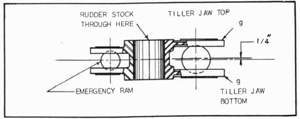
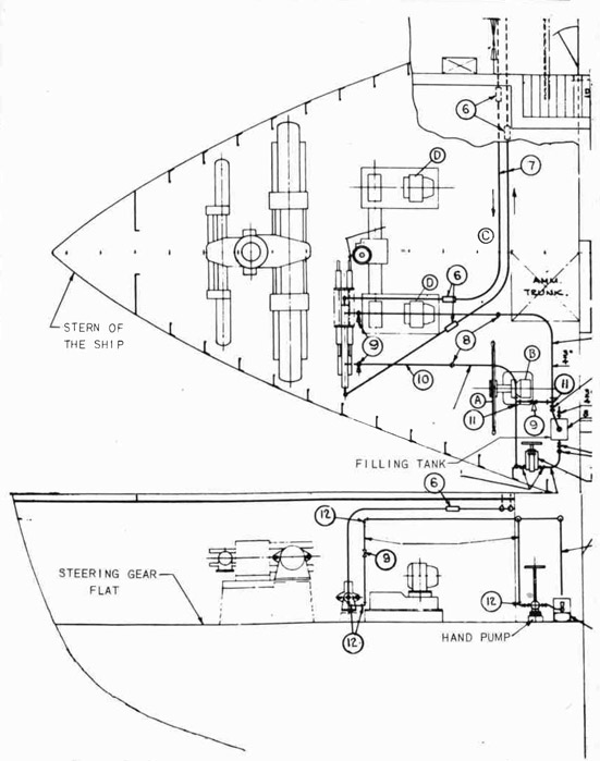
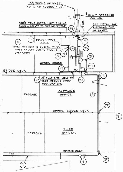
OUTSIDE MACHINIST TRAINING
INSTALLATIONS, MAINTENANCE, REPAIRS
170
This Page Blank.
171
PART III
Running a Tight Line
PURPOSE OF A TIGHT LINE
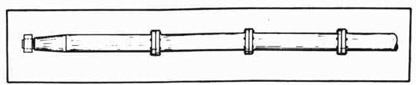
A tight line is used to locate the center line of the line shaft.
The line shaft is connected to the propeller at the stern and ends in
the engine room, an over-all distance of about 70 feet. This line
shaft, see Fig. 218, is made up of four lengths, coupled together to
form one continuous length and supported by bearings which are held securely on foundations placed at suitable intervals. The foundations
for the bearings must be secured to the tank top of the double bottom.
See Ship Terms and Locations, Part I.
Fig. 218--Line Shaft
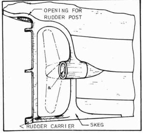
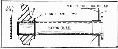
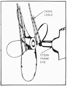
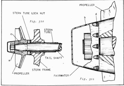
STERN FRAME
The stern frame is a steel casting which has been welded to the
stern plates of the hull, thus becoming a solid part of the ship. See
Fig. 219. The opening "a" is cast in the stern frame, and it is through
this opening or "eye" that the line shaft turns and thus turns the propeller.
Fig. 219-Stern Frame in Place
The eye must be bored out,
and the center of the bored
hole must be exactly in line
with the center line of the
keel and the correct height
above the tank top, mentioned
in the first paragraph of this
instruction sheet. Check on
this height with the leader.
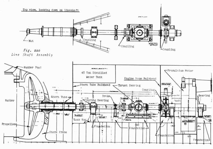
POSITION OF LINE SHAFT
In the engine room, the
center of the line may be 3'
1-1/4" above the engine bed.
This varies according to the
type of ship.
172
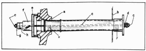
Fig. 220 - Line Shaft Assembly
173
The center of the line shaft may be 3'-8-1/4" above the thrust bearing
foundation. This also varies. Enough stock has been left in the stern
frame eye to allow for boring out. The engine foundation has been installed in the correct relationship with the center line of the ship.
There is a center line marked off on the bulkheads and deck plates of
the ship. The stern frame has been lined up with this center line and
welded in place.
CENTER OF LINE SHAFT
All that now remains to be done is to establish a center line above
the deck plates and in line with the ship center line. This is the purpose of a tight line. From this tight line, measurements are taken to
locate the spring bearing, the thrust bearing, the supports for the propulsion motor, the circle for the holes in the three bulkheads (see note)
aft of the propulsion motor, the stuffing box and the line shaft in the
engine-room watertight bulkhead, and the circle for the bored hole in
the eye of the stern tube. See Fig. 220.
NOTE: Some ships have more or less than three bulkheads at this
location, depending on the type of ship. The operation of
boring, however, remains the same in principle.
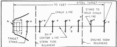
TIGHT LINE
The tight line used on this job is a piano wire, .018 of an inch in
diameter. The same size of wire and the same tension are employed each
time a "tight line" is run. On oil tankers, the length of the line is
about 70 feet from one end support to the other. On other types of
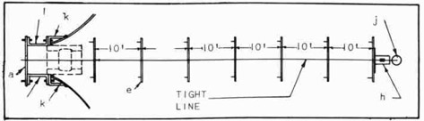
ships this distance will vary. Figure 221 shows these two supports:
A "horse" on the outer face of the "eye" and a "line target" at the
other end of the line, in the engine room. See "a" and "d".
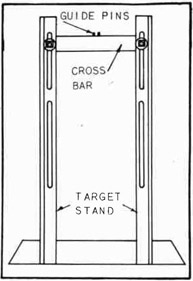
Fig. 221--Target Stands Set to Center Line of the Ship
SETTING THE TARGET STANDS OR SUPPORTS
The target is a centering device, or metal bar, which is bolted
across the two columns of an angle iron support that may be bolted or
tack welded to the deck plates or tank top. See Fig. 222. In order to
174
set the target in the correct position, a chalk line is stretched from
the engine room to the outer face of the eye at the stern, and by means
of a plumb bob and line the chalk line is located exactly above the center line of the ship. See Fig. 221.
Fig. 222-Target Stand Assembly
NOTE: The center line of the ship
was located by the shipfitters
all along the tank top and on
bulkheads with center punch
marks as the ship was being
built. The outside machinist
follows all such center lines
when laying out his work.
Figure 221 is a view looking down on
the entire line shaft location as in the
top view, Fig. 220. A "horse" 'a" is
placed across the stern-frame eye. A target stand (See Fig. 222) is set in position as at "d". The chalk line "g" is
adjusted until its position is directly
over the ship center line which was center punched on the deck by the shipfitters.
A plumb bob and line are used to determine
the correct position of the chalk line.
The distance from "a" to "d" is about 70 feet, and a target stand
is set up, as at "e", every ten feet. The chalk line gives the location for the center of the target stand and the height of the target
stand crossbar. When all the targets have been placed, the crossbars
are adjusted so that they just about touch the chalk line on the under
side. When doing this, make sure the chalk line is stretched TIGHTLY.
NOTE: All target stands are not of exactly the same construction,
but they all serve the same purpose. When the tight line
has been run and the necessary points located from the line,
the target stands are stored away for the next job. Always
store the target stands carefully, together with all bolts,
nuts, and crossbars, so that no time may be lost in looking
for this equipment the next time it is to be used.
PLACING THE TIGHT LINE
The chalk line is now removed entirely. It has served its purpose.
The support "a" is relocated for holding the tight line. See Fig. 223.
Two brackets, "k", are tack welded in place temporarily. These brackets
support two stools "l". "a" is now supported by the stools. The stools
and the bar are bolted to the brackets and may be adjusted to bring the
tight line into alignment with the ship center line.
175
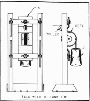
Fig. 223--Cross Bars Centered to Hold Tight Line
Fig. 224--Tension Weight and Reel
The reel and supporting bracket, "h", are bolted to the target crossbar in the engine room. See Fig. 224. Check the reel to see that it is
well oiled and running free. Check the stop screws on the reel to make
sure that the reel is locked
in all positions before locating any tram marks. The tight
line is unwound carefully and
carried back through the several openings in the engine-room bulkhead: the stern-tube
bulkhead, the bulkheads between
the stern frame and the stern-tube bulkhead, and finally
through the eye of the stern
frame where the end of the tight
line is securely fastened to the
crossbar "a". Figure 224 shows
that the reel is notched in four
or more places. The weight "j"
is hung from one of these
notches.
TENSION ADJUSTMENT
The piano wire used as a
tight line is .018 of an inch
in diameter. When this size
of wire is supported at two Fig. 224--Tension Weight and Reel
places, 70 feet apart, and stretched with a certain tension, the "sag"
of the wire will form a long, gentle curve. This curve is always the
same if the wire is supported, as above, and tightened the same amount
each time.
A 27-3/4 pound weight is used to keep the wire in tension when the
over-all distance is 70 feet. See "j", Fig. 224. The amount of sag has
been figured very carefully. It is definitely known that a tight line
always sags a certain fixed amount, according to the size and length of
the line. See illustration, Fig. 225.
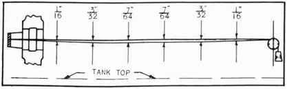
176
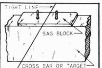
Fig. 225--Showing the Sag in a Tight Line
SAG BLOCKS
Inasmuch as it is definitely known how much a tight line sags in
ten feet, it is only necessary to raise the wire that much to make the
line level. Figure 225 gives the correct amount at every ten feet.
Figure 222 shows two small pins in the target or crossbar which is
bolted to the target stand. These pins are there to hold the sag
blocks in place and to guide the tight line along the center of the
target stands. Figure 226 is an illustration of a sag block located
in place over the two pins in the crossbar. Sag blocks of the same
thickness as mentioned in connection with Fig. 225 are used as long as
the distance between tight-line supports remains 70 feet. If this distance changes, sag blocks of a different thickness must be used.
Fig. 226-Sag Block Pins
ADJUSTING THE CROSSBAR
With the tight line in tension, the
end supports are carefully adjusted to
bring the wire directly over the ship
center line as was done with the chalk
line. This adjustment must be exact.
A plumb bob and line are used as before.
The height of the tight line at the
engine-room-target end must be according to the blueprint. This height is
usually 5' 2" from the engine room tank top to the under side of the
tight line. Check and recheck the height of the line to provide for a
chock thickness of 1-1/2" under all of the bases of the units being installed. Check with the leader.
The crossbars must now be raised and adjusted until a light shows
the bar barely touching the wire. Tighten the crossbar bolts and check
with the leader. When all the crossbars have been adjusted, place the
sag blocks on the pins and recheck at every point to make sure the adjustment is correct for height and center location. Remember the tight line
is the center of the line shaft. Measure carefully, tighten all adjusting bolts, and check with the leader.
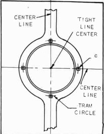
LOCATING MACHINING POINTS
Before any machining, such as boring and facing, can be permitted,
the tight line must be removed. Certain measurements have to be taken
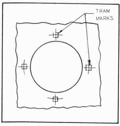
from the tight line, and markings made. Figure 227 shows the outer
177
Fig. 227--Tram Marks on Stern Frame Eye
face of the stern-frame eye. The center
of the tight line is plainly marked. Four
center punch marks must be made as shown
at points "c".
The distance of the center punch marks
from the center of the tight line should be
about one-half inch greater than the radius
of the bore in the stern-frame eye. The
reason for this is that after the eye is
bored a check may be made from these
"register" or tram marks and the accuracy
of the work thus assured. A cold chisel is
used to mark a small square around the tram
marks so that they may be easily located.
Similar measurements and center punch
marks are made at every opening through
which the line shaft will pass. It should
be quite clear that if the tight line is
run correctly and if the tram marks are
located accurately, the finished job will
be satisfactory. The slightest error
means serious trouble later.
When taking a measurement from a tight line to a tram mark, "snap"
the line to make sure it is on center. Unless this is done there is
danger that the line may be slightly to one side. Check this repeatedly.
NOTE CAREFULLY:
When measuring from a tight line with the tight line itself as
a center to a point 10" from that center, be sure to subtract
half the diameter of the tight line from the 10".
The diameter of the tight line is .018".
The radius of the circle is 10".
The measurement from the side of the tight line to one
edge of the diameter of the circle would be 10-.009, or
9.991 inches.
For any measurements from a tight line set the micrometers to allow
for half the diameter of the tight line.
QUESTIONS
1. How much does a tight line 70 feet long and .018" in diameter sag in the center if unsupported?
2. If the tight line is not located directly over the ship
center line, how will this affect the alignment of the
line shaft?
3. State the precaution which should be taken when locating
tram marks with a center punch.
4. How does the mechanic make certain that the tight line is
"on center" when taking measurements?
178
5. What device is used to hold the tight line at the proper
tension?
6. What is the correct distance from one target support to the
next?
7. Why is a chalk line run before setting the target supports?
8. Explain the reason for burning a hole larger than the
stern tube in some bulkheads.
9. How does the diameter of the tight line affect a measurement taken from the center of the tight line to the circumference of any circle scribed about the tight line as
the center?
* Removing A Tight Line
INFORMATION
The piano wire used for locating the shaft center line is comparatively expensive, and the slightest abuse can render it useless for further service. The time required to prepare another line would have to
be added to its cost in case a second tight line had to be used. If a
tight line is kinked, it is of no further use as a tight line.
MATERIALS
Tight line ready for removal
PROCEDURE
1. Unfasten the after end of the tight line from the adjustable
bracket.
2. Have one helper hold loose end of line and carry it toward the
reel which winds up the line at the other end.
3. Have a second helper apply oil to the line with a rag.
4. Turn the reel crank, and wind the line on the reel neatly until
all the wire is wound.
5. Secure the loose end by inserting it under two or three strands
of line and then pulling it up tight.
6. Wrap an oiled rag around the line on the reel and place the
reel of line in the reel box.
7. When you have finished with the line and the reel, see that
they are returned to the tool room.
QUESTIONS
1. Why must care be used in removing the tight line from the
shaft center line location?
2. Three men are used in removing the line. What does each
man do?
3. What precaution is taken before placing the reel of line
in the box?
* Adapted from "Outside Machinist", Alabama State Department of Education.
179
Setting A Portable Boring Bar
INFORMATION
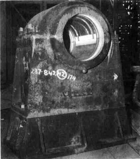
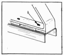
The illustration at the right, Fig. 228, shows a heavy steel casting, the stern frame, which is welded solid with the stern plates of a
ship's hull. The hole in the hub is the stern-tube housing and is called
the "eye" by shipyard mechanics.
Fig. 228--Stern Frame
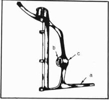
The lower portion "a" is called
the SKFG. The surface "b" is called
the outer face of the eye and "c" is
called the inner face of the eye.
The stern-tube housing must be bored
out to a certain size to fit the stern
tube. See appendix for definition of
stern tube.
Figure 220 shows a longitudinal
cross section of a ship's hull in the
bottom view. Note carefully the locations of the bulkheads, bearings, stools,
and couplings. The stools which support the shaft bearings are welded to
the tank top before the tight line has
been run. When the construction is complete, the center line of the
line shaft must occupy the same position as the tight line occupied
before it was removed.
While the tight line was in position, tram marks were accurately
located on the outer face of the eye (Fig. 227) and around the rough
hole in the stern-tube bulkhead (Fib. 220). Tram marks were located
on the engine-room watertight bulkhead and on the two bulkheads immediately forward of the stern frame.
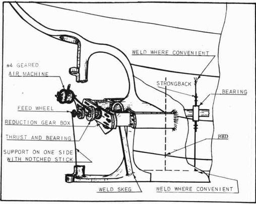
The diameter of the portable boring bar is 5" to 14". A heavy
bar is always used on large work. Always use as heavy a bar as possible to avoid spring. See Fig. 229. The diameter of the eye will
easily accommodate the boring bar. Other holes in the bulkheads have
been burned out small enough for finish-machining and at the right
location with the center line.
The eye in the stern frame is to be bored 30".
The hole in the first bulkhead forward of the eye is to be bored
31".
The hole in the second bulkhead forward of the eye is to be burned
out 32-3/4" to allow the stern tube to pass freely, but it is not bored.
If there are other bulkheads at this location, the blueprint will show
which ones are to be bored and which are to be burned.
The hole in the engine-room bulkhead is bored 32-3/4" less about
.003 of one inch. The .003 of an inch is to allow for a press fit when
pulling in the stern tube.
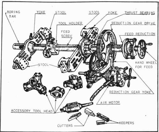
Study Fig. 229 carefully. The fittings on the main boring bar may
all be removed, leaving a bare bar. The entire assembly may be moved
backward or forward and secured in any desired location.
180
Fig. 229--A Portable Boring Bar Assembly
Four stools, Fig. 229, swivel on the yokes and have several bolt holes to
allow the yokes to be secured to a support as conditions require.
The yoke on the end opposite to the hand-feed wheel may be removed
and the bar slipped into the after end through the hole in the stern-frame
eye if the ship has twin propellers. Other parts of the portable boring
bar have to be removed while preparing to set the bar in a tight place
where one propeller is used. In this case it is lowered into the after
peak and run through the eye from the inside.
The boring bar is slung in a chain fall and passed through the eye
where a second chain fall is ready to receive it. The bar is located
by raising or lowering the chain fall; it is braced sidewise as near to
the center of the layout as possible by rough measuring. The yokes are
adjusted to a convenient position, and supports to which the boring-bar
yokes may be securely bolted are welded to the deck plates and bulkhead.
See Fig. 230. These supports are sometimes called "spiders".
After the boring bar is secured to the spiders it may be adjusted
to a location exactly central with the tram marks which were located
from the tight line.
As the main bar of the boring bar assembly is straight and true, any
measurements that may be taken from the outside diameter of the bar will
181
Fig. 230--Boring Bar Supports, Inside and Outside
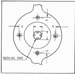
be just as accurate as if taken from the actual center of the bar. Fig.
233 shows the boring bar body lined up in the center of the four tram
marks which were put on the outside face of the eye while the tight line
was still in place. Hermaphrodites may be used to check the distance
all around the boring bar until it is exactly in the center. The same
procedure is followed at the other end of the bar where it projects
through the stern-tube bulkhead. After the bar has been securely bolted in position, the job is checked again to make sure of the alignment.
Figure 232 shows one of the bulkheads with a hole burned through.
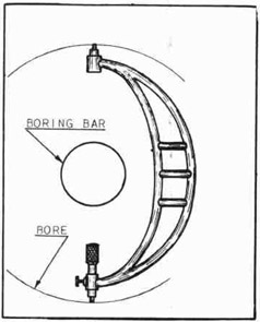
The four tram marks are measured from the tight line, and the boring bar
is lined up with these tram marks. Measurements are taken from the tram
marks as shown in Fig. 233, to the side of the boring bar as indicated
by the reversed arrows. ----> DISTANCE X <----- The distance "x" between the arrow points is the same all around the boring
bar. This measuring must be done very carefully.
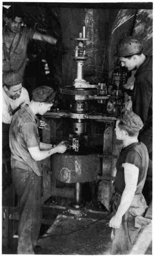
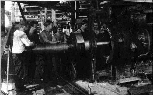
Figure 231 shows a boring bar set vertically. The men are boring
the top gudgeon on the stern post. Note the strong backs at the upper
and lower sides of the gudgeon. The strongbacks are secured to the
vertical channels welded to the rounding surface of the gudgeon.
182
Figure 230 shows a support welded to the "skeg" of the stern frame and bolted to the reduction-gear housing. This is done to hold the boring-bar assembly perfectly rigid while the boring is being done.
Fig. 231--Portable Boring Bar Set Vertical
for Boring Rudder Gudgeon
The job of setting up a portable boring bar may be summed up as follows:
PROCEDURE (Applicable in most cases)
1. Clear away all obstructions, tools, and loose materials which might interfere with the handling of the boring bar.
2. Locate chain falls and planking at convenient points for quick and safe handling of the boring bar.
3. Strip the boring bar of the yokes, tool holder, reduction-gear drive, air motor, and hand-feed.
4. Lower the boring bar into the engine room. Wrap with bagging to prevent injury to the finished surface of the bar.
5. Secure the boring bar in the chain fall previously located in the after peak, and balance the bar so that it may be swung forward. Planking
is placed to help slide the bar out through the eye in the stern frame. Protect the bar with bagging, if necessary.
6. Support the outer end of the boring bar with planking and chain fall.
7. Reassemble the yokes and other accessories, and get ready to raise the bar into boring position.
8. Estimate where additional spiders and supports should be secured to support boring bar.
9. Have flat or angle supports cut, and welded into position.
183
10. Bolt boring-bar spiders to supports, and line up the boring bar.
Fig. 232
NOTE: Measure from outside diameter of boring-bar main body to the
tram marks previously
Placed on the stern-frame
eye and bulkheads. Use a
steel scale and hermaphrodites. Keep the hermaphrodite scribing leg to a
sharp point. Re careful
to hold the tool at right
angles to the center line
of the boring bar. The
measurements must be perfect if the stern tube is
to be in correct alignment.
Check with the leader.
11. install the tool holder, adjust
the air motor, connect the air
lines, and recheck all fastenings
to make sure the bar will remain
in correct alignment. The boring
bar should now be ready for boring the eye in the stern frame.
QUESTIONS
1. A heavy boring bar should always be used where there is
sufficient room to set it up. Why is a heavy boring bar
more desirable than a light one?
2. What is the principal problem involved in setting a portable
boring bar?
3. At what points are measurements taken to bring the boring
bar central with the diameter to be bored?
Fig. 233
4. Explain the reason for
removing the fittings
from the boring bar before setting through the
stern-frame eye.
5. Point out the principal
precautions to be taken
when getting ready to
set the boring bar
through the stern-frame
eye.
6. What is the purpose of
the swivels and yokes on
each end of a boring bar?
7. Explain the usual method
of providing suitable
places to which parts of
the boring bar may be
184
bolted to hold the boring bar in position while the boring
job is being done.
8. State at how many points supports for the boring bar are
welded temporarily; explain the purpose of each support.
9. What would be the probable result if a boring bar slipped
a little during the boring operation?
10. What is the correct procedure after the boring bar appears
to be set central with the eye diameter?
Boring A Stern Frame
ACCURACY OF A BORING JOB
There must be no errors in the boring of a stern frame. The stern
frame casting is "welded in" with the hull plates of the ship, after
which operation all the pieces become one unit. To ruin a stern frame
means a loss of time and materials that is difficult to estimate. Boring a stern frame is a man-sized job which the mechanic must approach
with the fixed idea that every move must be carefully and thoroughly
planned. Mistakes are absolutely barred.
THE BORING JOB
Full instructions have been given for running a tight line. Full
instructions have been given for setting a portable boring bar. The
instructions given here are to be followed after the boring bar is in
place, ready to bore the stern-frame eye and the bulkheads, which were
shown in Fig. 220.
Fig. 234--Portable Poring Par Set Horizontal for Boring
a Stern Frame Eye
185
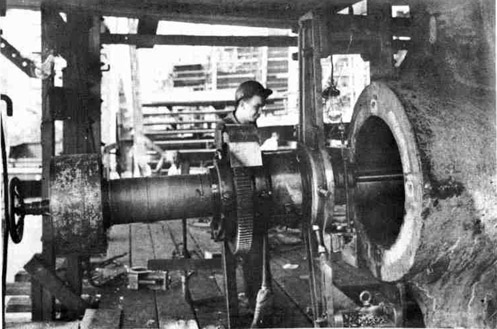
PROCEDURE
1. Adjust the tool holder and tool bit to the correct location.
Turn the bar slowly to find where the high spots are on the
inside of the eye. See Fig. 234.
2. Feed the tool into the full depth of the eye to make sure that
there is plenty of clearance and that there are no high spots
to foul the tool and throw the "set-up" out of line.
3. When everything seems to be clear, check with the leader.
4. Set the tool to take a 3/16" cut, and feed slowly to get the
"feel" of the tool. A faster feed may be used if it is evident
that the tool will "hold up" and that there is no "spring" in
the "set up." (A cutting speed of 30 to 60 feet per minute is
safe in most cases. Check with the leader on this point.)
5. Continue to take roughing cuts until the inside diameter of the
eye "cleans up".
6. Check with the leader at this point. Check all spiders, yokes,
and stools frequently to make sure there is nothing slipping.
NOTE: As soon as the hole is cleaned up, a check can be made
with hermaphrodites from the circumference of the bore
to the tram marks. This serves as a double check on
the accuracy of the work.
Fig. 235--Checking the Diameter of a
Stern Frame Bore
186
7. If the work is approved up to this point, continue boring the
diameter until within 1/8" of the correct diameter.
8. Bore the bulkheads up to this point as outlined above.
NOTE: At this point the stern tube should be brought out to
the job and carefully measured. As the diameter of the
bore in the eye must be slightly smaller than the stern
tube diameter, a very close measurement must be taken.
A very slight change in temperature affects metal
in that all metals are sensitive to heat and cold. A
stern tube that measured 30" in diameter in a warm
machine shop would very likely measure .005 less when
taken to the ship ways to be installed.
The cold air in the winter months would shrink
the metal, and it would be too small for the bored hole
in the stern frame unless the measurements were taken
when both stern frame and stern tube were the same temperature. This is the reason for bringing the stern
tube to the ship ways to be measured before the finish
cut is taken in the bore.
When measuring the stern tube to get the size and
the diameter to bore, proceed as follows:
(a) With a pair of outside calipers, carefully measure
the diameter of the stern tube.
(b) Lay the outside calipers on a level surface and set
inside micrometers to the points of the calipers.
Fig. 236
NOTE:
Special inside micrometers are used for this
job. There is an offset in the micrometer
which will clear the
boring bar. See Figs.
235 and 236.
MEASURING THE INSIDE
DIAMETER OF THE STERN-FRAME EYE.
187
(c) When the setting has been accurately determined,
reduce the size .008 to allow for a press fit.
This must be done very carefully.
(d) Now proceed with the finish cut for about 1/8"
and check with the micrometer. If the size is
correct, proceed. If too large, back off and try
again. DO NOT CUT IN LENGTHWISE FOR MORE THAN
1/8" BEFORE TRYING FOR SIZE. See Fig. 235.
Fig. 237--Finish Cut in a Stern Frame
(e) When the bore checks correctly with the mikes, proceed with the finish cut. Watch the tool carefully
as the boring proceeds. If the tool begins to burn,
STOP. Check with the leader if in doubt as to how
to proceed. See Fig. 237.
If the finished hole is bored tapering, the
stern tube will likely seize when being "pulled in";
so every precaution must be used to have a straight
hole.
NOTE: When finished with boring, do not move the boring bar
until the diameter of the hole has been checked and
approved by the leader or inspector.
188
QUESTIONS
1. When adjusting the tool holder to begin taking a cut, what
precaution should be taken to prevent the tool's "fouling"
the work?
2. How heavy should the tool be set in for the first cut in a
stern-frame eye?
3. At what speed is it considered safe to start a roughing cut?
4. What is understood by the phrase "clean up the inside diameter" of a boring job?
5. Explain the usual causes for the boring bar's getting out
of line during a boring operation.
6. How is the rough bore checked for accuracy with the center
location before proceeding with the job?
7. How much stock is left for a finish cut in a rough-bored
"eye"?
8. State the usual allowance for a press fit between the "eye"
and the stern-tube diameter.
9. Explain how the measurement is taken for the finished
diameter of the bore in the "eye".
"Pulling in" A Stern Tube
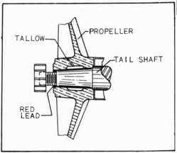
PURPOSE OF A STERN TUBE
The stern tube is the shell for the lignum vitae, tail-shaft bearing. The stern tube varies from 8 to 20 feet in length. The outside
diameter is stepped, that is, the end that fits in the stern-frame eye
is smaller than the end that fits in the stern-tube bulkhead.
CORRECT FIT FOR A STERN TUBE
When the stern-frame eye and the stern-tube bulkhead are bored to
the finished size, the stern tube should "pull in" under pressure, because the stern tube is turned .008 of an inch larger than the stern-frame eye at the stern end (see point "a" Fig. 238), and .003 larger
than the stern-tube bulkhead at the bulkhead end (See point "b", Fig.
239). Figure 239 illustrates a tube partially pulled into place.
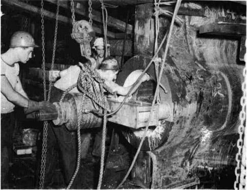
USING THE CHAIN FALLS
When the bored holes in the stern-frame eye, stern-frame bulkhead, and the intervening bulkheads have been brought to size to allow
for a pressed fit as outlined in the last paragraph, the' stern tube
is lowered into the engine room. Chain falls are placed in position
to take the stern tube off of the crane. Sometimes as many as 8 or 10
chain falls are used to carry the stern tube as it is worked back to
its place from one chain fall to another. The stern tube must be protected with bagging to prevent scoring the finished surface while the
tube is being handled by the chain falls.
189
Fig. 238--Stern Tube in Place
PREPARING TO "PULL IN" THE STERN TUBE
Figure 239 shows the stern tube partly drawn in through the stern-frame eye and the stern-tube bulkhead at "a" and "b". A heavy bolt is
shown at "c". The bolt extends from the outside of the bulkhead end of
the stern tube, through a strong back "d", and all the way through the
stern tube and the strong back "e". A hydraulic ram "f" is secured to
the outside of the strong back "e". The ram draws the stern tube into
place.
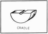
Two cradles, Fig. 240, are used under the pull bolt to keep it
exactly central in the stern-tube bore. The cradles and made an easy
fit for the stern-tube bore and the pull bolt. One cradle is placed
at the stern-frame end, and the other is placed at the stern-tube,
bulkhead end. See "x" and "y", Fig. 239.
"PULLING IN" THE STERN TUBE
The hydraulic ram works against the washer and nut at "g" and has
an effective draw of about 10 inches. When the ram has reached the 10"
limit, another washer (10") "h" is placed between the strongback and the
first washer under "g" and another 10" section of tube is drawn in. This
is repeated until the stern tube is completely drawn into place, making a
metal-to-metal joint at the stern-tube shoulder and forward end of eye.
See Fig. 238.
Fig. 239--"Pulling In" a Stern Tube
190
Fig. 240
A pressure of not less than 3500 pounds
registered on the gauge is standard for a
correct fit. This pressure may run as high
as 6000 pounds, but it must not be less than
3500 pounds. A pressure gauge is connected
to a hydraulic pump which acts on the ram.
The gauge should be watched constantly for
variations which will indicate too much or
too little pressure.
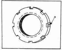
The lock nut, Fig. 241, has in the circumference, several machined notches into
which the spanner wrench fits when the nut
is being installed or removed. When the lock
nut has finally been "snugged home", a hole
is drilled in the face of the stern-frame eye and tapped out for a lock
stud. The location of this hole brings the lock stud at the bottom of
one of the notches. After the lock stud has been secured in place, tack
weld it fast. See "a" Fig. 241.
Fig. 241--Lock Nut
When the stern tube comes to the job, it is packed with sawdust to
keep the lignum vitae bearing
blocks from drying out and
cracking. Never remove the
sawdust until ready to null
the stern tube into place.
While the operation of pulling in a stern tube is proceeding, the job is inspected
and criticized by the American
Bureau of Insurance, or the
Lloyd Insurance Company, and
the agent of the shipowner.
This is done to make certain
that the job will conform to
all underwriter requirements.
The operation of pulling in a stern tube may be summed up as follows:
Planking for skids and platform
White lead and oil
Lock stud
Tight metal
191
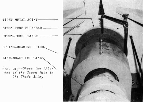
Fig. 242--Inspecting the Progress of the Stern Tube Through the Eye
Fig. 243
192
PROCEDURE
1. Lower the stern tube into the engine room.
2. Receive the stern tube in one or more chain falls, and swing
to the next chain fall, passing the tube aft.
3. Enter the tube in the bulkhead hole, and pass it through to
the stern-frame eye.
4. Apply white lead and oil to the tube, bulkhead, and eye surfaces.
5. Install the pull bolt, and adjust strongbacks and hydraulic
ram.
6. Pump pressure until the pull bolt takes hold.
7. Now examine all equipment and fastenings to make certain the
tube is entering "fair".
8. Pull the tube in as outlined in the text of this instruction
sheet.
9. When the tube is in place, check with the inspector for his
approval.
10. If approved, remove strongbacks, hydraulic ram, and pull-bolt;
clear the platform for installing the lock nut.
11. Drill through the stern-tube flange for studs, and tap holes
to suit.
12. Install studs with grommets and nuts on the after side of stern-tube bulkhead. See Part II, Making a Watertight Joint, Fig.
145 for application of stud and grommet.
13. Place a metal band around the flange of the stern tube in readiness for pouring tight metal.
14. Build up a clay mud seal all around the ring to prevent the tight
metal's escaping when it is poured into the joint.
15. Build up (on top of the metal band) a clay mud cup into which
the tight metal may be poured.
NOTE: While the metal band is being placed and the mud seal is
being installed, the tight metal should be made ready.
The tight metal is melted in a ladle over a heating
torch. The metal is considered to be hot enough to pour
if a pine stick takes fire when inserted in the melting
metal. This test indicates approximately a temperature
of 535° to 550° F.
16. Pour the tight metal into the cup previously prepared. Pour
fairly fast to insure a good joint and avoid air pockets.
NOTE: In cold weather the bulkhead and the stern-tube flange
should be preheated to prevent chilling the metal as it
is poured.
17. Remove the band and calk the tight metal with a rough calking
tool. This procedure will tighten up the joint and make certain
there are no gas or air pockets.
193
NOTE: In the event that a gas pocket or an air pocket is discovered, the metal may have to be melted out and repoured. This is almost sure to be necessary if the
pocket is found on the bottom side of the joint.
18. Install washers and nuts on the studs, and draw up tight. See
Fig. 243.
19. Fill up the after peak with water from a shore-line hose to
make the necessary test for leakage around the joints between
the stern-tube flange and bulkhead and the stern tube and
stern-frame eye.
QUESTIONS
1. Why is a forced fit necessary between a stern-tube diameter
and the stern-frame eye?
2. How much difference in diameter should there be between
the bore in the stern-frame eye and the after end of the
stern tube?
3. Explain how a stern tube is carried back into position
after 'it is lowered into the hull.
4. What protection should be given a stern tube during the
operation mentioned in step 3?
5. What is the purpose of the two cradles which are placed
under the pull bolt in the stern tube?
6. State the reason for pulling in the stern tube with a
pressure of 3500 lbs. registering on the gauge.
7. When is the sawdust removed from the inside of the stern
tube? Why is it not removed sooner?
8. When is the stern-tube job inspected and by whom?
9. What is meant by the word "fair"?
10. Why is a small space left between the stern-tube bulkhead
and the stern-tube forward flange? ("c" Fig. 238)
11. Explain in as few words as possible how and why tight metal
is poured at the forward end of the stern tube.
12. How are the stern-tube joints tested for leakage after the
installation is complete?
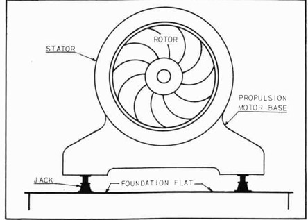
Installing A Propulsion Motor
PROPULSION MOTOR DRIVE
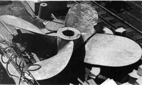
The propulsion motor is keyed to one end of the line shaft, and
the propeller is keyed to the other. When the propulsion motor turns,
the propeller turns at the same speed and so moves the ship through
the water. The propulsion motor (See Fig. 244) is electrically operated,
very much like any other electric motor except that it is installed on
the forward end of the line shaft; the line shaft thus becomes the axle
upon which the rotor turns. The foundation is installed according to
the location given on the blueprint. Figure 244 shows the motor
194
housing and the line shaft housing. The motor is inside the large housing.
Note handles which are used to grasp the housing sections when opening
or closing the housing assembly.
Fig. 244-Propulsion Motor and Line Shaft
Unless the installation of the propulsion motor is correct in the
smallest detail it will not be passed by the inspector. The propulsion
motor is lowered into the ship by ship riggers, set hack as far off on
the foundation as possible to give clearance for installing the rotor,
and after the rotor is installed
the entire stator unit is
shifted to the correct position
on the foundation.
PRECAUTION
Every precaution should be
taken when installing the stator
to make sure that there is no
damage caused to either the
rotor or the stator. It is
advisable to place shims around
the inside of the stator to
serve as guides when sliding
the rotor into place.
INSTALLING THE MOTOR
At the time the final installation is made, the line
shaft has already been installed.
See Fig. 220. The propulsion
motor must be set directly with
the line shaft for the line
shaft cannot be moved. This
calls for extremely careful
measuring. The rotor shaft is
set in line with the line shaft.
As the propulsion motor weighs
sixteen tons or more, the entire
job must be done carefully.
When the motor is set in
position and approved by the
inspector or the leader, the
job of fitting chocks is begun.
When the chocks are fitted, the
corners are drilled and reamed
for fitted bolts; the bolts are
installed and drawn down tightly; and then the rotor shaft is revolved
and "indicated" to make sure it is in perfect alignment with the line
shaft.
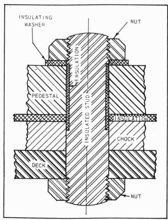
A piece of insulation approximately .125" thick is placed between
the top side of the chock and the pedestals of the propulsion motor on
the forward bearing. After the chocks are fitted and are found to be
satisfactory, they are removed and an amount equal to the thickness of
195
the insulation is machined off of the top of each chock. This job must
be done very carefully or the alignment of the other chocks will be
thrown off.
The fitted bolts through the forward bearing are insulated at the
point where the bolts pass through the pedestal and the upper side of
the chock. These points are insulated to prevent a ground on the forward bearing. See Fig. 245 and 246.
If an arcing condition should be set up, the shaft and the babbit
bearing in the propulsion motor would be scored and both would have to
be replaced. Such an arcing condition must be made impossible by proper
insulation.
TOOLS
1. Drills of the correct size
2. Corner drilling machine
3. Reamers for couplings (taper
and straight)
4. Reamers for hold-down bolts
5. Open wrench set
6. Scrapers
7. 6" scale
8. Thickness gauge (.002"-.060")
9. 24" inside calipers
Or
Special telescopic gauge
1. Find the correct location of the rotor unit
on the foundation from
the blueprint. Level the
unit on chocks or wedges,
or both, preparatory to
bolting down.
2. Align the couplings on
the rotor shaft and the
line shaft.
3. Check with the leader.
4. Fit chocks as previously
instructed (See Part I)
under the bearing pedestal of the rotor.
5. When the chocks are correctly fitted, check with
the leader.
6. If the work up to this
point is approved, proceed to drill and ream
the corner holes for
fitted bolts.
196
Fig. 246--Typical Insulated Stud Installation
7. Install fitted bolts and draw the nuts down tightly. Be sure
to install the insulated bolts correctly.
8. Check the alignment of the rotor shaft with the line shaft
to make sure there has been no error.
9. Using jacks or wedges, line the stator up with the rotor and
check the spacing between the rotor and the stator with a 12"
tapered wedge gauge. See Fig. 247.
NOTE: The propulsion motor is set "up and down" to align with
the line shaft .005 of an inch above the center. This
is to allow for wear as the motor "settles" in the bearings. The fore-and-aft location is found on the blueprint.
10. When the rotor and stator appear to be in perfect alignment all
around, check with the leader. If the alignment is correct,
fit the chocks under the stator base.
197
Fig. 247--The Stator is Jacked Up True With the Rotor
11. Drill, ream, and install fitted bolts on the four corners.
Pull the nuts up tightly. Use every precaution to insure the
nuts being pulled up to the limit.
Fig. 248--Typical Turbo--Generator Unit
198
12. Re-check the spacing between the rotor and the stator.
13. Call the leader, and have the job inspected up to this point.
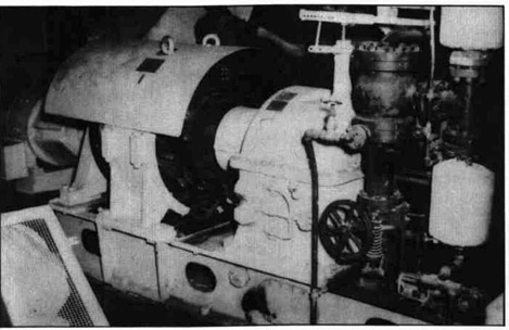
Figure 248 shows a turbo-generator and exciter set. Several of these
units are installed in the engine room or adjacent to the engine room,
and they generate power which is used to drive the propulsion motor and
numerous other electric motors throughout the ship. The ship lighting
system also draws current from the turbo-generators.
QUESTIONS
1. When a propulsion motor is being installed, why is the
rotor aligned before the stator?
2. Explain the procedure of aligning the stator with the rotor.
3. How often is the spacing checked between the rotor and the
stator?
4. Why is the stator aligned with the rotor in such a way that
the center line of the rotor is .005 of an inch above the
center of the stator?
5. Describe a diesel side jack.
Installing Fan And Motor For Air Cooler
FAN REDUCES TEMPERATURE
The temperature in the vicinity of the propulsion motor normally
varies from 150 to 180 degrees Fahrenheit. As the propulsion motor is
installed in the engine room, it is subject to high temperatures caused
by heat radiated from the steam lines and absorbed by the surrounding
atmosphere. in winter these temperatures are reduced somewhat by cooler
weather; but in summer, and in southern climates especially, the temperature around the propulsion motor must be reduced or the motor will
run so hot that it may burn the bearings.
An air cooler is installed in a convenient place; a fan and motor
are connected to the air cooler by a "circulating duct"; and the air
around the motor is drawn through the air cooler continuously, bringing
the temperature down to about 115° Fahrenheit. See Fig. 249.
CORRECT INSTALLATION
The importance of correct installation of the air-cooler fan cannot
be stressed too much. When the ship is in service, there is an extremely heavy load on the propulsion motor. If for any reason the fan and
motor should stop working, the temperature would likely go so high that
the motor windings would be in danger of burning out. If this should
happen while the ship is at sea, the results may be easily imagined.
FAN AND MOTOR UNIT
The fan-and-motor units are usually mounted on a base as one unit.
Sometimes the fan-and-motor units come separate. In either case the work
involved in making the installation is much the same.
199
Fig. 249--Westinghouse Air Cooler Unit
Figure 249 shows two pipe lines through which sea water is circulated for the purpose of cooling the air that is blown through the air-cooler unit installed above the propulsion motor housing. The air duct
from the fan to the cooler unit is at the left. The fan and motor (not
shown in the photograph) are mounted below and close to the propulsion-motor housing.
The shipfitters build the foundations; and when the unit is ready
for installation, the ship riggers place it. The location on the foundation is laid out from the blueprint by the outside machinist. The fan
may be anywhere from 38" to 52" in outside diameter. The revolutions
per minute may be about 1175 for large motors and about 1400 for small
motors. The smaller fans operate at higher speeds. The foundation is
installed on the engine-room tank top just aft of the main condenser.
Figure 250 shows a General Electric fan and motor. The motor is
indicated at "a", the blower at "b", the intake duct at "c", and the
discharge duct at "d".
Figure 251 is a photograph of a General Electric Air Cooler.
The blower discharge (hot air) is shown at "a"; the cooler tank (to
reduce temperature) is indicated at "b".
PROCEDURE
1. From the blueprint, locate the correct position of the unit
on the foundation.
200
Fig. 250--General Electric Motor and Fan
2. Level the unit on wedges preparatory to bolting down.
3. Drill the corner holes for fitting bolts through the foundation.
NOTE: Usually the unit is bolted down on metal chocks, but
sometimes a wood cushion of suitable thickness is used
to reduce vibration. (In this case metal chocks are
not used.)
4. Fit corner chocks; drill, ream, and install fitted bolts; and
draw down.
5. Fit the remainder of the chocks.
6. Have an inspector check the job for accuracy.
201
Fig. 251--General Electric Discharge Duct and
Cooler Tank
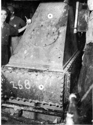
Installing A Steam Boiler
DESCRIPTION OF A STEAM BOILER
Tankers and certain types of cargo ships are usually equipped with the
boiler which is described here. The boiler is built in the shipyard by
the boiler-makers. When completely finished, the boiler is set on the
ship by the riggers and bolted down by the outside machinists.
The boiler is known as a Babcock and Wilcox, oil-fired, tubular-header type. This unit weighs approximately forty-six tons when completed. Fig. 252.
202
Fig. 252--Babcock and Wilcox Oil Fired boiler
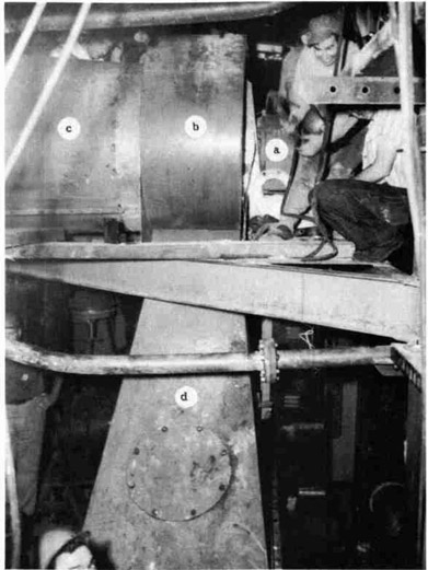
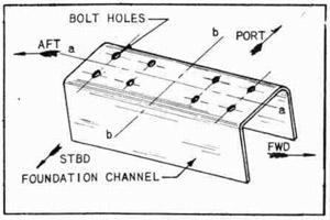
THE FOUNDATION
A foundation is constructed in the boiler room. The boiler room in
a tanker is located in the after end. The boiler room in a cargo ship
is located amidships. The shipfitters build the foundation, which is of
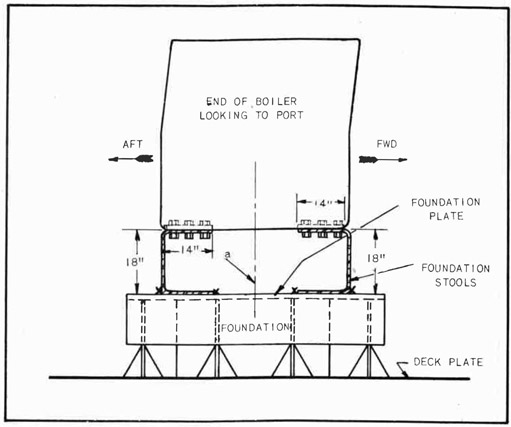
heavy construction. It is finished off with two steel channels that support the boiler, back and front. The foundation seat is a channel about
14" wide and 18" high. See Fig. 253.
The channel is welded securely to the foundation plate, and the
boiler is bolted down to the channels. The channels are called "stools".
Six 1-1/4" bolts are placed through each of the four bottom corners
of the boiler frame and the foundation stools.
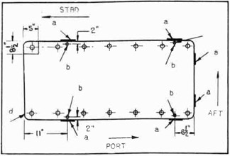
LAYING OUT THE BOLT HOLES IN THE STOOLS
The locations of the bolt holes in the stools are taken from the
blueprint. Before laying out the holes in the stools, however, boiler-makers check the base of-the boiler to make sure the holes in the base
match with the hole locations on the blueprint. If there is any discrepancy, the layout is corrected to agree with the boiler base. Figure
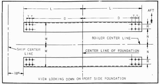
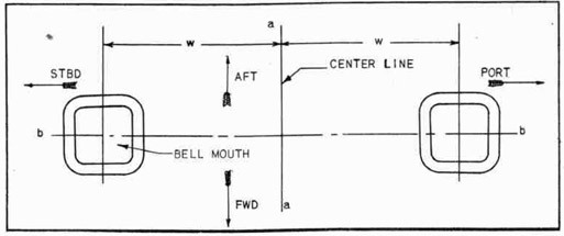
254 is a ton view of a foundation stool on the port side of the ship.
A similar foundation is on the starboard side right next to the port
foundation. Two boilers are installed with about 3 feet between the
adjacent walls.
When the machinist lays out the boiler locations, he takes all
measurements from the ship center line, the boiler center line, and the
foundation center line.
203
Fig. 253--Boiler Foundation Setting
SETTING THE BOILER
The boiler is picked up by the shipriggers and set on the foundation
under the supervision of the outside boiler-maker leader. This is not
done until after the holes are drilled in the foundation stools- A layer
of seal tight cement about 1/8" thick is spread on the surface of the
foundation stools with a trowel. When the boiler is set on the stools,
the cement forms a cushion for the boiler and seals any uneven places on
the surface. The cement hardens quickly, and thus a solid, durable joint
is formed between the foundation and the boiler base.
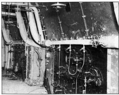
Figure 252 shows various valves, gauges, and controls which are installed by mechanics especially trained for this purpose.
PRECAUTIONS
Certain precautions must be observed when installing any of the
gauges, valves, and other parts mentioned above.
(a) Examine the fittings closely to find if right-hand or left-hand threads are cut on the connections.
204
(b) Be very careful in handling brass fittings not to damage the
fine threads.
(c) Use a wrench of the correct size on all fittings, and see that
the wrench fits closely. (Some wrenches may be "sprung" although they are stamped the correct size.)
(c) Follow the directions given by the manufacturer or the ship-building company's blueprints.
Fig. 254--Plan View of Steam Boiler Foundation
Many of these accessories appear to be simple in form and do not
seem to require any special knowledge to install. This is far from true.
Each particular piece of equipment requires correct handling and careful
treatment.
As an example of the importance of working carefully and correctly,
consider the work of installing a Bailey feed-water regulator. The
purpose of the regulator is to control the amount of water fed to the
boiler so that it will not run dry and cause burning of the tubes. The
regulator also prevents an excess of feed water which causes "wet" steam
and damages turbine fins or cracks a cylinder head.
205
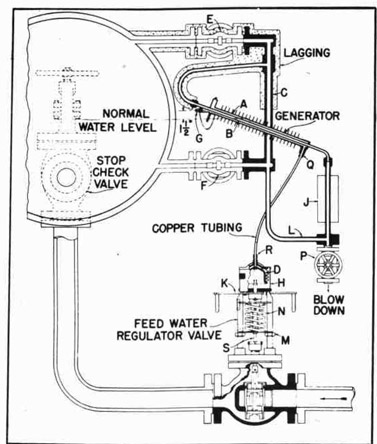
* Bailey Feed Water Regulator Instructions Principal of Operation -- See Fig. 255
The Bailey Thermo-Hydraulic Feed Water Regulator depends for its
operation upon the fact that the volume of a given weight of low pressure steam is far greater than the volume of the water from which that
steam was made. The water which operates the regulator is sealed in a
closed system formed by the annular space between the inner and outer
generator tubes, the connecting copper tubing, and the metal bellows of
the regulating valve.
When the regulator is placed in operation, heat from steam in the
upper portion of the inner generator tube causes the surrounding water
to flash into steam. This forces water out of the annular space in the
generator through the connecting tubing into the metal bellows which
expands and opens the regulating valve.
If the boiler water level tends to rise, cold water from water storage leg J rises up into the inner generator tube. This cold water plus
radiation secured from the fin surface of the outer tube causes steam in
the annular space to condense, thereby reducing the pressure in the closed
system and allowing the spring to close the regulating valve.
In normal operation, the regulation valve adjusts its position to
correspond with the rate of steaming as reflected by slight changes in
water level and a continuous feed is delivered to the boiler.
How to Fill Generator When Valve is Above Generator
1. Jack valve open by means of handjack K.
2. Disconnect tubing, R from metal bellows D.
3. Remove Guard H from bellows D, and place bellows in large
bucket full of water.
4. Compress bellows many times with open end up until all the air
is removed and bellows is filled solid with water.
5. Insert end of tubing ft in bucket of water along with bellows.
6. Remove generator plug G, and draw on opening until water syphons
from bucket out through generator.
7. Allow water to run until all air is carried out of line, and
then insert plug G.
8. With bellows under water, place Guard H over bellows and connect
end of tubing R to bellows. Make sure that end of tubing R and
bellows are completely submerged during this operation so that
no air gets into the system.
9. Replace guard H, and bellows on valve.
10. Release handjack K so that valve spring is free to close valve.
11. Remove generator plug G, and permit excess water to run out.
12. Replace plug G and make sure that connections at both ends of
copper tubing, as well as plug G, are made up tight.
* Through the courtesy of Bailey Meter Company, Cleveland, Ohio.
206
Fig. 255--Principle of Operation of Bailey Feed
Water Regulator
13. Open valves F and F, and blow down generator by opening valve P.
14. After generator has had time to cool off, regulator is ready
for service.
How to Fill Generator When Valve is Below Generator
15. if practical, remove bellows and tubing to an elevation higher
than the generator, and follow same procedure, as when valve is
above the generator. If not, jack valve open, remove tubing
R, and proceed as follows:
16. Remove bellows from valve, and insert in bucket full of water.
17. Compress bellows many times with open end up until all the air
is removed and bellows is filled with water.
18. Place end of copper tubing Q in another bucket of water, and
draw on end of copper tubing R until syphon is started.
19. Place end of tubing R in bucket with bellows, and allow water
to flow until all air has been washed out of tubing.
207
20. Stop flow of water by holding finger over end of tubing Q, and
at the same time place guard H over bellows and connect end of
tubing R to bellows. Make sure that end of tubing and bellows
are completely submerged during this operation so that no air
gets into system.
21. Replace Guard H and bellows on valve.
22. Connect end of tubing Q to generator.
23. Remove plug G from generator, and fill generator with water
until it overflows at plug.
24. Release handjack K, and allow excess water to run out.
25. Replace plug G and make sure that connections at both ends of
tubing, as well as plug G, are made up tight.
Fig. 256
26. Open valves F and F, and blow down generator by opening valve P.
27. After generator has had time to cool off, regulator is ready
for service.
28. Generator should be blown down periodically; once in 24 hours
is good practice. Also generator should be blown down whenever
regulator is placed in service after the boiler has been out of
service.
29.Spring tension on regulating valve has been adjusted at factory
so that valve begins to open when a pressure of 35 pounds per
square inch is applied to the metal bellows. This adjustment
should not be changed.
30. Do riot make up packing nut tight enough to jam valve stem. Make
up only finger-tight.
31. Make sure there is no excessive friction or rubbing of regulating valve parts. A mixture of graphite and oil applied to guides
and valve stem is helpful.
32. The water level carried by regulator is determined by location
of generator. As will be noted from a curve, the relation between water level and valve travel varies with changes in the
208
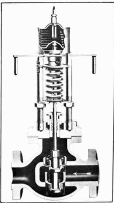
Fig. 257-Section through Bailey Feed Water Regulator Valve
boiler pressure. It may be necessary, therefore, to lower the
level of generator with respect
to normal boiler water level
for higher pressure, and to
raise it for lower presses. Under
average conditions, generator
filling plug is located 1 to
1-1/2 inches above normal water
level. When deciding on a
generator location, it is well
to estimate the gauge glass level
which will result when the valve
is in a closed position. This
may be done by following boiler
pressure line to the left-hand
edge of curve, and by reading
the distance in inches between
this intersection and the proposed line of normal gauge glass
level which will be somewhere
below the level of the generator
filling plug.
33. If regulating valve closes completely at too low a water level,
this indicates that too little
water is in the system and that
the system should be refilled.
34. If regulating valve does not
close completely until water
level gets too high, there is
too much water in system and
a small amount should be allowed to drain out.
35. Water level carried by regulator under normal load conditions
is determined largely by excess of feed-water pressure. Increasing feed-water pressure raises water level, and decreasing feed-water pressure lowers water level. Best results will
be obtained if the excess pressure shown on the valve data
sheet is maintained.
36. If regulator carries a gradually lower and lower water level,
this indicates a leak in system. If leak is not apparent, put
a teaspoonful of borax in water and refill. After regulator has
run for several hours, a grayish mark will appear at point of
leakage.
37. Never paint generator or radiator J.
38. Regulator should operate indefinitely without adding water to
generator.
39. When it is necessary to add water, close valves F and E and
open valve P. After generator has cooled, remove plug G and
209
Fig. 258 -- Section through Bailey Feed Water
Valve Body showing construction of Tight
Seating Inner Valve.
add water to overflowing. Make sure the valve is in closed
position when this is done.
40. If there is air in system, completely refill in accordance with
previous instructions. (Paragraphs 1 to 14 or Paragraphs 15
to 27.)
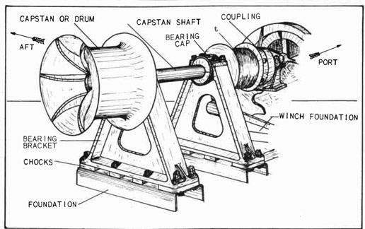
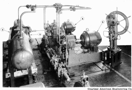
Installing Winches
DESCRIPTION OF WINCHES
A winch is a mechanically operated device which, by means of a
special arrangement of gearing and drums, pulls a rope, a cable, or a
chain at various speeds. (Fig. 259.) These ropes, cables, or chains may
be attached to the ship's cargo booms, docking hawsers, or anchors.
The winch mechanism is usually steam-operated.
The operator usually controls the winch by means of throttle and
brake mechanisms. The controls are shown clearly in subsequent illustrations.
The drums, or capstans, which are fastened to the drive-shaft extensions are correctly sloped to fit the ropes, or cables, that may be
wrapped around the drums. See Fig. 259. The small drum "t", Fig. 259,
is grooved to receive a wire cable. This drum and the drum on the port
side are sometimes used for emergency steering. When the power is
applied to the winch, the rope or cable winds up, and a pull will be
exerted upon whatever is fastened to the other end of the rope. The
object on the other end of the rope will have a tendency to move toward
the winch.
210
Fig. 259--Starboard Side of After Deck Winch
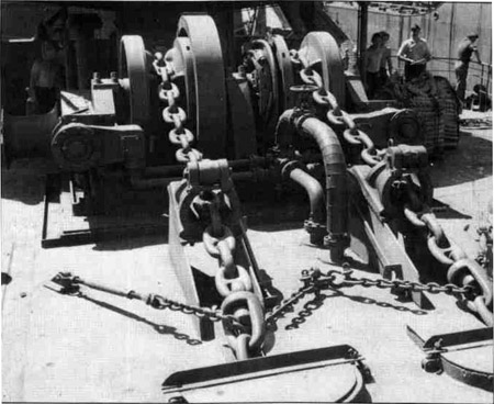
CLASSIFICATION OF WINCHES
Winches are classified according to their use or location. An
anchor winch (Fig. 260), used to raise the anchor, is located within
a reasonable distance of the anchor. A stern mooring winch, located at
the stern, is used to take on mooring lines. Deck cargo winches are
located amidships and on forward decks. As the name implies, cargo
winches are used to load and unload cargoes.
Winches are often used for purposes other than those for which they
were originally intended; for example, a cargo winch located amidships
might conveniently be used as a mooring winch, fore, aft, or outboard.
This use is made possible by means of blocks and rollers over which the
rope or cable applies its pull in a change of direction.
A WINCH SETTING
Some winches are set on special foundations; others can be set on
the foundation or skid just as built by the manufacturer. All setting
up and securing of a winch on the foundation must be done in a manner
that will not warp or bind the working parts of the mechanism. For this
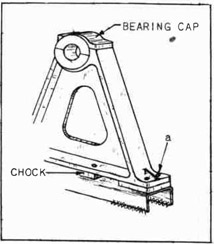
reason the locations for the bearing brackets must all be laid out carefully to the center lines, as shown on the blueprint. A typical bearing
bracket is shown in Fig. 261.
The bolt holes for the bracket feet are easily drilled from the outside of the bracket, straight down through the channel filler or base.
See "a", Fig. 261. All bracket feet are not the same in this respect.
211
Fig. 260--Typical Anchor Winch on Forward Deck
An example of another type of bearing bracket is shown in Fig. 262.
Notice that in this case the bolt hole is located under the sloping flange
of the bearing bracket at "b". The bolt holes for the feet cannot be
drilled through while the bearing bracket is in position.
Fig. 261--Bearing Bracket
SETTING AN ANCHOR WINCH
The location for an anchor winch is
laid off by the shipfitters. Flat bar
is correctly placed and welded to the
deck so as to form a band around the
winch foundation area. Flat bar is
also correctly placed and welded to
the deck around the chain locker bell
mouths. See Fig. 264.
The ship carpenters build a wooden
foundation inside of the band area
upon which the winch is to be bolted
down.
The setting of an afterdeck winch
differs in some respects from the setting of an anchor winch and will be explained fully under the heading, "Setting a Deck Winch".
212
Fig. 262--Bearing Bracket
with Inside Bolt Holes
TOOLS AND EQUIPMENT
1. Number 4 corner air-drilling machine
2. Drills
a. 1 full-length
b. 1 half-length
c. 1 12" extension
(the sizes of the
drills depend on
the holes in the
base of the winch)
3. Shipfitter's taper reamer (bolt-hole size)
4. Chalk line
5. Center punch
Fig. 263--Bolt Holes Laid Out
6. Full set of wrenches
7. 1 3/4-lb. hammer
8. 6' tape
9. 50' tape
10. Pocket knife
MATERIALS
2 round steel bars 18" long
(These bars must fit
the hole in the winch
base easily, but
snugly.
Red lead
Tarred felt
Tack Grommets
Studs Washers
Nuts
Fig. 264--Layout for Chainlocker Bell Mouths
213
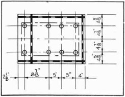
The job of setting an anchor winch may be outlined as follows:
PROCEDURE
1. Find the center between the two chain-locker bell-mouths in
the deck.
2. Snap a chalk line "a-a" fore and aft on the wood foundation,
parallel with the center line of the ship, and passing through
the center between the chain-locker bell-mouths in the deck.
See Fig. 264. Distance "W-W" is the same length.
3. Snap a second center line "b-b" at right angles to center line
through port to starboard centers of the chain locker openings.
4. Locate a fore-and-aft center line on the base of the winch.
Measure from port to starboard on the base of the winch, find
the center of the base, and center punch mark the, edge of the
base. Do this fore and aft.
NOTE: There are openings in the winch base, port and starboard,
through which the anchor chains fall so that they may be
stowed in the chain lockers below decks. These openings
must line up with the chain-locker openings in the deck.
The outboard edges of the winch base must he marked with
a center punch so that the centers of the openings in the
base can be set exactly over the line which was -snapped
on the foundation in step 3.
5. Measure the distance from the forward edge of the winch base to
the center of the chain opening in the base.
6. Lay off this distance on the outboard edges of the winch base
and mark with center punch.
NOTE: These center line marks on the winch base must correspond with the chalk line which was snapped on the wood
foundation.
7. Have the winch set by the riggers.
NOTE: The ship riggers set the winch on this foundation under
the supervision of the outside-machinist leader.
8. After the winch has been set by the riggers, go below into the
chain locker and inspect the alignment of the winch-chain holes
with the chain-locker openings. The centers when checked are
equal fore and aft and port and starboard. Adjust the winch if
necessary.
9. When the winch has been adjusted to the proper location on the
foundation, have the carpenters inspect the wood foundation.
NOTE: At this point the ship carpenter checks the fit between
the base of the winch and the wood foundation for high
spots.
10. Drill all bolt holes, using the holes in the base of the winch
as a guide. The holes are drilled through the wood foundation
and through the steel deck. Check carefully when drilling to
make sure that there are no electric cables immediately beneath the holes. Consult the leader if there are obstructions.
214
Fig. 265--Cutting the Tarred Felt Around the
Bolt Holes
11. Mark through all holes that cannot be drilled through the base
of the winch.
NOTE: Some parts of the base are heavier than others. Where
the thickness does not exceed four or five inches, the
hole locations may be marked with a pencil. Where the
thickness runs perhaps as much as ten inches, a drill
is inserted through the hole in the base and the hole
is "spotted". All the holes should have been drilled
or spotted at this point.
12. The riggers lift the winch off the foundation, and the holes
that could not be drilled before are drilled now, using the
"spotted" points to start the drill.
NOTE: The carpenter trims off the high spots of the wood at
this time to insure a good fit between the wood foundation and the winch base.
13. After all the holes are drilled, paint and soak the wood with
red lead.
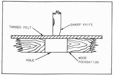
14. Cover the wood foundation surface with tarred felt, and tack
it down securely with number ten tacks. Special attention is
given to tacking the corner of each sheet of tarred felt.
(These tarred felt sheets come in rectangular pieces 2' x 4'
x 1/8" thick.)
15. Cut holes through the felt to match the bolt holes bored in
the foundation.
NOTE: Find the location of each hole with the fingers, and cut
through the felt with a sharp knife. Follow the side of
the hole in the wood foundation, and trim the felt fully
as large as the hole. See Fig. 265.
16. Have two round steel bars at hand. (See materials)
215
17. Soak the entire felt surface with red lead.
18. Have the riggers lift the winch and swing it over the foundation. Lower to within three inches of the painted surface.
19. Insert each one of the steel bars in opposite corners of the
winch base through an "open hole".
NOTE: "Open hole" means a hole that is so located that the
bar may be easily removed after the winch is set on
the foundation.
20. Swing the winch until the hole through which the steel bars
are inserted correspond with matching holes in the foundation,
and enter the bars in the foundation holes.
21. Lower the winch. The steel bars guide the winch to the correct
setting.
22. Remove the steel bars.
23. Number each hole in the base of the winch.
NOTE: Start numbering the holes at the port side forward; proceed aft and all around the winch base to the starting
point.
24. Measure the length of the bolts required for each numbered
hole, and list the sizes on a convenient scratch pad.
NOTE: Measure each hole from the top of the base to the
underside of the deck. To this dimension add sufficient
length to allow for a nut and a half-nut on the top of
the base; allow for a grommet, washer, and nut below
deck. (For example: a bolt 1-1/2" in diameter requires
2-1/2" on top and 1-3/4" below. If the "metal to metal"
length measures 8", then the total length of the bolt
will be 8" 2-1/2" 1-3/4" 12-1/4".) The leader,
however, usually checks for the bolt length. There must
be 1/2" more thread on the respective bolt ends than is
required for the thickness of the nuts.
25. Order studs from the machine shop. These studs are made of
special steel.
26. Go below deck, and with the corner air-drilling machine ream
all the bolt holes in order to take care of misalignment and
clear the holes of slivers.
27. Install all the studs beginning at the inboard holes. Tighten
each stud reasonably tight. Check with the leader.
28. Have the entire job inspected.
SETTING AN AFTERDECK WINCH
An afterdeck winch is located on the poop deck aft of the galley.
The outside machinist bolts the foundation angles to the base of the
deck winch according to the blueprint. Shipfitters lay out the location
for the winch and then set it. The shipfitters tack weld to the deck
and then brace the angles which the outside machinist bolted to the
winch base. The winch is then lifted from the angles, and the foundation is completed by the shipfitters; brackets and struts are welded
in place to stiffen and make the foundation solid.
216
When the shipfitters have completed the foundation, the outside
machinist levels off the surface of the winch base. The painters are
then notified to apply a coat of suitable protective paint. The foundation is now ready for the setting of the winch.
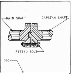
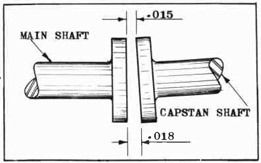
CAPSTAN SHAFTS
This type of winch is equipped with capstan shafts that extend some
distance beyond the winch. Port and starboard couplings connect the
capstan shaft to the main driving shaft. These shafts may extend for
as much as 4 feet and are supported port and starboard by one or more
bearing pedestals. The bearing pedestals (called bearing brackets)
are set to carry the capstan shaft in correct alignment with the main
driving shaft. Suitable foundations are placed under the feet of the
bearing pedestal, and they are welded to the deck. Bearing brackets
are bolted to these foundations with fitted chocks between foundations
and pedestal feet. See Figs. 252, 266 and 271.
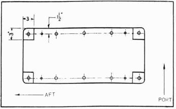
Fig. 266--After Deck Winch Showing Controls
Figure 266 shows the starboard side of an afterdeck winch. The
foot pedal "a" controls the brake. The hand lever "b" controls the motive
power. The foundations are formed in the blacksmith shop. A flat plate
approximately 1/2" thick, and of the correct size, is heated and bent
to the channel shape shown in Fig. 263. The flat top of the foundation
is then planed off level and true in the machine shop. It is on this
machined surface that the locations for the bracket feet are laid out.
In Fig. 263 are shown center lines which indicate the center of the
foundation lengthwise and crosswise, and the centers of the bolt holes.
217
TOOLS AND EQUIPMENT
1. Portable grinder
2. 8" outside calipers
3. 8" inside calipers
4. Full set of wrenches
5. Drills (diameter of the drill depends on the diameter of the bolt holes in the winch base and brackets)
6. Shipfitter's taper reamer (bolt-hole size)
7. Center punch
8. 1-3/4 lb. hammer
9. 6' tape
10. 50' tape
11. 14" second-cut flat file
12. No. 4 corner air-drilling machine
13. 14" square bastard file
14. Thickness gauge
15. C-clamps
16. Scriber
17. Dividers
18. Oilstone
19. Spoon-bearing scraper
20. Hermaphrodites
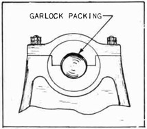
MATERIAL
Garlock packing
Chalk
Bolts
Nuts
Washers
Piece of 1-1/16" round stock 6" long
The job of setting an afterdeck winch may be outlined as follows:
PROCEDURE
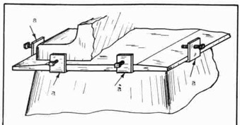
1. Procure from the shipfitter the side angles upon which the winch
is to be set.
2. Block up the winch about one foot high all around.
3. Chalk one leg of each side angle for the entire length and
clamp the chalked side to the winch base in a fore-and-aft position, one angle to port and one angle to starboard; place the
legs of the angles inboard with the edges of the angles extending beyond the winch base about 1/2". See Fig. 267. The
ends of the angles project beyond the winch base about 1-1/2"
fore and aft. Divide the distance so that the angles project
the same amount fore and aft, even if the distance is more or
less than 1-1/2".
Fig. 267--Winch Base Blocked Up for Placing Side Angles
218
4. Scribe through the holes in the winch base, and mark the locations of these holes on the angles.
NOTE: Scribing the hole locations must be done very carefully
because there is no room to use a reamer to line up the
holes after they are drilled.
5. Mark the angles on one end, and place a similar mark on the
winch base above the angles (make the mark with the center
punch). This will enable the mechanic to replace the angles
in the correct location.
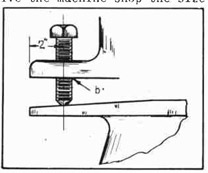
6. Remove the angles, and make four
similar punch marks, spaced equally
around the circumference of each
bolt hold circle. See Fig. 268.
Fig. 268--Marking Bolt Hole Centers
7. With the dividers, find the center
of the scribed circle. See Fig. 82
"Removing Broken Studs and Bolts",
Part I, for method of procedure.
8. Center punch the center at the
intersection of the divider lines.
9. Drill a 3/8" pilot hole through all
centers. See Part I, "Reaming
Through Holes", Fig. 64, for pilot-hole procedure.
10. Select a drill of the same diameter as the hole in the winch
base, and drill through the pilot hole.
11. Measure for the bolt lengths, and allow for a nut, plus 1/2"
beyond the actual thickness of winch base and angle.
12. Check for the proper angle location (See step 5), and bolt
the angles to the winch base.
NOTE: The shipfitters have laid out the location of the winch
on the poop deck.
13. Have the ship riggers lift and place the winch on the previously
laid out location on the deck.
14. Have the shipfitter level the winch and weld the angle edge to
the deck. The outside machinist leader checks the job for
correct installation at this point.
15. Remove the bolts, and lift the winch off the foundation so that
the foundation may be finished by the shipfitters.
NOTE: The shipfitter welds gussets, angles, and cross plates in
position to stiffen the foundation.
16. Grind off the top of the foundation all welding burrs which
might interfere with the level fit between the Winch base and
the foundation top.
17. Notify the painter, and have the foundation painted with anti-rust solution.
18. Set the winch back on the foundation. Bolt securely, and lock
all bolts with half-inch nuts.
219
19. Remove the fitted bolts from the main drive shaft of the winch,
and clean the bearing surface. Check for and remove any rough
spots with the oilstone.
NOTE: To avoid losing the fitted bolts, wire them together
and wire the bundle to the winch.
20. Check the number which is stamped on the main shaft coupling,
and find the matching number on the capstan shaft coupling.
Fig. 269--Blocking of the Capstan
21. Have the riggers block up the capstan. When this operation is
complete, line up the capstan as close as possible with the
main drive shaft. The capstan should be blocked with two wooden
wedges to prevent it from shifting.
NOTE: The inboard end of
the capstan shaft is
held temporarily by
the spigot coupling.
One bolt is placed
loosely through the
coupling to prevent
slipping. See Fig.
270.
22. Layout center lines on the
top of the channel foundation as shown in Fig. 263.
23. Locate the center of the
bearing bracket on the edge
of the base, fore and aft,
port and starboard. Center
punch these centers. See
"x" and "y". Fill. 271.
Fig. 270--Spigot Coupling Support
24. Place the bearing-bracket center
on the channel foundation center. Center the bracket on the
channel foundation fore and aft,
port and starboard, to match the
center-punch mark and the center
lines.
NOTE: Chalk the machined surface of the channel foundation so that the "lay
out" lines will stand out
clearly.
25. Scribe through the holes in
the bearing bracket. Mark the
foundations and the base of the
bearing bracket so that the
locations will not be lost.
26. Center punch the circumferences
of the holes as in step 6, and
locate center as in step 7.
220
Fig. 271--Marking the Rearing Bracket Centers
27. Center punch mark at the intersections of the divider lines.
28. Drill 3/8" pilot holes through the centers.
29. Select a drill of the same size as the diameter of the hole in
the bearing-bracket base, and drill pilot holes through.
30. Clean up the machined bearing surface on the capstan shafts, and
stone any rough spots.
31. Remove the cap from the bearing bracket, and clean any rough
surfaces carefully.
32. Apply grease to the shaft-bearing surfaces.
33. Slide the bottom half of the bearing bracket on the shaft, and
block up temporarily.
34. Place a piece of garlock packing at the top side of the shaft
on the bearing surface. This packing should be the width of
the bearing and about 1/3 of the shaft circumference in length.
Fig. 272--Placing Garlock Packing
35. Replace the base cap on the bearing
bracket over the garlock packing.
36. Bump the bearing bracket out to the
capstan hub to clear the shaft of the
hub about .030 of an inch.
37. Tighten the bearing cap on the garlock packing so as to draw the bottom
half of the bearing bracket tight to
the shaft. See Fig. 272.
38. Check the coupling between the main
drive shaft and the capstan shaft.
The bottom of the coupling should be
lined up at the bottom .003 "open",
and about .015 between the faces of
the couplings. See Fig. 273.
221
39. Check the marks on the foundation with the marks on the bearing bracket, and slide the correct foundation under the bracket. If the foundation is too high to set, have it rough-burned off until it will slide under easily.
40. Bolt the foundation to the bottom of the bracket with temporary bolts. Draw the bolts up tight.
41. Chalk the foundation about. 1" above the deck on both sides for the entire length.
Fig. 273--Coupling Face Allowance
42. Re-check the coupling for clearance as shown in Fig. 273.
43. Measure with the square, and level the foundation with the deck fore and aft.
44. Set the "morphs" to 1", and scribe on the chalked surfaces parallel lines on both sides of the foundation.
45. Remove the bolts, and remove the foundation.
46. Center punch mark the foundation along the scribed lines on both sides 1-1/2" apart.
47. Have the foundation burned off to these center-punched lines.
48. Knock off the slag and rough sides of the burned edges with a hammer.
49. Slide the foundation back to the former position under the bracket, but on the deck, leaving a 1" space between the top of the foundation and the bottom of the bracket.
50. Insert two pieces of round stock, easy bolt-hole size, through the bolt holes in the opposite corners of the bracket base and the holes in the foundation. This operation will serve to line up the foundation holes with the bracket holes.
51. With fox wedges, raise one side of the foundation until it is 1-1/16" higher than the other side, thus forming a wedge-shaped space between the foundation and the bracket base.
52. Re-check the coupling for clearance as in Fig. 273.
53. Have the welders tack all four corners of the foundation to the deck.
54. Re-check the wedge-shaped space as in step 51 to make sure that the foundation is 1/16" higher on one side than it is on the other side.
55. If correct, weld the foundation to the deck inside and outside for the entire length.
50. Place heel wedges between the foundation and the bearing bracket, two forward and two aft. The bracket is now supported on the heel wedges.
57. Remove blocking from under the capstan.
222
58. Use a piece of scrap metal to make a strongback to lay across
the bracket edge. Drill holes for the bolts. Place two bolts
long enough to pass through the strongback and reach to the
deck. Weld the bottom end of the bolts to the deck. Place
nuts and draw down tight. See Fig. 271.
59. Weld a piece of flat bar to the deck aft of bearing bracket
about 2". A hole is drilled through the plate bar for a bolt.
The bolt is used as a backing screw to prevent the bracket's
drifting aft. See Fig. 274.
Fig. 274--Using a Flatbar Stop and an Adjusting Screw
60. Check all adjustments for alignment; readjust if necessary.
61. Take chock sizes and order chocks.
62. Fit chocks.
63. Scribe holes in chocks, and have them drilled.
64. Place chocks, install the bolts, and draw down tightly. Lock
with the half-nuts.
65. Remove the heel wedges.
NOTE: Repeat on the opposite side of the winch all of the steps
herein enumerated. Both sides are worked together.
66. Re-check coupling. See Fig. 273. If the alignment is the same
as it was before, have the inspector approve the job. If the
coupling is out of alignment, the chocks will have to be refitted.
67. Drill and install 1/2" dowels on opposite corners of the bearing brackets. See Fig. 275.
NOTE: The dowels are turned .502 of an inch in diameter and
threaded for 3/4 of an inch on one end. The thread is
for the purpose of removing the dowel if necessary.
The dowel must be long enough below the thread to pass
through the bracket and the foundation. The threaded
end of the dowel must be undercut to form a shoulder,
and the end must be slightly rounded as in Fig. 275 at
"b".
223
Run a nut on the threaded end of the dowel flush
with the shoulder before starting to drive the dowel
into place. This nut will prevent mushrooming the end
of the dowel under the hammer when the dowel is driven
into place.
Drill the dowel holes with a 31/64" drill. After
drilling, ream through with a 1/2" hand reamer. The
dowel should drive in with medium force.
Fig. 275--Drive Fit Dowel
68. Remove the bearing-bracket cap,
and take out the garlock packing.
69. Clean out the bearing cap.
Clean up the shaft.
70. Grease the shaft, replace the
bearing cap, and tighten down.
71. Check with the feelers and allow
.012 of an inch clearance between shaft and bearing. If
more than .012, remove a shim.
If less than .012, add a shim.
72. Clean up feed bolts and coupling.
73. Drive fitted bolts through coupling, and draw all nuts down
snugly.
74. Drill and dowel the base of the
deck winch on the foundation.
75. Grease the entire mechanism, and prepare it for operation.
Installing A Steering Gear and Telemotor For Pilot House Indication
GENERAL DESCRIPTION OF MAIN STEERING GEAR
The main steering gear controls the position of the ship's rudder.
A ship's rudder weighs as much as 24 tons and steering the ship by hand
as is done in a small pleasure boat is not possible.
A mechanically operated device which is known as a steering gear
is installed in the after peak on a deck called the steering-gear flat.
Certain motors, pumps, and other mechanisms are installed on the steering-gear flat which control the operations of the steering gear. Control wheels are installed in the wheelhouse and on top of the wheelhouse. The wheelhouse is located on the navigating bridge deck.
Other control wheels are located on the steering-gear flat forward
of the main steering gear. The control wheels actuate the steering
mechanisms by means of hydraulic power which is transmitted from control
wheel to steering gear through a pipe line connecting the wheelhouse
with the steering-gear room. Hence, the entire installation is known
as the ship's steering gear. The port side of the forward end of the
steering-gear engine is shown in Fig. 276.
224
Fig. 276--Port Side of Steering Gear in Steering Gear Room
ALIGNING STEERING GEAR MECHANISMS
The entire steering-gear mechanism is lined up with the center line
of the rudder stock. Hence, the rudder must be placed and the rudder
stock installed before the work of installing the steering gear may begin.
Figure 277 shows the rudder (a), the rudder stock (b), the rudder
trunk (c), the carrier bearing (d), the bearing disk (e), the carrier and
brake drum (f), the tiller (g), and the keeper ring (h), installed in
position. All of these parts must line up with the rudder stock center
line fore and aft, port and starboard.
The procedure for the installation of these parts up to the point
where the installation of the steering gear commences is as follows:
1. Weld the rudder trunk (c) in position as shown.
2. The rudder is placed and the gudgeon pins installed as shown
in Fig. 277 at "z".
3. The rudder is raised and a steel block 2" thick is inserted
between the upper gudgeon eye and the rudder to hold the rudder
in this raised Position. See Fig. 277 at "x".
4. Install the rudder stock (b).
5. Install the carrier bearing (d).
225
NOTE: The carrier bearing is bolted to the rudder trunk.
6. Install the bearing disk (e).
7. Install the carrier and brake drum (f), and have the brake hand
in position on the brake drum to be connected to the brake lever
later.
NOTE: The two halves of the carrier and brake drum are not
tightened snugly until the rudder is lowered into working position.
8. Install the tiller (g).
9. Install the keeper ring (h).
10. Lift the rudder enough to remove the 2" block which was placed
to raise the rudder in Step 3.
11. Lower the rudder into position so that the rudder carrier takes
the entire weight of the rudder assembly.
12. Tighten the bolts through the two halves of the rudder carrier
and brake-drum casting, securing the carrier to the rudder
stock.
13. Swing the rudder to port and starboard and check it against
the rudder stops for the correct angle with the ship center
line. If the angle is not correct, add to or take away from
the rudder stops.
14. Bring the rudder to amidship position and secure with chain
falls from the tiller to the shell of the ship.
15. Install the packing and the split packing glands shown at "j",
Fig. 277.
INSTALLING MAIN STEERING-GEAR RAMS AND CYLINDERS
The foundations for the main steering-gear ram and cylinders are
"A" "A" "A", Fig. 279. Figure 281 shows this unit extending athwartships.
Note the two heavy bolts, "B" "B" which act as a support for the follow-up gear bearing and pinion. These bolts are shown at "B", Fig. 280 and
at "B", Fig. 282. The bolts tie the port and starboard rams and cylinders
together and ensure their correct alignment.
The foundation tops, Fig. 279, "A", "A", "A", are rough-leveled off
with a portable grinder and finish-ground with a portable surface grinder.
The surfaces of the foundation tops are ground level and smooth for a distance of approximately 10" from the edge, fore and aft. This 10" level
plane surface slopes from nothing to the outside about 1/64 of an inch,
but not more than 1/32 of an inch. A long straight edge is used to check
the amount of slope. See Fig. 287.
This procedure is carried out on all the foundation tops shown in
Fig. 279, "B"-"B", "C"-"C", "D", "E", "F", and "G".
The shipriggers pick up the main unit and lower it to the foundation
"A" "A". The unit is then leveled and brought to the correct position
fore and aft, port and starboard. The job is now ready to have the
chocks fitted and the bolts installed through the base. This main ram
and cylinder unit must be in place before proceeding to install any of
the other parts of the steering gear.
226
Fig. 277--Rudder Stock Tiller and Steering Gear
227
Fig. 278--Cast Steel Rudder Trunk
228
Fig. 279--Foundation Plan for Main Steering-Gear Rams and Cylinders
229
Fig. 280--Plan View of Steering Gear Installed on Steering Gear Flat
230
Fig. 281--Main steering-Gear Ram and Telemotor
16. inspect the position of the ram in the cylinders, and make any
necessary adjustment to bring the pivot hole in the ram to the
fore-and-aft center line of the ship.
17. Weld angle clips at convenient places to clear the corner chock
positions at points shown at "a", Fig. 286. Complete the welding of angle clips to both main ram foundations.
NOTE: Angle clips are welded to the foundations in this manner
so that heavyset screws may be used through the clips to
adjust the unit fore and aft, port and starboard. The
clips must be drilled and tapped for 3/4" bolts.
18. Drill holes for 3/4" jacking screws through the base of the
unit as shown in Fig. 289 at "b" according to the dimensions
given. See Fig. 277.
19. By means of the jacking screws through the unit base and the set
screws through the angle clips, adjust the position of the main
ram and cylinder until the athwartship center line of the ram is
at right angles to the vertical center line of the rudder stock
and at right angles to the fore-and-aft ship center line. See
Fig. 277, 90° angles. (See Fig. 280).
NOTE: Figure 290 at "g"-"g" tiller jaws, shows a dimension "n".
The distance from the top side of these tiller jaws to
the center is the same. The center of the steering-gear main cylinder must be at a point 1/4" below this
231
Fig. 282--Front View of Steering--Gear Looking Aft
center, which is between the top and bottom of the tiller
jaws. See Fig. 277 at "g", Fig. 282, and Fig. 290 at
"g".
20. Begin at the inboard, forward corners of the port foundation
("d", Fig. 286, Chock #1), and measure for chock sizes. Fill
out a chock sheet for each chock.
NOTE: The position of each chock is numbered 1, 2, 3, 4, etc.
Number each chock and its position with white paint.
Mark the position of the chock on the base of the unit.
Chock #2 is the next one to port. Follow in this direction (to port), and go completely around the foundation'
to the inboard and aft corner. Go across to the Starboard and aft corner of the starboard foundation, continue from the inboard, after corner, and go completely
around the foundation to the inboard, forward corners.
See Fig. 286 for location of the chocks. There is a
chock for every bolt hole. See Fig. 276.
21. Send the chock sheets to the shop, and order the chocks machined
according to dimensions given on the sheets.
22. When the chocks are returned to the job, begin fitting the correct chocks as follows:
232
Fig. 283--Hele-Shaw Hand--Steering Pump
233
Fig. 284--Plan and Elevation of Telemotor Copper Piping
See explanation of numbers on page 245
234
Fig. 285--Differential Follow-Up Control.
235
Fit #1 chock 1st. (See Step #5)
Fit #7 chock 2nd.
Fit #8 chock 3rd.
Fit #14 chock 4th.
(These chocks are on the port foundation.)
Fit #15 chock 5th.
Fit #21 chock 6th.
Fit #22 chock 7th.
Fit #28 chock 8th.
(These chocks are on the starboard foundation.)
Fig. 286--Port Foundation for Main Steering Ram
NOTE: Corner chocks are fitted first as outlined above because
they will then serve as a reference when fitting intermediate chocks. Example: when numbers 2, 3, 4, 5, and
6, are being fitted the base of the unit could easily he
raised and the job thrown out of line. As each chock is
fitted, the corner chocks are checked with a thickness
gauge to make sure they are tight. The corner chocks
should be checked frequently while the other intermediate chocks are being fitted.
23. Fit the intermediate chocks.
Fig. 287--Checking Foundation Top with a Straightedge
236
Fig. 288--Jacking Screws Tack Welded to Foundation Top
24. Scribe through the holes in the unit base on all eight corners,
and mark the position of the holes which are to be drilled in
the corner chocks.
Fig. 289--Adjusting Screw Through Base
25. Remove the corner' chocks, and center punch mark the circumference of each hole. Find the center of the holes with the dividers; center punch mark the centers; and send the chocks to
the machine shop for drilling. Give the machine shop the size
of holes required.
26. When the chocks are returned,
place them in position and drill
the holes through the foundation,
using the hole in the unit base
for a guide. See Fig. 61.
BILL OF MATERIALS
A partial bill of materials which goes
into the fabrication and assembly of a
steering engine is given below. To identify
the type and grade of material; compare the
key-number on the Figures 284, 297, 299,
with the bill of materials.
For example: The number 12 in the circle in Fig. 297 is found in
the column at the left in the bill of materials. Reading across from
Fig. 290--Tiller Jaw Center 1/4" Above Ram Center
237
the number, we find 3/4" standard 900 Ell, brass. In the small circles
on Fig. 297 will be found the number 12. Each number 12 on the Figure
means that the materials given opposite 12 in the bill of material are
to be used at that point.
Follow this same procedure with all the other numbers in the circles
in these three figures.
In Fig. 277 the letter "s" is found in one of the circles. This
material is 1" square packing.
Fig. 291--Pump and Motor Unit Foundation
NOTE: When because of limited
working space it is impossible to drill a full-sized
hole in the foundation,
the workman places a bushing in the hole in the unit
base and drills a pilot
hole with a small drill.
It is then possible to get
under the foundation with
a large drill and a drilling machine and drill the
hole to the full size from
below.
27. When the corner holes are drilled, ream them to size as shown
on the blueprint.
28. Order 28 fitted bolts to fit the reamed holes. Give the machine
shop the sizes of the bolts.
29. When the fitted bolts are ready, install them on all eight
corners first and draw up snugly.
NOTE: The corner bolts are fitted first to prevent any possible misalignment of the unit.
30. Scribe through the unit base holes, and mark the hole locations
on all the intermediate chocks. Locate the centers as in step
10.
31. Send the chocks to the machine shop to be drilled. Give the
shop the size of the hole.
32. When the chocks are returned, install them in the correct location and ream as in step 12.
Fig. 292--Telemotor Foundation
238
33. Install the remainder of the fitted bolts, and pull them up
snugly.
34. Install port and starboard motor and pump units "k" (See Fig. 280, Fig. 281, Fig 282) according to the blueprint.
NOTE: Follow-up gear "L" must be installed and lined up at
the same time the motor and pump units are installed.
This is done to insure the correct alignment on all
three units. These units are lined up with jacking
screws for height and position as was done when lining
up the main cylinder and ram units. See Fig. 289.
35. Fit, the chocks and install the fitted bolts as was done with
the main cylinder and ram units. See Fig. 291 for location
of bolt holes.
INSTALLING THE TELEMOTOR
Figure 284 at "p", shows two small lugs connected by a pin. The pin
must he a slip fit through both lugs, and it must slide easily. The
forward lug is connected with the follow-up gear and the after lug is
part of the telemeter leg which is connected o the telemotor.
The foundation for the telemotor is shown at "e", Fig. 279. The
telemotor is shown at "t", Fig. 277, and at "t", Fig. 280. The telemotor must be installed on the foundation and aligned with the follow-up gear. Figure 285 shows the follow-up gear and the pin at "c". See
Fig. 292 for location of bolt holes in the foundation.
Fig. 293--Telemotor Rack Foundation
PROCEED
36. Install the telemeter rack and align with the follow-up gear.
See fig 279 at "d" for location.
37. Chock the telemotor and bolt down. See Fig. 293 for location
of bolt holes.
35. Install the telemeter and align it with the telemeter rack.
39. Chock the telemeter and bolt down.
239
NOTE: Check frequently to insure the sliding fit of pin "p".
Figures 277 and 284.
40. Install the follow-up gear universal control rod "U", shown
in Figs. 277 and 280.
NOTE: Figure 292 shows two chocks at "h-h" which do not have
bolts. These chocks act as a support under the telemotor,
midway between the end chocks, and are tack welded as
shown at "w-w". Care must be taken to have the welders
tack these chocks to the foundation.
EMERGENCY, HAND-STEERING MECHANISM
Figures 277, 280, and 284 show the emergency, hand-steering cylinder
and ram. Figure 279 "R" shows the foundation for these parts.
41. Install the emergency, hand-steering cylinder and ram units,
and align the center line of the unit in the same manner as
was done in step 4 in aligning the main ram and cylinder. See
Fig. 294 for location of bolt holes.
42. Chock the unit, and bolt down.
Fig. 294--Emergency Hand-Steering Cylinder and Ram Foundation
BRAKE-LEVER UNIT
In step 7 the brake band was
installed to be connected to the
brake lever later on. The brake-lever unit is now to be installed.
Figure 279 at "f" shows the foundation for the brake-lever unit.
Figure 280 at "v" shows the brake-band connection with the brake-lever. Figure 280 also shows the
brake-lever adjusting screw at "w".
The adjusting-screw unit must be
installed at the same time as the
brake lever in order to secure a
correct alignment. Figure 303 shows
Fig. 295--Brake Foundation
240
the brake, the brake lever, and the brake-adjusting screw assembled on
the foundations, in Figs. 295 and 296.
Fig. 296- Screw Foundation
INSTALLING THE BRAKE LEVER AND SCREW
The brake lever and the brake-lever adjusting-screw units are now installed and aligned with the
brake band which was previously placed in position
on the brake drum. The brake edges must line up with
the flanges on the brake drum and not "cross" the
plane of the brake-drum flanges. When the alignment
is correct, the bottom edge of the brake should clear
the bottom flange of the Crake drum about 1/16 of an inch. The base of
each of these units is adjusted to the correct height with jacking screws.
When the alignment is correct, the chocks are fitted, drilled, reamed,
and bolted down according to standard procedure.
HAND PUMP AND FILLING TANK
Figure 298 shows a hand pump and a filling tank both of which are
parts of the telemotor system. The liquid for the hydraulic mechanism
is poured into the tank, and the pump is used to circulate the liquid
and distribute it throughout the telemotor lines. The foundation for
the pump is two 3" angles welded to the deck after the pump has been
bolted to the angles. An angle foundation for the tank is welded to
the deck, and the tank is strapped down securely.
Fig. 297--Hand-Steering Pump Foundation
HELE-SHAW HAND-STEERING PUMP
Figure 280 at "y" shows a hand
steering pump which is used for emergency steering when the electric
power fails on the main unit. Turning the hand wheel operates the
pump which in turn operates the emergency rams "R-R", Fig. 280.
The unit is bolted to the foundation, without chocks. A shim may
be used to compensate unevenness in
the foundation.
The holes in the foundation
are located from the base of the
unit which is already drilled when
received. See Fig. 297 for the
locations of the holes in the
foundation. The unit is lined up
with the bulkhead.
STEERING-GEAR CONTROL
Figure 299 shows the steering-gear control in the wheelhouse and on
the wheelhouse top. Figure 300 is a cross-section view of the base of
the steering-gear column in the wheelhouse. Figure 301 is a cross-section view of the base of the steering-gear column on the wheelhouse top.
Bosses are welded to the deck as at "a". Studs are screwed into the
241
Fig. 298--Plan and Elevation of Telemotor System in Steering
Gear Room
See explanation of numbers on Page 245
242
Fig. 299--Elevation of Telemotor Piping System Connected
with the Wheel-House Controls
See explanation of numbers on Page 245
243
Fig. 300--Telemotor Column Base in the Wheel House
bosses, and teak-wood blocks about 3" thick are placed as shown. The
forward telemotor is installed shown in Fig. 300 and bolted down.
The steering-column shaft is connected to the telemotor by means of a
clutch. either steering wheel can be used to operate the telemotor and
so control the steering gear. The forward, telemotor-unit filling tank
is installed as shown in 299.
The installation is now ready
for piping. The coppersmiths connect the piping from the forward
telemotor on the bridge to the after
telemotor. The coppersmiths also
install the piping between the filling, tank and the telemotor.
The installation is now ready
for trial operation.
Figure 302 is part of a steam-operated steering gear showing telemotor-to-throttle-valve control and
trick-wheel control.
Fig. 301--Telemotor Column Base on the Wheel House Top
Fig. 302--Steam Operated Steering--Gear
244
Fig. 303--Brake Lever Unit
See explanation of numbers on Page 245
245
EXPLANATION OF NUMBERS ON FIGURE 284
No.
1
1" Fig. (600#) - F.S. Male End Slip on Type 241-585-5
2
17 Fig. (600#) - F.S. Female End Slip on Type 214-585-5
3
1" Tubing Seamless Steel
Ex. R.Y. IPS
4
1" Welding Tee - Seamless Steel
Ex. H.Y. Pipe Thkss.
5
1" By Pass Valve F.S.
21-1-958-5
EXPLANATION OF NUMBERS ON FIGURES 298 and 299
No.
6
Coupling
C.R.S.
7
Telemotor Pipe
S.D. Copper
8
3/4" Std. Union
Brass
9
3/4" Std. Scr. Globe Valve
Brass
10
3/4" Pipe
Brass
11
3/4" x 3/4" x 3/4" Std. Tee
Brass
12
3/4" Std. 90° Ell
Brass
13
1/2" cock
Brass
14
1/2" Nipple
Brass
15
Male Connector
5/8" tube size
16
Union Nut
5/8" tube size
17
5/8" O.D. Tubing
S.D. Copper
18
Bracket
Comp. "G"
19
Coupling
Brass
20
Shaft, 1-7/16" diam.
Brass
21
Union Elbow
5/8" tube size
22
Stuffing Box
Complete
23
Flat Bar
Steel
24
Blocking
Teakwood
EXPLANATION OF NUMBERS ON FIGURE 303
No.
26
Brake Lever - C.S. 175-958
51/1 - Annealed
27
Bracket
Steel
Complete
28
Bearing
C.I.
5-930 92/3
29
Nut
Comp. "G"
37-383-551
30
Spindle
F.St.
A.R.S. Grade 42
31
Brake-Band EHD
F.St.
A.B.S. Grade ,42
32
Brake Band
Steel
Flat bar-7/8 x 1-3/4 x 14'-0" long.
33
Bracket
St.Pl
5" x 4" x 1/2" each
246
Installing A Propeller And Tail Shaft
THE PROPELLER
The propeller, Fig. 304, is usually a bronze casting weighing
approximately seventeen tons. The propeller casting is balanced, and
the hole in the hub for the tail shaft is bored in the machine shop.
A template is used when boring the propeller, the use of which should
insure a perfect fit between the tail shaft and the propeller bore.
Fig. 304--Typical Bronze Propeller
THE TAIL SHAFT IS PLACED FIRST
The tail shaft, Fig. 305, is lowered into the engine room by the
ship riggers and passed through the stern until flush with the eye. The
propeller hub and tail shaft must be free of dirt and grit when placed
together.
Fig. 305--Tail Shaft Fitted with Bronze Sleeve
247
PLACING THE PROPELLER IN POSITION
Fig. 306--Key and Keyway Aligned to Fit.
The propeller is lowered into
place by the ship riggers. Pads
have been welded at suitable locations on the ship shell to port and
to starboard. As the crane man
lowers the propeller to place, chair
falls, hung from the pads, receive
it and it is swung into place aft
of the stern-frame eye and in line
with the tail shaft. Roll the tail
shaft until the key in the taper is
fair with the keyway in the hub.
See Fig.306. The tail shaft is now
pushed out and into the hole in the
propeller hub. The lock nut is
next installed and run onto within
three inches of the after end of
the hub. See Fig. 307.
FORCING THE PROPELLER ON THE TAIL
SHAFT
Fig. 307--Lock Nut on Tail Shaft
The approved types of wedges
and boxes are then installed between
the lock nut and propeller hub for
the purpose of forcing the propeller
on to the taper of the tail shaft.
A turn of red lead is inserted
into the space (about 3/4" deep)
between the tail-shaft shoulder and
the eye diameter. See Fig. 307.
Fig. 308-Locking Device
INSTALLING A PROPELLER AND TAIL SHAFT
The nut is then run up against
the after end of the hub by means of
a heavy, special spanner wrench. A
heavy chain fall is anchored to the
skeg and hooked on to the outer end
of the spanner wrench. With a steady
strain on the chain fall and with repeated blows of a 30-lb. sledge on
the outer end of the spanner, the
machinist snugs home the lock nut
against the after end of the sternframe eye. Check with the leader
for his approval.
248
SECURING THE LOCK NUT
Fig. 309--Tail Shaft Lock Nut
The chain fall, spanner wrench, and
other equipment are now removed and returned to the tool rooms. A special
locking device is installed to prevent
the propeller lock nut from loosening.
See Fig. 308. A hole just large enough
to take the pin "a" (Fig. 308) is drilled into the after end of the propeller
hub. The hole is located in a convenient notch in the lock nut. See Fig.
309. Holes are drilled and tapped
in the lock nut to fit the holes in
the locking device, Fig. 309. The pin shown in Fig. 308 is inserted in
the drilled hole in the propeller hub, and cap screws are used to
fasten the device securely in the lock-nut notch.
Figs. 310 and 311--Fairwater Installed Over Propeller Lock Nut
SEALING THE LOCK NUT
A fairwater is installed over the after end of the propeller hub
for the purpose of sealing the lock nut and protecting it from seawater.
See Fig. 311. After the fairwater is installed, it is filled with tallow through the hole provided (b), and a pipe plug is screwed in securely. See Fig. 311. A similar hole is provided in the propeller hub
through which tallow is poured to seal the tail shaft against corrosion
should possible leaks occur. See Fig. 310 at "c".
249
After the fairwater is bolted to the propeller hub, the counter-bored, bolthead openings, Fig. 311 "d", are sealed over with cement which
prevents the loss of the bolts and also protects the boltheads from
corrosion by salt water.
The job of installing the propeller and tail shaft may be outlined
as follows:
PROCEDURE
1. Lower the tail shaft into the engine room.
2. Pass the tail shaft aft until the outer end of the threaded
portion is flush with the stern-tube lock nut.
3. Lower the propeller into place on chain falls, fair with the
stern-tube bore.
4. Roll the tail shaft until the key in the taper is fair with the
keyway in the propeller.
5. Push the tail shaft through the stern tube, and engage the
tapered bore in the propeller hub.
6. Install the lock nut, and run it on to within 3" of the after
end of the hub.
7. Draw the propeller hub on to the tail-shaft taper by means of
wedges and boxes.
8. Insert a turn of red lead between the tail-shaft shoulder and
after face of the propeller.
9. Turn the nut home by using the special spanner wrench, chain
fall, and 30-1b. sledge.
10. Remove the chain falls and other equipment, and return them to
the tool room.
11. Install the lock nut and lock key.
12. Install the fairwater.
13. Fill the fairwater recess and the propeller-hub recess with
tallow. Insert pipe plugs and make tight.
14. Cement fairwater bolthead openings.
250
Launching a Tanker
GENERAL INFORMATION
The outside machinist has several important jobs to perform before
a ship can be launched. Docking plugs must be screwed in place; the
ship's rudder must be securely locked in a central, fore-and-aft position and the propeller must be firmly held so that it cannot turn when
the ship slides into the water. In the bottom of a tanker there are
forty-seven docking plugs. See Fig. 312.
Fig. 312--Docking Plug Assembly
Metal flanges are threaded to
fit the plugs shown in Fig. 312. The
flanges are welded in openings in
the ship's bottom.
PURPOSE OF DOCKING PLUGS
The openings are located in
the bottom so that every tank in
the ship may be drained through
them. A docking plug is screwed
into the threaded hole in the flange
before the ship is launched.
While the ship is on the ways
and before the docking plugs area
finally screwed in place, lengths
of pipe equipped with valves, are
temporarily screwed in place and
the valves are closed. The tanks
are filled with water to test them
for leaks. When the tanks have
been tested and approved the valves
in the pipe lengths are opened and
the water is drained. The docking
Plug is then screwed in place by
means of a wrench which fits the
square hole in the plug. See Fig.
312. When a ship is placed in drydock the docking plugs are removed
to allow all the water or other
liquid in the tanks and bilge to drain. Oil tankers are washed out with
live steam and the accumulation of water and oil is drained out through
the docking plug openings.
LOCKING THE RUDDER
When the ship slides down the ways, See Fig. 313, there are several
thousand tons of, dead weight to control after the ship is in the water.
The rudder must be securely locked so that it can not be slammed around
by the water pressure as the ship leaves the ways. There are two ways
by means of which this is accomplished:
251
1. SECURING RUDDER WHEN THE RUDDER STOCK IS INSTALLED
The riggers install cables at the stern of the ship. The cables are
fastened from the rudder, port and starboard, to pads which are welded to
the ship shell, port and starboard. The cables are drawn up taut and
made fast.
Fig. 313--The Ship Sliding Down the Ways
On the inside of the ship, Fig. 314, chain falls are fastened to the
tiller jaws; one chain fall to port and one chain fall to starboard. The
other end of each chain fall is fastened to the ship's frame, port and
starboard. The braces take the strain as the pull of the chain falls is
exerted on the tiller jaws. With the braces in place the chain falls are
pulled up tight and locked, thus adding extra force inside the ship to
assist the force of the cables installed outside of the ship by the
riggers.
252
Fig. 314--Chain Falls Attached Tiller Jaws
2. SECURING RUDDER WHEN THE RUDDER STOCK IS NOT INSTALLED
Rudder stops are provided at the stern to prevent the rudder from swinging more than 37 1/2 degrees to either port or starboard. See Fig. 315.
When the rudder is in a central fore and aft position there is a space about 7 inches wide between the rudder stops and the rudder bumpers. The riggers install cables at the stern of the ship as before. With the rudder held exactly fore and aft, R" to 1" thick plates about 7" wide are temporarily welded in the space
left between the rudder stops and the rudder bumpers. See Fig. 315. Whichever method is used, the work is supervised and Checked by the outside machinist.
Fig. 315--Steel Plates are Welded to Rudder and Rudder Stops
HOLDING THE PROPELLER STATIONARY
The rush of water against the propeller as the ship slides down the ways is sufficient to start the propeller revolving. This must never be allowed to happen. Means must be provided to hold the propeller shaft and thus hold the propeller. Fig. 316 shows a pair of heavy bars of steel which fit around the coupling flanges of the line shaft in the shaft alley. It will be noted that the semi-circular cut-out in the center of each bar is for the purpose of allowing the bars to reach around the line shaft far enough for the bolts in the coupling flanges to pass through the bars.
253
Fig. 316--Heavy Bars and Struts to Keep the Line Shaft
From Turning
After the bars are bolted in place the lower ends of the bars are
temporarily welded to the deck and the upper ends are braced by struts
welded to the port and starboard sides of the ship shell.
When the ship is about ready for launching the docking plugs are all
screwed in and inspected under the supervision of the outside machinist.
Leaving a plug out or neglecting to screw a plug in would be equivalent
to drilling holes in the ship's bottom. Every docking plug must be
snugged home securely to prevent any possible leakage.
QUESTIONS
1. What is the purpose of a docking plug?
2. How is a docking plug flange installed in a ship?
3. Where are docking plugs located?
4. Why are docking plugs inspected carefully before the ship
is launched?
5. Why must the ship's rudder be securely blocked in place
before the ship is launched?
6. Describe the blocking operation as it is carried through
when the rudder is installed.
7. Describe the blocking operation as it is carried through
when the rudder stock is not installed.
8. Why must the ship's propeller be prevented from turning
when the ship is launched?
9. Describe the method employed to lock the propeller in position while the ship is being launched.
10. Make a list of the accidents and happenings that might take
place if any of the duties of the outside machinist, as
outlined in this lesson, were left undone.