6I1. Description of eyepiece skeleton assembly.
The eyepiece skeleton assembly (Figure 4-28)
is almost identical to the eye piece skeleton
assembly used in the Type II periscope. All
parts except the eyepiece prism and the eyepiece
lens are identical. Refer to Section L, Chapter 4,
following the procedure of Sections 4L1, 2, and
3 for description, disassembly, and reassembly.
J. EYEPIECE BOX AND MISCELLANEOUS ASSEMBLIES
6J1. Description of eyepiece box and miscellaneous assemblies. This eyepiece box and miscellaneous assemblies (Figure 4-29) are identical
to the eyepiece box and miscellaneous assemblies
used in the Type II periscope. Refer to Section
4M1 for its description.
K. PACKING GLAND ASSEMBLIES
6K1. Description of packing gland assemblies. The
packing gland assemblies (Figures 4-30, 31,
32, 33, and 34) ale identical to the packing
gland assemblies used in the Type II periscope.
Refer to Sections 4N1 to 4N13 inclusive, for
description, disassembly, and reassembly.
L. EYEPIECE WINDOW ASSEMBLY
6L1. Description of the eyepiece window assembly.
The eyepiece window assembly (Figure 4-38)
is almost identical to the eyepiece window
assembly used in the Type II periscope. All
parts except the eyepiece window are identical.
Refer to Section O of Chapter 4, following the
procedure stated in Sections 4O1, 2, and 3 for
description, disassembly, and reassembly.
341
M. FOCUSING KNOB ASSEMBLY.
6M1. Description of the focusing knob assembly.
The focusing knob assembly (Figure 4-39)
is identical to the focusing knob assembly used
in the Type II periscope. Refer to Sections
4P1, 2, and 3 for description, disassembly, and
reassembly.
N. RAYFILTER ASSEMBLY
6N1. Description of rayfilter assembly. The rayfilter assembly (Figure 4-40) is identical to
the rayfilter assembly used in the Type II
periscope. Refer to Sections 4Q1, 2, and 3 for
description, disassembly, and reassembly.
O. VARIABLE DENSITY POLAROID FILTER ASSEMBLY
6O1. Description of variable density polaroid
filter assembly. The variable density polaroid
filter assembly (Figure 4-41) is identical to the
variable density polaroid filter assembly used
in the Type II periscope. Refer to Section R
under Chapter 4 following the procedure stated
in Sections 4R1, 2, and 3 for description,
disassembly, and reassembly.
P. EYE BUFFER AND BLINDER ASSEMBLY
6P1. Description of the eye buffer and blinder
assembly. The eye buffer and blinder assembly
(Figure 4-42) is identical to the eye buffer
and blinder assembly used in the Type II
periscope. Refer to Section S under Chapter 4,
following the procedure stated in Sections 4S1,
2, and 3 for description, disassembly, and
reassembly.
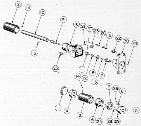
Q. TRAINING HANDLE ASSEMBLIES
6Q1. Description of the left training handle
assembly. This left training handle assembly
operates the prism tilt mechanism by the
movement of the revolving grip (3, Figure 6-11)
and is interconnected, with an appropriate
mechanism in the eyepiece skeleton assembly.
It is further interconnected by shifting wire
tapes (38, Figure 4-28) to the prism tilt mechanism and the skeleton head assembly for elevation
and depression of the head prism.
This assembly is similar to the left training
handle assembly (Figure 4-43) used in the Type
II periscope, except for various deletions, such as
the spring detent assembly and its accompanying
parts. There is also a variation in the construction of various parts. Several parts of this
assembly are used in the right training handle
assembly of the Type II periscope the handle
hinge (16, Figure 6-11) is the only part of this
assembly having a variance in construction.
Figure 6-11 shows the left training handle
assembly. All bubble numbers in Sections 6Q1,
2, and 3 refer to Figure 6-11 unless otherwise
specified.
a. Handle hinge. The handle hinge (16)
is identical to the left handle hinge (28, Figure
4-43) used in the left training handle assembly
of the Type II periscope. The alignment support
section of the handle hinge, however, does not
include the two counterbored sections for the
main body stop (31, Figure 4-43) used in the left
handle hinge (28, Figure 4-43) and the square
broached hole and opposite clearance hole.
b. Index ring. The index ring (7) is almost
identical to the index ring (6, Figure 4-43)
used in the left training handle assembly of the
Type II periscope, except for the fact that the
periphery is engraved after assembly to indicate
10 degrees depression, 0 degrees line of sight, and 45 degrees elevation.
6Q2. Disassembly. The left training handle assembly is disassembled in the following manner:
1. Remove the lockscrew (14), unscrewing
it from the tapped hole in the revolving grip
shaft (10), and carrying it out of the clearance
holes in the revolving grip (3) and the outer
collar (4).
2. Remove the assembled revolving grip
(3) sliding it off the revolving grip shaft (10),
carrying with it the revolving grip end cap (1),
revolving grip outer collar (4), revolving grip
inner collar (6), and the index ring actuating
screw (25).
3. Remove the two lockscrews (26) from the
segment stop (8), unscrewing them from tapped
holes in the revolving grip shaft (10). Remove
the segment stop (8).
4. Remove the lockscrew (14) from the fixed
grip (2), unscrewing it from tapped holes in the
handle hinge (16) alignment support section
and the fixed grip.
5. Remove the assembled fixed grip (2) with
the index ring (7) on its outer collar (5) sliding
it off the handle hinge (16) alignment support
section and carrying it off the revolving grip
shaft (10).
6. Remove the index ring (7), sliding it off the
fixed grip outer collar (5).
7. Remove the two pivot screw lockscrews
(24), unscrewing them from their contact
with the two pivot screws (23) and the tapped
holes in each hinge section side wall of the hinge
bracket (30) in its lower counterbored section
seat.
8. Swing the handle hinge (16) to the
extended position. Only in this position is there
sufficient clearance for the removal of the outer
bevel gear clutch (18) with the remaining
assembly of the handle hinge (16) from the
hinge bracket (30).
9. Remove the two pivot screws (23), unscrewing them from the tapped holes in the
hinge section side walls of the hinge bracket
(30). Remove the hinge bracket.
10. Remove the inner bevel gear clutch
(17), sliding it out of the hinge bracket (30).
11. Remove the retaining screw (13), unscrewing it from the tapped hole in the outer
bevel gear clutch shaft (9). Remove the outer
bevel gear clutch (18), and the outer bevel
gear clutch spring (12), sliding them off the
square section of the outer bevel gear clutch
shaft (9).
12. Rotate the revolving grip shaft (10)
until the small end of the taper pin (27) is
lined up with the drift clearance hole in the
handle hinge wall (16).
13. Place a drift punch of suitable size in the
handle hinge clearance hole (16).
343
Figure 6-11. Left training handle assembly.
14. Drive the taper pin (2I) from the outer
bevel gear clutch collar (11) and the outer bevel
gear clutch shaft (9).
15. Remove the outer bevel gear clutch
collar (11) from the outer bevel gear clutch
shaft (9).
16. Remove the revolving grip shaft (10)
with the assembled outer, bevel gear clutch
shaft (9) from the handle hinge (16).
17. Do not disassemble the outer bevel gear
clutch shaft (9) from the revolving grip shaft
(10). Leave them secured with the taper pin
(15).
18. Remove the retaining screw (21), unscrewing it from its engagement in the keyway
in the handle detent plunger (19) and the tapped
hole in the hinge section rear side wall of the
handle hinge (16).
19. Remove the handle detent plunger (19)
and the handle detent plunger spring (20)
from the reamed hole in the hinge section inner
circumference wall of the handle hinge (16).
20. The two segment stop adjusting screws
(29) and the two lockscrews (28) are not altered
during disassembly.
6Q3. Reassembly. The left training handle assembly is reassembled in the following manner:
344
1. Lubricate lightly all rotating parts with
Lubriplate No. 110 as the reassembly procedure
is followed.
2. Place the handle detent plunger spring
(20) in the reamed clearance holes in the handle
detent plunger (19).
3. Place the handle detent plunger (19)
and the spring (20) in the reamed hole in the
rear inner circumference wall of the handle
hinge (16). Rotate the handle detent plunger
until its keyway is located to the rear, and its
detent point is lying in a horizontal plane, so
that the retaining screw (21) engages in the
keyway.
4. Insert the retaining screw (21), screwing
it into the tapped hole with its undercut shoulder
engaging in the keyway in the handle detent
plunger (19).
5. Place the assembled outer bevel gear
clutch shaft (9) with revolving grip shaft (10)
in their respective reamed holes in the handle
hinge (16).
6. Place the outer bevel gear clutch collar
(11) on the outer bevel gear clutch shaft (9).
7. Align the taper pin holes in the outer
bevel gear clutch shaft (9) and the collar (11).
8. Insert and secure the taper pin (27) in
these lined up holes from the open hinge section
of the handle hinge (16).
9. Place the Outer bevel gear clutch spring
(12) on the outer bevel gear clutch shaft (9)
and into the counterbored section in the outer
bevel gear clutch collar (11).
10. Place the outer bevel gear clutch (18)
on the square section of the outer bevel gear
clutch shaft (9) with reference marks properly
reestablished.
11. Compress the outer bevel gear clutch
spring (12) by pressing inward on the outer
bevel gear clutch (18) for the insertion of the
retaining screw (13). Insert the retaining screw
(13), screwing it into the square section tapped
axis hole in the outer bevel gear clutch shaft (9).
12. Check the outer bevel gear clutch (18)
for free spring movement.
13. Place the inner bevel gear clutch (17)
in the reamed hole in the cored hinge section
of the hinge bracket (30).
14. Holding the handle hinge assembly in
the extended position, carry the outer bevel
gear clutch (18) through the cored clearance
hole in the hinge bracket (30).
15. Check the reference marks of the inner
bevel gear clutch tooth (17) with its mating
reference mark between two teeth of the outer
bevel gear clutch (18). Engage the gear teeth
of the inner and outer bevel gear clutches,
carrying the hinge section of the handle hinge
(16) over the hinge section of the hinge bracket
(30).
16. Apply downward pressure to the handle
hinge (16) and the handle detent plunger (19)
resting on the hinge section side wall periphery
of the hinge bracket (30). This compresses the
handle detent plunger spring fully, for the
insertion of the two opposite side pivot screws
(23).
17. Insert the two pivot screws (23) into
opposite side walls of the handle hinge (16),
check their reference marks for proper insertion,
and screw them into tapped holes in the hinge
section side walls of the hinge bracket (30).
18. Secure both pivot screws (23) with lockscrews (24). Insert these lockscrews in body
clearance holes and screw them into the tapped
hole section in each of the hinge section side
walls of the hinge bracket (30) located in the
lower counterbored section seat in its base.
The lockscrews contact the pivot screw threaded
sections to prevent them from unscrewing.
19. Place the fixed grip (2) on the revolving
grip shaft (10), sliding it on over the alignment
support section of the handle hinge (16).
20. Align the tapped lockscrew holes and
insert the lockscrew (14). This lockscrew is
screwed into the tapped hole in the fixed grip
(2) and in the alignment support section wall
of the handle hinge (16).
21. Place the index ring (7) over the revolving
grip shaft (10) and on the undercut shoulder
of the fixed grip outer collar (5). It should
fit snugly over the shoulder of this collar.
345
22. Place the segment stop (8) on the revolving grip shaft (10), secure it opposite
the semi-circular projecting section of the fixed
grip outer collar (5) to the revolving grip shaft
(10) with two lockscrews (26). These lockscrews
are inserted in countersunk clearance holes
in the segment stop (8) and screwed into tapped
holes in the above shaft.
23. Place the assembled revolving grip (3)
on the revolving grip shaft (10), carrying
with it the outer and inner collars (4 and 6),
end cap (1), and index ring actuating screw
(25). Engage the actuating screw head in the
elongated circumferential recess in the outer
side face of the index ring (7).
24. Insert the lockscrew (14), carrying it
into the clearance holes of the revolving grip
(3) and its outer collar (4), screwing it into the
tapped hole in the revolving grip shaft (10).
25. Rotate the revolving grip (3) until the
index ring (7) with its graduated line of 45 degrees
is located in the full elevated position. This
graduated line on the index ring should coincide
with the stationary index line on the fixed grip
(2). Correct the insufficient or over-travel of
the index ring by means of two segment stop
adjusting screws (29). The front adjusting screw
corrects for elevation, while the rear adjusting
screw corrects for depression. Follow the same
procedure for 10 degrees or full depression. To make
the necessary adjustments requires the removal
of the revolving grip (3).
6Q4. Description of the right training handle
assembly. The right training handle assembly
(Figure 4-44) is identical to the right training
handle assembly used in Type II periscope.
Refer to Sections 4T5, 6, and 7 for description,
disassembly, and reassembly.
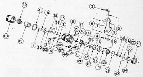
R. STADIMETER ILLUMINATOR ASSEMBLY
6R1. Description. The stadimeter illuminator
assembly may be attached to the anchor screw
pins (19, Figure 4-29) in the front or rear sides
of the eyepiece box (11). It is adjusted in such
position as to illuminate either the front or
rear stadimeter housing dials (Figure 4-24)
in an emergency, or when the observer desires
the extinguishing of the submarine control
tower lighting. The light intensity is adjustable
for varying degrees of darkness adaptation in
the observer's eye. Figure 6-12 shows the stadimeter illuminator assembly. All bubble numbers
Figure 6-12. Stadimeter illuminator assembly.
346
in Section 6R1 refer to Figure 6-12 unless
otherwise specified.
Ill. No.
Drawing Number
Num- ber Re- quired
Nomenclature
1
P-1179-26
3
Insulating plate lockscrews
2
P-1179-31
1
Contact strip lockscrew
3
P-1414-3
1
Right finger grip lever
4
P-1414-4
1
Left finger grip lever
5
P-1414-5
2
Finger grip lever springs
6
P-1416-5
2
Finger grip lever thrust stop screw pins
7
P-1416-6
2
Finger grip lever pivot screw pins
8
P-1431-1
1
Illuminator housing
9
P-1431-2
1
Housing base plate
10
P-1431-3
1
Battery cell housing
11
P-1433-1
1
Rheostat assembly
12
P-1433-1A
1
Rheostat hub locknut
13
P-1433-1B
1
Rheostat shaft retaining lock washer
14
P-1433-2
1
Bulb socket assembly
15
P-1433-9
1
Battery single cell
16
P-1433-12
2
Battery bulbs
17
P-1434-1
2
Illuminator housing spacer screws
18
P-1434-2
1
Battery center contact
19
P-1434-3
4
Bulb and rheostat mount plates lockscrews
20
P-1434-5
1
Insulating plate
21
P-1434-6
2
Illuminator housing spacing screw locknuts
22
P-1434-7
1
Stuffing gland
23
P-1434-8
1
Contact spring usher
24
P-1434-9
1
Spare bulb housing
25
P-1435-1
3
Illuminator housing screws
26
P-1435-2
3
Bulb and rheostat mount plate spacers
27
P-1435-3
1
Rheostat mount plate
28
P-1435-4
1
Bulb and rheostat mount plate key spacer
29
P-1435-6
1
Battery cell spring
30
P-1435-7
1
Bulb and rheostat mount knurled retaining ring
31
P-1435-8
1
Contact strip insulator
32
P-1435-9
1
Contact strip
33
P-1436-1
1
Rheostat assembly cover
34
P-1436-2
1
Rheostat operating knob
35
P-1436-2A
1
Rheostat operating knob lockscrew
36
P-1436-3
1
Contact strap aligning Screw.
37
P-1436-4
1
Condenser lens,
38
P-1436-5
1
Rheostat hub lock washer
39
P-1436-6
1
Rheostat assembly cover lead washer
40
P-1436-7
1
Rheostat mount plate lead washer
41
P-1436-8
1
Battery housing lead washer
Ill. No.
Drawing Number
Num- ber Re- quired
Nomenclature
42
P-1436-9
1
Condenser lens mount
43
P-1436-10
1
Rheostat operating knob taper pin
44
P-1436-11
1
Condenser lens clamp ring
45
P-1436-12
1
Red lucite filter
46
P-1-1
1
Rheostat mount plate stop pin
a. Housing base plate. The housing base
plate, (9) is made of cast phosphor bronze and is
4.190 inches in length. The upper and lower
projecting parts are similar to the base plate
(9) used in the variable density polaroid filter
assembly of the Type II and III periscopes, for
the attachment of two finger grip levers right
and left (3 and 4), and the two tension springs
(5). Refer to (9), Figure 4-41, Section 4R1, for
these upper and lower projecting sections.
The upper and lower projecting sections are
separated on opposite sides with rectangular
slotted sections, leaving a narrow center section.
This narrow center section fits between the
rear cylindrical walls of the illuminator housing
(8) with an axial adjustment clearance of
approximately 1/8 inch. This allows the housing
to be adjusted, axially, so that the position of the
lamp filament will illuminate the stadimeter
housing dials uniformly.
The lower projecting section is provided with
two tapped holes to receive two cap screws (25).
The narrow section in the center of the connecting section below the upper projecting section
is provided with a tapped hole for the third
cap screw, (25). These three cap screws (25)
inserted in three elongated holes in the three
illuminator housing lug sections, secure the
housing axially and angularly. Two tapped
holes located in opposite recesses in the rear
of the illuminator housing cylindrical periphery
(8) receive spacer screws (17) fitted with locknuts to adjust the lamp filament angularly as
desired for uniform illumination of the stadimeter housing dials.
b. Finger grip levers. The finger grip
levers right and left (3 and 4) with their two
thrust stop screw pins (6) and the two pivot
screw pins (7) are identical to the finger grip
levers right and left (1 and 2, Figure 4-41) and
347
their thrust stop screw pins (13) and pivot screw
pins (14) used in the variable density polaroid
filter assembly of the Type II periscope. Refer
to Section 4R1.
c. Illuminator housing. The illuminator
housing (8) is made of cast phosphor bronze
and is 3 1/4 inches in length. The external surfaces
of this housing follow an irregular cast design
from the main cylindrical body on opposite
ends. Its left cylindrical body has a cast projection extending upward sufficiently to serve as a
container. This cast projection is drilled a depth
of 7/8 inch and is provided with a coarse thread
to receive a left-hand housing (24) containing
a spare battery bulb (16).
The housing from the cast projection slopes
downward to form a hood arrangement between
its two cylindrical body sections in the central
part. The two cylindrical body sections are
separated by a space of 7/8 inch. This hood
arrangement leaves a narrow wall with a
raised boss in the left side to accommodate an
elongated hole for a cap screw (25). The hood
arrangement follows a convex contour in a
distance of approximately 120 degrees, at which point
it slopes inward at an angle of about 24 degrees.
The inward sloping section is spotted with a
router in the inner wall section of the hood
arrangement, with a counterbored and internal
threaded section to receive the condenser lens
mount (42). This section is counterbored to
receive the large shoulder of the condenser lens
mount (42), with the remaining sides of the
cylindrical body sections having a cored concave seat. The cored convex seat allows clearance for adequate divergence of the illuminated
light beam projecting downward and inward.
Two projecting lugs extend downward on
opposite sides of the bored and internal threaded
condenser lens mount opening and each cylindrical body section to form the rear flat-wall
section extension. Each projecting lug has an
elongated hole for insertion of cap screws (25).
The left cylindrical body section is undercut
and threaded to receive a lead washer (41)
and battery cell housing (10). The inner surface
of this left side is provided with two counterbored
sections. The small section of shallow depth
carries an insulating plate (20) which is secured
with three lockscrews (1). These lockscrews are
inserted in countersunk clearance holes in the
insulating plate (20) and screwed into tapped
holes in the small counterbored seat. The large
counterbored section accommodates sufficient
clearance for a single cell battery (15).
The right cylindrical body section is undercut
and threaded to receive the bulb and rheostat
mount knurled retaining ring (30), which
retains the rheostat assembly cover (33) and
rheostat mount plate (27). The inner surface
of this right side is counterbored with a 45 degrees chamfer in its seat to provide clearance for the bulb
socket assembly (14). The inner circumference
of the counterbored section is provided with a
milled recess for the bulb and rheostat mount
key spacer (28), which serves to designate its
correct assembly.
The center section between the left and right
side counterbored sections in both body sections
is cored with a semi-circular section bounded on
both ends with narrow raised boss sections
located directly opposite. This semi-circular
section carries a contact strip insulator (31)
to prevent the battery from grounding to the
illuminator housing.
The rear part of the housing between the two
cylindrical body sections is machined flat as
are also the two projecting lug sections. This
allows it an axial adjustment on the housing
base plate (9) by means of the three elongated
holes in the two projecting lug sections and
the upper narrow wall and raised boss section
above the hood arrangement.
d. Spare bulb housing. The spare bulb
housing (24) is made of phosphor bronze and
is 1/2 inch in length. The large outer diameter
is rough diamond knurled to offer a firm grip
to the observer. The outer face has the letters
Spare Lamp inscribed on it, and is filled with
white monofil, in order to be clearly visible
to the observer. The undercut section is threaded
with 12 threads per inch and engages into the
coarse tapped hole in the upper projecting section
of the left cylindrical body section of the illuminator housing (8). The inside axis of the bulb
housing has a tapped hole for an American
national miniature thread to receive the threaded
periphery of the spare bulb.
e. Battery cell housing. The battery cell
housing (10) is made of brass rod and is 2 1/32
348
inches in length. The outer diameter is uniform
its entire length with a knurled band 1/16-inch
wide near its outer end. The outer sharp corner
is rounded off.
The inner part is bored to carry the battery
cell (15) of a loose fit. It is provided with a
counterbored section 1 3/16 inch long to reduce its
weight, and is provided, with an undercut trap
1/16 inch in width to retain the battery cell
spring (29) within 1/8 inch of the outer side wall.
The inner end is counterbored a depth of
1/8 inch and is threaded to engage on the threaded
periphery of the illuminator housing (8) left
side against a lead washer (41).
f. Insulating plate. The insulating plate
(20) is made of 1/8-inch Bakelite and is shaped
cylindrical. It is a sliding fit in the small shallow
counterbored section in the left side of the
illuminator housing (8) and is secured with three
lockscrews (1). These lockscrews are inserted
in countersunk clearance holes in the outer face
of this insulating-plate and screwed into tapped
holes in the counterbored seat.
It carries the battery center contact (18)
mounted in its axis. The inner face of this plate
carries the contact strip (32) secured with an
aligning screw (36), contact strip washer (23),
and lockscrew (2). The lockscrew (2) inserted in
a hole in the contact strip (32) extends into the
axis tapped hole in the battery center contact.
The contact, strip (32), which is 1 5/16 inches
long and extends the entire length of the center
axis section in the illuminator housing (8),
is properly insulated from grounding with the
illuminator housing by means of the contact
strip insulator (31). The contact strip is chromium plated and serves as a reflector.
g. Bulb socket assembly. The bulb socket
assembly (14) is directly connected electrically
with the rheostat assembly (11). It is a commercial product consisting of a bulb socket and finger contact attached to a 1/8-inch Bakelite
insulating plate. The insulating plate is supported by the rheostat mount plate (27) and
is separated from it by three bulb and rheostat
mount plate spacers (26) and a bulb and rheostat
mount plate key spacer (28). It is secured with
four lockscrews (19). These lockscrews are
inserted in countersunk clearance holes in the
rheostat mount plate (27), and extend through
clearance holes in each of the three bulb and
rheostat mount plate spacers (26) and one bulb
and rheostat mount plate key spacer (28) to
screw in the insulating plate of this bulb socket
assembly. The rheostat assembly (11) axis
section fits through the axis clearance hole in
the rheostat mount plate (27). This plate is
provided with a stop pin (46) which is a drive
fit in a reamed hole located 15 degrees from the vertical
centerline and an appropriate distance from its
center axis. This stop pin (46) extends through a
clearance hole in the rheostat coil plate of the
rheostat assembly, and restricts the rheostat
resistance contact finger from further rotation
for a known OFF position inscribed on the
rheostat assembly cover (33) with a reference
line on the rheostat operating knob (34).
h. Rheostat assembly cover. The rheostat
assembly cover (33) is made of brass and is
27/32 inch in width. It is provided with three
external shoulder sections. The large diameter
shoulder is counterbored a shallow depth to carry
a lead washer (39) in its outer face to provide a
negative ground for the battery, and contacts
the inner counterbored seat of the knurled
retaining ring (30). The medium diameter
shoulder section is a sliding fit in the bored
opening of the retaining ring, while the small
diameter shoulder section is chamfered to
a diameter which is coincident with the large
diameter of the rheostat operating knob (34).
The chamfered shoulder periphery is inscribed
with the letters OFF and filled with white
monofil to designate to the observer the OFF
position of the illuminator as indicated by the
rheostat operating knob reference line.
The center axis is provided with a clearance
hole which is a sliding fit over the rheostat hub
threaded periphery, and has a counterbored and
threaded section in the outer part. This counterbored section allows sufficient clearance for the
attachment of the rheostat hub lock washer
(38) and rheostat hub locknut (12). This cover
is secured to the rheostat mount plate (27)
in direct relation to its inscribed OFF designation with the rheostat operating knob (34)
reference line. The internal threaded section
receives a stuffing gland (22) which locks the
rheostat hub lock nut (12).
i. Stuffing gland. The stuffing gland (22)
is made of phosphor bronze and is shaped
349
cylindrical. Its outer periphery is threaded to
engage in the internal threaded section in the
rheostat assembly cover (33). Its center axis is
provided with a reamed clearance hole, a sliding
fit over the projecting section of the rheostat
assembly shaft. The inner face is countersunk
to provide clearance over the rheostat shaft
retaining lock washer (13). The outer face is
provided with two opposite drilled holes for the
insertion of a special wrench. This stuffing
gland serves to prevent moisture from entering
the rheostat assembly, and also serves to lock
the rheostat hub locknut (12).
j. Rheostat operating knob. The rheostat
operating knob (34) is made of black bakelite
with a clearance hole in its inner axis, and is a
sliding fit on the rheostat assembly shaft
secured with a taper pin (43) and lockscrew
(35). The knob has two shoulder sections, the
large shoulder coincides with the chamfered
shoulder section of the rheostat assembly cover
(33) and is filleted with the octagon shoulder
section.
k. Bulb and rheostat mount knurled
retaining rings. The bulb and rheostat mount
knurled retaining ring (30) is made of brass and
is 0.570 inch in width. It is shaped cylindrical,
with the periphery rough diamond knurled to
offer the observer a firm grip. The outer 1/16 inch
of the periphery is undercut, with the sharp
corner rounded off.
It is bored a sliding fit over the medium
shoulder section of the rheostat assembly cover
(33), and is provided with two counterbored
sections. The small counterbored shoulder section
is provided with clearance over the large diameter of the rheostat assembly cover (33) while
the large counterbored and threaded section fits
over the rheostat mount plate (27) and engages
on the threaded periphery section on the right
side of the illuminator housing (8) to secure the
rheostat assembly with a good negative battery
ground against the lead washer (39).
l. Condenser lens mount and lens. 1.
Condenser lens mount. The condenser lens
mount (42) is made of brass and is 1 3/64 inch
wide. It has an undercut shoulder section which
serves as an alignment support section for its
entry in the internal threaded section in the
illuminator housing (8). Its large diameter has
a threaded periphery to engage in the internal
threaded section in the illuminator housing,
and rests, against the counterbored seat.
The mount is bored for the illuminated light
transmission and is counterbored, leaving a
narrow shoulder seat. The smooth part of this
counterbored section carries the red lucite-filter
(45) and the condenser lens (37), while the internal threaded section carries the threaded clamp
ring (44). The outer face of the mount is provided
with opposite slots for the insertion of a special
wrench.
2. Condenser lens. The condenser lens (37)
is made of one optical element consisting of a
plano convex crown element. It is mounted in
the condenser lens mount (42) with the plano
side resting against the red Lucite filter (45),
and is secured with a clamp ring (44).
m. Red Lucite filter. The red lucite filter
(45) is shaped cylindrical with parallel faces
and is placed in the condenser lens mount
(42) below the condenser lens (37). This red
filter presents a red beam of light to the stadimeter housing dials. The light intensity is adjustable by counterclockwise rotation of the
rheostat operating knob from maximum intensity
to minimum intensity as desired by the observer.
n. Clamp ring. The clamp ring (44) is
made of brass and has a nominal thickness and
width. The periphery is threaded and engages
in the internal threaded section in the condenser
lens mount (42) to secure the red lucite filter
(45) and condenser lens in the seat of the mount.
The inner face is chamfered at 30 degrees and rests
against the convex surface of the condenser lens
(37). The outer face is provided with two
opposite slots for the insertion of a special
wrench.
o. Electrical circuit. The negative side
of the battery cell (15) is grounded to the
battery cell housing (10) by a battery cell
spring (29) and the illuminator housing (8) with
a lead washer (41). The positive battery terminal
feeds through the center contact (18), contact
strip (32), and contact finger of the bulb socket
assembly (14) to one side of the bulb (16).
The other side of the bulb feeds through the
rheostat assembly (11) and grounds to the
illuminator housing (8) completing the circuit.
350
S. OPTICAL SYSTEM
6S1. Principles of periscopic systems. The principles discussed in Section 4U1 apply equally
well to the Type III periscope except as noted
below:
1. Magnifying power. While the over-all
power of the Type II and III is the same, the
Type III has a different arrangement of telescopes for obtaining the high and low powers
(6X and 1.5X). Omit, therefore, the list of
component telescopes in section 4U2-b, and
substitute the following list:
Type III Periscope
Low Power
High Power
Galilean telescope
1/4 X
Out
Upper main telescope
1/4.7 X
1/4.7 X
Lower main telescope
28 X
28 X
PERISCOPE (Combined product)
1.5 X
6 X
2. Field of view. The apparent field of view
and the true field of view are the same in the
two types discussed so far; however, the head
prism in the Type III can be elevated only far
enough to raise the line of sight 45 degrees above horizontal, thus, the limits of the field are different
in the present instrument. Refer to section
6S1-4 for complete data. Also, since the Type
III periscope does not have the two one-power
auxiliary telescopes, omit Section 4U1-c.
3. Image brightness. Omit Section 4U4
and substitute the following details. Since
there are five fewer lenses in the Type III, we
may expect this periscope to transmit more light
than the Type II. Less light is lost by absorption
and reflection.
a. Absorption-reflection losses. The reflection loss at the successive air-glass surfaces may
be calculated approximately on the basis of the
Fresnel theory, by assuming that about 4.1
percent of the incident light is lost at each air-crown glass surface and about 5.6 percent at
each air-flint glass surface. The number of such
surfaces are shown in the following table. A
further reflection loss occurs at each of the two
silvered glass surfaces (head prism and eyepiece
prism), and this amounts to about 6 percent at
each, or 11.64 percent for the two (=1.0000
- 0.8836).
In addition, there is the light lost due to absorption by the glass, the total axial thickness of
which in the Type III is 222 mm in low power
and 213 mm in high power. Assuming that
about 0.1,percent of the incident light is absorbed
by each millimeter of glass path, we arrive at
the absorption loss shown in the table.
By multiplying the transmission (= 100
percent minus the percent of loss) values
together, we find that the overall theoretical
transmission of the periscope is 19.2 percent in
low power and 24.4 percent in high power. These
values may also be called the transmission
efficiencies, since the incident light was taken
as 100 percent.
Type III Periscope
Low Power
High Power
Total axial thickness, glass
222mm
213mm
No. of air-crown surfaces
14
14
No. of air-flint surfaces
12
8
No. of silvered surfaces
2
2
TRANSMISSION that would result if loss were due to:
Absorption by glass
77.80% *
78.70%
Reflection, air-glass
27.87% **
35.09%
Reflection, silvered-glass
88.36% ***
88.36%
Uncoated theoretical TRANSMISSION
19.2% ****
24.4%
Uncoated Measured TRANSMISSION
19.5%
25.2%
Measured TRANSMISSION (Coated optics)
43.6%
50.9%
* 100 % - (222 mm X 0.001) = 0.778 = 77.80% (absorption loss).
** (1.000 - 0.041)14 X (1.000 - 0.056)12 = 0.2787 = 27.87%.
*** (1.00 - 0.06)2 = 0.8836 = 88.36%.
**** (0.7780) X (0.2787) X (0.8836) = 0.192 = 19.2%.
The actual measurements of transmission for
coated and uncoated optical elements were
compiled from the measurements of several
trained technicians using a Lummer-Brodhun
type photometer. The measured values above
are the averages of their results.
b. Effect of pupillary size. Since the exit
pupil of the Type III periscope is also 4 mm
(either low or high power), refer to Section
4U1, b.
c. Central and oblique brightness. Essentially the same considerations are involved
here as in the Type II. Refer to Section 4U4, c.
A comparison of the ray tracing diagram for
351
each type, however, will disclose that the
objective lens of the upper main telescope
is filled with ray-bundles in the Type III
periscope (Figure 6-13, page 288), while in the
case of the Type II only the central area (112
mm diameter) of the free aperture (144 mm)
is used. The reasons for this situation are
discussed in the following.
It must be realized that the classification of
submarine periscopes into Types I (now obsolete), II, III, and IV occurred some time after
the periscopes were actually designed and
built. For instance, the periscope (88KA40/1.99)
now known as the Type III was actually in use
before the Type II periscope (91KA40T/
1.414HA) was designed. Hence, since the optical
arrangement of the Type III is simpler than
that of the Type II, and since much of the
optical design of the Type II is actually a
carry-over from the Type III, it might be easier
for some students to study the Type III before
investigating the principles of the Type II.
As mentioned in Section 4U3,c, the over-all
length of a submarine periscope is a most
important part of the design. Thus, when the
Type III was modified to arrive at the design
of the Type II (which carries the two one-power
auxiliary telescopes in order to achieve the
ultra-narrow upper reduced tube section), it
was necessary to reduce the distance between
the two main telescopic systems so that there
would lie room for the reduced-tube optics.
A comparison of the optical assembly drawings
for the two instruments shows that this inter-objective distance was 7300.5 mm in the Type
III and is only 6091.8 min in the Type II, a
decrease of over 1200 mm or about 4 feet.
Shifting the upper main telescope system
down the tube, however, would produce an
undesirable reduction of the exit pupil of the
periscope as follows: Shortening the inter-objective distance causes the oblique ray-bundles
traveling down the tube from the upper main
objective to meet the lower main objective
before they are far enough from the optical
axis to fill the free aperture of the latter lens.
If the entire aperture of the lower-main objective
is not filled with light, its image (the exit
pupil of the periscope) will not be filled with
light, causing a smaller exit pupil and a dimmer
image.
During the design of the Type II, then, it was
necessary to change the direction of these oblique
bundles so that the lower-main objective's free
aperture would be fully illuminated. This was
accomplished by modifying the curvature of the
collective of the eyepiece system of the upper
main telescope. In the Type II, this particular
lens has a focal length that is shorter than
that of its counterpart in the Type III, hence
the Type II collective produces more deviation
in the ray bundles it receives from its eye lens
and sends down the tube to the upper-main
objective lens. These oblique bundles, which
have been bent more by the collective, strike
the upper-main objective closer to the optical
axis than they otherwise would and, hence, are
deviated less than they otherwise would be.
The result of this change in the focal length of
the collective (change from Type III to Type II)
is that the oblique bundles are sent down the
tube with just enough inclination to the optical
axis so that they completely fill the free aperture
of the lower-main objective lens. Of course, it
would be possible in the Type II periscope to
reduce the diameter of the upper-main objective
so that its free aperture is just 112 mm (the
same as that of the lower-main objective),
however, it is more practicable from the standpoint of mechanical mounting to retain the
144-mm aperture for this lens.
The behavior of the central bundle, it will be
noted, is essentially identical in both types,
since the collective has little effect on it.
4. Head prism. Omit Section 4U6. The head
prism of the Type III periscope may be elevated
only to 45 degrees above horizontal and depressed to
10 degrees below horizontal; therefore, the limits of
the field are somewhat different from the Type
II. It should be noted that the field of view of
both types covers 32 degrees in low and 8 degrees in high
power. The limits of the field of view in both
powers are shown in the following table.
Type III Periscope
Low Power
High Power
Line of sight elevated to 45 deg
Upper edge of the field Lower edge of the field
61 deg 29 deg
49 deg 41 deg
Line of sight depressed to -10 deg
Upper edge of the field Lower edge of the field
6 deg -26deg
-6 deg -14deg
352
a. Target ranging devices. Refer to Section 4U7.
6S2. Optical Maintenance. For method of tracing
rays read Section 4U8, c, concerning the four
rules of ray tracing until these rules are thoroughly
Arrangement of Optical Elements
Arrange- ment of Elements (in direction of rays)
Use in Instrument
Type of Telescope
Magni- fying Power
Head window Head prism
Gas&water seal Deviates op- tical axis
Negative doublet Positive doublet
Eyepiece
Objective
GALI- LEAN *
1/4X
Positive doublet Telemeter lens Air-space doublet
Eye-lens
Collective ocular** Objective
UPPER MAIN
1/4.7X
Air-space doublet
Split-lens objective ***
Dioptric prism Positive doublet
Collective **** Eye-lens ocular
LOWER MAIN
28X
Eyepiece window Rayfilters
Polaroids *****
Gas seal
Visibility aids Variable density
* In the system for low power only.
** Telemeter lens reticle is etched on the plane side of
this piano-convex lens and is thus located in the first
real image plane of the periscope so that the reticle will
vibrate in unison with the image-forming lenses preceding it.
*** The plane of the split lens also contains the -optical
axis of the system. The two halves moue in a plane
normal to the axis to produce a double image for use in
the stadimeter.
**** Refer to section 4U8 (a, Note "e") and also section
4U9-a-21.
***** The fixed polaroid filter must be lined up with its
index marks vertical when the variable density polaroid
filter assembly is in place on the periscope.
understood. Then referring to Section
6S2, and to the ray tracing diagram in Figure
6-13, page 288, consider the action of the various
optical elements on these bundles (which are cylindrical upon entering the periscope, since they
have come from infinitely distant object-points).
UPPER MAIN TELESCOPE
1. Since the head window is piano-parallel,
it does not affect the direction of the ray-bundles
or the parallelism of rays in any one bundle.
2. Since the head prism has plane faces
(entrance, reflecting, and exit), it produces no
convergence or divergence in the cylindrical
bundles. The head prism does, however, deviate
the line of sight so that it travels along the
optical axis down the tube.
3. If the Type III periscope is in high
power, the Galilean system is swung out of
the field, and the cylindrical bundles next
meet the upper eyepiece eye lens, which converges each bundle to a point in its back focal
plane.
4. If the parallax has been removed from the
periscope, the plane surface (containing the
reticle) of the telemeter lens will lie in the back
focal plane of the eye lens. Thus, the target
image is superimposed on the telemeter lens
and the rays continue down the tube as though
they originated at each image-point in the plane
of the telemeter lens.
By virtue of the fact that these ray bundles
seem to originate in the plane surface of the
telemeter lens, that lens has practically no
converging effect on the diverging bundles;
however, it does perform a collective action
by deviating the course of each bundle. It
produces zero deviation in the one bundle which
meets it at the axis, and produces its maximum
deviation in those bundles which meet it farthest
from the optical axis. In other words, because
of its unique position in the system (that is,
with one of its surfaces lying in an image plane),
this collective lens acts like a thin prism but
not like a lens.
5. The objective lens of the upper main
telescope is so placed (one focal length from
the telemeter lens) in the periscope that the
353
above ray bundles diverging from the plane
of the telemeter lens are converged by the
objective to form cylindrical bundles that travel
on down the tube until they meet the next lens.
LOWER MAIN TELESCOPE
6. The above cylindrical bundles are converged by the lower-main-telescope objective
lens (assume that it acts as a single lens, that is,
the two halves have not been shifted) to the
back focal plane of the objective, which is the
next real image plane in the system. Thus,
the rays in any one bundle are converged to a
point (not necessarily on the optical axis) in
this image plane where they cross each other
at this image-point, and they proceed as a
diverging bundle to enter the dioptric prism.
7. The dioptric prism, acts as the collective
lens of the lower eyepiece. This collective is very
thick, and since the image plane from which it
receives the diverging ray bundles is some distance in front of its first surface, the dioptric
prism deviates the bundles and also produces
convergence in them. The image plane, however,
is less than one focal length in front of the
collective and, therefore, the dioptric prism is
unable to converge the bundles enough to make
them cylindrical. Thus, they leave the collective
and enter the eye lens of the lower eyepiece still
diverging a slight amount.
8. These slightly diverging bundles are
converge by the eyepiece lens of the eyepiece
system so that they emerge from that lens as
cylindrical bundles. In other Fords, the equivalent focal length of the eyepiece system (collective and eye lens) is such that the front focal
plane of the system coincides with the back
focal plane of the objective.
9. The eyepiece window is plano-parallel,
hence it does not deviate the raybundles or
cause them to converge or diverge.
10. The rayfilters and polaroids are also
plano-parallel and do not deviate the ray
bundles or cause them to converge or diverge.
They do, however, absorb all rays of colors
different than their own and thus provide the
observer with some control over the visual
contrast between various parts of the image.
GALILEAN TELESCOPE
11. When the periscope is in low power, the
reversed Galilean telescope is included in the
system, following the head prism and preceding
the eyepiece lens of the upper main telescope.
Since this component is a telescope, we know
that cylindrical bundles will emerge from it if
cylindrical bundles enter it.
For the action of a reversed Galilean telescope, refer to Section 4U8-c-17.
6S3. Method of removing parallax caused by gas
pressure. Read Section 4V7 concerning the basic
principles of the Kollmorgen universal collimator, and also Section 4U8, 18, omitting
only the data regarding pre-gassing setting of the
eyepiece lens and eyepiece prism on the Type II
and the data regarding target distances used
for the Type II.
Since the introduction of nitrogen at the
specified pressure (7.5 lbs. above atmospheric)
will invariably introduce parallax in the periscope
system, so adjust the spacing of the various
lens elements before gassing that they will
produce no parallax (between the image and the
telemeter lens) after gassing.
This is accomplished by considering one, all
the lenses that
the telemeter lens and
two, all the lenses that precede the telemeter
lens.
1. Lenses that follow the telemeter lens.
To compensate for the effect of the nitrogen in
both high and low power, before gassing, the
eyepiece must be set at -0.4 diopters (or
shifted toward objective 2.1 mm) while the
telemeter lens is brought into sharp focus (using
an auxiliary telescope correctly focused for
the observer's eye). Then when the gas is
introduced and the eyepiece returned to its
zero diopter position, there will be no parallax
in that part of the periscope system following the telemeter lens.
2. Lenses that precede the telemeter lens.
With the periscope in high power, there is only
one lens that precedes the telemeter lens,
namely, the upper eyepiece eye lens. Since
the nitrogen under pressure will reduce the
relative index of refraction of this glass or speed
of light transmission (actually it increases the
354
index of refraction of the surrounding medium),
it will cause the focal length of this eye lens to
be lengthened slightly.
Now with the system in air, we can choose a
target that is not at infinity but at some finite
distance so that the upper eyepiece lens will
form its image in a plane which is slightly more
than one focal length behind the upper eyepiece
lens. In the case of the particular lens in question,
this particular distance equals 3,110 feet. Thus,
if we remove the parallax for lenses preceding
the telemeter lens while the system is in air,
by using the above object-distance of 3,110
feet, when the gas has been introduced and the
periscope sealed, all infinitely distant objects
will be imaged exactly in the plane of the telemeter lens.
When the periscope is in low power, there are
three lenses which precede the telemeter lens,
namely, the upper eyepiece lens of the upper
main telescope and the two lenses of the Galilean
telescope. If a target distance of 47 feet is used
and if the position of the eye lens is not disturbed, there will be no parallax in low power
for infinitely distant objects after gassing.
Type III Periscope
Target Distance
Periscope in high power
3,100 feet
Periscope in low power
47 feet
T. REASSEMBLY OF THE UPPER AND LOWER TELESCOPE SYSTEMS
AND SKELETON HEAD
6T1. Reassembly of the upper telescope system.
The upper telescope system is reassembled in
the following manner:
1. Screw the threaded periphery of the upper
part of the fourth inner tube section upper end
coupling (4, Figure 6-6) into the internal
threaded section in the lower part of the fifth
inner tube section (41, Figure 6-5) of the upper
telescope system Part I.
2. Insert and secure the four lockscrews (42)
in countersunk clearance holes in the lower part
of the fifth inner tube section, (41), screwing
them into tapped holes in the upper alignment
support section of the fourth inner tube section
upper end coupling (4, Figure 6-6). This secures
the upper telescope system Part I and Part II
together.
6T2. Reassembly of the lower telescope system.
The lower telescope system is reassembled in
the following manner:
1. Connection of the eyepiece skeleton assembly to the lower part of the first inner tube
section assembly, proceeds as follows:
2. Screw the internal threaded section in
the upper part of the eyepiece skeleton (42,
Figure 4-28) on the threaded periphery of the
spider bearing (3, Figure 6-10).
3. Insert and secure the four lockscrews
(37, Figure 4-28) in countersunk clearance
holes in the counterweight bearing section of the
eyepiece skeleton (42), screwing them into
tapped holes in the lower alignment support
section of the spider bearing (3, Figure 6-10).
4. Connection of the objective operating
mechanism assembly to the first inner tube
section assembly proceeds as follows:
5. Screw the internal threaded section located in the lower part of the track sleeve (18,
Figure 6-7) on the threaded periphery of the
upper part of the first inner tube section upper
end coupling (23, Figure 6-10).
6. Insert and secure the four lockscrews
(9, Figure 6-7) in countersunk clearance holes
in the lower part of the track sleeve (18),
screwing them into tapped holes in the upper
part of the first inner tube section upper end
coupling (23, Figure 6-10).
7. Place the stadimeter transmission shaft
coupling (3 Figure 6-7) on the lower part of
the operating gear pinion shaft (20) and secure
it to the shaft with a taper pin (15).
8. Place the objective operating mechanism
assembly and the eyepiece skeleton assembly
attached to the first inner tube section assembly
in two V-blocks on the optical I-beam bench.
9. The four coiled shifting wire tapes (38,
Figure 4-28) for the prism tilt and change of
power mechanisms are unwound sufficiently
for their attachment to their respective sides
of the eyepiece skeleton assembly.
10. Loosen the two shifting wire clamp nuts
(3) of the prism tilt mechanism side sufficiently
355
to allow the phosphor-bronze wire extensions
of the tapes to enter snugly in each shifting
wire clamp (2). The wires extend downward
from the rectangular slot in the large shoulder
flange of the eyepiece skeleton (42). Each wire
will extend equally beyond the lower end of
each shifting wire spindle (1).
11. Secure the two shifting wire clamp nuts (3)
temporarily and secure each coiled up shifting
wire tape to the first inner tube section (1,
Figure 6-10) with friction tape.
12. Follow the procedure described under
Steps 10 and 11 for the change of power mechanism side.
13. Unscrew the assembled eyepiece lens
mount (19, Figure 4-22), carrying with it the
eyepiece lens (9a, Figure 6-13), eyepiece lens
clamp ring (16, Figure 4-28) and its lockscrew
(41). The removal of the above outward projecting assembly is necessary for the assembly
of the eyepiece box (11, Figure 4-29) to the eyepiece skeleton (42, Figure 4-28).
14. Check the base of the eyepiece box (11,
Figure 4-29) to ascertain that the eyepiece
skeleton centering screw (12) is not secured in
place.
15. Reassemble the outer tube and eyepiece
box rubber gasket (8) on the upper alignment
support section of the eyepiece box (11), resting
it against the sealing shoulder located preceding
the threaded periphery. Check the eyepiece
box and eyepiece skeleton assembly to ascertain
the removal of all inward and external parts
to make sure that nothing restricts the assembly
of the eyepiece box (11).
16. Place the eyepiece box (11) over the
eyepiece skeleton assembly, guiding it on slowly
and carefully. It is carried on the narrow alignment shoulder of the large shoulder flange of
the eyepiece skeleton (42, Figure 4-28). Engage
the reamed dowel pin holes of the eyepiece box
upper face over the downward protruding
dowel pins (36) in the eyepiece, skeleton large
shoulder flange. This reestablishes the factory
alignment.
17. Insert and secure the eight lockscrews
(31). These lockscrews can be inserted only with
the counterweight (25) at its extreme upward
position. The lockscrews are inserted in clearance holes in the eyepiece skeleton (42) large
shoulder flange and screwed into tapped holes
in the upper face of the eyepiece box (11,
Figure 4-29).
18. Place the stadimeter transmission shaft
(12, Figure 6-10) in the stuffing box section in
the eyepiece box base. Guide the shaft as it is
carried upward slowly through the clearance
hole in the large shoulder flange of the eyepiece
skeleton (42, Figure 4-28) and the counterweight (25).
19. Place the lower thrust collar (4, Figure
6-10) on the stadimeter transmission shaft
(12) and carry the shaft through the bearing
hole in the spider (2).
20. Place the upper thrust collar (4) on the
stadimeter transmission shaft (12), and carry
the shaft upward through the clearance hole
in the soldered bracket (21) located on the
central part of the first inner tube section
periphery (1).
21. Disengage the operating gear pinion
(2, Figure 6-7) from its engagement with the
gear teeth of the operating gear (22) in the
observing position. Check the male tang section
of the stadimeter transmission shaft (12) to
ascertain that it faces outward and toward
the left face of the eyepiece box (11, Figure
4-29). This places the male tang section of the
shaft in correct position for proper engagement
with the female tang coupling (68, Figure 4-24)
of the stadimeter housing assembly for its
reassembly.
22. Check the dowel pin holes of the stadimeter transmission shaft (12, Figure 6-10) in
the above position for proper entry in the
stadimeter transmission shaft coupling (3, Figure
6-7) and for proper coincidence of dowel pin
holes. Insert and secure two temporary lockscrews in tapped holes in the coupling until
completion of collimation.
23. Reengage the operating gear pinion (2)
into mesh with the gear teeth of the operating
gear (22) checking the position of the male tang
section of the stadimeter transmission shaft
(12, Figure 6-10) following the procedure
described in Step 21 of this section.
356
24. Place the two thrust collars (4) next to the
side faces of the cast bearing projection of the
spider (2) and secure them with two taper pins
(10).
25. Place the counterweight (25, Figure 4-28)
at the extreme upward limit of its travel (the
plus position).
26. Place the female coupling section (3,
Figure 4-39) of the focusing knob assembly on
the square section of the eyepiece drive actuating
shaft (12, Figure 4-35) of the eyepiece drive
packing gland assembly. Check the reference
punch mark on the eyepiece drive actuating
shaft (12) and the corresponding reference mark
on the female coupling section (3, Figure 4-39)
of the focusing knob assembly for proper
alignment.
27. Check the 1 1/2 diopter setting with the
stationary zero reference line of the knob
bracket hub (7). The 1 1/2 diopter setting should
be turned to a slight over-travel of the stationary
reference line.
28. Place the eyepiece drive packing gland
assembly with its rubber gasket (11, Figure
4-35) and the attached focusing knob assembly
in its opening in the eyepiece box (11, Figure
4-29). Align the rectangular base of the knob
bracket (7, Figure 4-39) with the rectangular
recess face on the eyepiece box.
29. The eyepiece drive mechanism bevel
gear (1, Figure, 4-35) attached to the eyepiece
drive actuating shaft (12) should mesh with
the eyepiece prism shift bevel gear (11, Figure
4-28) of the eyepiece skeleton assembly correctly.
30. Remove the focusing knob assembly from
the eyepiece drive packing gland assembly.
31. Rotate the stuffing box body (6, Figure
4-35) of the eyepiece drive packing gland
assembly so that the-reference numerals on the
stuffing box body flange coincide with the reference numerals on the eyepiece box recess face.
32. Insert and secure the six lockscrews (3),
inserting them in countersunk clearance holes in
the stuffing box body flange (6) and screwing
them into tapped holes in the eyepiece box
counterbored section seat.
33. Replace the focusing knob assembly on
the square section of the eyepiece drive actuating
shaft (12) in the same manner as described in
Step 26.
34. Check the rectangular flange of the knob
bracket (7, Figure 4-39) to ascertain that the
two dowel pins (8) engage in the dowel pin holes
in the eyepiece box recess face.
35. Insert and secure the four lockscrews (10)
in countersunk clearance holes in the knob
bracket (7), screwing them into tapped holes
in the eyepiece box (11, Figure 4-29).
36. Place the eyepiece skeleton centering
screw lead washer (13) on the centering screw
shoulder (12), inserting the centering screw in
the base of the eyepiece box (11). The centering
screw extends into the reamed hole in the eyepiece skeleton base (42, Figure 4-28), and is
screwed into the tapped hole section in the
eyepiece box base. Secure the centering screw
with a large screwdriver blade, using a small
wrench attached to the blade to insure the
hermetical seal of this opening.
37. Reassembly of the stadimeter transmission shaft packing gland assembly (modified
hycar type) proceeds as follows: Place the gland
filler piece (3, Figure 4-31) over the shaft,
placing the chamfered side upward.
38. The hycar packing spacers (4) are soaked
in Lubriplate No. 210 for a week. Before assembly all Lubriplate is wiped off, and Glydag
is applied to the shaft and hycar packing spacers.
Place each of the hycar packing spacers (4)
over the stadimeter transmission shaft (12,
Figure 6-10), separating each packing spacer
with a brass spacer washer (5, Figure 4-31)
and finishing with the insertion of the retainer
brass washer (6).
39. Place the packing retainer (2) over the
above shaft and engage it in the internal threads
in the stuffing box section of the eyepiece box.
40. Use a special wrench with the projecting
pins inserted in the four holes in the face of
the packing retainer (2). Screw the packing
retainer upward, compressing the hycar packing spacers, and continue compressing the
packing spacers until the packing retainer face
is flush with the lower face of the eyepiece box
(11, Figure 4-29).
357
41. Insert the lockscrew (1, Figure 4-31)
in the tapped hole in the face of the slotted
section of the packing retainer (2), screwing
it tight to secure the packing retainer (2).
42. Place a special wrench on the male tang
section of the stadimeter transmission shaft
(12, Figure 6-10) and rotate the shaft in alternate
directions for one half hour to work in the
packing. This should eliminate the freezing of
the shaft, as the hycar packing spacers take
a permanent set because of compression.
43. Assemble the rayfilter drive packing
gland assembly stuffing box body rubber gasket
(9, Figure 4-32) to the square recess seat in
the front of the eyepiece box.
44. Check the reference marks on the rayfilter drive packing gland assembly female
coupling section (2) with the corresponding
reference mark of the male coupling section
(40, Figure 4-28) of the eyepiece skeleton
assembly for proper alignment. Check the
stamped numeral of the rayfilter drive stuffing
box body (4, Figure 4-32) to coincide with a
similar stamped numeral on the eyepiece box.
It may be necessary to rotate the female coupling
section (2) for both corresponding reference
marks. Place the rayfilter drive packing gland
assembly in the bored hole and on the rubber
gasket located in the square recess seat in the
eyepiece box. Remove the rayfilter drive actuating gear (11) if necessary, from the square
section of the rayfilter drive actuating shaft
(10) for the application of a pair of parallel
pliers, juggle the female coupling section (2)
with the pliers for proper engagement.
45. Secure the rayfilter drive packing gland
assembly stuffing box body (4) with four lockscrews (13). These lockscrews are inserted in
countersunk clearance holes in the stuffing
box body and screwed into tapped holes in the
square recess seat in the eyepiece box.
46. Assemble the left and right training handle
packing gland assembly rubber gaskets (10,
Figure 4-36) in the counterbored section seats
in opposite sides of the eyepiece box.
47. Check the left and right training handle
packing gland assemblies for their proper sides
of the eyepiece box. Check the reference marks
of each female coupling section (3, Figure 4-36)
one by one and properly engage them in their
respective male coupling sections of the training
handle rack gears and shafts (39, Figure 4-28),
simultaneously carrying the assemblies in the
bored holes and on the assembled rubber
gaskets (10, Figure 4-36) in the counterbored
section seats.
48. Rotate each training handle stuffing box
body (5) until the stamped figures coincide
with their mating figures on the eyepiece box
(11, Figure 4-29).
49. Secure both packing gland assemblies
with six lockscrews each (1, Figure 4-36). These
lockscrews are inserted in countersunk clearance
holes in each stuffing box body (5) and screwed
into tapped holes in the counterbored section
seats in the eyepiece box (11, Figure 4-29).
50. Assemble the lower (split) objective
lens and mount assembly (Figure 4-22) to
the objective operating mechanism assembly.
51. Place each assembled mount half on its
respective mounting plate (1, Figure 6-7) and
secure each temporarily with two stadimeter
collimating screws (13, Figure 4-22) and washers
(14). The collimating screws are inserted in the
washers and elongated slots in each mount
half (1 and 2) and screwed in tapped holes in
each mounting plate half (1, Figure 6-7).
6T3. Reassembly of the skeleton head assembly to
the upper telescope system Part I assembly. The
skeleton head assembly is reassembled in the
following manner:
1. Screw the skeleton head assembly on the
upper threaded periphery of the fifth reduced
tube section (1, Figure 6-5) until the lockscrew
holes coincide.
2. Insert and secure the two lockscrews (55,
Figure 6-4) in opposite countersunk clearance
holes in the skeleton head (1), screwing them
into tapped holes in the upper alignment support
section of the fifth reduced tube section (1, Figure
6-5). This secures the skeleton head assembly
to the upper part of the upper telescope system
Part I assembly.
358
U. FINAL COLLIMATION
6U1. Collimation of the upper and lower telescope
systems in high power. The upper and lower telescope systems are collimated in the following
manner:
1. Check the height of the Sperry-Kollmorgen collimator by using the boresight and
grooved crossline disks having a diameter of
6.495 inches for the inner tube axis. Refer to
the procedure described under Section 4V10
for the setting of the azimuth disk plate (6,
Figure 4-69) to 90 degrees.
2. Loosen the wedge lock bolt (11) and
wedge lock (10) sufficiently to swing the index
line of the collimator base plate (7) into coincidence with the 0 degree numeral graduation of the
azimuth disk plate (6). Secure the wedge lock
(10) with the wedge lock bolt (11). Check the
collimator reticle; it should be located at the
infinity setting (Figure 4-71).
3. Place the assembled upper telescope
system and skeleton head assembly in V-blocks
on the optical I-beam bench, resting the bearing
sections of the various couplings in the V-blocks.
4. Slide the assembly axially with the
V-blocks toward the Sperry-Kollmorgen collimator until the head prism is spotted centrally
over the collimator axis. Place the head prism
at zero line of sight, placing the front face
parallel to the skeleton head frame by eye.
5. Place the lower telescope system assembly of Section 6T1 in two V-blocks, resting
the bearing flange periphery of the track sleeve
(18, Figure 6-7) in one, and the large shoulder
flange periphery of the eyepiece skeleton (42,
Figure 4-28,) and upper alignment support
section periphery of the eyepiece box in the
other.
6. Rotate the lower telescope in the two
V-blocks for vertical collimation, with the eyepiece end of the eyepiece box facing upward.
7. Slide the lower telescope system with the
two V-blocks axially until near the upper
telescope system assembly.
8. Line up the reference marks of the second
inner tube section lower end coupling (26,
Figure 6-6) checking it by the coupling sleeve
(17, Figure 6-7) in its proper coincidence
relationship with the reference marks of the
track sleeve (18).
9. Holding the coupling sleeve (17) on the
undercut alignment support sections of the
track sleeve (18) and the second inner tube
section lower end coupling (26, Figure 6-6),
slide the lower telescope system with the
V-blocks snugly against the coupling sleeve.
This permits the coupling sleeve to fit snugly
between the bearing shoulders of the track
sleeve (18, Figure 6-7) and the second inner tube
section lower end coupling (26, Figure 6-6).
Remove the coupling sleeve and place it in
a convenient place until it is required again for
distance measurement or for reassembly.
10. Place the threaded periphery of the special
eyepiece alignment jig (Figure 4-50) in the
threaded bore of the eyepiece prism front
retaining plate (24, Figure 4-28) of the eyepiece
skeleton assembly. Screw the jig into this front
retaining plate until the shoulder of the jig
is a metal to metal contact with the projecting
cylindrical shoulder of this retaining plate.
11. Rotate the lower telescope system in the
two V-blocks for vertical Collimation, with
the eyepiece end of the eyepiece box facing
upward.
12. Follow the procedure described under
Section 4V4, Steps 5 to 9 inclusive for the
vertical position of the eyepiece end of the
eyepiece box.
13. Remove the eyepiece alignment jig and
replace the assembled eyepiece lens mount
(19, Figure 4-28) by screwing it into the eyepiece
prism front retaining plate (24). Check the
inner and outer surface of the eyepiece lens (9a,
Figure 6-13) for cleanliness before replacement.
14. The position of the upper objective lens
mount (45, Figure 6-5) in the fifth inner tube
section (41) and the upper eyepiece lens mount
(3) in the fourth reduced tube section (2) should
be that of their original settings unless a lens is
replaced because of damage. A renewal of any
one or both lenses requires a resetting of the
lockscrew holes in both mounts in their reduced
tube and inner tube sections.
359
15. Release the temporary securement of
the upper eyepiece lens mount (3) and the upper
objective lens mount (45), by the removal of the
two lockscrews (5) and our lockscrews (43)
from their respective mounts.
16. The collimation of the lower telescope
system is accomplished by the axial movement
of the upper objective lens mount. This brings
the eyepiece prism mount arrangement into
focus with the telemeter lens (15) within the
prescribed limits of -3 and +1 1/2 diopters.
17. In checking the essential travel of the
eyepiece prism mount (20, Figure 4-28) which
should be 25 mm, diopter lenses are used.
Minus and plus lenses must be inserted in the
auxiliary telescope adapter (Figure 4-57) attached in the interval threads in the objective
end of the auxiliary telescope to obtain the
minus and plus diopter settings.
18. Insert a -1 1/2 diopter lens in the auxiliary
telescope adapter, moving the counterweight
up to its stop for full travel; the stop is the
spider bearing. This causes the eyepiece prism
mount to move downward. Check the definition
of the telemeter lens to ascertain that it will
fade slightly at the end of the prism travel.
It is necessary to move the upper objective lens
axially for make this definition check.
19. Insert the +3 diopter lens in the auxiliary
telescope adapter, and bring the counterweight
downward to the lower stop with the two
lockscrews opposite each other in the eyepiece
skeleton flange. These lockscrew heads are
longer than the other six lockscrews in the eyepiece skeleton large shoulder flange. The downward movement of the counterweight carries
the eyepiece prism mount to the upward position. Check the definition of the telemeter
lens to be sure that it will fade slightly at the end
of the prism travel. It may be necessary to
move the upper objective lens axially to make
this definition check.
20. Continue the procedure stated in Steps
18 and 19 until a setting is obtained at which a
slight over-travel is observed at -3 and +1 1/2
diopters.
21. Upon completion of the collimation of the
lower telescope system, secure the upper objective
lens mount (45, Figure 6-5) to the fifth inner
tube section (41) with four lockscrews (43).
22. Now obtain the true zero diopter reading
of the diopter ring of the focusing knob assembly. Using the auxiliary telescope minus
the adapter, focus the eyepiece prism mount
until sharp definition of the telemeter lens is
detected. The diopter ring should read -0.4
diopter at atmospheric pressure. This allowance
is compensated for when nitrogen of 7 1/2 psi
is introduced; refer to Section 6S3-1.
23. With the auxiliary telescope at the eyepiece end set for -0.4 diopter at atmospheric
pressure, proceed to check the upper and lower
telescope systems on the collimator reticle at
the infinity setting. Move the upper eyepiece
lens mount axially until a clear, well-defined
image is apparent. The upper eyepiece lens
mount is not secured until the completion of the
orientation of the telemeter lens, and collimation for parallax elimination on the distance
target of the collimator reticle set to 3,110 feet.
24. Temporary squaring of the telemeter lens
is required for the collimation of the lower
(split) objective lens with the Kollmorgen
universal collimator range function and the
telemeter lens.
25. Using a special wrench attached to the
male tang section of the stadimeter transmission
shaft (12, Figure 6-10), rotate the shaft, displacing the lower (split) objective lens to the
maximum displacement. In this maximum
displacement, the telemeter lens line should
appear to the observer as a solid line. If it
appears double or faded, it is necessary to
release the angular alignment lockscrew (12,
Figure 6-5) slightly and tap the telemeter lens
mount angularly. Continue until the telemeter
lens line appears as a solid line, and secure the
angular alignment lockscrew (12). Using the
above special wrench, return the lens halves,
placing them and the objective operating
mechanism at the observing position and removing the special wrench. Refer to Figure
4-81 for the incorrect and correct orientation
of the telemeter lens line.
6U2. Collimation of the lower (split) objective lens
to the stadimeter dials, using the telemeter lens
and Sperry-Kollmorgen collimator. This procedure
is performed in the following manner:
360
1. Check the stadimeter dials to determine
that the observing position of the dials is correct.
2. Check the objective operating mechanism
assembly to determine that the lower (split)
objective lens mounts are located in the observing position.
3. Place the stadimeter housing assembly at
the base of the eyepiece box (11, Figure 4-29).
Check the entrance of the female tang coupling
(68, Figure 4-24) to determine that it engages
on the male tang section of the stadimeter
transmission shaft (12 Figure 6-10). Insert
the four housing bolts (30, Figure 4-24) in
clearance holes in the stadimeter housing (8,
Figure 6-8), screwing the bolts into tapped
holes in the eyepiece box base (11, Figure 4-29),
and securing them snugly.
4. Remove the operating gear stop (23,
Figure 6-7) from the operating gear (22) by
removing four lockscrews (29). The two factory
scribed lines can be seen approximately. 27/32
inch apart on the operating gear shoulder and
the retaining ring (21). This distance represents
10 degrees on the periphery of the operating gear
(22). When the operating gear is rotated 10 degrees
counterclockwise, viewing it from the lower end,
the right scribe line of the operating gear (22)
coincides with the left scribe line on the retaining
ring (21). At this position the mounting plates
(1) are displaced on amount equal to 2 minutes
and 4 seconds of arc, and corresponding scribed
lines are in coincidence to the right of the above
scribed lines.
5. With the operating gear in this position,
the range scale dials (14, Figure 6-8) should
read 11,000 yards opposite the value 20-foot
height indication on the height scale dials
(13). The collimator reticle should show the
horizontal crossline in one image superimposed
over the first small horizontal graduated line
of the reticle in the other image.
6. If the horizontal crossline of one imago
shows that the horizontal crossline of the
reticle is not superimposed over the first small
line of the other image, the parallel sliding half
of the lower (split) objective lens and mount
assembly is moved so that the horizontal crossline of one image is superimposed over the first
small horizontal line of the collimator reticle
in the other, or the 11,000/20 graduation.
It is necessary to use an offset screwdriver to
loosen the stadimeter collimating screws (13,
Figure 4-22) sufficiently to tap the mount lightly
with a small rawhide mallet. Figure 4-79 shows
the six positions for collimating the stadimeter
dials as indicated by the displacement of the
lower (split) objective lens.
7. The stadimeter transmission shaft coupling (3, Figure 6-7) has previously been secured
temporarily to the stadimeter transmission
shaft (12, Figure 6-10) with two special setscrews
inserted for collimation use and with the taper
pin holes aligned. Using the offset screwdriver,
secure the stadimeter collimating screws (13,
Figure 4-22), securing the vertical sliding half
of the lower (split) objective lens and mount
assembly.
8. Turn the handwheel (12, Figure 4-24)
clockwise until the horizontal crossline of the
collimator reticle in one image superimposes
over the second horizontal graduated line
of the collimator reticle in the other image.
The range scale dials (14, Figure 6-8) should
read 7,500 yards opposite the value 20-foot
height indication on the height scale dials (13).
9. Continue turning the handwheel (12,
Figure 4-24) clockwise until the horizontal
crossline of the collimator reticle in one image
superimposes over the third horizontal graduated
line of the collimator reticle in the other image.
The range scale dials should read 2,500 yards
opposite the value 20-foot height indication on
the height scale dials.
10. Continue in like manner with the fourth
horizontal line at 1,000 yards opposite the value
20-foot height indication, the fifth horizontal
line at 500 yards opposite the value 20-foot
height indication, and the sixth horizontal
line at 400 yards opposite the value 20-foot
height indication.
11. If an error, as much as the thickness of a
dial line, is noticed in the reading of the range
scale dials, the handwheel (12) is turned to
remove half the error. Release the two setscrews
in the tapped holes in the stadimeter transmission shaft coupling (3, Figure 6-7) and turn the
handwheel (12, Figure 4-24) setting the range
scale dial indication of 400 yards opposite the
361
value 20-foot height indication on the height
scale dials. Then secure the two setscrews. Correct the remaining error by loosening the
stadimeter collimating screws (13, Figure 4-22)
with an offset screwdriver. Tap the vertical
moving half of the lower (split) objective lens
and mount assembly with a rawhide mallet to
make the horizontal crossline of the collimator
reticle in one image superimpose over the sixth
horizontal graduated line of the collimator
reticle in the other image at 400/20, and secure
the stadimeter collimating screws (13).
12. Return the displacement of the lower
(split) objective lens images so that the horizontal crossline of the collimator reticle in one
image superimposes over the first horizontal
graduated line of the collimator reticle in the
other image. The range scale dials should read
11,000 yards opposite the value 20-foot height
indication on the height scale dials. Check the
complete series of ranges, 11,000/20, 7,500/20,
1,000/20, 500/20, and 400/20, noting any error
and correcting in the same manner as before.
13. When the range scale dials read correctly,
the operating gear stop (23, Figure 6-7) is
reassembled to the operating gear (22) and is
secured with four lockscrews (29). The observation position is determined by slowly turning the
handwheel (12, Figure 4-24) counterclockwise
until the duplicate images almost close to one
image.
14. Rotate the operating gear (22, Figure
6-7) and its stop (23) from the observation
position stop (24) to the maximum displacement
stop (25) with sufficient impact to determine
any misalignment which may take place.
Check for a double image in the observing
position; if one is observed when the operating
gear stop (23) is in contact with the observation
position stop (24), it will be necessary to manufacture a new operating gear stop (23) or build
up the present one and grind it down. If the stop
is built up, it must be ground down in a series of
steps, taking off small amounts until no double
image is observed, or until duplicate images
become one.
15. Upon completion of the stadimeter collimation, secure the stadimeter transmission
shaft coupling (3) to the stadimeter transmission shaft (12, Figure 6-10) with a taper
pin (15, Figure 6-7). It is seldom necessary to redrill and ream a taper pin hole in the coupling
and the shaft for a new position of the taper
pin (15). Remove the two temporary setscrews
from the stadimeter transmission shaft coupling
(3).
16. After securing the stadimeter collimating
screws (13, Figure 4-22), the parallel moving
half of the lower (split) objective lens and
mount assembly is secured with two straight
dowel pins (15); the dowel pins are also replaced
in their original holes in the left mount half and
its corresponding mounting plate (1, Figure
6-7).
17. With the optical focus of the instrument
at infinity, the etched lines on the telemeter lens
should be coincident, or of duplicate height.
If it is noted that they are not in correct adjustment, the stadimeter collimating screws (13)
are loosened sufficiently with an offset screwdriver to tap the perpendicular sliding half of
the lower (split) objective lens and mount
assembly using a rawhide mallet until the coincident or duplicate height of the etched lines of
the telemeter lens is correct. The clockwise
rotation of the handwheel (12) displaces the
lens halves sufficiently to distinguish this adjustment. When corrections have been made, tighten
the stadimeter collimating screws (13) and insert
the two straight dowel pins (15) in their original
holes in the same manner as stated in Step
16 of this section. Figure 4-80 shows the collimation of the lower (split) objective line perpendicular moving half.
18. The range scale dial readings in the observing position should be 220 yards opposite
the value 15-foot height indication on the height
scale dials, as indicated by numerals stamped
on the stadimeter housing (8, Figure 6-8).
19. After collimation of the lower (split)
objective lens and mount assembly to the stadimeter dials and telemeter lens, screw the coupling
sleeve (17, Figure 6-7) on the threaded periphery
of the second inner tube section lower end
coupling (26, Figure 6-6). It is first necessary
to slide the lower telescope system and the
V-blocks clear for the assembly of the coupling
sleeve.
20. Secure the upper part of the coupling
(17, Figure 6-7) with four lockscrews (8).
362
These lockscrews are inserted from countersunk
clearance holes in the coupling sleeve (17)
and screwed into tapped holes in the second
inner tube section lower end coupling alignment
support section (26, Figure 6-6).
21. Connection of the assembled coupling
sleeve (17, Figure 6-7) to the track sleeve (18)
of the objective operating mechanism assembly
proceeds as follows (take precautions to see
that the operating gear pinion (2) is carried
axially with the lower telescope system in the
correct alignment position in the coupling
sleeve (17) internal recess):
22. The track sleeve (18) alignment support
section is carried into the coupling sleeve (17)
until its bearing shoulder is a metal to metal
contact with the lower face of the coupling
sleeve. It is secured with 15 lockscrews (11)
inserted in countersunk clearance holes in the
coupling sleeve (17) and screwed into tapped
holes in the track sleeve (18) alignment support
section.
23. Check the stadimeter dials and turn the
handwheel (12, Figure 4-24) until the dials
are in the observing position; the figure 15
on the height scale dial should appear approximately opposite the value 220 on the range
scale dial.
6U3. Orientation of the telemeter lens by the
maximum displacement of the lower (split) objective
lens. This procedure is performed in the following
manner:
1. Slide the inner tube axial with the
V-blocks toward the Sperry-Kollmorgen collimator until the head prism is spotted centrally
over the collimator axis. Place the head prism
at zero link of sight, lacing the front face
parallel to the skeleton head frame by eye.
2. Recheck the inner tube, following the
procedure stated in Section 6U1, Steps 12 and 13
for the vertical position of the eyepiece end
of the eyepiece box.
3. Turn the stadimeter handwheel. (12, Figure
4-24), clockwise until the lower (split) objective lens halves are displaced to maximum
displacement.
4. The telemeter lens line should appear as
one solid line. If it appears double or faded, it
is necessary to release the angular alignment
lockscrew (12, Figure 6-5) sufficiently to rotate
the telemeter lens mount (10) angularly. This
procedure is continued until the telemeter
lens line appears as one solid line. Figure 4-81
shows the incorrect and correct orientation of
the telemeter lens by means of the lower (split)
objective lens maximum displacement.
5. Secure the telemeter lens mount (10,
Figure 6-5) with the circumferential recess and
slot in the third reduced tube section (9) and
screw into the tapped hole in the mount.
6. Recheck the telemeter lens line, noting
whether any change has taken place during
the tightening of the lockscrew (12).
7. Turn the handwheel (12, Figure 4-24)
counterclockwise, and return the lower (split)
objective lens halves back to the observing
position.
Figure 6-14. Collimator reticle lens set at 3110-foot target distance.
6U4. Collimation of the high power system free of
parallax on the Kollmorgen distance collimator function at atmospheric pressure. This procedure is
performed in the following manner:
1. Release the lock ring (51, Figure 4-69)
and turn the reticle lens mount actuating sleeve
(53) clockwise 10 graduations as indicated by
the micrometer graduation and the micrometer
vernier arm (57), securing the lock ring (51)
snugly against the reticle lens mount end bushing (52). This places the reticle lens (60) and
mount (42) at the 3,110-foot distance target
position. Figure 6-14 shows the correct position
of the reticle lens mount actuating sleeve in
relation to the micrometer vernier arm and the
range table in Section 4V8 in the first function
363
for the proper position of the reticle lens of the
3,110-foot distance.
2. Place the auxiliary telescope at the eyepiece
of the periscope. Set the diopter reading of the
auxiliary telescope at infinity for the observer
(this should be based on at least five observations of an infinity target which give consistent
readings). Move out the upper eyepiece lens
mount (3, Figure 6-5), carrying the upper
eyepiece lens (8) until the image of the collimator
reticle is apparent on the telemeter lens. The
axial movement of the upper eyepiece lens
mount focuses the upper eyepiece lens on the
collimator reticle.
3. At the above setting, the auxiliary telescope
is focused from plus diopter to the observer's
diopter reading, as a check to prove that the
telemeter lens and the collimator reticle are
in sharp definition. At this reading, no parallax
should be apparent on the telemeter lens.
4. Secure the upper eyepiece lens mount (3)
with two lockscrews (5). These lockscrews are
inserted in countersunk clearance holes in the
fourth reduced tube section (2) and screwed
into tapped holes in the upper eyepiece lens
mount (3).
6U5. Collimation of the Galilean telescope system
to the high power system, and free of parallax on
the Kollmorgen distance collimator function at
atmospheric pressure. This procedure is performed
in the following manner:
1. Place the auxiliary telescope at the eyepiece of the periscope. Set the diopter reading
of the telescope at infinity for the observer,
and place the periscope in low power.
2. Focus the periscope to zero setting at
atmospheric pressure or -0.4 diopter. Using
the 3,100-foot distance target of the collimator,
move the, Galilean eyepiece lens mount (36,
Figure 6-4) in its housing internal threads
(37) until the image of the target is apparent
on the telemeter lens. At this setting, the
auxiliary telescope is focused from plus diopter
to the observer's diopter reading to ascertain
that the telemeter lens and the collimator
reticle are in sharp definition. At this reading,
no parallax should be apparent on the telemeter
lens. Secure the Galilean eyepiece lens mount
(36) temporarily with the lockscrew (52).
3. The Galilean telescope system lenses
move through 90 degrees for change of power and
therefore must be collimated to the fixed high
power magnification series of telescope systems.
4. The Galilean eyepiece lens mount housing
(37) is provided with an adjustment allowance
to correct the mechanical axis of the Galilean
telescope system by means of the optical axis
movement of the Galilean eyepiece lens (63).
5. Loosen the three lockscrews (38) sufficiently to adjust the Galilean eyepiece lens
mount housing (37). The optical axis of the
Galilean telescope system is collimated to
the optical axis of the high power system with a
minimum of vertical and horizontal displacement tolerance allowance.
6. The horizontal displacement of the collimator reticle crossline image of low power
is collimated to superimpose with the telemeter
lens line of high power system to within a
tolerance of 2 minutes of arc. The collimator
reticle crossline is superimposed with the
telemeter lens line in high power; therefore,
it is necessary to change to power in determining
the proper relationship of the low power system
with the securement of the three lockscrews
(38) each time.
7. The vertical displacement of the centerline of sight of low power is collimated to
superimpose with the centerline of sight of the
high power system to within a tolerance of 30
minutes of arc. Use the collimator reticle crossline as a reference in changing power to determine the proper relationship of the low power
system and the securement of the three lockscrews (38) each time.
8. Repeat the procedure stated in Steps 6
and 7, making any adjustments that may be
necessary.
9. Release the lock ring (51, Figure 4-69)
and turn the reticle lens mount actuating
sleeve (53) clockwise 19 complete turns and
24 graduations, as indicated by the micrometer 0
graduation of the actuating sleeve (53) and the
micrometer vernier arm (57) from the infinity
setting. Secure the lock ring (51) snugly against
the reticle lens mount end bushing (52). This
places the reticle lens (60) and its mount (42)
at the 47-foot distance target position. Figure
364
6-15 shows the correct position of the reticle
lens mount actuating sleeve in relation to the
micrometer vernier arm and the range table in
Section 4V8 in the first function for the proper
position of the reticle lens of this 47-foot distance.
10. Loosen the lockscrew (52, Figure 6-4)
and move the Galilean eyepiece lens mount
(36) in its housing internal threads (37). Screw
it outward until the image of the collimator
reticle is apparent on the telemeter lens. The
Galilean eyepiece lens mount (36) focuses the
Galilean eyepiece lens (63) on the collimator
reticle.
11. At the above setting, the auxiliary telescope is focused from plus diopter to the observer's diopter reading, as a check to make
certain that the telemeter lens and collimator
reticle are in sharp definition. At this reading,
no parallax should be apparent on the telemeter
lens.
12. Secure the Galilean eyepiece lens mount
(36) with its lockscrew (52).
Figure 6-15. Collimator reticle lens set at 47-foot
target distance.
V. FINAL ASSEMBLIES AND CHECKING
6V1. Reassembly of shifting wire tapes and air
lines to the inner tube sections and skeleton head
assembly. This procedure is performed in the
following manner:
1. Remove the friction tape from the coiled
up prism tilt mechanism shifting wire tapes
(38, Figure 4-28) and place them through
the various guides and straps of the inner
tube sections and reduced tube sections.
2. Remove the four 1ockscrews (49, Figure
6-4) and two clamp blocks (11). Attach each
tape to its respective head prism shifting racks
(14 and 15), individually securing them with
one clamp block (11) and two lockscrews (49)
each. Loosen the two shifting wire clamp nuts
(3, Figure 4-28) sufficiently to allow the phosphor-bronze wire extensions of the tapes to be
carried upward as necessary for the attachment
of the tapes to the head prism shifting racks
(14 and 15, Figure 6-4). The shifting wire tapes
should be secured by the clamp nuts (3, Figure
4-28) so that an equal amount of adjustment
of both shifting wire spindles (1) at half throw
of both prism shifting racks (43 and 44) is
provided for the shifting wire spindle adjusting
nuts (4).
3. Remove the friction tape from the coiled
up change of power shifting wire tapes (38)
and place them through the various guides and
straps of the inner tube sections and reduced
tube sections.
4. Remove the four lockscrews (49, Figure
6-4) and two clamp blocks (11). Attach each
tape to its respective cube shifting racks (12
and 13) individually, securing them with one
clamp block (11) and two lockscrews (49) each.
Loosen the two shifting wire clamp nuts (3,
Figure 4-28) sufficiently to allow the phosphor-bronze wire extensions of the tapes to be carried
upward as necessary for the attachment of the
tapes to the cube shifting racks (12 and 13,
Figure 6-4). The shifting wire tapes should
be secured by the clamp nuts (3, Figure 4-28) so
that an {equal amount of adjustment of both
shifting wire spindles (1) at half throw of the
power shifting rack (45 and 46) is provided
for the shifting wire spindle adjusting nuts (4).
5. Slide the upper end of the air line section
(22, Figure 6-5) and its continuations (25 and 35)
through the two soldered air line straps (39)
of the sixth inner tube section (28), carrying
it upward through the soldered air line strap
(21) and connecting it in the air line adapter
(20) of the second reduced tube section (17).
The air line section continuation (25) of the first
reduced tube section (23) is secured to its
periphery wall by the removable air line strap
(26) and its two lockscrews (27). The air line
365
section continuation (35) of the air line section
(22) carries the soldered air line coupling (36)
at its lower end in the lower part of the sixth
inner tube section (28).
6. Slide the upper end of the air line section
(37) through the two soldered air line straps
(22, Figure 6-6) in the upper part of the third
inner tube section (11), carrying it upward
through the seven soldered air line straps (10)
of the fourth inner tube section (1) and connecting it to the air line coupling (36, Figure
6-5) at, the lower part of the sixth inner tube
section (28). The air line section continuations
(21 and 9, Figure 6-6), and (47, Figure 6-5), of
the air line section (37) of the sixth inner tube
section (28), adhere to their respective inner
tube sections, third, fourth, fifth, and sixth
inner tube sections. The air line section (37)
is secured to the lower part of the sixth inner
tube section (28) periphery wall with a removable
air line strap (38) which is secured with two
lockscrews (40). The air line section continuation (21, Figure 6-6) of the third inner tube
section (11) carries the soldered air line coupling
(20) at its lower end in the upper part of the
third inner tube section (11).
7. Slide the upper end of the air line section
(19) through the six soldered air line straps
(32) of the second inner tube section (23),
carrying it upward through the four soldered air
line straps of the third inner tube section (11)
and connecting it in the air line coupling (20)
in the upper part of the third inner tube section
(11). The air line-section continuations, (30 and
16, Figure 6-7) of the air line section (19,
Figure 6-6) of the third inner tube section (11)
adhere to their respective inner tube sections
and the coupling sleeve (17, Figure 6-7).
8. Insert the long air line coupling section
(13, Figure 6-10) in the clearance hole in the
spider (2), and extend it farther into the tapped
hole in the eyepiece skeleton large shoulder
flange, screwing it tight.
9. Place the short, bent, round air line
section (14) on the upper end of the long air
line coupling section (13), rotating it against
the first inner tube section (1), attaching the
removable air line strap (20) over the bent air
line section (14) to the lower periphery wall
of the first inner tube section (1), and securing
it with two lockscrews (22).
10. Slide the air line section (16) downward
through the soldered air line strap (19) and
connect its soldered air line coupling (15)
at its lower end in the short bent round air
line section (14) of the first inner tube section.
11. Pull the air line section continuations
(16, Figure 6-7) of the coupling sleeve (17)
and the continuation (17, Figure 6-10) of the first
inner tube section (1) outward sufficiently
for the connection of the air line coupling (15)
in the upper end of the air line section (16)
of the first inner tube section (1).
12. Place the removable air line strap (31,
Figure 6-6) over the air line section continuation
(30) and secure it to the lower periphery wall
of the second inner tube section (1) with its
two lockscrews (33).
13. Place the removable air line strap (18,
Figure 6-10) over the air line section continuation
(17) and secure it to the upper periphery
wall of the first inner tube section (1) with its
two lockscrews (22).
6V2. Orientation check of the head prism using
the Sperry-Kollmorgen collimator. This procedure
is performed in the following manner:
1. Recheck the head prism to ascertain that
it is spotted centrally over the collimator axis.
2. Recheck the inner tube following the
procedure stated in Section 6U1, Steps 12 and
13 for the vertical position of the eyepiece
end of the eyepiece box.
3. Recheck the stadimeter dials to ascertain
that the lower (split) objective lens is in the
observing position.
4. Reassemble the left and right training
handle assemblies to their respective sides of
the eyepiece box. Check reference punch marks
of the connecting couplings for proper alignment. Secure both training handle assemblies
with four hinge bracket bolts each (22 and 21,
Figures 6-11 and 4-44 respectively).
5. Check the movement of the right training
handle assembly as described under Section
4T7, Steps 24 to 27 inclusive. When no positive
366
engagement is apparent, check as described
under Section 4W2.
6. Check the movement of the left training
handle assembly. The correct tension of the prism
tilt shifting wire tapes can be noted after the
revolving grip has been rotated the necessary
3/32 inch. The head prism should elevate or
depress at opposite positions of the 3/32-inch
lost motion positions of the index ring (7,
Figure 6-11). If observations indicate incorrect
indexing, adjust the shifting wire adjusting
nuts (4, Figure 4-28) of the eyepiece skeleton
assembly to enable the head prism to be oriented
correctly.
7. Judgment of the tape tension is detected
by the spring-back of the shifting wire adjusting
nuts (4) when a light tension is applied. This
requires extensive practice. A staggered movement or jumping of the head prism is observed
more readily with the periscope in the observing
position, since adjustments made in the horizontal position will not have the same reaction
when the periscope is in the vertical position.
8. Release the lock ring (51, Figure 4-69)
and return the reticle lens mount actuating
sleeve (53) to the position described under
Section 6U4, Step 1, using the 3,110-foot
distance target position. Secure the lock ring
(51) snugly against the reticle lens mount
end bushing (52).
9. Loosen the wedge lock bolt (11) and wedge
lock (10). Elevate the head prism and Sperry-Kollmorgen collimator to 45 degrees elevation, and
secure the wedge lock (10) with the wedge
lock bolt (11). The observer at the eyepiece
end of the periscope should now check the centerline of sight in high power magnification. The
centerline of sight should be superimposed
with the reticle crossline of the collimator.
10. Loosen the wedge lock bolt (11) and the
wedge lock (10). Dress the head prism and
Sperry-Kollmorgen collimator to 10 degrees depression,
so that the centerline of sight is superimposed
with the reticle crossline of the collimator.
Secure the wedge lock (10) with the wedge lock
bolt (11).
11. After all degrees of elevation and depression have checked correctly, the repairman is
assured that the head prism travel is correct.
Should the centerline of sight show an incorrect
reading, it will be necessary to disconnect the
gear train bracket (30, Figure 6-4) of the
skeleton head assembly and shift the eccentric
accordingly.
12. The telemeter lens line is now checked
with the Sperry-Kollmorgen collimator reticle
vertical crossline. Loosen the wedge lock bolt
(11, Figure 4-69) and wedge lock (10) sufficiently
to carry the collimator through 20 degrees with the
head prism simultaneously from 10 degrees depression
to 10 degrees elevation. The telemeter lens line should
be carried within 10 minutes of arc through azimuth of 20 degrees. This is checked by observing the
telemeter lens line and its relation to the collimator reticle vertical crossline while traveling
in azimuth, and also observing the centerline
of sight at 10 degrees depression and 10 degrees elevation.
13. Swing the index line of the collimator
base plate (7) into coincidence with the 0 degree
numeral graduation of the azimuth disk plate
(6).
6V3. Reassembly of the inner tube sections in the
outer tube. This procedure is performed in the
following manner:
1. Check the head prism, the Galilean
eyepiece, and objective lenses for cleanliness.
Clean all lenses and head prism surfaces with
clean lens tissue. Remove any surface dust with
a camel's hair brush or vacuum brush used
with ether.
2. Rotate the revolving grip (3, Figure 6-11)
of the left training handle assembly so that the
zero line of sight graduation on the index ring
corresponds to the stationary index line graduation on the fixed grip (2). This places the head
prism at zero line of sight and offers no obstruction for the entry of the inner tube. Check the
right training handle for change of power;
it should be set for low power.
3. Follow the procedure described under
Section 6B1, Steps 4 to 6 inclusive, for the
removal of the stadimeter housing assembly,
training handle assemblies, and focusing knob
assembly.
4. Rotate the inner tube sections in the
V-blocks, placing the eyepiece end facing
downward.
367
5. Attach the special lifting plate (Figure
4-9) at the base of the eyepiece box; insert
the four special bolts in the clearance holes
of this plate and screw them into the tapped
holes in the eyepiece box base securing the
lifting plate.
6. Assemble the special hinged clamp over
the coupling sleeve (17, Figure 6-7) covering
the objective operating mechanism (Figure
4-11).
7. Connect the upper part of the lifting
spreader bar (Figure 4-13) to the lifting projection of the hinged clamp. This projection
slides between the center slot section of the
upper end of the lifting spreader bar and a bolt
is placed through the clearance holes in the
above projection and the spreader bar secured
with a locknut. The lifting plate projection
slides into the center slot section of the lower
part, and is held in similar manner to the
upper part.
8. Assemble the special hinged clamp over
the lower part of the fifth inner tube section
(41, Figure 6-5) and attach a shackle to the
hinged clamp projection clearance hole.
9. Follow the procedure described under
Section 4V17, Steps 7 to 14 inclusive,
10. Place the hook of the chain hoist in
the shackle of the special hinged clamp attached
to the fifth inner tube section (1) and the hook
of the second chain hoist in the center pad
clearance hole of the spreader bar (Figure 4-14).
11. Lift the inner tube sections evenly with
both chain hoists and transport them to the
lower end of the outer tube. Check the inner
tube sections to ascertain that they are parallel
and properly centered for entry in the outer tube.
12. Recheck the skeleton head lenses and
head prism for cleanliness. The skeleton head,
reduced, and inner tube sections are slowly
pushed in the outer tube, guiding them parallel
and properly centered.
13. When the fifth inner tube section contacts the attached main coupling (2, Figure
4-29) remove the chain hoist hook and hinged
clamp.
14. Slowly resume the inward pushing movement of the remaining inner tube sections until
the hinged clamp secured to the coupling
sleeve (17, Figure 6-7) almost touches the edge
of the main coupling (2, Figure 4-29). Place an
adjustable roller stand under the eyepiece box,
adjusting it until the rollers touch the eyepiece
box. Release the load of the chain hoist to the
roller stand as shown in Figure 4-11.
15. Follow the procedure described under
Section 4V17, Steps 21 to 27 inclusive.
16. Remove the eyepiece box and outer tube
alignment guides.
17. Reassemble the side plate and pressure
gage rubber gaskets (10, Figure 4-29) to opposite
sides of the eyepiece box (11) in the rectangular
recess seats. Assemble the side plate (9) in the
rectangular opening to the rubber gasket, securing the side plate with 10 lockscrews (5) to the
left side of the eyepiece box.
18. Reassemble the pressure gage assembly
to the right side of the eyepiece box, securing
it in similar manner to that stated under Step
17 above.
19. Clean off all fingerprints and surface dust
from the eyepiece lens with clean lens tissue.
Use a camel's hair brush to remove any surface
dust.
20. Clean the inner surface of the eyepiece
window (9, Figure 4-38) in similar manner. Blow
off any surface dust with an air bulb. Reassemble the eyepiece window frame rubber gasket
(8) to the counterbored section seat in the eyepiece box. Reassemble the eyepiece window
assembly in the counterbored section and rest
it on the rubber gasket (8). Secure the assembly
with four short and eight long lockscrews (2
and 3). These lockscrews are inserted in countersunk clearance holes in the eyepiece window
frame (7) and screwed into tapped holes in
the counterbored section seat in the eyepiece
box.
6V4. Pressure testing and cycling of the periscope.
This procedure is performed in the following
manner:
1. Follow the procedure described under
Section 2C3, and omit Steps 1 to 12 inclusive.
2. The 25th step of 2C3 is followed by transporting the periscope to the built-in water
368
tank in the deck with two chain hoist hooks
and slings, resting the periscope in two roller
brackets. The periscope is rotated during this
test, and returned to the optical I-beam bench
after blowing off all water and wiping it dry.
3. Follow the procedure described under
Section 2C5.
4. Follow the 15 safety precautions stated in
Section 2C6.
6V5. Reassembly of all external projections and
final checks of the instrument. This procedure is
performed in the following manner:
1. Follow the procedure described under
Section 4V19, Steps 1 to 11 inclusive, for the
reassembly of the hoisting yoke assembly.
2. Reassemble the focusing knob assembly
to the eyepiece box. Align the corresponding
reference marks of the female coupling section
(3, Figure 4-39) and the eyepiece drive actuating
shaft (12, Figure 4-33) of the eyepiece drive
packing gland assembly. Secure the knob
bracket (7, Figure 4-39) after proper engagement
of dowel pins (8) with four lockscrews (10).
3. Check the instrument; it should be in the
observing position. Check the stadimeter dials;
they should be locked at infinity, or single image
position.
4. Reassemble the stadimeter housing assembly to the base of the eyepiece box. Check
the entrance of the female tang coupling (68,
Figure 4-24) to ascertain that it engages on
the male tang section of the stadimeter transmission shaft (12, Figure 6-10). Insert the four
housing bolts (30, Figure 4-24) in clearance
holes in the stadimeter housing (8, Figure 6-8),
screwing the bolts into tapped holes in the
eyepiece box base (11, Figure 4-29) and securing
them snugly.
5. Reassemble the left and right training
handle assemblies to their respective sides of
the eyepiece box. Check reference marks of the
connecting couplings for proper alignment.
Secure both training handle assemblies with four
hinge bracket bolts each (22 and 21, Figures
6-11,and 4-44 respectively).
6. Focus the eyepiece lens to the center
of the eyepiece window frame (7, Figure 4-38)
making certain that the rayfilter drive actuating
gear (11, Figure 4-32) is on the protruding
square section of the rayfilter drive actuating
shaft (10) of the rayfilter drive packing gland
assembly. This central position is necessary
for full focusing travel.
7. The rayfilter plate (2, Figure 4-40) is
mounted only when the eyepiece lens is in the
center of the eyepiece window frame to establish
full synchronized movement. Place the rayfilter
plate (2) over the flat sides of the eyepiece
window frame (7, Figure 4-38); check the rayfilter drive actuating gear rack (8, Figure 4-40)
to ascertain its engagement with the rayfilter
drive actuating gear (11, Figure 4-32).
8. With the rayfilter plate (2, Figure 4-40)
properly centered, and the gear rack in mesh
with the rayfilter drive actuating gear, place
both rayfilter plate straps (3) in each side
shoulder recess of the rayfilter plate and recess
groove section of the eyepiece window frame
(7, Figure 4-38). Secure the straps with seven
lockscrews (19, Figure 4-40). These lockscrews
are inserted in countersunk clearance holes in
the rayfilter plate (2) and screwed into tapped
holes in the straps.
9. Check the zero reading of the diopter
index ring (9, Figure 4-39). Place the auxiliary
telescope at the eyepiece end of the periscope.
Focus the eyepiece lens until sharp definition
of the telemeter lens is apparent on an infinity
target or collimator.
10. Check the field. It must be free of internal
and external fogging.
11. Check the instrument in high and low
power for cleanliness. If particles of dirt are
present, they will clearly show on the telemeter lens which lies on the focal plane of the
instrument.
12. Check the high- and low-power system
on an infinity target or collimator. No parallax
should be apparent on the telemeter lens in
either power.
13. Turn the handwheel (12, Figure 4-24)
clockwise to the limit of its travel, and turn it
counterclockwise back to the observing position
(single image or whole lens position). There
should be no signs of double image.
369
14. Check the stadimeter dials on special
targets of known height and distance or the
collimator reticle set at infinity.
15. Check the operation of the left and
right training handles, noting particularly their
limit of travel stops by corresponding stationary
reference index lines.
16. Grasp both spring actuated plunger knobs
(24, Figure 4-40), pull them outward as far as
possible, and assemble the rayfilter housing
(21) female hinge projection sections to the
center male hinge projection section of the
rayfilter plate (2). The spring actuated plunger
rods (23) will snap into place under spring
tension. Push the lower part of the rayfilter
housing down to the rectangular stops of the
rayfilter plate (2); the ball bearing friction
catches (26) will engage in the spotted recesses
of the shoulder stops of the rayfilter plate in
the closed position.
17. Place the eye buffer and blinder assembly
on the anchor screw pins (6) of the rayfilter
housing (21), snapping it in place.
18. Place the variable density polaroid filter
assembly on the anchor screw pins (19, Figure
4-29) in the front wall of the eyepiece box (11)
snapping it in place.
19. Place the stadimeter illuminator assembly
on the anchor screw pins (19) in the rear wall
of the eyepiece box (11), snapping it in place.