7A1. Principal characteristics. The submarine
periscope Type IV is a night-service instrument of 36-foot nominal length and 7 1/2-inch
outer diameter. It is equipped with a tilting
head prism capable of elevating the line of sight
45 degrees above the horizontal, and of correcting for
the roll of pitch of the vessel. The optical
elements are treated to increase the light
transmission. The instrument is designed for
high- and low-power observation, and is supplied
with a suitable antenna for the attachment
of a ST electronic device to the base of the
instrument. The principal characteristics of the
periscope are as follows:
Magnification
Low power High power
1.5X 6.0X
True field of view
Low power High power
32 deg 8 deg
Maximum elevation of the line
of sight (above horizontal)
45 deg
Maximum depression of the line
of sight (below horizontal)
10 deg
Maximum elevation of the edge
of the field (above horizontal)
Low power High power
61 deg 49 deg
Diameter of exit pupil (both
powers)
7 mm
Over-all length of periscope
37' 2 1/4"
Optical length
36'
Outer diameter of body tube
7.50"
Minimum outer diameter of
taper section
3.75"
Maximum diameter of hoisting
yoke
14.75"
Maximum diameter of external
projections
15.25"
Net weight of periscope
2,000 lb
Material of body tube
Corrosion resisting steel
Material of outer taper section
Corrosion resisting steel
B. REMOVING THE INNER TUBE
7B1. Disassembly of the inner tube from the outer
tube. The inner tube is disassembled in the
following manner:
1. Place the periscope in V-blocks of the
optical I-beam bench. Place it so that sufficient
space remains to permit removal of the inner
tube.
2. Rotate the revolving grip (26, Figure 7-21)
of the left training handle assembly so that the
zero line of sight graduation on the index ring
(31) corresponds to the stationary index line
graduation on the fixed grip (24). This places
the head prism at zero line of sight and offers
no obstruction for the removal of the inner tube.
Check the right training handle far change of
power; it should be set for low power.
3. Remove the air outlet plug (3, Figure
7-12) and open the air outlet valve (5) of the
eyepiece box (11) to allow, the internal gas pressure to be released slowly.
4. Remove the five bolts (16) from the base
of the eyepiece box bottom flange plate (13).
These bolts are unscrewed from tapped holes
in the base of the eyepiece box (11). Remove
the eyepiece box bottom flange plate (13) and
the rayfilter stowage case assembly (31).
5. Remove the training handles by taking
out eight hinge bracket bolts (5, Figure 7-21
and 7-22 respectively), for the left and right
training handle assemblies.
6. Remove the focusing knob by taking
out four lockscrews (10, Figure 4-39).
7. Remove the rayfilter housing (13, Figure
7-19) by pulling outward on both spring actuated
plunger knobs (7).
8. Remove the eyepiece attachments that are
secured to the anchor screw pins (8, Figure
7-12) projecting from the eyepiece box itself.
9. Follow the procedure described in Step
14 of Section 4C1 for the removal of the hoisting
yoke assembly.
10. After the nitrogen pressure is released,
close the air outlet valve (5) and replace the
air outlet plug (3).
371
11. Rotate the periscope in the V-blocks on
the optical I-beam bench so that its eyepiece
end is down.
12. Place the special outer tube alignment
guide on the outer tube over the undercut
section (Figure 4-7). Using a socket wrench,
secure it so that the slotted section is lined
up temporarily to the rear vertical azimuth
line of the outer tube. Place the eyepiece box
alignment guide over the two flat side portions of
the eyepiece box (11, Figure 7-12), resting it
on the front flat portion. Assemble the radius
clamp (Figure 4-7) from the rear side of the
eyepiece box to the two bolt projections of the
alignment guide, and secure the radius clamp
with two wing bolts.
Check the outer tube and eyepiece box alignment guide handles to ascertain their contact (Figure 4-8). Should any separation be detected,
loosen the outer tube alignment guide bolt
with a socket bench and rotate its handle in
contact with the eyepiece box alignment guide
handle. The purpose of the outer tube and
eyepiece box alignment guides is to establish
correct entry and removal guidance for the
radial alignment key (17, Figure 7-12) in the
eyepiece box (11) with the keyway in the lower
part of the outer tube (2, Figure 7-2).
13. Remove the two lockscrews (21, Figure
7-12) in the main coupling (12) at the eyepiece
box (11). The main coupling (12) is unscrewed
by using a spanner wrench with an extension
handle. Unscrew the main coupling counterclockwise, as it has right-hand threads for the
outer tube and left-hand threads for the eyepiece
box.
14. Follow the procedure outlined in Steps
18 and 19 of Section 4C1, for the detachment
of special fixtures required in the removal of
the inner tube.
15. Slowly pull the inner tube sections out
of the outer tube until the third inner tube
section (1, Figure 7-10) is clear of the outer tube.
The inner tube should be guided parallel with
the outer tube and properly centered in it.
16. Place the adjustable roller stand (Figure
4-11) under the eyepiece box (11, Figure 7-12),
removing the hook of the chain hoist and the
shackle.
17. Attach and secure the hinged clamp
(similar to Figure 4-17 with variance in size)
over the upper eccentric bearing of the third
inner tube section (1, Figure 7-10), and the
eccentric bearing of the fourth inner tube section
lower end coupling (40, Figure 7-7).
18. Connect the upper part of the lifting
spreader bar (similar to Figure 4-13, but shorter
in length) to the lifting projection of the hinged
clamp. This projection slides between the center
slot section of the upper end of the lifting
spreader bar, and a bolt is placed through the
clearance holes in the above projection and
the spreader bar and secured with a locknut.
The lifting plate projection slides into the center
slot section of the spreader bar at the lower part,
and is held in similar manner to the upper part.
Place the chain hoist hook in the center pad
clearance hole of the lifting spreader bar. The
lifting spreader bar for this periscope is 15
inches shorter.
19. Take a light strain with the chain hoist
on the lifting spreader bar, and remove the
adjustable roller stand (Figure 4-11). Resume
the removal of the inner tube slowly until
the seventh inner tube section (79, Figure 7-6)
is clear of the outer tube. The inner tube should
be guided parallel to the outer tube and properly
centered in it.
20. Attach and secure another hinged clamp
over the seventh inner tube section (79) upper
eccentric bearing and the eighth inner tube
section lower end coupling (63) eccentric
bearing, similar to Figure 4-14. Attach a shackle
in the hole of the lifting projection of the hinged
clamp, and with the chain hook placed in the
shackle, take a light strain with the chain hoist.
21. Resume the removal of the inner tube
slowly, checking to ascertain that it is guided
parallel to the outer tube and properly centered
in it.
22. Transport the inner tube to the V-blocks
on the second I-beam bench. Remove both
chain hoist hooks, hinged clamps, and steel
lifting plate.
23. Remove the outer tube from the V-blocks
on the optical I-beam bench with two chain
hoists, using canvas covered galvanized wire
taped slings wrapped once around the outer tube,
transporting it to the periscope rack.
372
C. OUTER HEAD, OUTER TAPER SECTION, OUTER TUBE, AND
INNER TUBE ASSEMBLIES
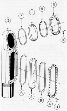
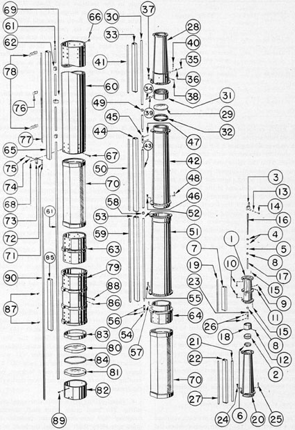
7C1. Description of the outer head, outer taper
section, and outer tube. Figure 7-1 shows the outer
head, head window and range window assemblies.
All bubble numbers in Sections 7C1, 2, and 4,
refer to Figure 7-1 unless otherwise specified.
Ill. No.
Drawing Number
Num- ber Re- quired
Nomenclature
1
P-1475-1
1
Head window
2
P-1475-2
1
Range window
3
P-1480-1
1
Outer head
4
P-1481-1
1
Range window bezel frame
5
P-1481-2
1
Head window bezel frame
6
P-1481-3
1
Range window seat rubber gasket
7
P-1481-4
1
Head window seat rubber gasket
8
P-1481-5
1
Range window bezel frame rubber gasket
9
P-1481-6
1
Head window bezel frame rubber gasket
10
P-1506-16
14
Head window bezel frame lockscrews
11
P-1506-17
28
Range window bezel frame lockscrews
a. Outer head. The outer head (3) is made
of solid forged corrosion-resisting steel. It serves
as a covering for the skeleton head assembly
(Figure 7-5) and is assembled to the upper part
of the outer taper section (1, Figure 7-2).
The lower part of the outer head has a tapered
alignment support section with a straight
threaded periphery of 32 threads per inch
preceding it, which fits into a similar internal
tapered alignment support section and threaded
section in the upper part of the outer taper
section.
A mixture of litharge and glycerin is used over
the threads to maintain an internal gas and
external water seal, thus establishing a permanent joint between the outer, head and upper
part of the outer taper section.
The outer head flange is machined at an
angle of 17 degrees 30', with a recess seat to carry a
sealing rubber gasket (7) under a head window
(1). Above the head window an additional
sealing rubber gasket (9) adheres directly to
the beveled edge of the head window and
beveled seat in the head window bezel frame (5).
Figure 7-1. Outer head, head window, and range
window assemblies.
The outer head flange has 14 proportionately
spaced tapped holes for retaining the head
window bezel frame (5) by means of 14 lockscrews (10) which are inserted in countersunk
clearance holes in the head window bezel frame
and screwed into tapped holes in the outer
head flange.
Below the head window flange provision, a
machined range window flange and recess seat
is provided to carry a sealing rubber gasket
(6) under a range window (2). Above the range
window an additional sealing rubber gasket (8)
adheres directly to the beveled edge of the range
window and the beveled seat in the range window
bezel frame (4).
373
The range window flange provision has 28
proportionately spaced tapped holes for retaining
the range window bezel frame (4) by means
of 28 lockscrews (11) which are inserted in
countersunk clearance holes in the range window
bezel frame and screwed into tapped holes in
the range window flange.
The interior surface of the outer head is
provided with ample clearance for light transmission, prism tilt mechanism, and change of
power mechanism of the skeleton head and
antenna array assemblies for transmission of
the ultra-high frequencies of the electronic
device.
b. Head window bezel frame and head
window. 1. Head window bezel frame.
The head window bezel frame (5) is made of
phosphor bronze and is 5 7/32 inches in length.
Its lower face has a machined irregular recess
to fit on the head window (1) which has a 45 degrees
angle. The 45 degrees angle of the beveled recess
accommodates the head window bezel frame
rubber gasket (9), which compresses to the
angle of the head window (1) to form an air
tight joint.
The outer flange of this bezel frame has 14
proportionately spaced countersunk clearance
holes to accommodate the lockscrews (3). These
lockscrews extend beyond the above countersunk clearance holes and are screwed into tapped
holes in the outer head flange for the head
window assembly. The upper side face of the
bezel frame follows the same pattern as its
sides, while the lower side is beveled inward at
an angle of 17 degrees 30', thus providing ample
clearance for the range window, bezel frame (4)
directly below it.
The inner irregular circumference of the bezel
frame is beveled at an angle of 45 degrees away from
the line of contact with the glass to increase the
effect of wind in clearing drops of water from
the glass and to reduce the lodgement of water
and deposits of salt by evaporation oil the glass
near the inner circumference.
2. Head window. The head window (1)
is made of one crown optical glass element
with parallel surfaces, and rests in the recess
seat in the outer head on a seat gasket (7).
It is molded with a 45 degrees angle edge to which a
bezel frame rubber gasket (9) is applied. It
provides a means of sealing without obstructing
the entering light rays, and offers a transparent
medium through which light is transmitted.
c. Range window bezel frame and range
window. 1. Range window bezel frame.
The range window bezel frame (4) is made of
phosphor bronze and is 9.675 inches in length.
Its lower face has a machined irregular recess
to fit on the range window (2) which has a 45 degrees
angle. The 45 degrees angle of the beveled recess
accommodates the range window bezel frame
rubber gasket (8), which compresses to the
angle of the range window (2) to form an air
tight joint.
The outer flange of this bezel frame has 28
proportionately spaced countersunk clearance
holes to accommodate lockscrews (11). These
lockscrews extend beyond the above countersunk
clearance holes, and are screwed into tapped
holes in the outer head flange for the range
window assembly. The upper and lower side
faces follow the same pattern as its sides,
with all corners rounded.
The inner irregular circumference of the bezel
frame is beveled at an angle of 45 degrees away from
the line of contact with the glass, for the same
purpose as that described for the head window
bezel frame (5).
2. Range window. The range window (2)
is made of No. 774 Corning glass with parallel
surfaces. It is 0.630 inch thick with an accuracy
of 0.002 inch, and fits into the recess seat in
the range window assembly flange of the outer
head on a seat gasket (6). It is molded with a
45 degrees angle edge to which a bezel frame rubber
gasket (8) is applied. In some periscopes this
window has been left in an unpolished condition
to reduce reflection from sunlight.
The distance between the inner face of the
range window and the antenna array must have
a clearance of 0.612 inch plus or minus 0.031
inch. Any substitution for No. 774 Corning
glass in the window will radically change performance, as likewise will any chipping of the
silvered or copper plated surfaces.
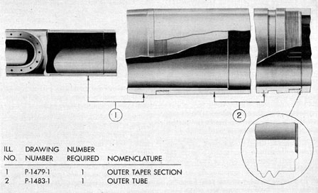
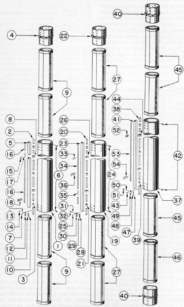
d. Outer taper section. The outer taper
section (1, Figure 7-2) is made of solid forged
corrosion resisting steel material, and has an
over-all length of 5 feet 9.500 inches. It forms
374
Figure 7-2. Outer taper section and outer tube.
the outer body to protect the five reduced tube
sections. The assembly of its upper part of the
outer head is described in Section 7c1-a on page
373.
The lower part of the outer taper section is
provided with a tapered alignment support
section with a straight threaded periphery of 12
threads per inch preceding it which fits into a
similar internal tapered alignment support
section and threaded section in the upper part
of the outer tube (2). A mixture of litharge and
glycerine is used over the threads to maintain
an internal gas and external water seal, thus
establishing a permanent joint between the
outer taper section and the outer tube.
The inside diameter of the outer taper section
does not vary from its calculated diameter at
any point by plus 0.015 inch or minus 0.000 inch;
and the bore of the taper is concentric within
0.005-inch finished machined.
e. Outer tube. The outer tube (2, Figure 7-2)
is made of solid forged corrosion-resisting steel
and has an over-all length of 29 feet 3.375 inches.
It forms the outer body for the inner tube
sections as shown in Figure 7-3. The upper part
has an internal alignment support and threaded
section, to receive the lower part of the outer
taper section as a permanent joint.
The interior of the outer tube is bored, with
the eccentric bearing flanges of the inner tube
sections and their couplings having a sliding
clearance. The external diameter, azimuth
scale lines, and numerals are similar to the Type
II periscope outer tube, except for the fact that
the numerals start from 35 feet. The milled
inside keyway, undercut groove, and ridge
detail are also similar to the Type II periscope
outer tube. The external threaded periphery has
16 right-hand threads per inch, whereas the
Types II and III periscopes have 12 threads
per inch.
7C2. Disassembly of the head and range window
assemblies. The head window and range window
assemblies are disassembled in the following
manner:
1. Unscrew each of the 14 lockscrews (10)
evenly, with several threads of each lockscrew
remaining in the outer head flange face for the
head window assembly (3).
375
2. Unscrew each of the 28 lockscrews (11)
evenly, with several threads of each lockscrew
remaining in the outer head flange face for the
range window assembly (3).
3. In order to break the seal of the head
window (1) and range window (2) it is necessary
to apply an internal nitrogen pressure of 15 to
30 pounds in the instrument. To apply an
internal nitrogen pressure requires the blanking
off of the lower part of the outer tube (2, Figure
7-2) with a suitable jig and fittings for a pressure
gage and a charging line.
4. After both the head window (1) and range
window (2) are broken free, release the internal
gas pressure, and remove the jig.
5. Remove the 14 lockscrews (10), unscrewing them from the tapped holes in the
outer head flange face for the head window
assembly (3).
6. Remove the head window bezel frame (5),
lifting it away from the flange face of the outer
head.
7. Remove the head window (1) and the
head window bezel frame rubber gasket (9).
The head window may stick to the head window
bezel frame rubber gasket (9) and the bezel
frame (5). Remove the head window bezel
frame rubber gasket (9) and destroy it.
8. Remove the bead Window seat rubber
gasket (7) from the recess seat in the outer
head (3) and destroy it.
9. Remove the 28 lockscrews (11), unscrewing them from the tapped holes in the outer
head flange face for the range window assembly
(3).
10. Remove the range window bezel frame
(4), lifting it away from the flange face of the
outer head (3).
11. Remove the range window (2) and the
range window bezel frame rubber gasket (8).
The range window may stick to the range window
bezel frame rubber gasket (8) and the bezel
frame (4). Remove the range window bezel
frame rubber gasket (8) and destroy it.
12. Remove the range window seat rubber
gasket (6) from the recess seat in the outer
head (3) and destroy it.
7C3. Cleaning of the outer head, outer taper section, and outer tube. The outer head, outer taper
section, and outer tube are cleaned in the
following manner:
1. They should be cleaned after flooding
with the use of various sized circular wire
brushes and turkish toweling to remove salt
deposits. They should then be blown out with
filtered air.
2. Under normal conditions, turkish toweling
should be used to clean out the outer head,
outer taper section, and outer tube.
3. Place a canvas boot over both the outer
head and the lower end of the outer tube to
prevent any foreign matter from entering the
cleaned outer tube, outer taper section, and
outer head.
7C4. Reassembly of the head and range window
assemblies. The head and range window assemblies are reassembled in the following
manner.
1. Scrape the seat of the outer head for the
head window if necessary, to give a true bearing
surface. The head window (1) must be marked
in the position its seat is scraped so that it cannot
be turned end for end.
2. Place the new head window seat rubber
gasket (7) of crude rubber and specified factory
drawing dimensions for its insertion in the head
window seat in the outer head (3).
3. The beveled seat in the head window bezel
frame (5) should be scraped if necessary, to
provide a true bearing surface in conjunction
with, the beveled edge of the head window (1).
4. Clean the liner surface of the head window
(1) with clean lens tissue and use a small air
bulb to blow off any surface dust.
5. Place the head window (1) in the head
window seat in the outer head (3) on the head
window seat rubber gasket (7).
6. The head window bezel frame rubber
gasket (9) should be approximately 1/8 inch
larger than the head window outer irregular
circumference, except to comply to factory
drawing dimensions as to thickness. It is placed
in the head window bezel frame (5) in one
solid piece. Punch a small hole in the center of
376
the rubber gasket to allow the tapped air to
escape.
7. Place the head window bezel frame (5)
with the head window bezel frame rubber
gasket (9) on the head window (1). Insert the
four lockscrews (10) in countersunk clearance
holes in the bezel frame and screw them in the
tapped holes in the flange face of the outer
head. Each lockscrew is screwed down flush
with the head window bezel frame.
8. A flat wooden block 1 inch thick and
slightly smaller than the inner circumference
of the head window bezel frame (5) is placed
on the head window bezel frame rubber gasket
(9). Place a C-clamp over the wooden block
and the outer head to flatten the raised center
portion of the rubber gasket. Use a wooden
wedge on the opposite side of the outer head to
tighten the C-clamp evenly. The flattening
of the rubber gasket forces its outer edges
to adhere to the inner beveled walls in the head
window bezel frame (5), and utilizes the entire
area of the beveled surface in the bezel frame
to maintain the seal.
9. Lubricate the 14 lockscrews (10) lightly
with a medium grease before insertion and
tighten them evenly. Each lockscrew is taken
down equally in a series of all around adjustments, and a feeler gage is used as a check around
the head window bezel frame (5). The bezel
frame is tightened down to a snug setting
of all lockscrews about 0.040. inch. It is desirable
to maintain a .0.007-inch to 0.010-inch clearance
between the bottom face of the head window
bezel frame (5) and the flange face of the outer
head (3). Remove the C-clamp and wooden
block.
10. It is desirable to wet the head window
bezel frame rubber gasket (9) thereby offering
a lubricant for a brass knife edge when cutting
the crude rubber gasket around the inner
irregular circumference of the head window
bezel frame (5). The brass knife edge will not
scratch the head window surface.
11. Scrape the range window seat in the outer
head (3), if necessary, to give a true bearing
surface. The range window (2) must be marked
in the position its seat is scraped so that it
cannot be turned end for end.
12. Insert the new range window seat rubber
gasket (6) of crude or synthetic rubber of
specified factory drawing dimensions in the
range window seat in the outer head (3).
13. The beveled seat in the range window
bezel frame (4) should be scraped if necessary,
to provide a true bearing surface in conjunction
with the beveled edge on the range window (2).
14. Clean the inner surface of the range
window (2) in the same manner as described
for the head window (1) under Step 4 of this
section. The range window should be silvered
and copper plated on three surfaces; namely,
the beveled edge, the outer irregular circumference, and the bottom face in contact with the
seat gasket. The silvered and copper plating
of the range window wherever it contacts the
metal seat of the outer head eliminates the
possibility of a fluctuation in the standing wave
ratio of the antenna system, should water
become lodged between the window and its
seat in the outer head. However, its most
important function is to insure that there is no
RF leakage through the crack between the
range window bezel frame (4) and the range
window seat in the outer head (3).
15. Place the range window (2) in the range
window seat in the outer head (5) on the range
window seat rubber gasket (6).
16. The range window bezel frame rubber gasket (8) should be of specified factory drawing
dimensions as to thickness. It should be approximately 1 3/16 inch larger than the range window
outer irregular circumference. It is placed in the
range window bezel frame (4) in one solid piece.
Punch two 3/16-inch holes in the rubber gasket
to allow trapped air to escape.
17. Place the range window bezel frame (4)
with the range window bezel frame rubber
gasket (8) on the range window (2). Insert
six lockscrews (11) in countersunk clearance
holes in the bezel frame and screw them in the
tapped holes in the flange of the outer head.
Each lockscrew is screwed down flush with
the range window bezel frame.
18. A flat wooden block 1 inch thick and
slightly smaller than the inner irregular circumference of the range window bezel frame (4)
is placed on the range window bezel rubber
377
gasket (8). A C-clamp is placed over the wooden
block and the outer head to flatten the raised
center portion of the rubber gasket. The flattening of the rubber gasket confines its, outer edges
to adhere to the inner beveled walls in the range
window bezel frame, and utilizes the entire
area of the beveled surface in the range window
bezel frame (4) to maintain the seal.
19. Lubricate the threads of the 28 lockscrews
(11) lightly with a medium grease before insertion and tighten them evenly. Each lockscrew
is taken down in a series of all around adjustments, and a feeler gage is used as a check
around the range window bezel frame (4) to
determine whether it is tightened down evenly.
The range window bezel frame is tightened down
to a snug setting of all lockscrews about 0.030
to 0.035 inch with crude rubber. With a synthetic rubber gasket, the bezel frame is tightened
from an even all around snug setting of all
lockscrews to about 0.025 to 0.027-inch. After
a hydraulic and temperature test, this type of
rubber gasket will require a further tightening
of all lockscrews (11) about 3/4 to a full turn.
However, this condition does not exist with
crude rubber.
20. It is not desirable to wet the range window
rubber gasket while using synthetic rubber
material; however, it is desirable to wet the
crude rubber gasket. This offers a lubricant
for a brass knife edge when cutting the rubber
gasket around the inner irregular circumference
of the range window bezel frame (4). The brass
blade will not scratch the range window surface.
21. If the outer surface of the range window
has been polished and the window has not been
painted, a thin coat of black aircraft enamel,
type AL-E-7, should be applied by spraying.
This is to reduce specular reflection of the sun
from the window. IMPORTANT: Use only
the paint designated. Any other paint will
seriously impair the efficiency of attached
electronic apparatus.
7C5. Inner tube assemblies.Figure 7-3 shows the
inner tube of the periscope divided into telescope
systems. Each telescope system is made up of
assemblies as follows:
A. Galilean telescope system.
1. Skeleton head assembly.
2. Antenna array and taper section assembly,
B. Upper main telescope system.
1. Part I. First, second, third, fourth,
and fifth reduced tube sections and
seventh and eighth inner tube sections.
2. Part II. Fourth, fifth, and sixth inner
tube sections.
C. Lower main telescope system.
1. Part I. First, second, and third inner
tube sections.
2. Part II. Eyepiece skeleton assembly.
a. Part II.
Eyepiece box and miscellaneous assemblies.
b. " "
Four packing gland assemblies.
c. " "
Eyepiece window assembly.
d. " "
Bottom plug assembly.
e. " "
Focusing knob assembly.
f. " "
Rayfilter housing and plate assembly.
g. " "
Rayfilter, eyebuffer, blinder, and stowage case assemblies.
h. " "
Variable density polaroid filter assembly.
i. " "
Training handle assemblies.
j. " "
Hoisting yoke assembly (electric and hydraulic).
D. SEPARATION OF THE THREE TELESCOPE SYSTEMS
7D1. Removal of external projections, miscellaneous assemblies, and the eyepiece box. This
procedure is performed in the following manner:
1. Remove the 12 bottom plug window housing lockscrews (7, Figure 7-17) from the bottom
face in the bottom plug housing (1). These
lockscrews are unscrewed from tapped holes in
the counterbored seat in the eyepiece box base
(11, Figure 7-12).
2. Attach a special square plate jig (Figure
7-4) to the face of the bottom plug clamp ring
(2, Figure 7-17) with coinciding clearance
378
holes to match four 8-32 tapped holes. Insert
the four special 8-32 screws into the tapped
holes in the bottom plug clamp ring, securing
the special square plate jig.
3. Tap the handle part of the special square
plate jig, thereby loosening and pulling out
the bottom plug assembly from the counterbored
recess seat in the eyepiece box base. Remove the
bottom plug housing rubber gasket (3, Figure
7-17), and destroy it.
4. Remove the 10 pressure gage assembly
lockscrews (18, Figure 7-12), removing the
pressure gage assembly (10).
5. Remove the four short and eight long
eyepiece window frame lockscrews (2, and 3,
Figure 4-38) removing the eyepiece window
assembly.
6. Remove the eyepiece lens mount (78,
Figure 7-11) with the eyepiece lens (33) eyepiece
lens clamp ring (15), and its lockscrew (70)
from the eyepiece prism front retaining plate
(22).
7. Remove the six lockscrews (10, Figure
7-15) from the left training handle stuffing
box body (7). Place the special packing gland
wrench on the square section of the training
handle actuating shaft (8), using a slight
sideward thrust to remove the left training
handle packing gland assembly. Remove the
training handle stuffing box rubber gasket (3).
8. Remove the six 1ockscrews (10, Figure
7-16) from the right training handle stuffing
box body (7). Remove the right training handle
packing gland assembly in the same manner as
noted in Step 7 for the left training handle
packing gland assembly.
9. Remove the six lockscrews (10, Figure
7-14) from the eyepiece drive stuffing box
body (8). Remove the eyepiece drive packing
gland assembly in the same manner as noted
in Step 7 for the left training handle packing,
gland assembly. Remove the eyepiece drive
stuffing box body rubber gasket (3).
10. Remove the four rayfilter drive stuffing
box body lockscrews (11, Figure 7-13) from the
rayfilter drive stuffing box body (6). Remove the
rayfilter drive actuating gear (9) from the square
section of the rayfilter drive actuating shaft (8).
Place a pair of parallel pliers on the square
section of the rayfilter drive actuating shaft (8)
using a slight sideward thrust to remove the
rayfilter drive packing gland assembly. Remove
the rayfilter drive stuffing box body rubber
gasket (3).
11. Remove the seven lockscrews (40, Figure
7-11) from the large flange of the eyepiece
skeleton (42). These lockscrews are unscrewed
from tapped holes in the upper face of the
eyepiece box.
12. Remove the eyepiece box (11, Figure
7-12) from the eyepiece skeleton (42, Figure
7-11), sliding it off the eyepiece skeleton.
7D2. Removal of the waveguide and air line
sections. This procedure is performed in the
following manner:
1. Remove the two antenna array end plate
bracket lockscrews (49, Figure 7-5) from the
antenna array end plate bracket (64). These
lockscrews are unscrewed from tapped holes
in the front face of the skeleton head (10).
2. Remove the two antenna array taper
section bracket lockscrews (54) from the antenna
array taper section bracket (66). These lock
Figure 7-4. Bottom plug assembly removal jig.
379
screws are unscrewed from tapped holes in the
front face of the skeleton head. Remove the
antenna array taper section bracket.
3. Release the two waveguide clamp plate
adjustment screw lock nuts (75, Figure 7-6)
and two waveguide clamp plate adjustment
screws (74) to release the tension of the wave
guide clamp plates (71) from the waveguide
section continuation (65). These adjustment
screws extend into tapped holes in the waveguide clamp bracket (73) attached to the eighth
inner tube section lower end (60).
4. Release the four waveguide clamp plate
adjustment screw lock nuts (14, Figure 7-7)
and the four waveguide clamp plate adjustment
screws (13). This releases the tension of the two
waveguide clamp plates (10) from the waveguide
section continuation (5). These adjustment
screws extend into two tapped holes in each
waveguide clamp bracket (12) attached to the
sixth inner tube section (1) upper and lower
ends.
5. Follow the procedure stated in Step 4,
for the fifth inner tube section (19). Two waveguide clamp brackets, (30) are located at its
upper and lower ends. These consist of the four
waveguide clamp plate adjustment screw locknuts (32), four waveguide clamp plate adjustment screws (31), and the, two waveguide clamp
plates (28) for the waveguide section continuation (23).
6. Follow the procedure stated in Step 4
for the fourth inner tube section (37). Two
waveguide clamp brackets (49) are located at
its up and lower ends. These consist of the
four waveguide clamp plate adjustment screw
locknuts, (51), four waveguide clamp plate
adjustment screws (50), and the two waveguide
clamp plates (47) for the waveguide section
continuation (41)
7. Follows the procedure stated in Step 4
for the second inner tube section (14, Figure
7-10) waveguide clamp bracket (25), located at
its upper end only. This consists of the two
waveguide clamp plate adjustment screw lock
nuts (27), two waveguide clamp plate adjustment
screws (26), and the two waveguide clamp plate
(23) for the waveguide section continuation
(19).
8. Remove the antenna array, taper section,
and waveguide to an isolated place where
damage is not likely to occur.
9. Remove the waveguide clamp plate (71,
Figure 7-6) and its pins (72) from the waveguide
clamp bracket (73) of the eighth inner tube section (60) located at its lower end.
10. Remove the two waveguide clamp plates
(10, Figure 7-7) and their pins (11) from the
two waveguide clamp brackets (12) of the sixth
inner tube section (1) located at its upper
and lower ends.
11. Remove the two waveguide clamp plates
(28) and their pins (29) from the two waveguide
clamp brackets (30) of the fifth inner tube
section (19) located at its upper and lower
ends.
12. Remove the two waveguide clamp plates
(47) and their pins (48) from the waveguide
clamp brackets (49) of the fourth inner tube
section (37) located at its upper and lower ends.
13. Remove the waveguide clamp plate (23,
Figure 7-10) and its pins (24) from the waveguide
clamp bracket (25) of the second inner tube
section (14), located at its upper end only.
14. Slide the lower air line section continuations (13, 29, and 39) with the soldered air
line coupling (40), through a clearance hole in
and below the bottom face of the eyepiece
skeleton large shoulder flange. It is carried
downward sufficiently to break the air line
coupling (35, Figure 7-7) joint with the center
air line section continuation (34). After breaking
the air line coupling joint, the lower air line
section I(34) is slid upward and carried out at the
disconnection point which is located in the lower
part of the fifth inner tube section (19). It is
carried out of the eyepiece skeleton large
shoulder flange, through a clearance provision
in the counterweight half (37, Figure 7-11).
It is further carried through one soldered air
line strap (28, Figure 7-10) located on the second
inner tube section (14), four soldered air line
straps (52, Figure 7-7) located on the fourth
inner tube section (37), and one soldered air
line strap (33) located on the fifth inner tube
section (19).
15. Remove the center air line section (16)
and its continuation (34) with a soldered air
380
line coupling (17) at its upper end and another
air line coupling (35) at its lower end. Slide the
center air line section and its continuation
downward out of three soldered air line straps
(15) of the sixth inner tube section (1) and three
soldered air line straps (33) of the fifth inner
tube section (19). The center air line section
disconnection point is located at the lower part
of the fifth inner tube section.
16. Remove the upper air line section (19,
Figure 7-6) and its continuations (27, 41, 50,
59, 77, 90, and 16, Figure 7-7) from the skeleton
head (20, Figure 7-5), sliding it downward for
its disconnection from the skeleton head. It is
carried out of clearance holes in flanges of the
reduced tube sections and the reducing coupling.
It is further carried out of two soldered air line
straps (76, Figure 7-6) on the eighth inner tube
section (60) and one soldered air line strap (15,
Figure 7-7), on the sixth inner tube section (1).
The upper air line section disconnection point is
located at the upper part of the sixth inner tube
section.
7D3. Separation of the Galilean telescope system
and fifth reduced tube section. This procedure is
performed in the following manner:
1. Separate the Galilean telescope system
which is located in the skeleton head assembly
(Figure 7-5) from the upper flange of the fifth
reduced tube section (I, Figure 7-6) in the
following manner:
2. Remove the three lockscrews (42, Figure
7-5) from the left cube shifting rack (36),
removing the upper end of left power shifting
wire tape (35, Figure 7-11). Replace the clamp
block (26, Figure 7-5) on the left tape spacer
(27) and insert the lockscrews (42), screwing
them into the tapped holes in the left cube
shifting rack.
3. Remove the three lockscrews (43) from
the right cube shifting rack (34), removing the
upper end of the right power shifting wire tape
(35, Figure 7-11). Replace the clamp block (26,
Figure 7-5) on the right tape spacer (28) and
insert the lockscrew (43) screwing them into
the tapped holes in the right cube shifting rack.
4. Release the shifting wire clamp nuts (3,
Figure 7-11) of both shifting wire spindle
assemblies of the eyepiece skeleton assembly.
Pull upward and out on both phosphor-bronze
wire extensions from the shifting wire spindle
assemblies. Pull both lengths of the power
shifting wire tape from various soldered tape
straps on the inner tube sections. Roll up each
power shifting tape separately in a 15-inch
circle, and secure together at three equal places
with friction tape.
5. Elevate the head prism (1, Figure 7-5)
to full elevation, which places the quadruple
screw follower (3, Figure 7-6) in a suitable
position, so that the head prism actuating rack
(65, Figure 7-5) with its inserted dowel pins
(56) has sufficient clearance for its removal
from the quadruple screw follower (3, Figure
7-6). Check the position of the quadruple
screw follower (3) on the quadruple screw shaft
(16) so that it will be replaced in this identical
position for reassembly. Remove the three
lockscrews (41, Figure 7-5) from the head prism
actuating rack (65). These lockscrews ate unscrewed from tapped holes in the quadruple
screw follower (3, Figure 7-6).
6. Support the skeleton head assembly
(Figure 7-5), while removing the six lockscrews
(10, Figure 7-6) from the upper flange of the
fifth reduced tube section (1). These lockscrews
are unscrewed from tapped holes in the base of
the skeleton head.
7. Remove the skeleton head assembly
(Figure 7-5) from the upper flange of the fifth
reduced tube section (1, Figure 7-6). As the
skeleton head reamed alignment dowel pin
hole clears the alignment dowel pin (15) projection of the fifth reduced tube section, the
head prism is shifted to full depression. This is
accomplished in fact, by having the head prism
actuating rack (65, Figure 7-5) and dowel pins
(56) engaged in the reamed holes in the quadruple screw follower (3, Figure 7-6). It is necessary to force the head prism actuating rack
with its dowel pins free of the quadruple screw
follower reamed holes (3). The skeleton head
assembly is now free for removal from the upper
flange of the fifth reduced tube section. Remove
the skeleton head assembly from the fifth reduced
tube section and place it to one side to prevent
it from becoming damaged.
8. It is necessary to remove the skeleton head
from the fifth reduced tube section, and the fifth
381
reduced tube section from the fourth, to provide
sufficient clearance for disassembly of the head
prism drive shaft sections and their universal
couplings.
9. Remove the head prism drive shaft
universal coupling taper pin (26) from the
lower part of the head prism drive universal
coupling (23) and the head prism drive shaft
section (21) of the fourth reduced tube section
(20).
10. Separate the fifth reduced tube section
lower flange (1) from the fourth reduced tube
section upper flange (20) by removing the six
lockscrews (10) from the lower flange of the
fifth reduced tube section (1). Unscrew these
lockscrews from tapped holes in the upper
flange of the fourth reduced tube section. The
lower part of the head prism drive shaft universal
coupling (23) slides off the undercut part of the
head prism drive shaft section (21) as the fifth
reduced tube section is removed. Remove the
assembled fifth reduced tube section from the
fourth reduced tube section.
7D4. Removal of the head prism drive shaft sections
and their universal couplings. This procedure is
performed in the following manner:
1. Remove the head prism drive shaft universal coupling taper pin (56, Figure 7-6),
from the lower part of the head prism drive
shaft universal coupling (54) of the first inner
tube section (51) and the head prism drive shaft
section (61) of the eighth inner tube section (60).
2. Remove the assembled head prism drive
shaft, consisting of the head prism drive shaft
section (21) and its shaft continuation (30) with
an attached spherical bushing (49), head prism
drive shaft universal coupling (45), head prism
drive shaft section (43) with an attached spherical
bushing (58), its shaft continuation (52), and the
attached head prism drive shaft universal coupling (54), by carrying the above assembly upward. The upward movement of this assembly
clears the stub section of the head prism drive
shaft section (61) from the lower part of the head
prism drive shaft universal coupling (54) at
the lower end of the first reduced tube section
(51). The assembly is then carried downward
out of the clearance holes in the fourth, third,
second, and first reduced tube section flanges
at the disconnection point located in the lower
part of the first reduced tube section (51).
3. Remove the head prism drive shaft universal taper pin (36, Figure 7-10) from the upper
part of the head prism drive universal coupling
(34) and the stub section of the head prism
drive shaft section continuation (15) and
slide this shaft continuation upward sufficiently
to clear the coupling.
4. Remove the head prism drive shaft section
(33) and its continuation (48, Figure 7-11),
sliding it upward to free it from the upper part
of the head prism drive shaft universal coupling
(59), carrying with it the inserted woodruff
key (46). Check the position of the coupling
for proper reassembly. Remove the shaft from
the disconnection point located at the upper
end of the first inner tube section (31, Figure
7-10) sliding it out of the elongated holes in
the large and small flanges of the eyepiece
skeleton and the clearance holes in the first
inner tube section lower flange, carrying with
it the assembled head prism drive shaft universal
coupling (34).
5. Remove the head prism drive shaft section
continuations (15 and 4, Figure 7-10) and its
continuations (38, 20, and 2, Figure 7-7) of
the head prism drive shaft section (61, Figure
7-6), from its disconnection point located at the
upper part of the first inner tube section (31,
Figure 7-10). The shaft section is carried downward from various clearance holes in the coupling flanges, and the head prism drive shaft
guides which are attached to or part of the
second, third, fourth, fifth, sixth, seventh, and
eighth inner tube sections. The head prism
drive shaft rubber noise eliminators are removed
from the head prism drive shaft section and its
continuations W the eighth, sixth, fifth, fourth,
and second infer tube sections. This shaft and
its continuations can also be carried upward
from the first reduced tube section (51) by the
inverse method.
7D5. Separation of the upper telescope system
Part I from Part II. This consists of the first, second,
third, fourth, fifth reduced tube sections and
the seventh and eighth inner tube sections.
1. Remove the 24 lockscrews (87, Figure
7-6), from the lower part of the seventh inner
382
tube section (79) and the sixth inner tube section
upper end coupling (4, Figure 7-7). These
lockscrews are unscrewed from tapped holes
in the upper alignment support section of the
sixth inner tube section upper end coupling.
2. Remove the seventh inner tube section
(79, Figure 7-6), carrying it off the upper alignment support section of the sixth inner tube
section upper end coupling (4, Figure 7-7).
7D6. Separation of the upper telescope system
Part If from the lower telescope system Part I. This
consists of the fourth, fifth, and sixth inner
tube sections.
1. Remove the 24 lockscrews (10, Figure
7-10) from the upper part of the third inner
tube section (1) and the fourth inner tube
section lower end coupling (40, Figure 7-7).
These lockscrews are unscrewed from tapped
holes in the lower alignment support section
of the fourth inner tube section lower end
coupling.
2. Remove the fourth inner tube section
(37) carrying with it the fourth inner tube
section lower end coupling (40) from the upper
part of the third inner tube section (1, Figure
7-10).
7D7. Separation of the lower telescope system
Part I from the lower telescope system Part II, eyepiece skeleton assembly. This consists of the first,
second, and third inner tube sections.
1. Remove the seven lockscrews (40, Figure
7-11) from the small flange of the eyepiece
skeleton (42). These lockscrews are unscrewed
from tapped holes in the lower flange of the
first inner tube section (31, Figure 7-10).
Remove the eyepiece skeleton assembly (Figure
7-11) from the lower flange and alignment
support section of the first inner tube section
(31, Figure 7-10).
E. GALILEAN TELESCOPE SYSTEM
7E9. Description of the skeleton head and antenna
array assemblies as shown on Figure 7-5. All bubble
numbers in Sections 7E1, 2, and 3, refer to
Figure 7-5 unless otherwise specified.
Head prism actuating rack guide lockscrews (short)
53
P-1506-58
2
Head prism actuating rack guide lockscrews (long)
54
P-1506-60
2
Antenna array taper section bracket lockscrews
55
P-1506-10
1
Head prism mount lever taper pin
56
P-1506-116
2
Head prism actuating rack and quadruple screw, follower dowel pins
57
P-1506-117
2
Head prism mount and pivot shaft taper pins
58
P-1513-6
1
Head prism actuating rack guide
59
P-1513-7
1
Head prism actuating rack guide spacer
60
P-1516-1
1
2 Perforated antenna tubes
61
P-1516-2
2
Antenna tube taper pieces
62
P-1516-3
1
Antenna tube taper piece assembly
63
P-1516-4
1
Antenna array assembly
64
P-1516-5
1
Antenna array end plate bracket
65
P-1522-3
1
Head prism actuating rack
66
P-1522-5
1
Antenna array taper section bracket
67
P-1522-7
1
Head prism mount lever key
The following brief description covers the
skeleton head assembly:
a. Skeleton head frame. The skeleton
head frame (10) forms the necessary framework to carry the prism tilt mechanism, Galilean
telescope, and the change of power mechanism.
The prism tilt mechanism is composed of
numerous mechanical parts in the upper and
left side wall of the skeleton head to operate
one optical element, the head prism (1).
b. Head prism. The head prism (1) is a
right angle prism, made of dense flint optical
glass material. It is used to reflect the light rays
at right angles. The light rays enter from the
horizontal and are deflected downward into
the instrument. Light enters from 61 degrees elevation
to 26 degrees depression in low power, and 49 degrees elevation
to 14 degrees depression in high power.
c. Head prism mount. The head prism
mount (11) carries the head prism (1) with a
suitable clamping arrangement. Two head prism
side plates left and right (23 and 25) restrict
the head prism from sideward movement, and
are held to the head prism mount with three
lockscrews each (46). Each head, prism side
plate has a head prism shade wire link (22)
attached to it with a rivet (24). The opposite
end of each wire link is attached to the head
prism shade (20) in similar manner. Two pairs
of head prism mounting clamps left and right
(38 and 39) hold the head prism to its mount.
Each pair of mounting clamps is held to the head
prism mount with four lockscrews (44). The
head prism mount is held in the skeleton head
by means of a head prism mount pivot shaft
(37) which is secured with two taper pins (57).
The pivot shaft is secured in a bearing bracket
projection looted under and a part of the head
prism mount base. The pivot shaft rotates in
two head prism mount pivot shaft bushings
(29) inserted in opposite sides of the skeleton
head (10).
d. Head prism shade. The head prism
shade (20) by means of two wire links (22)
moves vertically with the head prism and
its mount by its insertion in opposite vertical
grooves in the inner side walls of the skeleton
head. It is carried with the head prism (1) and
its mount for all degrees of elevation and
384
Figure 7-5. Skeleton head and antenna array assemblies.
depression and shades the lower 90 degrees face of
the head prism when in, the elevated position,
thus preventing a double image.
e. Head, prism mount lever. The head
prism mount lever (12) is attached to the head
prism mount pivot shaft (37) with a key (67)
and a taper pin (55) to operate the pivot shaft
for the elevation and the depression of the head
prism (1).
f. Head prism actuating link. The head
prism actuating link (16) fork section attaches
to the head prism mount lever (12) by means
of a link connecting shaft (18) and is secured
with a lockscrew (48) at its upper part. The fork
section of the lower part is attached to a head
prism actuating rack (65) in similar manner.
The above actuating link forms a linkage
between the head prism mount lever and the
385
head prism actuating rack for actuation of
the head prism.
g. Head prism actuating rack. The head
prism actuating rack (65) is provided with two
integral stops which contact a cube bracket
(14) on each side, thus restricting the centerline
of sight to 45 degrees elevation and 10 degrees depression.
The lower part of this actuating rack is attached to a quadruple screw follower (3, Figure
7-6), by means of three lockscrews (41), and
its alignment is maintained with two dowel
pins (56). The actuating rack is attached to
the head prism actuating link (16), by means
of a link connecting shaft (18) inserted in the
reamed hole in the fork section of the actuating
link and the inserted bushing (17). It provides
a further linkage with the actuating link for
operation of the head prism mount lever (12).
h. Head prism actuating rack guide. The
head prism actuating rack guide (58) has a
recess slot to fit over the head prism actuating
rack (65) on a head prism actuating rack guide
spacer (59) and is secured to the skeleton head
frame with two short and long lockscrews (52
and 53). The actuating rack guide provides a
guidance for the head prism actuating rack (65).
i. Galilean eyepiece lens cube bracket.
The Galilean (eyepiece lens cube bracket (19)
has an integral pin projection, which serves as a
pivot for the Galilean eyepiece lens cube (4)
on the prism shift side. A stop is provided in its
inner face to allow the cube bracket to fit over
the head prism actuating link (16), thus providing a parallel guidance to the actuating link.
The cube bracket is secured the skeleton
head fame with two lockscrews (51).
j. Galilean objective lens cube bracket.
The Galilean objective lens cube bracket (14)
has an integral pin projection and serves as a
pivot for the Galilean objective lens cube (5)
on the prism shift side. A recess slot is provided
in its inner face to fit over the head prism
actuating rack (65). The cube bracket is secured
to the skeleton head frame with two lockscrews
(51) and provides a parallel guidance to the
head prism actuating rack. It also serves as a
stop in its upper and lower parts for the integral
stops of the head prism actuating rack for
elevation and depression of the head prism (1).
The Galilean telescope system is composed
of two lenses; namely, a negative Galilean
eyepiece lens doublet and a positive Galilean
objective lens doublet. It is used in reverse to
effect a low power magnification and increase
the true field of view.
k. Galilean eyepiece lens. The Galilean
eyepiece lens (2) is made of two optical elements.
It consists of a divergent meniscus flint element,
cemented to the equi-concave crown element,
forming a negative doublet. It is mounted in a
Galilean eyepiece lens mount (7) in similar
manner to the Type II and III periscope with
the threaded periphery of the mount moving
vertically in the internal threads in the Galilean
eyepiece lens mount housing (6). This vertical
movement provides a means for elimination of
parallax.
1. Galilean eyepiece lens mount housing.
The Galilean eyepiece lens mount housing
(6) is provided with an internal threaded section bore to carry the Galilean eyepiece lens
mount (7) and the Galilean eyepiece lens (2).
A lockscrew (50) inserted in a tapped hole in
this housing secures the Galilean eyepiece
lens mount after the parallax elimination.
The housing is attached to the Galilean eyepiece lens cube (4) with three lockscrews (9).
The housing flange has three equally spaced
holes. One hole is used as a pivot hole, while
the other two are elongated for collimation
adjustment.
m. Galilean eyepiece lens cube. The
Galilean eyepiece lens cube (4) provides a
means for holding the Galilean eyepiece lens
mount (7) and its housing (6). By means of
integral pin projections, a part of the cube
brackets (19 and 13) inserted in the reamed
hole axis of this cube, the eyepiece lens cube
can be rotated 90 degrees for either the IN or OUT
position. The pawl holder (30) engaged in
the V-grooves in the right side face of the cube,
by the tension of a reinforcing spring (33),
retains it in either the IN or OUT position. An
elongated slot in the right side face of the cube
receives an upper pin projection (68) assembled
in the right cube shifting rack (34) for its
actuation.
n. Galilean objective lens. The Galilean
objective lens (3) is made of two optical elements.
386
It consists of a double convex flint element
cemented to a double concave flint element
forming a positive objective doublet. It is
mounted in a shallow counterbored section
in the Galilean objective lens cube (5) and is
secured with a Galilean objective lens retainer
(8). The lens retainer is spot soldered to the
Galilean objective lens cube to prevent it from
unscrewing.
o. Galilean objective lens cube. The Galilean objective lens cube (5) provides a means
for holding the Galilean objective lens (3)
in a shallow counterbored section. The outer
shoulder has a threaded periphery to carry
the Galilean objective lens retainer (8). By
means of integral pin projections, a part of the
cube brackets (14 and 13) inserted in the reamed
hole axis in the cube, the objective lens cube can
be rotated 90 degrees for either the IN or OUT position. The pawl holder (30) engaged in the
V-grooves in the right side face of the cube
retains it in either the IN or OUT position
by the tension of the reinforcing spring (33).
An elongated slot in the right side face of the
cube receives a lower pin projection (68) assembled in the right cube shifting rack (34)
for its actuation.
The change of power mechanism is located
on the right side of the skeleton head frame.
p. Cube shifting racks. The tube shifting
racks right and left 36) operate in
vertical recess grooves in the right side wall
of the skeleton head. The right cube shifting
rack (34) has two assembled pin projections (68)
which extend through the two elongated slots
in the vertical recess groove in the right side
wall of the skeleton head. The pin projections
are riveted to the right cube shifting rack, and
after extending through the two elongated slots,
extend farther into the elongated slots in the
right side faces of the Galilean eyepiece lens
and the objective lens cubes (4 and 5). An
integral stop is provided on each rack to contact
the Galilean objective lens cube bracket (13)
at the IN and OUT positions.
q. Power shifts gear. The power shift gear
(35) fits between the gear teeth cut in the right
and left cube shifting racks (34 and 35). The
power shift gear carries the right cube shifting
rack (34) to the upward position as the left cube
shifting rack (36) is carried downward and vice
versa. It pivots on the integral pin projection
of the power shift gear bracket (15).
r. Power shift pawls. The two power shift
pawls (30) are attached to the pawl holders
(31) with two rivets each (32) and are secured
in a vertical recess groove in the side wall
of the skeleton head to the left of the left cube
shifting rack (36). Each pawl holder is secured
in the recess groove with two lockscrews (47).
The detent section of each pawl holder extends
into its individual axial slot located in this
vertical recess groove to engage in their respective V-grooves in each Galilean eyepiece lens
and objective lens cube (4 and 5). A reinforcing
spring (33) is placed over each power shift
pawl (30), and is secured into the center of the
recess groove with three lockscrews (47).
The reinforcing spring overlapping each power
shift pawl section of the pawl holder places a
constant tension on the power shift pawls, for
their retention in the V-grooves.
s. Galilean eyepiece and objective lens
cube brackets. The Galilean eyepiece and
objective lens cube brackets (power shift
side) (13) are of duplicate design. Each bracket
has an integral pin projection, which serves
as a pivot for the pivot hole axis in the Galilean
eyepiece lens and the objective lens cubes (4
and 5) on the power shift side. Both cube
brackets fit over the cube shifting racks (34
and 36) and power shift pawls and retaining
spring. These brackets are secured to the flat
section of the skeleton head frame with two
lockscrews each (40). The Galilean objective
lens cube bracket serves as a stop for the cube
shifting racks (34 and 36) for the IN and OUT
position of the cubes.
The Galilean telescope system in the IN
position has the Galilean eyepiece and objective
lenses located at the upper part of their respective cubes. When in the OUT position, both
lenses are located in the rear of the skeleton
head frame.
The skeleton head assembly is attached to the
upper flange of the fifth reduced tube section
(1, Figure 7-6) by means of a shallow counterbored alignment support section fitting on the
alignment support section shoulder of the fifth
reduced tube section upper flange.
387
The skeleton head lower face is provided with
six tapped holes, one reamed dowel pin hole,
and an air line clearance hole. The reamed dowel
pin hole receives the dowel pin (15) secured in
the upper flange face of the fifth reduced tube
section to reestablish the factory alignment
upon disassembly. The six tapped holes receive
the lockscrews (10) inserted in clearance holes
in the fifth reduced tube section upper flange
for the securement of the skeleton head assembly.
The air line clearance hole coincides with a
clearance hole in the upper flange of the fifth
reduced tube section for the insertion of the
upper end of the upper air line section (19) for
the introduction of nitrogen.
t. Taper section. The taper section (62)
consists of two sections of waveguide tubing
(61) which are silver soldered together.
u. Antenna array assembly. The antenna
array assembly (63) consists of three parts:
1) end plate bracket (64), 2) perforated antenna
tubes (60), and 3) taper section assembly
(62). All three parts are silver soldered together
to form the antenna array assembly. The
taper section (62) is silver soldered to the
waveguide section (7, Figure 7-6). This assembly is secured to the skeleton head in a recess
seat of similar construction milled in the front
face of the skeleton head. It is secured as before
mentioned in its upper and lower parts.
1. Antenna array end plate bracket. The
antenna array end plate bracket (64) consists
of a rectangular plate with a small rectangular
projecting section. The plate section is silver
soldered to the upper end of the assembled
perforated antenna tubes (60). The rectangular
projector extending upward is provided with
two clearance holes for the insertion of the
lockscrews (49). These lockscrews, when inserted, extend into tapped holes in the antenna
array milled recess in the skeleton head for
the securement of the upper end of the antenna
array (63).
2. Perforated antenna tubes. A The two
perforated sections of waveguide tubing (60)
consist of two sections of waveguide tubing
with six staggered rectangular perforations
located in each outer face. Both sections are
silver soldered together.
3. Antenna array taper section bracket.
The antenna array taper section bracket (64)
is bent to conform to the taper section assembly
(62) for the securement of the lower end of the
antenna array (63) to the skeleton head. This
bracket has opposite overlapping sections, each
provided with a clearance hole for the insertion
of lockscrews (54). These lockscrews extend
into tapped holes in the front face of the skeleton
head.
7E2. Disassembly. The skeleton head assembly
is disassembled in the following manner:
1. Move the cube shifting racks (34 and
36), shifting the Galilean telescope system
in the OUT position. This allows the Galilean
eyepiece lens (2), its mount (7), and the Galilean
eyepiece lens mount housing (6) to be removed.
Remove the three lockscrews (9) from the
flange section of the Galilean eyepiece lens
mount housing (6). These lockscrews are
unscrewed from the tapped holes in the face of
the Galilean eyepiece lens cube (4). Scrape off
the spot solder from the Galilean objective lens
retainer (8) and the Galilean objective lens
cube (5). Remove the Galilean objective lens (3).
Release the lockscrews (50) and remove the
Galilean eyepiece dens (2) and its mount (7),
unscrewing it from the Galilean eyepiece lens
mount housing (6). Wrap the Galilean eyepiece
lens, its mount, and the Galilean objective lens
separately in clean lens tissue and place to
one side to prevent scratches and breakage.
2. Remove the two short and long head prism
actuating rack guide lockscrews (52 and 53).
Remove the head prism actuating rack guide
(58) and the head prism actuating rack guide
spacer (59).
3. Remove the two Galilean objective lens
cube bracket lockscrews (prism shift side)
(51) from the } Galilean objective lens cube
bracket (prism shift side) (14). Remove the
Galilean objective lens cube bracket (prism
shift side) (14).
4. Remove the two Galilean eyepiece lens
cube bracket lockscrews (prism shift side) (51).
Remove the Galilean eyepiece lens cube bracket
(prism shift side) (19).
5. Shift the head prism (1) to full elevation,
in order to insert a drift punch from the rear
388
side of the skeleton head (10). Drive out both
the head prism mount and the head prism mount
pivot shaft taper pins (57).
6. Shift the head prism to full depression
and release the two head prism mount pivot
shaft lockscrews (45).
7. Remove the complete assembly of the
prism tilt mechanism which consists of the
following from the skeleton head: head prism
mount lever (12), head prism actuating link
(16), link connecting shaft bushing (17), two
link connecting shafts (18), head prism mount
pivot shaft (37), two link connecting shaft
lockscrews (48), head prism mount lever taper
pin (55), head prism actuating rack (65), and
the head prism mount lever key (67). The head
prism mount pivot shaft (37) is carried out of
the integral bearing brackets of the head prism
mount and the opposite head prism mount pivot
shaft bushings (29).
8. Remove the head prism mount assembly
of the following: head prism (1), head prism
mount (11), head prism shade (20), two head
prism shade wire links (22), left and right
head prism side plates (23 and 25), left and
right head prism mounting clamps (38 and 39),
head prism mounting clamp lockscrews (44),
and the six head prism side plate lockscrews
(46). The head prism shade will slide out of its
opposite axial recess grooves in the inner side
walls of the skeleton head, carrying it out from
the upper end.
9. The prism tilt mechanism is disassembled
by following Steps 9 to 12 inclusive. Release
two link connecting shaft lockscrews (48) and
unscrew them from the tapped holes in both
ends of the head prism actuating link (16).
This allows both link connecting shafts (18)
to be removed.
10. Place a drift punch in each tapped hole
in the end of each link connecting shaft (18)
for its removal as the shafts are a snug fit to
prevent lost motion. The head prism actuating
rack (65) is now free of its connection in the fork
section of the head prism actuating link (16).
The fork section of the head prism actuating
link (16) is now freed of its connection with the
head prism mount lever (12).
11. Remove the taper pin (55) from the head
prism mount lever (12) and the head prism
mount pivot shaft (37).
12. Remove the head prism mount pivot
shaft (37) by driving it from the head prism
mount lever (12). The head prism mount lever
key (67) remains in the head prism mount
pivot shaft (37).
13. The head prism mount (11) and the head
prism (1) are disassembled by following Steps
13 to 15 inclusive. Remove the two lockscrews
(44) from the left and right head prism mounting
clamps (38 and 39) at the upper end of the head
prism mount (11). These lockscrews are unscrewed from tapped holes in the head prism
mount. Remove the head prism (1), sliding it
upward to free it of the assembled lower left
and right head prism mounting clamps (38 and
39). Wrap clean lens tissue around the head
prism and place it in a convenient place to
prevent scratches and breakage.
14. Remove the three lockscrews (46) from
the left and right head prism side plates (23
and 25), carrying with them the two head
prism shade wire links (22) and the head prism
shade (20). These lockscrews are unscrewed
from tapped holes in each side of the head prism
mount (11).
15. The lower left and right head prism
mounting clamps (38 and 39) and their lockscrews (44) remain in place. This allows the
head prism to be assembled into its original
factory position.
16. Remove the four lockscrews (40) from
the Galilean eyepiece and the objective lens
cube brackets (power shift side) (13). These
lockscrews are unscrewed from tapped holes
in the right side wall of the skeleton head.
Remove both cube brackets, raising each one
equally as each bracket has an integral pin
projection which extends into the skeleton head
and each pivot hole axis in the Galilean eyepiece
lens and the objective lens cubes (4 and 5).
17. Remove the two lockscrews (40) from the
power shift gear bracket (15). These lockscrews
are unscrewed from tapped holes in the right
side wall of the power shift gear bracket and
its integral pin projection.
389
18. Remove the right and left cube shifting
racks (34 and 36), carrying with them the left
and right tape spacers (27 and 28) and the left
and right tape spacer and clamp block lockscrews (42 and 43).
19. Remove the power shift gear (35).
20. Remove the Galilean eyepiece lens and
the objective lens cubes (4 and 5) from the
center of each opening in the skeleton head (10).
21. Remove the three lockscrews (47) from
the reinforcing spring (33) and remove the
reinforcing spring.
22. Remove the two lockscrews (47) from
each pawl holder (31), removing the power
shift pawls and the pawl holders (30 and 31).
All lockscrews for Steps 21 and 22 are unscrewed
from tapped holes in the enlarged recesses in
this vertical recess groove in right side wall
of the skeleton head. Precautions should be taken
to replace the power shift pawls and the pawl
holders to their original positions.
7E3. Reassembly. The skeleton head assembly is
reassembled in the following manner:
1. Place the IN and OUT position power
shift pawls (30) and pawl holders (31) in the
vertical recess groove in the right side wall of
the skeleton head. The power shift pawls (30)
fit through the axial slots in the vertical recess
groove and in the V-grooves in the cubes for
the IN and OUT position. Secure each pawl
holder (3-1) with two lockscrews (47) which
extend into tapped holes in the recess seat in
the vertical recess groove located in the right
side wall of the skeleton head (10).
2. Place the reinforcing spring (33) over the
power shift pawls (30), securing it with three
lockscrews (47). These lockscrews extend into
tapped holes in the recess seat in the vertical
recess groove.
3. Place the Galilean eyepiece lens and the
objective lens cubes (4 and 5) in the two center
openings in the skeleton-head (10), with the
V-groove of the cubes fitting into the power shift
pawls (30) with the Galilean telescope system
in the IN position,
4. Reassemble the cube shifting racks by
following the procedure of Steps 4 and 5. Apply
the right cube shifting rack (34), placing its
assembled pin projections (68) through the
axial slots in the recess groove and in the
elongated slot in the right side wall in each
cube.
5. Place the left cube shifting rack (36)
in the center of the three vertical recess grooves
in the right side wall of the skeleton head.
The left cube shifting rack (36) also operates
the power shift gear (35) meshing with the gear
teeth of the cube shifting rack.
6. Reassemble the Galilean eyepiece lens
and the objective lens cube brackets (13) oil
the flat outer surface located on the right side
wall of the skeleton head over the left and right
cube shifting racks (34 and 36). Check reference
marks for their proper assembly. Place the pin
projection of each cube bracket in the reamed
hole in the skeleton head and the pivot hole
axis in each cube. Carefully push the pin
projection of the cube bracket down into the
reamed pivot hole axis in each cube. Secure
each Galilean eyepiece and objective lens cube
brackets with two lockscrews (40). These lockscrews extend into tapped holes in the skeleton
head right side wall.
7. Reassemble the Galilean eyepiece lens
cube bracket (prism shift side) (19) on the flat
outer face on the left side wall of the skeleton
head. The integral pin projection is pushed
into a reamed hole in the skeleton head and
the pivot hole axis in the Galilean eyepiece
lens cube (4). Secure the bracket with two lockscrews (51) which are inserted in countersunk
clearance holes in the bracket and screwed into
the tapped holes in the left side wall of the skeleton head.
8. Reassemble the Galilean objective lens
cube bracket prism shift side (14) on the fiat
outer face on the left side wall of the skeleton
head. The integral pin projection is pushed
into a reamed hole in the skeleton head and the
pivot hole axis in the Galilean objective lens
cube (5). Secure the bracket with two lockscrews
(51) which are inserted in countersunk clearance
holes in the bracket and screwed into tapped
holes in the left side wall of the skeleton head.
9. Stand the skeleton head on a surface
plate. With the use of a surface gage and dial
390
indicator attachment, measure the front and
rear sides of the upper face of the Galilean
eyepiece lens cube (4). Release the two lockscrews (47) and move the upper pawl holder
(31) and pawl (30) axially to obtain a true
horizontal measurement. Secure the two lockscrews (47) when this is accomplished.
Follow the same procedure for the Galilean
objective lens cube (5), measuring the front and
rear sides of the upper face of the cube. Release
the two lockscrews (47) and move the lower pawl
holder (31) and pawl (30) axially to obtain a
true horizontal measurement. Secure the two
lockscrews (47) when this is accomplished.
This adjustment of the Galilean telescope
mechanism is made so that upon the assembly
of the lenses the optical line of sight of this
system will be parallel to the optical line of
sight of the remaining telescope systems. This
prevents a pronounced general aberration which
results when the pawl shoulders (31) and pawls
(30) have a faulty alignment.
10. With the Galilean telescope system in
the IN position, the left cube shifting rack
(36) is placed with its integral stop against
the lower side face of the Galilean objective
lens cube bracket (13). In this position the power
shift gear (35) is inserted in the circular recess
engaging with the teeth in the right and left
cube shifting racks (34 and 36). The reference
mark on the gear should coincide with the
reference mark on the right cube shifting rack.
11. Reassemble the power shift gear bracket
(15), placing its integral pin projection in the
bearing hole in the power shift gear (35), and
extending it further into the reamed hole in
the milled flat in the right side wall of the
skeleton head. Secure the bracket with the
two lockscrews (40). These lockscrews extend
into tapped holes in the outer flat face on the
right side wall of the skeleton head.
12. Check the movement of the Galilean
telescope system in the IN and OUT position
to ascertain whether the pawls engage properly.
When the left cube shifting rack (36) integral
stop touches the Galilean objective lens cube
bracket (power shift side) (13), the V-grooves
in the Galilean eyepiece dens and objective
lens cubes (4 and 5), engage the power shift
pawls (30) for the IN position. When the right
cube shifting rack (34) integral stop touches
the Galilean objective-lens cube bracket (power
shift side) (13), the V-grooves in the Galilean
eyepiece lens and objective lens cubes (4 and 5)
engage the power shift pawls (30) for the OUT
position.
13. Reassemble the head prism and mount
assembly by following the procedure outlined
in steps 10 to 12 inclusive: Reassemble the left
and right head prism side plates (23 and 25)
to their respective sides of the head prism mount
(11). Secure each head prism side plate with
three lockscrews (46). These lockscrews extend
into tapped holes in opposite sides of the head
prism mount (11).
14. Place the head prism (1) in the head
prism mount (11) between both head prism
side plates (23 and 25), and allow the lower
face of the head prism to engage under the
lower left and right head prism mounting clamps
(38 and 39).
15. Attach the upper left and right head
prism mounting clamps (38 and 39) with two
lockscrews (44) each. These lockscrews extend
into the tapped holes in the head prism mount
(11).
16. Reassemble the head prism shift mechanism by following the procedure outlined in
Steps 16 to 18 inclusive: Reassemble the head
prism mount shaft (37) with the inserted head
prism mount lever key (67) in the head mount
lever (12). Insert the taper pin (55) into the
head prism mount lever (12) and the head prism
mount pivot shaft (37) for their securement.
17. Place the head prism mount lever (12)
in the upper fork section of the head prism
actuating link (16) with the thickest part
of the actuating link fork section facing outward.
The long section of the head prism pivot shaft
(37) should face inward. Line up the holes
of both the head prism mount lever (12) and
the fork section of the head prism actuating
link (16) for the insertion of the link connecting
shaft (18). The spot face end of the link connecting shaft remains outward. Insert the link
connecting shaft in the lined up holes until
its lower face is flush with the lower face of the
head prism actuating link (16). Insert a headless
391
lockscrew (48) in a tapped hole in the side face
of the head prism actuating link (16). This
lockscrew extends into a spot face in the link
connecting shaft (18).
18. Place the head prism actuating rack (65)
in the lower fork section of the head prism
actuating link (16). This actuating rack is
placed with its integral stop projection facing
outward. Line up the holes of the head prism
actuating rack (65) and the fork section of the
head prism actuating link (16). Insert the link
connecting shaft (18) into the lined up holes,
until its lower face is flush with the lower face
of the head prism actuating link (16). The
spot face end of the link connecting shaft (18)
should remain outward. Insert a headless lockscrew (48) in a tapped hole in the side of the
head prism actuating link (16). This lockscrew
extends into a spot face in the link connecting
shaft (18).
19. Remove the cube brackets (14 and 19)
as described in paragraphs 3 and 4, Section 7E2.
20. Slide the head prism and mount assembly
in the upper part of the skeleton head, sliding
the head prism shade (20) downward in the
opposite inner wall vertical grooves of the
skeleton head (10). Lineup the holes of the head
prism mount integral brackets (11) with the
opposite inserted head prism mount shaft
bushings (29).
21. Reassemble the prism tilt mechanism
to the led side wall of the skeleton head. Place
the head prism mount pivot shaft (37) in the
head prism mount pivot shaft bushing (29)
located in the left side wall of the skeleton
head. Extend the shaft further into the head
prism mount integral bracket (11) reamed holes
and further into the head prism mount pivot
shaft bushing (29) located in the right side wall
of the skeleton head. Align the taper pin and
lockscrew spot faces of the head prism mount
pivot shaft (37) with the taper pin and lockscrew
holes in the head prism Mount integral brackets
(11). Insert the two lockscrews (5) into the
tapped holes in the head prism mount integral
brackets and spot faces in the head prism mount
pivot shaft (37). Insert both taper pins (57)
in the head prism mount integral brackets (11)
and the head prism mount pivot shaft, with the
head prism (1) in the depressed position.
22. Reassemble the Galilean eyepiece lens
cube bracket (prism shift side) (19) over the
head prism actuating link (16) to the flat outer
face on the left side wall of the skeleton head.
The integral pin projection is pushed into a
reamed hole in the skeleton head and the
pivot hole axis in the Galilean eyepiece lens
cube (4). Secure the bracket with two lockscrews
(51) which are inserted in countersunk clearance
holes in the bracket and screwed into the tapped
holes in the left side wall of the skeleton head.
23. Reassemble the Galilean objective lens
cube bracket (prism shift side) (14) over the
head prism actuating rack (65) to the flat outer
face on the left side wall of the skeleton head.
The integral pin projection is pushed into a
reamed hole in the skeleton head and the pivot
hole axis in the Galilean objective lens cube
(5). Secure the bracket with two lockscrews (51)
which are inserted in countersunk clearance
holes in the bracket and screwed into tapped
holes in the left side wall of the skeleton head.
24. Place the head prism actuating rack guide
spacer (59) under the head prism actuating
rack (65). Reassemble the head prism actuating
rack guide (58) over the head prism actuating rack (65). Secure it in place with two short
and two long lockscrews (52 and 53). These
lockscrews are inserted into countersunk clearance holes in the rack guide and clearance holes
in the rack guide spacer and screwed into
tapped holes in the left side wall of the skeleton
head.
25. Shift the Galilean telescope system to
high power or the OUT position.
26. Reassemble the Galilean eyepiece lens
mount housing (6) to the face of the Galilean eyepiece lens cube (4). Secure the housing with three
lockscrew (4), which are inserted into clearance
holes in the housing and screwed into tapped
holes in the face of the Galilean eyepiece lens
cube (4).
27. Clean all surface dust off both sides of
the Galilean eyepiece lens (2). Reassemble
the Galilean eyepiece lens with its mount (7),
screwing it into the Galilean eyepiece lens
mount housing (6). The Galilean eyepiece lens
mount is placed in the housing with the
392
concave-convex lens cemented to a double concave
negative lens facing the head prism in the IN
position.
28. Clean the Galilean objective lens (3)
using clean lens tissue. Also clean off the surface
dust. Place this lens in the Galilean objective
lens cube (5) with the longest radius facing
downward in the IN position. Screw the Galilean
objective lens retainer (8) on the threaded
periphery of the Galilean objective lens cube
(5). The Galilean objective lens (8) is clamped
sufficiently to maintain a snug fit without any
strain exerted on the lens. Apply spot solder
to the Galilean objective lens retainer (8) and
the Galilean objective lens cube (5) to prevent
its unscrewing from the threaded periphery
of the Galilean objective lens cube.
29. Check the Galilean telescope system and
its mechanism for surface dust, using a small
air bulb to blow off any surface dust and dirt.
Check the head prism in similar manner.
30. Wrap the complete skeleton head assembly
in clean lens tissue, until ready for its attachment
to the upper flange of fifth reduced tube section
(1. Figure 7-6).
F. UPPER TELESCOPE SYSTEM
7F1. Description of the upper telescope system
Part I: first, second, third, fourth, and fifth reduced
tube sections and 7th and 8th inner tube sections.
The upper telescope system is divided into two
individual assemblies, namely:
Part I: First, second, third, fourth, and fifth
reduced tube sections and seventh and eighth
inner tube sections.
Part II: Fourth, fifth, and sixth inner tube
sections.
The upper telescope system is divided principally to permit familiarization as to nomenclature, description, disassembly, and reassembly.
It is composed of three lenses, namely: a positive
upper eyepiece lens doublet, a plano-convex
telemeter lens, and a positive upper objective
lens air-space doublet. This system is used in
reverse to decrease the lower telescope system to
a 6-power magnification. Figure 7-6 shows the
upper telescope system assembly Part I. All
bubble numbers of Sections 7F1, 3, and 4, refer
to Figure 7-6 unless otherwise specified.
Ill. No.
Drawing Number
Num- ber Re- quired
Nomenclature
1
P-1521-1
1
Fifth reduced tube Section
2
P-1475-6
1
Upper eyepiece lens
3
P-1478-3
1
Quadruple screw follower
4
P-1493-7
2
Quadruple screw shaft adjusting nuts
5
P-1493-8
1
Quadruple screw shaft adjusting nut washer
6
P-1495-4
1
Upper eyepiece lens clamp ring
Ill. No.
Drawing Number
Num- ber Re- quired
Nomenclature
7
P-1497-1
1
Waveguide section (silver soldered)
8
P-1505-5
2
Quadruple screw shaft ball bearings
9
P-1506-3
1
Upper eyepiece lens mount axial alignment screw
10
P-1506-5
12
Fifth reduced tube section lockscrews, upper and lower flanges
Third and fourth reduced tube section alignment dowel pin
26
P-1506-104
2
Head prism drive shaft universal coupling taper pins
393
Ill. No.
Drawing Number
Num- ber Re- quired
Nomenclature
27
P-1523-8
1
Upper air line section continuation
28
P-1501-2
1
Third reduced tube section
29
P-1475-7
1
Telemeter lens
30
P-1482-3
1
Head prism drive shaft section continuation
31
P-1495-1
1
Telemeter lens mount
32
P-1495-2
1
Telemeter lens clamp ring
33
P-1497-1
1
Waveguide section continuation
34
P-1506-12
1
Telemeter lens clamp ring lockscrew
35
P-1506-14
1
Angular alignment lockscrew
36
P-1506-14A
1
Angular alignment lockscrew washer
37
P-1506-15
6
Second and third reduced tube section flange lockscrews
38
P-1506-20
2
Telemeter lens mount lockscrews
39
P-1506-21
1
Telemeter lens lockscrew
40
P-1506-105
1
Second and third reduced tube section alignment dowel pin
41
P-1523-8
1
Upper air line section continuation
42
P-1487-1
1
Second reduced tube section
43
P-1482-4
1
Head prism drive shaft section
44
P-1497-1
1
Waveguide section continuation
45
P-1505-1
1
Head prism drive shaft universal coupling
46
P-1506-15
6
First and second reduced tube section flange lock screws
47
P-4506-104
2
Head prism drive shaft universal coupling taper pins
48
P-1506-105
1
First and second reduced tube section alignment dowel pin
49
P-1522-6
1
Head prism drive shaft spherical bushing
50
P-1523-8
1
Upper air line section continuation
51
P-1489-1
1
First reduced tube section
52
P-1482-4
1
Head prism drive shaft section continuation
53
P-1497-1
1
Waveguide section continuation
54
P-1505-1
1
Head prism drive shaft universal coupling
Ill. No.
Drawing Number
Num- ber Re- quired
Nomenclature
55
P-1506-28
6
First reduced tube section and inner tube section reducing coupling flange lockscrews
56
P-1506-104
2
Head prism drive shaft universal coupling taper pins
57
P-1506-114
1
First reduced tube section and reducing coupling alignment dowel pin
58
P-1522-6
1
Head prism drive shaft spherical bushing
59
P-1523-8
1
Upper air line section continuation
60
P-1485-2
1
Eighth inner tube section
61
P-1482-5
1
Head prism drive shaft section
62
P-1482-7
2
Head prism drive shaft rubber noise eliminators
63
P-1485-1
1
Eighth inner tube section lower end coupling
64
P-1487-3
1
Reducing coupling
65
P-1497-1
1
Waveguide section continuation
66
P-1506-23
24
Eighth inner tube section and reducing coupling lockscrews
67
P-1506-24
24
Eighth inner tube section lower part lockscrews
68
P-1506-58
2
Waveguide clamp bracket lockscrews
69
P-1513-8
1
Head prism drive shaft guide (soldered)
70
P-1514-1
2
Anti-reflection screen liners
71
P-1523-1
1
Waveguide clamp plate
72
P-1523-1A
2
Waveguide clamp plate pins
73
P-1523-2
1
Waveguide clamp bracket
74
P-1523-3
2
Waveguide clamp plate adjustment screws
75
P-1523-4
2
Waveguide clamp plate adjustment screw locknuts
76
P-1523-5
2
Air line straps (soldered)
77
P-1523-8
1
Upper air line section continuation
78
P-1523-10
2
Tape straps (soldered)
79
P-1484-3
1
Seventh inner tube section
80
P-1475-8A
1
Upper objective lens flint element
81
P-1475-8B
1
Upper objective lens crown element
82
P-1484-1
1
Upper objective lens mount
83
P-1484-2
1
Upper objective lens clamp ring
84
P-1484-4
1
Upper objective lens spacer ring
85
P-1497-1
1
Waveguide section continuation
394
Ill. No.
Drawing Number
Num- ber Re- quired
Nomenclature
86
P-1506-23
4
Upper objective lens mount lockscrews
87
P-1506-25
48
Seventh inner tube section upper and lower port lockscrews
88
P-1506-26
1
Upper objective lens mount axial alignment lockscrew
89
P-1506-27
4
Upper objective lens clamp ring lockscrews
90
P-1523-8
1
Upper air line section continuation
a. Fifth reduced tube section. The fifth
reduced tube section (1) is made of brass material
with an over-all length of 6.870 inches: An undercut shoulder concentric with the bore projects
outward from the upper and lower flanges, and
forms an alignment support section to fit in a
shallow counterbored alignment support section
in the skeleton head, and at the lower part with
the concentric bored alignment support section
in the upper part of the fourth reduced tube
section (20). Three bearing flanges are provided,
with the outer circumference eccentric 0.125
inch from the optical centerline. The offset is
necessary to provide sufficient space for the
waveguide section (7) and for the optical
system.
Each offset bearing flange is slotted rectangular in the thickest part, to provide a
clearance space for the waveguide section. The
lower and center flanges are provided with two
reamed holes and counterbored recesses to
accommodate, two quadruple screw aft ball
bearings (8) of a push fit. The reamed holes and
the counterbored recesses are located to the left
of the rectangular slot. Two power shifting wire
tape slots are located in each of the three flanges
to the right of the rectangular waveguide slot.
An axial slot and recess are provided near the
center of this reduced tube section for an axial
alignment screw (9) to provide sufficient movement for the upper eyepiece lens mount (18)
to focus the upper eyepiece lens (2) for the
removal of parallax in high power.
The upper and lower flanges are each supplied
with a dowel pin (15), which reestablishes the
factory alignment upon reassembly in a reamed
hole in the skeleton head frame (10, Figure
7-5), and the upper flange of the fourth reduced
tube section (20). Each upper and lower flange
is provided with six clearance holes for the
insertion of lockscrews (10) with one additional
hole provided in each of the three flanges for
the upper air line section (19). The lower flange
of the fifth reduced tube section is secured to
the upper flange of the fourth reduced tube
section (20) with six lockscrews (10).
1. Quadruple screw shaft thrust bushing.
The quadruple screw shaft thrust bushing (17)
is placed on the quadruple screw shaft (16)
between both quadruple screw shaft ball bearings (8). The thrust bushing serves as a distance
piece between both the above ball bearing center
races.
2. Quadruple screw shaft. The quadruple
screw shaft (16) is machined with a quadruple
right-hand thread, 20 threads per inch with a
10 degrees 30' helix angle. It engages in the internal
quadruple thread in the quadruple screw follower
(3). A short threaded section below the quadruple
threaded section carries two adjusting nuts (4)
with a straight turned stem section. The stem
section extends through two quadruple screw
shaft ball bearings (8) and a quadruple screw
shaft thrust bushing (17) into the upper part of a
head prism drive shaft universal coupling (23).
The quadruple screw shaft operates the quadruple screw follower (3), moving it vertically
for operation with appropriate linkage on the
skeleton head for the elevation and depression
of the head prism (1, Figure 7-5).
3. Quadruple screw shaft adjusting nuts.
The two quadruple screw shaft adjusting nuts
(4) screw vertically on the short threaded
section of the quadruple screw shaft (16). The
lower adjusting nut establishes the thrust
elimination in the above shaft, when tightened
against an adjusting nut washer (5) which
contacts the upper ball bearing race (8). The
upper adjusting nut serves as a locknut, preventing the lower adjusting nut from destroying
the thrust setting.
4. Head prism drive shaft universal coupling. The head prism drive shaft universal
coupling (23) provides a joint between the
quadruple screw shaft (16) and the head prism
drive shaft (21) of the fourth reduced tube
395
Figure 7-6. Upper telescope system assembly, Part I.
396
section (20). The coupling permits turning
of the shafts at any angle within defined limits.
5. Thrust assembly. The thrust assembly is
described as follows: The quadruple screw shaft
(16) with two quadruple screw shaft adjusting
nuts (4) and a quadruple screw shaft adjusting nut washer (5) are the main thrust adjusting
factors. The stem section of the quadruple
screw shaft extends through the center race of
the upper quadruple screw shaft ball bearing
(8), mounted in a counterbored recess in the
center flange of the fifth reduced tube section (1).
The stem section extends farther through the
quadruple screw shaft thrust bushing (17)
and through the center race of the lower quadruple screw shaft ball bearing (8), mounted in a
counterbored recess in the lower flange of the
fifth reduced tube section. The upper part of the
head prism drive shaft universal coupling (23)
is secured to the quadruple screw shaft with a
taper pin (26), and serves as a fixed thrust collar
for the shaft in its lower part.
6. Thrust principle. The thrust principle
is described in the following manner: When
the lower adjusting nut (4) is tightened against
the adjusting nut washer (5), the quadruple
screw shaft (16) is drawn upward until the upper
part of the universal coupling comes into
contact with the center race of the lower ball
bearing (8). The thrust bushing (17) between
the two center races of the upper and lower ball
bearings (8) provides the necessary separation
between its center races to allow the ball bearings to revolve freely without any thrust in the
shaft. Both ball bearings are installed back to
back so that the thrust adjustment is taken
up against each upper and lower outer race
thrust shoulder.
7. Quadruple screw follower. The quadruple screw follower (3) is provided with a large
hub and has an internal quadruple thread to
engage on the quadruple screw shaft (16). The
hull is slotted and supplied with one slot spreading screw (13) and two slot closing screws (14).
The slot spreading screw controls the separation
of the slotted section, and the slot closing screws
eliminate the lost motion of the quadruple
screw follower when engaged on the quadruple
screw threads of the shaft.
The hub of the quadruple screw follower is
provided with an offset arm. The offset arm
forms the connection of the follower to the head
prism actuating rack (65, Figure 7-5) of the
skeleton head assembly. It is secured to the
actuating rack with three lockscrews (41,
Figure 7-5) and its alignment is maintained
with two dowel pins (56, Figure 7-5). The
quadruple screw shaft (16) and follower (3)
provide a smooth positive drive for the elevation
and depression of the head prism (1, Figure
7-5). This arrangement eliminates staggered
movement and creep, heretofore encountered
with the use of the skeleton head gear train,
the head prism shifting racks, and the shifting
wire tapes for the prism tilt mechanism.
8. Upper eyepiece lens. The upper eyepiece
lens (2) is made of two optical elements, consisting of a divergent meniscus flint element
cemented to a double convex crown element,
forming a positive upper eyepiece lens doublet.
It is mounted in the upper eyepiece lens mount
(18) and secured in the mount with a clamp ring
(6). The clamp ring is provided with a lockscrew
(12) to prevent its unscrewing from the mount.
9. Upper eyepiece lens mount. The upper
eyepiece lens mount (18) carries the upper
eyepiece lens (2) against its shoulder seat with a
short threaded section to receive a threaded
upper eyepiece lens clamp ring (6). The mount
slides in the fifth reduced tube section (1),
and it carries the upper eyepiece lens (2) axially
for the removal of parallax. After final collimation, the mount is secured with two lockscrews
(11) to maintain it in the adjusted position. An
air channel provision is provided in the mount.
Check Section A-A of the factory detail drawing.
The air channel is a vertical drilled hole through
the wall of the moat to provide a passage for
nitrogen.
b. Fourth reduced tube section. The
fourth reduced tube section (20) is made
of brass material with an over-all length of
11.810-inches. An undercut shoulder projects
outward from its lower flange to form an alignment support section of a sliding fit in the
straight bored section in the upper part of the
third reduced tube section (28). Two bearing
flanges are provided, one in the upper and one
in the lower part with their outer circumference
397
eccentric 0.125 inch from the optical centerline.
The rectangular waveguide slot, power shifting
wire tape slots, and the air line clearance holes
for the upper air line section continuation (27)
are provided in both bearing flanges, similar
to the fifth reduced tube section.
The upper flange is provided with a clearance
hole located to the left of the rectangular
waveguide slot for the upper part of the head
prism drive shaft universal coupling (23).
The lower flange has a radius cut through the
flange periphery for sufficient clearance around
the head prism drive shaft section (21). The
upper flange is provided with six tapped holes
and a reamed dowel pin hole. The upper flange
of the fourth reduced tube section is secured
to the lower flange of the fifth reduced tube
section (1) with six lockscrews (10). The lower
flange is provided with six clearance holes and
an inserted dowel pin (25). The dowel pin engages
in a reamed hole in the upper flange of the
third reduced tube section (28) to reestablish
the factory alignment upon reassembly.
The periphery of this reduced tube section
tapers outward from near the upper flange,
down to its lower flange. The bore is tapered
in similar manner to the periphery, maintaining
a uniform wall thickness. The tapered bore is
provided with anti-reflection threads. The wall
of this reduced tube section is tapered to provide
only the necessary wall body over the marginal
or oblique done of light rays diverging downward
from the upper eyepiece lens (2) to the telemeter
lens (29).
The head prism drive shaft section (21)
is attached to the lower part of the head prism
drive shaft universal coupling (23) at the upper
part of this reduced tube section with a taper
pin (26). No lenses are carried in the fourth
reduced tube section (20). This section serves to
form a partial section with the third and fifth
reduced tube sections to provide the necessary
focal distance between the upper eyepiece lens
and the telemeter lens.
c. Third reduced tube section. The third
reduced tube section (28) is made of brass
material with an overall length of 13 inches.
Two bearing flanges are provided, one in the
upper and one in the lower part, with an eccentric
offset similar to the fourth and fifth reduced tube
sections. The rectangular waveguide slot, power
shifting wire tape slots, and the air line clearance
holes for the upper air line section continuation
(41) are provided in both flanges similar to
the fifth reduced tube section (1).
The upper flange has a radius cut through the
flange periphery, for sufficient clearance around
the head prism drive shaft section continuation
(30) to the left of the rectangular waveguide
slot. The lower flange is provided with a clearance hole for the same purpose, and its location
is similar. The upper flange is provided with
six tapped holes and a reamed dowel pin hole.
The upper flange of the third reduced tube
section is secured to the lower flange of the fourth
reduced tube section (20) with six lockscrews
(24). The lower flange is provided with six clearance holes, and an inserted dowel pin (40).
The dowel pin engages in a reamed hole in the
upper flange of the second reduced tube section
(42) to reestablish the factory alignment upon
reassembly-.
The periphery of this seduced tube section
tapers outward from the upper flange, down to
a shoulder. The shoulder is raised slightly
and tapers outward to the lower flange. The
lower part has two counterbored sections, the
small counterbored section carries the telemeter
lens mount (31). A circumferential slot is provided in the wall of this counterbored section to
supply a means for orientation of the telemeter
lens by angular movement, with an angular
alignment lock screw (35). The large counterbored section serves as an alignment support
section to carry the upper alignment support
section of the second reduced tube section upper
flange (42)
The bore is straight at the upper end to
receive the alignment support section of the
fourth reduced tube section lower flange. The
bore is tapered in similar manner to the periphery, maintaining a uniform wall thickness.
The tapered bore is provided with anti-reflection
threads. The wall of this reduced tube section
is tapered to provide only the necessary wall
body over the marginal or oblique cone of light
rays diverging downward from the upper
eyepiece lens (2) to the telemeter lens (29).
The head prism drive shaft section continuation
(30) extends the length of this reduced tube
398
section, with a spherical bushing (49) soldered
to this drive shaft. The spherical bushing is
located in the center of two assembled flange
faces of the third and second reduced tube section
flanges (28 and 42).
1. Telemeter lens. The telemeter lens (29)
is made of one optical element, and is a plano-convex crown element. The piano surface is
graduated with a vertical line. Each large
division on the telemeter lens corresponds to an
angle of 1 degree at high power, and 4 degrees at low power.
Each subdivision corresponds to an angle of 15'
at high power, and 1 degree at low power. The convex
radius is designed to permit convergence to the
marginal or oblique cone of light rays so that
they will enter the clear aperture of the upper
objective lens (80 and 81). It is mounted in
the telemeter lens mount (31) and secured in the
mount with a clamp ring (32).
The clamp ring is secured with a lockscrew
(34) to prevent it from unscrewing and destroying the adjustment of the telemeter lens (29)
position in its mount. The telemeter lens is
grooved on its periphery and slides into the
mount (31) with the groove engaging a lockscrew (39). This prevents angular movement of
the telemeter lens in the mount.
2. Telemeter lens mount. The telemeter
lens mount (31) carries the telemeter lens (29)
with the plano surface of the lens resting in a
shoulder seat with a short threaded section.
The threaded section receives a threaded telemeter lens clamp ring (32).
The mount can be rotated by the use of the
angular alignment lockscrew (35). The mount
is secured with two lockscrews (38) after it is
oriented during the procedure of final collimation. An air channel provision is provided in the
mount. Check Section A-A of the factory detail
drawing. The air channel is a vertical drilled
hole through the shoulder seat in the mount,
and a vertical groove cut below the depth of the
internal thread, and the upper chamfer in the
mount, to provide a passage for nitrogen.
The clamp ring is threaded on its periphery
to engage in the internal threads in the mount,
and is secured with a lockscrew (34) after
clamping the telemeter lens sufficiently to
prevent the clamp ring from unscrewing from
the mount.
d. Second reduced tube section. The
second reduced tube section (42) is made of
phosphor-bronze material with an over-all length
of 21.940 inches. An undercut shoulder concentric with the bore projects outward from the
upper flange and forms an alignment support
section to fit in a large counterbored alignment
support section in the lower part of the third
reduced tube section (28). The lower flange has a
similar alignment support section and is carried
in the counterbored section in the upper part
of the first reduced tube section (51). The outer
circumference of both bearing flanges is eccentric
0.125-inch from the optical centerline.
The rectangular waveguide slot, power shifting wire tape slots, and the air line clearance
holes for the upper air line section continuation
(50) are provided in both bearing flanges similar
to the fifth reduced tube section (1). The upper
and lower flanges are each provided with
clearance holes to the left of the rectangular
waveguide slot. Each of these clearance holes
carries half of the head prism drive shaft
spherical bushing (58). The upper flange is
provided with six tapped holes and a reamed
dowel pin hole. The upper flange of the second
reduced tube section is secured to the lower
flange of the third reduced tube section with
six lockscrews (46). The lower flange is provided
with six clearance holes, and an inserted dowel
pin (48). The dowel pin engages in a reamed
hole in the upper flange of the 1st reduced tube
section (51) to reestablish the factory alignment
upon reassembly.
The periphery of this reduced tube section
tapers outward from the upper flange to its
lower flange. The bore is tapered in similar
manner to the periphery, maintaining a uniform
wall thickness, with an internal shoulder of
nominal thickness at the upper end. The
shoulder serves as a diaphragm to restrict the
field of the telemeter lens to 8 degrees. The wall of this
reduced tube section is tapered to conform to
the marginal or oblique cone of light rays diverging downward to the telemeter lens (29).
e. First reduced tube section. The first
reduced tube section (51) is made of cast
phosphor-bronze material, with an over-all length
of 21.244 inches. Two bearing flanges are
provided, one at the upper and one at the lower
399
part, with the outer circumference eccentric
0.125 inch from the optical centerline. The
rectangular waveguide slot, power shifting wire
tape slots, and air line clearance holes for the
upper air line section continuation (59) are
provided in both bearing flanges similar to the
fifth reduced tube section (1).
The upper and lower flanges are provided
with clearance holes to accommodate the head
prism drive shaft section (61) and head prism
drive shaft section continuation (52) and are
located to the left of the rectangular waveguide
slot. The upper flange carries a portion of the
soldered spherical bushing (58) assembled on
the head prism drive shaft section continuation
(52). The head prism drive shaft section and
its continuation are coupled together with ahead
prism drive shaft universal coupling (54). The
upper part of the head prism drive shaft universal coupling is secured to the lower stub
end of the head prism drive shaft section continuation (52) with a taper pin (56).
The lower part of the universal coupling is
secured to the upper end of head prism drive
shaft section (61) with a taper pin (56). The
coupling provides a joint to permit turning
of the shafts at any angle within defined limits.
The reduced tube section upper flange is provided
with six tapped holes and a reamed dowel pin
hole. The upper range of the first reduced tube
section (51) is secured to the lower flange of
the second reduced tube section with six lockscrews (46). The lower flange is provided with
six clearance holes and, an inserted dowel pin
(57). The dowel pin engaging a reamed hole
in the bearing flange of the reducing coupling
(64) to reestablish the factory alignment upon
reassembly.
The periphery of this reduced tube section
tapers outward from a straight turned shoulder
down to the lower flange. In the lower part the
bore is straight turned a sufficient distance to
allow for the upper alignment support section
of the reducing coupling, (64). The upper part is
provided with a counterbored section to receive
the lower alignment support section of the second
reduced tube section (42). The bore is tapered
in similar manner to the periphery, maintaining
a uniform wall thickness, except where otherwise
specified. The tapered bore is provided with
anti-reflection threads. The wall of this reduced
tube section is tapered to conform to the
divergence of the marginal or oblique cone of
light rays extending downward from the telemeter lens (29).
f. Eighth inner tube section. The eighth
inner tube section (60) is made of seamless
drawn brass tubing material with a flat 50 degrees
minor chord, having an over-all length of 41
inches. The upper part of this inner tube section
is secured to the lower alignment support
section of the reducing coupling (64) with 24
lockscrews (66) while the lower part is secured
to the upper alignment support section of the
eighth inner tube section lower end coupling
(63) with 24 lockscrews (67).
Two anti-reflection screen liners (70) with a
flat 50 degrees minor chord of similar length are
installed in this eighth inner tube section.
Because of the flat 50 degrees minor chord of the inner
tube section tubing, it is impossible to machine
a concentric anti-reflection thread. This necessitates the installation of anti-reflection screen
liners.
1. Reducing coupling. The reducing coupling (64) is made of phosphor-bronze material
with an overall length of 5 inches. An undercut
shoulder concentric with the mechanical axis
of the outer tube bore projects upward from the
bearing flange, and is of sufficient length to form
an alignment support section for the straight
alignment support section in the lower part of
the first reduced tube section. The outer circumference of the bearing flange is eccentric
0.125 inch from the optical centerline. The offset
is necessary to provide sufficient space for a
rectangular slot for the waveguide section
continuation (65) and also to establish sufficient
space for the optical system.
Two power shifting wire tape slots are located
in the flange to the right of the rectangular waveguide slot. A clearance hole located to the left of
the rectangular waveguide slot is provided for
the head prism drive shaft section (61). An air
line clearance hole is provided for the upper
air line section continuation (77) located on the
right side of the rectangular waveguide slot.
The flange is provided with six tapped holes for
lockscrews (55) and a reamed hole to receive
an alignment dowel pin (57) of the first reduced
400
tube section (51) to reestablish the factory
alignment upon reassembly.
The lower part of this coupling is provided
with a 3-inch long alignment support section
of uniform thickness. It is machined with an
offset of 0.125 inch from the mechanical axis
of the outer tube, and is provided with a flat
50 degrees minor chord. It is designed to carry the
upper part of the eighth inner tube section (60)
which is a brass tube section with a flat 50 degrees
minor chord. This lower alignment support
section is provided with 24 equally spaced
tapped holes for lockscrews (66) and it secures
the upper part of the eighth inner tube section
on the lower part of the reducing coupling.
2. Anti-reflection screen liners. The two
anti-reflection screen liners (70) are made up
of two diaphragm rings with a flat 50 degrees minor
chord. The screen mesh envelope is made of
30 X 30 phosphor-bronze mesh. Each mesh
envelope has a diaphragm ring soldered to the
upper and lower part, with an over-all length
of 17.250 inches.
3. Head prism drive shaft section. The
head prism drive shaft section (61) extends
the entire length of the eighth inner tube
section. It is supported with a head prism drive
shaft guide (69) soldered on the flat 50 degrees minor
chord wall of the eighth inner tube section (60)
and located in the central part. The head prism
drive shaft guide (69) is a flat piece of brass,
provided with a clearance hole. It supports the
head prism drive shaft section (61) in the center
of the eighth inner tube section. Two head
prism drive shaft rubber noise eliminators (62)
are assembled over the drive shaft, one on the
upper and one on the lower part of the head
prism drive-shaft section (61) of the eighth
inner tube section. These noise eliminators prevent noise caused by the vibration of the head
prism drive shaft in the shaft guides.
4. Waveguide clamp bracket. The waveguide clamp bracket (73) is a small bracket
arrangement on the lower part of the eighth
inner tube section, flush with the lower face.
It is secured to the right side on the flat 50 degrees
minor chord section with two lockscrews (68).
The bracket is provided with two tapped holes
for the insertion of two waveguide clamp plate
adjustment screws (74) of sufficient length to
carry locknuts (75).
The bracket is provided with two holes of
sufficient depth to accommodate two pin
projections (72) of the waveguide clamp plate
(71). The clamp plate with the pin projections
provides a means of clamping the waveguide
against the left side of the rectangular waveguide slot. The adjustment screws (74) contact
the clamp plate, with the adjustment locknuts
maintaining the waveguide snugly in the
rectangular slot.
5. Upper air line section continuation.
The upper air line section continuation (77)
extends the entire length of the eighth inner
tube section (60). Two air line straps (76) are
soldered on the periphery of the eighth inner
tube section, and located in the upper and lower
parts, in the vertical centerline of air line
clearance holes in the bearing flanges.
6. Tape straps. The two tape straps (78)
are soldered to the periphery of the eighth
inner tube section (60) and are located at the
upper and lower parts, in the vertical centerline
of the tape slots in both coupling bearing flanges.
These straps preserve vertical guidance to the
change of power shifting wire tapes (35, Figure
7-11).
7. Eighth inner tube section lower end
coupling. The eighth inner tube section lower
end coupling (63) is made of phosphor-bronze
material with an over-all length of 6.500 inches.
This coupling is provided with a center bearing
flange with two 3-inch long alignment support
sections of uniform wall thickness, located on
each side of the center bearing flange. Each
alignment support section is provided with an
offset of 0.125 inch from the outer circumference
of the center bearing flange. The offset is necessary to provide sufficient space for the waveguide section continuation (65) and also to
establish sufficient space for the optical system.
This coupling forms a joint between the lower
part of the eighth inner tube section (60)
and the upper part of the seventh inner tube
section (79). Each coupling alignment support
section is similar to the wall of each inner
tube section, except that it is a push fit in the
inner tube section with a flat 50 degrees minor chord.
401
The bearing flange is provided with a clearance
hole to accommodate the head prism drive shaft
section (61) located to the left of the rectangular
waveguide slot. A radius is cut through the
flange on the right side of the rectangular waveguide slot to allow clearance for the upper air
line section continuation (90).
Two power shifting wire tape slots are located
in the bearing flange to the right of the rectangular waveguide slot. The upper alignment
support section is provided with 24 equally
spaced tapped holes for lockscrews (67). These
lockscrews secure the lower part of the eighth
inner tube section on the upper alignment support section. The lower alignment support section
is provided with similar tapped holes for lockscrews (87). These lockscrews secure the upper
part of the seventh inner tube section on the
lower alignment support section.
g. Seventh inner tube section. The seventh
inner tube section (79) is made of phosphor-bronze material with an overall length of
13 inches. Four bearing flanges are provided,
with the outer circumference eccentric 0.125-inch
from the optical centerline. The rectangular
waveguide slot, power shifting wire tape, slots,
clearance holes for the head prism drive shaft
section (61), and the air line radius clearance
provision are made in each of the four bearing
flanges similar to the eighth inner tube section
lower end coupling (63). The three undercut
sections are of similar design as the alignment
support sections of the eighth inner tube section
lower end coupling except that the irregular
periphery of each is later.
The undercut center section of this inner tube
section is provided with an axial slot, to allow
an exterior means of moving the upper objective
lens mount with the use of the axial alignment
lockscrew (88). The upper and lower part of this
inner tube section is a push fit on the lower
alignment support section of the eighth inner
tube section lower end coupling, and the upper
alignment support section of the sixth inner tube
section upper end coupling, and each end is
secured with 24 lockscrews (87).
1. Upper objective lens. The upper objective
lens (80 and 81) is made of two optical elements.
The first is a divergent meniscus-flint element
separated with a spacer ring (84) from the second
which is a double convex crown element. These
form an air space doublet. Both the flint and
crown elements have a flat 50 degrees minor chord
section ground off. This is a result of the same
principle involved with the mechanical parts, to
allow clearance for the waveguide. It is mounted
in the upper objective lens mount (82) and
secured in the mount with a clamp ring (83).
The clamp ring is secured in the mount with
four lockscrews (89).
2. Upper objective lens mount. The upper
objective lens mount (82) carries the upper
objective lens (80 and 81) separated with a
spacer ring (84). The mount is designed with a
flat 50 degree minor chord, and is a sliding fit in the
seventh inner tube section. The mount moves
the upper objective lens axially to effect sufficient ravel of the eyepiece lens to within limits
of plus 1 1/2 diopters and minus 3 diopters.
After final collimation, the mount is secured with
four lockscrews (86) to retain it in the adjusted
position. An air channel provision is provided
in the mount. Check Section A-A of the factory
detail drawing. The air channel is a wide shallow
vertical slot extending in the wall of the mount
to a shallow depth in its shoulder seat, to provide
a passage for nitrogen. The shoulder seat of the
mount is fitted to the optical crown element,
because of the ground off flat 50 degrees minor chord
section.
3. Upper objective lens spacer ring. The
upper objective lens spacer ring (84) is placed
between the flint and crown elements of the
upper objective lens (80 and 81). It provides
an air spacer between both elements. Lenses of
large diameter cannot be cemented because of the
difference in the thermal expansion coefficients
of crown and flint glasses. The spacer ring is
fitted to both contact faces of the optical
elements as result of a ground off flat 50 degrees
minor chord section.
4. Upper objective lens clamp ring. The
upper objective lens clamp ring (83) lamps
the upper objective lens to the shoulder seat in
the mount with sufficient tension, after the
insertion of four lockscrews (89). The clamp ring
is a sliding fit in the mount, and is designed
with a flat 50 degrees minor chord. The clamp ring in
contact with the flint element is fitted as a
result of the flat 50 degrees minor chord section ground
off this element.
402
Figure 7-7. Upper telescope system assembly, Part II.
403
7F2. Description of the upper telescope system
assembly Part II: fourth, fifth, and sixth inner tube
sections. The fourth, fifth, and sixth inner tube
sections carry no lenses, but form the necessary
wall to confine the interobjective rays of light
extending downward to the lower magnifying
telescope system. This distance provides the
necessary length requirement for the periscope.
Figure 7-7 shows the upper telescope system
assembly Part II. All bubble numbers in Sections
7F2, 5, and 6 refer to Figure 7-7 unless otherwise
specified.
Ill. No.
Drawing Number
Num- ber Re- quired
Nomenclature
1
P-1485-3
1
Sixth inner tube section
2
P-1482-5
1
Head prism drive shaft section continuation
3
P-1482-7
3
Head prism drive shaft rubber noise eliminators
4
P-1485-1
1
Sixth inner tube section upper end coupling
5
P-1497-1
1
Waveguide section continuation
6
P-1506-24
48
Sixth inner tube section upper and lower end lockscrews
7
P-1506-58
4
Waveguide clamp bracket lockscrews
8
P-1513-8
2
Head prism drive shaft guides (soldered)
9
P-1514-2
4
Anti-reflection screen liners
10
P-1523-1
2
Waveguide clamp plates
11
P-1523-1A
4
Waveguide clamp plate pins
12
P-1526-2
2
1 Waveguide clamp brackets
13
P-1523-3
4
Waveguide clamp plate adjustment screws
14
P-1523-4
4
Waveguide clamp plate adjustment screw locknuts
15
P-1523-5
4
Air line straps (soldered)
16
P-1523-8
1
Upper air line section continuation and center air section
17
P-1523-9
1
Air line coupling (soldered)
18
P-1523-10
2
Tape straps (soldered)
19
P-1485-3
1
Fifth inner tube section
20
P-1482-5
1
Head prism drive shaft section continuation
21
P-1482-7
3
Head prism drive shaft rubber noise eliminators
22
P-1485-1
1
Fifth inner tube section upper end coupling
23
P-1487-1
1
Waveguide section continuation
24
P-1506-24
48
Fifth inner tube section upper and lower end lockscrews
Ill. No.
Drawing Number
Num- ber Re- quired
Nomenclature
25
P-1506-58
4
Waveguide clamp bracket lockscrews
26
P-1513-8
2
Head prism drive shaft guides (soldered)
27
P-1514-2
4
Anti-reflection screen liners
28
P-1523-1
2
Waveguide clamp plates
29
P-1523-1A
4
Waveguide clamp plate pins
30
P-1523-2
2
Waveguide clamp brackets
31
P-1523-3
4
Waveguide clamp plate adjustment screws
32
P-1523-4
4
Waveguide clamp plate adjustment screw locknuts
33
P-1523-5
3
Air line straps (soldered)
34
P-1523-8
1
Center air line section continuation and lower air line section
35
P-1523-9
1
Air line coupling (soldered)
36
P-1523-10
1
Tape strap (soldered)
37
P-1485-3
1
Fourth inner tube section
38
P-1482-5
1
Head prism drive shaft section continuation
39
P-1482-7
3
Head prism drive shaft rubber noise eliminators
40
P-1485-1
2
Fourth inner tube section upper and lower end couplings
41
P-1497-1
1
Waveguide section continuation
42
P-1506-24
48
Fourth inner tube section lockscrews upper and lower ends
43
P-1506-58
4
Waveguide clamp bracket lockscrews
44
P-1513-8
2
Head prism drive shaft guides
45
P-1514-2
3
Anti-reflection screen liners
46
P-1514-3
1
Anti-reflection screen liner
47
P-1523-1
2
Waveguide clamp plates
48
P-1523-1A
4
Waveguide clamp plate pins
49
P-1523-2
2
Waveguide clamp brackets
50
P-1523-3
4
Waveguide clamp plate adjustment screws
51
P-1523-4
4
Waveguide clamp plate adjustment screw locknuts
52
P-15232-5
4
Air line straps (soldered)
53
P-1523-8
1
Lower air line section continuation
54
P-1523-10
1
Tape strap (soldered)
a. Sixth inner tube section. The sixth
inner tube section (1) is made of the same
material and design as the eighth inner tube section (60, Figure 7-6), except that it has an
overall length of 75 inches. Its upper part is
secured on the lower alignment support section
404
of the sixth inner tube section upper end coupling (4), while its lower part is secured on
the upper alignment support section of the fifth
inner tube section upper end coupling (22). The
upper and lower ends of the sixth inner tube
section are secured with 48 lockscrews (6).
1. Sixth inner tube section upper end
coupling. The sixth inner tube section upper
end coupling (4) is identical to the eighth inner
tube section lower end coupling (63). This
upper end coupling forms a joint between the
lower part of the seventh inner tube section
(79, Figure 7-6) and the upper part of the sixth
inner tube section (1).
2. Head prism drive shaft section continuation. The head prism drive shaft section
continuation (2) is an extension of the head
prism drive shaft section (61, Figure 7-6) of
the seventh and eighth inner tube sections.
It is made up of two lengths welded together,
with an overall length of 318.47 inches. It
extends downward from the lower part of the
first reduced tube section (51, Figure 7-6)
to the upper part of the first inner tube section
(31, Figure 7-10). At each succeeding inner
tube section it carries an illustration bubble
number denoting its continuation reference.
The shaft continuation (2) extends downward
the entire length of the sixth inner tube section
(1). It is supported to this inner tube section with
two head prism drive shaft guides (8) soldered
on the flat 50 degrees minor chord wall. These guides
merely consist of flat pieces of brass provided
with a clearance hole, with the outer circumference conforming to the, contour of the inner
tube section periphery. Three head prism drive
shaft noise eliminators are assembled on this
shaft continuation at three equal places.
3. Center air line section. The center air
line section (16) has a soldered air line coupling
(17) at its upper end. This center section extends
downward from near the upper part of the sixth
inner tube section through three soldered
air line straps (15) to form a continuation (34)
at the upper part of the fifth inner tube section
(19). The upper undercut section of the air line
coupling (17) connects in the lower end of the
upper air line section continuation (16) secured
to the upper part of the sixth inner tube section
periphery with a soldered air line strap (15).
4. Waveguide clamp brackets. The two
waveguide clamp brackets (12) are secured to
the upper and lower parts of the sixth inner
tube section (1) flush with its upper and lower
faces. Both brackets are retained on the right
side of the 50 degrees minor chord wall with two lockscrews each (7). Refer to the waveguide clamp
brackets (73, Figure 7-6) of the eighth inner
tube section (60), as the two waveguide clamp
plates (10), their pins (11), waveguide clamp
plate adjustment screws (13), and the adjustment screw locknuts (14) are identical in purpose
and function.
5. Tape straps. The two tape straps (18)
are soldered to the periphery of the sixth inner
tube section at its upper and lower parts, in
the vertical centerline of the tape slots in the
upper end coupling bearing flange. These straps
provide vertical guidance to the change of power
shifting wire tapes (35, Figure 7-11).
6. Anti-reflection screen liners. The four
anti-reflection screen liners (9) are each 17
inches in length. Refer to the anti-reflection
screen liners (70, Figure 7-6), of the eighth
inner tube section (60) as they are identical in
construction and serve the same purpose and
function. All four of these screen liners are
installed in the sixth inner tube section (1).
b. Fifth inner tube section. The fifth
inner tube section (19) is made of the same
material and design as the eighth inner tube
section (60, Figure 7-6) except that it has an
overall length of 75 inches. The upper end of
this inner tube section is secured on the lower
alignment support section of the fifth inner tube
section upper end coupling (22) while at its
lower end it is secured to the upper alignment
support section of the fourth inner tube section
upper end coupling (40). The upper and lower
parts of the fifth inner tube section are each
secured with 24 lockscrews (24).
1. Head prism drive shaft section continuation. The head prism drive shaft section
continuation (20), two head prism drive shaft
guides (26), three head prism drive shaft noise
eliminators (21), two waveguide clamp brackets
(30), two waveguide clamp plates (28), their
pins (29), four waveguide clamp plate adjustment screws (31), and four waveguide clamp
405
plate adjustment screw locknuts (32) are similar
to the sixth inner tube section (1).
2. Center air line section continuation.
The center air line section continuation (34)
is retained to the periphery of the fifth inner
tube section (19) with three soldered air line
straps (33) equally distributed. The air line
section continuation (34) is an extension of
the center air line section (16) and is soldered
on the air line coupling (35) at its lower end
in the lower part of the fifth inner tube section.
The lower air line section (34) attaches on the
lower undercut section of the air line coupling
(35) and is secured to the lower periphery
wall of the fifth inner tube section (19) with one
soldered air line strap (33).
3. Tape strap. The tape strap (36) is soldered
to the periphery of the fifth inner tube section
in the center and in the vertical centerline of the
tape slots in the coupling bearing flange to
preserve vertical guidance of the change of
power shifting wire tapes (35, Figure 7-11).
4. Anti-reflection screen liners. The four
anti-reflection screen liners (27) are installed
in the fifth inner tube section (19). Refer to
anti-reflection screen liners of the sixth and
eighth inner tube sections (1 and 60, Figure
7-6) as they are identical in construction and
serve the same purpose and function.
5. Fifth inner tube section upper end
coupling. The left inner tube section upper
end coupling (22) is identical to the eighth
inner tube section lower end coupling (63,
Figure 7-6). This upper end coupling forms a
joint between the lower part of the sixth inner
tube section (1) and the upper part of the fifth
inner tube section (19).
o. Fourth inner tube section. The fourth
inner tube section (37) is made of the same
material and design as the eighth inner tube
section (60, Figure 7-6) except that it has an
over-all length of 73.750 inches. The upper part
of this inner tube section is secured on the
upper alignment support section of the fourth
inner tube section upper end coupling (40)
while its lower part is secured on upper alignment support section of the fourth inner tube
section lower end coupling (40). The upper
and lower parts of the fourth inner tube section
are each secured with 24 lockscrews (42).
1. Head prism drive shaft section continuation. The head prism drive shaft section
continuation (38) is an extension of the head
prism drive shaft section (61, Figure 7-6) of
the eighth inner tube section and extends the
entire length of the fourth inner tube section.
The drive shaft is supported to the fourth
inner tube section, with two head prism shaft
guides (44) soldered to the flat 50 degrees minor chord
wall. Each guide consists of a flat piece of brass
provided with a clearance hole. Three head prism
drive shaft noise eliminators (39) are equally
spaced over the drive shaft.
2. Waveguide clamp brackets. The two
waveguide clamp brackets (49) are secured to
the upper and lower parts of the fourth inner
tube section (37) flush with the upper and
lower faces. Both clamp brackets are retained
on the right side of the flat 50 degrees minor chord wall
with two lockscrews each (43). Refer to the
waveguide clamp brackets (73, Figure 7-6)
of the eighth inner tube section (60) for details
as well as for the two waveguide clamp plates
(47), their pins (48), four waveguide clamp
plate adjustment screws (50), and the four
waveguide clamp plate adjustment screw locknuts (51) which are identical.
3. Lower air line section continuation.
The lower air line section continuation (53)
is an extension of the lower air line section (34)
of the fifth inner tube section (19). It extends
the entire length of the fourth inner tube
section (37), and is secured to its periphery
with four soldered air line straps (52) equally
distributed.
4. Tape strap. The tape strap (54) is soldered
on the periphery of the fourth inner tube section
(37) located in the central part. It is located
in the vertical centerline of the tape slots in
the coupling bearing flanges. This strap provides
vertical guidance to the change of power shifting
wire tapes (35, Figure 7-11).
5. Anti-reflection screen liners. Four antireflection screen liners (45 and 46) are installed.
in the fourth inner tube section (37). Three of
these screen liners (45) are identical in length
to the screen liners (27) located in the fifth
inner tube section (19). The fourth screen liner
(46) is 15.750 inches in length. Refer to the
anti-reflection screen liners (70, Figure 7-6) of
406
the eighth inner tube section (60), as they are
identical.
6. Fourth inner tube section upper end
coupling. The fourth inner tube section
upper end coupling (40) is identical to the
eighth inner tube section lower end coupling
(63, Figure 7-6). This upper end coupling forms
a joint between the lower part of the fifth inner
tube section (19) and the upper part of the
fourth inner tube section (37).
7. Fourth inner tube section lower end
coupling. The fourth inner tube section
lower end coupling (40) is identical to the eighth
inner tube section lower end coupling (63,
Figure 7-6). This lower end coupling forms a
joint between the lower part of the fourth
inner tube section (37) and the upper part of
the third inner tube section (1, Figure 7-10).
7F3. Disassembly of Part I. The upper telescope
system assembly Part I is disassembled in the
following manner:
1. Remove the head prism drive shaft
universal coupling taper pin (26) from the upper
part of the head prism drive shaft universal
coupling (23) and the quadruple screw shaft
(16).
2. Remove the quadruple screw follower (3),
unscrewing it from the quadruple screw shaft
(16).
3. Remove the quadruple screw shaft (16),
carrying it out of the outer and lower flange
quadruple screw shaft ball bearings (8) and the
quadruple screw shaft thrust bushing (17).
Remove bath quadruple screw shaft adjusting
nuts (4) an the quadruple screw shaft adjusting nut washer (5) from the quadruple screw
shaft (16). The quadruple screw shaft thrust
bushing (17) remains in place, between the
center and lower flanges of the fifth reduced
tube section.
4. The two quadruple screw shaft ball
bearings (8), and the quadruple screw shaft
thrust bushing (17) should not be removed
unless corroded or damaged. Should replacement
be required, it will be necessary to tap out both
ball bearings (8) and the thrust bushing (17).
5. Remove the two upper eyepiece lens
mount lockscrews (11) and one upper eyepiece
lens mount axial alignment screw (9). The two
lockscrews and the alignment screw are unscrewed from tapped holes in the upper eyepiece
lens mount (18).
6. Remove the upper eyepiece lens mount
(18), sliding it out from the lower end of the
fifth reduced tube section (1). Remove the upper
eyepiece lens mount with the upper eyepiece
lens (2), the upper eyepiece lens clamp ring
(6), and its lockscrew (12).
7. Remove the lockscrew (12) from the
upper eyepiece lens clamp ring (6). This lockscrew is unscrewed from the tapped hole in the
upper eyepiece lens clamp ring and carried out
of the countersunk clearance hole in the upper
eyepiece lens mount (18).
8. Remove the upper eyepiece lens clamp
ring (6), unscrewing it with a special wrench
from the upper eyepiece lens mount (18).
9. Place the upper eyepiece lens mount
(18) on a piece of clean lens tissue, resting it
on its upper face. Use a piece of clean lens
tissue on the lower face of the upper eyepiece
lens (2) and press downward on the lens tissue
and the upper eyepiece lens to remove it from
the mount. After removal, wrap the upper
eyepiece lens in a piece of clean lens tissue, and
store it in a dry container to prevent scratches
and breakage.
10. Separate the lower part of the fourth
reduced tube section (20) from the upper part
of the third reduced tube section (28). Remove
the six lockscrews (24) from the lower flange
of the fourth reduced tube section and the upper
flange of the third reduced tube section. These
lockscrews are unscrewed from tapped holes in
the upper flange of the third reduced tube
section (28). Remove the fourth reduced tube
section from the third reduced tube section,
carrying it off axially.
11. Separate the lower part of the third
reduced tube section (28) from the upper part
of the second reduced tube section (42). Remove
the six lockscrews (37) from the lower flange
of the third reduced tube section. These lockscrews are unscrewed from tapped holes in the
upper flange of the second reduced tube section.
Remove the third reduced tube section from
407
the second reduced tube section, carrying it
off axially.
12. Remove the two telemeter lens mount
lockscrews (38) and one angular alignment
lockscrew (35). These two lockscrews and the
angular alignment lockscrew are unscrewed
from tapped holes in the telemeter lens mount
(31).
13. Place the third reduced tube section (28)
so that it is resting on its lower face to allow
the telemeter lens mount (31) with the telemeter
lens (29), telemeter lens clamp ring (32), and
its lockscrew (39) to slide out
14. Remove the telemeter lens clamp ring
lockscrew (34). This lockscrew is unscrewed from
the tapped hole in the telemeter lens mount
(31) and the partially tapped hole in the telemeter lens-clamp ring (32).
15. Remove the telemeter lens clamp ring
(32), unscrewing it from the telemeter lens
mount (31) by the use of a special wrench.
16. Place the telemeter lens mount (31) on a
clean piece of lens tissue, resting the lower
face of the mount on the lens tissue. Place a
piece of clean tissue on the upper face of the
telemeter lens (29) and push the telemeter lens
down on the lens tissue easily. After removal,
wrap the telemeter lens in a piece of clean lens
tissue and store it in a dry container to prevent
scratches and breakage
17. Separate the lower part of the second
reduced
tube section (42) from the upper
part of the first reduced be section (51).
Remove the six lockscrews (46) from the lower
flange of the second reduced tube section.
These lockscrews are unscrewed from tapped
holes in the upper flange of the first reduced
tube section. Remove the second reduced tube
section from the first reduced tube section,
carrying it off axially.
18. Separate the lower part of the first reduced
tube section (51) from the upper part of the
reducing coupling (64). Remove the six lockscrews (55) from the lower flange of the first
reduced tube section. These lockscrews are
unscrewed from tapped holes in the reducing
coupling bearing flange. Remove the first
reduced tube section from the reducing coupling, carrying it off axially.
19. Separate the lower part of the reducing
coupling (64) from the upper part of the eighth
inner tube section (60). Remove the 24 lockscrews (66) from the eighth inner tube section
and the reducing coupling. These lockscrews are
unscrewed from tapped holes in the lower alignment support section of the reducing coupling.
Remove the reducing coupling from its connection in the upper part of the eighth inner
tube section, carrying it off axially.
20. Separate the lower part of the eighth
inner tube section (60) from the upper alignment
support section of the eighth inner tube section
lower end coupling (63). Remove the two lockscrews (68) from the waveguide clamp bracket
(73). These lockscrews are unscrewed from
tapped holes in the lower part of the eighth
inner tube section flat 50 degrees minor chord wall,
and the upper alignment support section of the
eighth inner tube section lower end coupling.
Remove the clamp bracket (73), carrying with
it the two waveguide clamp plate adjustment
screws (74) and the two waveguide clamp plate
adjustment screw locknuts (75). Remove the
24 lockscrews (67) from the lower end of the
eighth inner tube section. These lockscrews
are unscrewed from tapped holes in the upper
alignment support section of the eighth inner
tube section lower end coupling. Remove the
eighth inner tube section from the eighth
inner tube section lower end coupling, carrying
it off axially.
21. Remove the two anti-reflection screen
liners (70) from the inside of the eighth inner
tube section (60). Use a special ramming
plunger jig (Figure 7-8) to force out the antireflection screen liners.
22. Separate the lower alignment support
section of the eighth inner tube section lower
end coupling (63) from its connection in the
upper part of the seventh inner tube section
(79). Remove the 24 lockscrews (87) from the
upper part of the seventh inner tube section.
These lockscrews are unscrewed from tapped
holes in the lower alignment support section
of the eighth inner tube section lower end coupling. Remove the eighth inner tube section
lower end coupling from the upper part of the
seventh inner tube section, carrying it out
axially.
408
Figure 7-8. Special ramming plunger jig.
23. Remove the four upper objectives lens
mount lockscrews (86). These lockscrews are
unscrewed from tapped holes in the upper objective lens mount (82) and carried out of countersunk clearance holes in the seventh inner tube
section (79).
24. Remove the upper objective lens mount
axial alignment lockscrew (88). This alignment
lockscrew is unscrewed from a tapped hole in
the upper objective lens mount (82) and carried
out of the axial slot in the seventh inner tube
section (79).
25. Place a special upper objective lens
mount removal jig in the two holes provided
in the lower part of the upper objective lens
mount (82) to slide the upper objective lens
mount out of either end of the seventh inner
tube section (79).
26. Remove the four upper objective lens
clamp ring lockscrews (89). These lockscrews
are unscrewed from tapped holes in the upper
objective lens clamp ring (89) and carried
out of countersunk clearance holes in the upper
objective lens mount (82).
27. Remove the upper objective lens clamp
ring (83), sliding it out of upper objective lens
mount (82).
28. Place the upper objective lens mount
(82) with the upper objective lens (80 and 81)
on a special padded wooden block (Figure 7-9).
The mount will slide down over the block,
with the upper objective lens and the upper
objective lens spacer (84) remaining on the
padded portion of the block.
29. Wrap the flint and crown elements of
the upper objective lens (80 and 81) in clean
lens tissue, and store them in a dry container
to prevent scratches and breakage.
7F4. Reassembly of Part I. The upper telescope
system assembly Part I is reassembled in the
following manner:
1. Circular brushes must be used with a
cleaning solvent followed with an air line
hose. Brush and blow out the fifth reduced tube
section internal surfaces. This must be repeated
with each of the succeeding reduced tube sections, inner tube sections, couplings, lens
mounts, and clamp rings.
2. Reassemble both quadruple screw shaft
adjusting nuts (4) and the quadruple screw
shaft adjusting nut washer (5) on the short
threaded section of the quadruple screw shaft
(16). The adjusting nuts must be run up against
the shoulder of the quadruple screw threads.
409
Figure 7-9. Objective lens special padded wooden
block.
3. Lubricate lightly the quadruple screw
threads (16) and the two ball bearings (8).
Ball bearings should be placed back to back in
the counterbored recesses in their respective
flanges of the fifth reduced tube section (1)
separated with quadruple screw shaft thrust
bushing (17).
4. Insert the lower part of the quadruple
screw shaft (16) through the center flange
of the fifth reduced tube section (1), and further
through the center flange and the reassembled
upper quadruple screw shaft ball bearing (8).
The lower part of the quadruple screw shaft is
carried further through the quadruple screw
shaft thrust bushing (17), into the lower quadruple screw shaft ball bearing (8), and is further
carried through the lower flange of the fifth
reduced tube section (1).
5. Reassemble the upper part of the head
prism drive shaft universal coupling (23) on
the stub section of the quadruple screw shaft
(16). Insert the taper pin (26) into the lined up
holes of the universal coupling and the quadruple
screw shaft stem section.
6. Use a small open end wrench to adjust
the quadruple screw shaft adjusting nut (4).
Tightening should be continued until there is no
axial movement or play present in the quadruple
screw shaft and in both of the quadruple screw
shaft ball bearings (8). The separation of the
ball bearings is maintained by the quadruple
screw shaft thrust bushing (17). The above
adjustment is maintained with the securement
of the upper quadruple screw shaft adjusting
nut against the lower, allowing the quadruple
screw shaft (16) to revolve freely without any
thrust.
7. Check reference marks of the quadruple
screw follower (3) and the quadruple screw
shaft (16) for proper entry. The quadruple screw
shaft and its follower (16 and 3) should revolve
freely without lost motion. Should any lost
motion be noticeable, it can be removed by
slacking off on the quadruple screw follower
slot spreading screw (13) and a slight tightening
of the quadruple screw follower slot closing
screws (14) to maintain sufficiently smooth
actuation. This provides a snug movement
which is necessary to eliminate backlash, but
operates smoothly throughout the entire travel
of the follower.
8. The fifth reduced tube section (1) is not
assembled to the fourth reduced tube section
(20) until after the reassembly of the head
prism drive shafts and the universal couplings
to the reduced tube and inner tube sections.
The upper eyepiece lens (2), upper eyepiece
lens mount (18), and the upper eyepiece lens
clamp ring (6), are cleaned and assembled
under Section 7T1, Steps 9 to 18 inclusive.
9. Reassemble the lower flange of the fourth
reduced tube section (20) to the upper flange
of the third reduced tube section (28). The alignment dowel pin (25) of the fourth reduced tube
section lower flange should engage in a reamed
hole in the flange face of the third reduced tube
section to reestablish the factory alignment.
Secure both flanges together by the insertion
of six lockscrews (24). These lockscrews are
inserted into clearance holes in the lower flange
of the fourth inner tube section and screwed into
tapped holes in the upper flange face of the third
reduced tube section.
410
10. Clean the telemeter lens (29) with clean
lens tissue; surface dust can be removed with a
clean camel's hair brush. A vacuum brush used
with ether is also effective.
11. Place the telemeter lens (29) in the telemeter lens mount (31) with the etched graduations
facing the shoulder seat in the mount. Rotate
the telemeter lens so that the periphery groove
will engage the telemeter lens lockscrews (39)
projecting inward from the telemeter lens
mount inner circumference.
12. Screw the telemeter lens clamp ring
(32) into the internal threaded section in the
telemeter lens mount (31) tightly against the
telemeter lens (29). The lockscrew holes should
coincide when the telemeter lens is tightened
sufficiently.
13. Insert and secure the telemeter lens clamp
ring lockscrew (34), screwing it into a tapped
hole in the telemeter lens mount (31) and a
partially tapped hole in the clamp ring (32).
14. Place the assembled telemeter lens mount
(31) in the counterbored section in the lower
part of the third reduced tube section, sliding
it in with the etched graduated surface facing
upward.
15. Insert the angular alignment lockscrew
(35) through the circumferential slot in the
third educed tube section. (28) and screw it
into a tapped hole in the telemeter lens mount
(31).
16. The two telemeter lens mount lockscrews
(38) should not be inserted into the tapped
holes in the, third reduced tube section (28)
and the partially tapped holes in the telemeter
lens mount until completion of final collimation.
Place these lockscrews in a small box until
ready for securing.
17. Check the telemeter lens (29) for cleanliness before reassembly of the third reduced
tube section (28) to the second reduced tube
section (42).
18. Reassemble the lower flange of the third
reduced tube section (28) to the upper flange
of the second reduced tube section (42). The
alignment dowel pin (40) of the third reduced
tube section lower flange should engage in a
reamed hole in the upper flange face of the second
reduced tube section to reestablish the factory
alignment. Secure both flanges together by the
insertion of six lockscrews (37). These lockscrews
are inserted into clearance holes in the lower
flange of the third reduced tube section and
screwed into the tapped holes in the upper
flange face of the second reduced tube section.
19. Reassemble the lower flange of the second
reduced tube section (42) to the upper flange
of the first reduced tube section (51). The
alignment dowel pin (48) of the second reduced
tube section lower flange should engage in a
reamed hole in the upper flange face of the first
reduced tube section to reestablish the factory
alignment. Secure both flanges together by the
insertion of six lockscrews (46). These lockscrews
are inserted into clearance holes in the lower
flange of the second reduced tube section and
screwed in the tapped holes in the upper flange
face of the first reduced tube section.
20. Place one anti-reflection screen liner (70)
in the upper end of the 8th inner tube section
(60). Wash the anti-reflection screen liners,
using a circular brush with a suitable cleaning
solvent and blow it out with well filtered air.
Use a special ramming plunger jig (Figure 7-8)
to force the screen liner into this inner tube
section, allowing three inches for reassembly
of the reducing coupling (64).
21. Insert another anti-reflection screen liner
(70) forcing the screen liner into the lower end
of the eighth inner tube section, allowing 3
inches for reassembly of the eighth inner tube
section lower end coupling (63).
22. Reassemble the reducing coupling (64)
into the upper end of the eighth inner tube
section (60). Secure them together by inserting
24 lockscrews (66). These lockscrews are inserted into countersunk clearance holes in the
upper part of the eighth inner tube section
and are screwed into tapped holes in the lower
alignment support section of the reducing
coupling.
23. Reassemble the eighth inner tube section
lower end coupling (63) into the lower end of
the eighth inner tube section. Check reference
marks for proper alignment of both the eighth
inner tube section and lower end coupling.
Secure them together by inserting 24 lockscrews
411
(67). These lockscrews are inserted into countersunk clearance holes in the lower part of the
eighth inner tube section and screwed into
tapped holes in the upper alignment support
section of the eight inner tube section lower
end coupling (63).
24. Reassemble the waveguide clamp bracket
(73) to the lower part of the eighth inner tube
section of the flat 50 degrees minor chord and secure
it with two lockscrews (68). These lockscrews
are inserted in countersunk clearance holes in
the bracket and screwed into tapped holes in
the lower part of the eighth inner tube section
and its lower end coupling. The waveguide
clamp plate adjustment screws (74) and the
waveguide clamp plate adjustment screw locknuts (75) are assembled with the waveguide
clamp bracket (73).
25. Clean the upper objective lens (80 and 81)
in similar manner to that noted under Step 10.
26. Place the flint element (80) of the upper
objective lens on the padded wooden block
(Figure 7-9) with the longest radius of this
lens lying on the padded surface with its concave face upward.
27. Place the upper objective lens spacer
ring (84) with the filed flat 50 degrees minor chord
radius portion facing upward.
28. Place the crown element (81) of the
upper objective lens on the upper objective
lens spacer ring (84) with the shortest radius
resting in the spacer ring. Align the flat 50 degrees
minor chord surfaces of both lenses with the
flat 50 degrees minor chord surface of the upper
objective lens spacer ring.
29. Place the upper objective lens mount
(82) over the assembled upper objective lens
and the padded wooden block. Turn the complete assembly with the padded block over so
that the crown half of the upper objective lens
is resting on the shoulder seat in the-upper
objective lens mount (82).
30. Reassemble the upper objective clamp
ring (83) sliding it in the upper objective lens
mount (82) with the flat 50 degrees minor chord section
having the slight radius resting against the flint
element face (80). Secure the upper objective
lens clamp ring with four lockscrews (89).
31. Reassemble the assembled upper objective
lens mount (82) sliding it in the seventh inner
tube section, with the upper objective lens
clamp ring (83) facing upward.
32. Insert the upper objective lens mount
axial alignment lockscrew (88) through the
axial slot in the seventh inner tube section,
and screw it into a tapped hole in the upper
objective lens mount (82).
33. The four upper objective lens mount
lockscrews (86) are not inserted into the upper
objective lens mount (82) until after the final
collimation. Place these lockscrews in a small
box until ready for securing.
34. Reassemble the lower flange of the first
reduced tube section (51) to the reducing
coupling (64). The alignment dowel pin (57)
of the first reduced tube section lower flange
should engage in the reamed hole in the flange
face of the reducing coupling to reestablish
the factory alignment. Secure them together by
the insertion of the six lockscrews (55). These
lockscrews are inserted in clearance holes in the
lower flange of the first reduced tube section
and screwed into tapped holes in the bearing
flange of the reducing coupling.
35. Reassemble the upper end of the seventh
inner tube section (79) on the lower alignment
support section of the lower part of the eighth
inner tube section lower end coupling (63).
Secure them together by inserting 24 lockscrews
(87). These lockscrews are inserted into countersunk clearance holes in the upper part of the
seventh inner tube section and screwed into
tapped holes in the lower alignment support
section of the eighth inner tube section lower
end coupling. Place a canvas boot over the lower
end of the seventh inner tube section, and the
upper end of the fourth reduced section to
prevent dirt and dust settling on the lenses
and the inner surfaces of cleaned reduced and
inner tube sections.
7F5. Disassembly of Part II. The upper telescope
system Part II is disassembled in the following
manner:
1. Separate the sixth inner tube section upper
end coupling (4) from the upper part of the
sixth inner tube section (1). Remove the two
lockscrews (7) from the waveguide clamp
412
bracket (12). These lockscrews are unscrewed
from tapped holes in the flat 50 degrees minor chord
wall of the upper part of the sixth inner tube
section and the lower alignment support section
of the sixth inner tube section upper end coupling. Remove the waveguide clamp bracket
(12) carrying with it the two waveguide clamp
plate adjustment screws (13) and screw locknuts
(14). Remove the 24 lockscrew (6) from the
upper part of the sixth inner tube section.
These lockscrews are unscrewed from tapped
holes in the lower alignment support section
of the sixth inner tube section upper end coupling
and carried out of countersunk clearance holes
in the upper part of the sixth inner tube section.
2. Separate the sixth inner tube section (1)
from the upper part of the fifth inner tube
section upper end coupling (22). Remove the
two lockscrews (7) from the waveguide clamp
bracket (12). These lockscrews are unscrewed
from tapped holes in the flat 50 degrees minor chord
wall of the lower part of the sixth inner tube
section and the upper alignment support
section of the fifth inner tube section upper
end coupling. Remove the waveguide clamp
bracket (12) from the lower part of this inner
tube section in similar manner to the procedure
followed under Step 1. Remove the 24 lockscrews (6) from the lower part of the sixth
inner tube section. These lockscrews are unscrewed from tapped holes in the peer alignment support section of the fifth inner tube
section upper end coupling and carried out of
countersunk clearance holes in the lower part
of the sixth inner tube section.
3. Remove the four anti-reflection screen
liners (9) from the sixth inner tube section.
Use a special ramming plunger jig (Figure 7-8)
to force out the anti-reflection screen liners.
4. Separate the fifth inner tube section upper
end coupling (22) from the upper part of the
fifth inner tube section (19). Remove the two
lockscrews (25) from the waveguide clamp
bracket (30). These lockscrews are unscrewed
from tapped holes in the flat 50 degrees minor chord
wall of the upper part of the fifth inner tube
section and the lower alignment support section
of the fifth inner tube section upper end coupling.
Remove the waveguide clamp bracket (30),
carrying with it the two waveguide clamp
plate adjustment screws (31) and screw locknuts (32). Remove the 24 lockscrews from the
upper part of the fifth inner tube section.
These lockscrews are unscrewed from tapped
holes in the lower alignment support section
of the fifth inner tube section upper end coupling
and carried out of countersunk clearance holes
in the upper part of the fifth inner tube section.
5. Separate the fifth inner tube section (19)
from the upper part of the fourth inner tube
section upper end coupling (40). Remove the two
lockscrews (25) from the waveguide clamp
bracket (30). These lockscrews are unscrewed
from tapped holes in the flat 50 degrees minor chord
wall of the lower part of the fifth inner tube
section and the upper alignment support section
of the fourth inner tube section upper end coupling (40). Remove the waveguide clamp
bracket (30) from the lower part of this inner
tube section in similar manner to the procedure
followed under Step 4. Remove the 241ockscrews
(24) from the lower part of the fifth inner tube
section. These lockscrews are unscrewed from
tapped holes in the upper alignment support
section of the fourth inner tube section upper
end coupling and carried out of countersunk
clearance holes in the lower part of the fifth
inner tube section.
6. Remove the four anti-reflection screen
liners (27) from the fifth inner tube section, in
similar manner to the procedure followed under
Step 3.
7. Separate the fourth inner tube section upper
end coupling (40) from the upper part of the
fourth inner tube section (37). Remove the two
lockscrews (43) from the waveguide clamp
bracket (49). These lockscrews are unscrewed
from tapped holes in the flat 50 degrees minor chord
wall of the upper part of the fourth inner tube
section (37) and the lower alignment support
section of the fourth inner tube section upper
end coupling. Remove the waveguide clamp
bracket (49), carrying with it the two waveguide
clamp plate adjustment screws (50) and the two
screw locknuts (51). Remove the 24 lockscrews
(42) from the upper part of the fourth inner
tube section. These lockscrews are unscrewed
from tapped holes in the lower alignment
support section of the fourth inner tube section
upper end coupling and carried out of countersunk
413
clearance holes in the upper part of the
fourth inner tube section.
8. Separate the fourth inner tube section
lower end coupling (40) from the lower part
of the fourth inner tube section (37). Remove
the two lockscrews (43) from the waveguide
clamp bracket (49). These lockscrews are
unscrewed from tapped holes in the flat 50 degrees
minor chord wall of the lower part of the fourth
inner tube section and the upper alignment
support section of the fourth inner tube section
lower end coupling. Remove the waveguide
clamp bracket (49) from the lower part of this
inner tube section in similar manner to the procedure followed under Step 7. Remove the 24
lockscrews (42) from the lower part of the
fourth inner tube section. These lockscrews
are unscrewed from tapped holes in the upper
alignment support section of the fourth inner
tube section lower end coupling and carried out
of countersunk clearance holes in lower part
of the fourth inner tube section.
9. Remove three long and one short antireflection liners (45 and 46) from the fourth
inner tube section (37) in the same manner as
that noted under Step 3.
7F6. Reassembly of Part II. The upper telescope
system assembly Part II is reassembled in the
following mariner:
1. Circular brushes must be used with a
cleaning solvent followed with a filtered air
line hose. Brush and blow out all the inner tube
sections, couplings and the anti-reflection screen
liners of Section 7F5.
2. Install the two anti-reflection screen
liners (9) in the upper part of the sixth inner
tube section (1). Use a special ram pang plunger
jig (Figure 7-8) to force the screen liners into
this inner tube section allowing 3 inches for
the assembly of the lower alignment support
section of the sixth inner tube section upper
end coupling (4).
3. Install the two anti-reflection screen
liners (9) in the lower part of the sixth inner
tube section (1). Follow the procedure of
inserting the screen liners in the lower part
of this inner tube section stated under Step
2. Three inches is allowed for assembly of the
upper alignment support section of the fifth
inner tube section upper end coupling (22)
in the lower part of the sixth inner tube section.
4. Reassemble the lower part of the sixth
inner tube section upper end coupling (4)
in the upper part of the sixth inner tube section
(1). Secure the coupling to the inner tube
section with 24 lockscrews (6). These lockscrews
are inserted into countersunk clearance holes in
the upper part of the sixth inner tube section
and screwed into tapped holes in the lower
alignment support section of the sixth inner
tube section upper end coupling. Reassemble the
waveguide clamp bracket (12) to the upper part
of the sixth inner tube section flat 50 degrees minor
chord wall with two lockscrews (7). The two
waveguide clamp plate adjustment screws (13)
and screw locknuts (14) are reassembled with the
bracket. These lockscrews are inserted into
countersunk clearance holes in the bracket and
screwed into tapped holes in the upper part
of the sixth inner tube section flat 50 degrees minor
chord wall and the lower alignment support
section of the sixth inner tube section upper
end coupling.
5. Install the four anti-reflection screen
liners (27) in the upper and lower parts of the
fifth inner tube section (19) in similar manner
to the procedure followed under Steps 2 and 3.
6. Reassemble the lower part of the fifth
inner tube section upper end coupling (22)
in the upper part of the fifth inner tube section
(19). Secure the coupling to the inner tube
section with 24 lockscrews (24). These lockscrews
are inserted into countersunk clearance holes
in the upper part of the fifth inner tube section
and screwed into tapped holes in the lower
alignment support section of the fifth inner
tube section lower end coupling. Reassemble
the waveguide clamp bracket (30) to the upper
part of the fifth inner tube section with two
lockscrews (25). These lockscrews are inserted
into countersunk clearance holes in the bracket
and screwed into tapped holes in the upper part
of the fifth inner tube section flat 50 degrees minor chord
wall and the lower alignment support section
of the fifth inner tube section upper end coupling. The two waveguide clamp plate adjustment screws (31) and screw locknuts (32) are
reassembled with the bracket.
414
7. Reassemble the lower part of the sixth
inner tube section (1) on the upper part of
the fifth inner tube section upper end coupling
(22). Secure the above inner tube section
to the coupling in similar manner to the procedure followed under Step 4. Reassemble the
waveguide bracket (12) to the lower part in
the similar manner to the procedure followed
under Step 4.
8. Install the four anti-reflection screen liners
(45 and 46) in the upper end lower parts of the
fourth inner tube section (37) in similar manner
to the procedure followed under Steps 2 and 3.
9. Reassemble the lower part of the fourth
inner tube section upper end coupling (40)
in the upper part of the fourth inner tube
section (37). Secure the above coupling to the
inner tube section with 24 lockscrews (42).
These lockscrews are inserted in countersunk
clearance holes in the upper part of the fourth
inner tube section and screwed into the tapped
holes in the lower alignment support section
of the fourth inner tube section upper end
coupling. Reassemble the waveguide clamp
bracket (49) to the upper part of the fourth
inner tube section (37) with two lockscrews (43).
These lockscrews are inserted into countersunk
clearance holes in the bracket and screwed into
tapped holes in the upper part of the fourth
inner tube section flat 50 degrees minor chard wall
and
the lower alignment support section of the fourth
inner tube section upper end coupling. The two
waveguide clamp plate adjustment screws (50)
and screw locknuts (51) are reassembled with
the bracket.
10. Reassemble the upper part of the fourth
inner tube section lower end coupling (40) in
the lower part of the fourth inner tube section
(37). Secure the coupling in the inner tube
section with 24 lockscrews (42). These lockscrews
are inserted into countersunk clearance holes
in the lower part of the fourth inner tube section
and screwed into tapped holes in the upper
alignment support section of the fourth inner
tube section upper end coupling. Reassemble the
waveguide clamp bracket (49) in similar manner
to the procedure followed under Step 9.
11. Reassemble the lower part of the fifth
inner tube section (19) on the upper part of
the fourth inner tube section upper end coupling
(40). Secure the inner tube section to the coupling
with 24 lockscrews (24). These lockscrews are
inserted in countersunk clearance holes in the
lower part of the fifth inner tube section and
screwed into tapped holes in the upper alignment support section of the fourth inner tube
section upper end coupling. Reassemble the
waveguide clamp bracket (30) to the lower
part of the fifth inner tube section in similar
manner to the procedure followed under Step 6.