6F1. Description of the upper telescope system
assembly Part I. The upper telescope system is
divided into two individual assemblies, namely:
Part I: First, second, third, fourth, and fifth
reduced tube sections, fifth and sixth inner
tube sections.
305
Part II: Second, third, and fourth inner tube
sections.
The upper telescope system is divided principally to permit familiarization as to nomenclature, description, disassembly, and reassembly.
It is composed of 3 lenses, namely: a positive
upper eyepiece lens doublet, a plano convex
telemeter lens, and an air space upper objective
lens doublet. This system is used in reverse to
decrease the lower telescope system to a 6-power
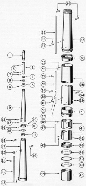
magnification. Figure 6-5 shows the upper telescope system assembly Part I. All bubble
numbers in Section 6F1 refer to Figure 6-5
unless otherwise specified.
Ill. No.
Drawing Number
Num- ber Re- quired
Nomenclature
1
P-1257-7
1
Fifth reduced tube section
2
P-1253-3
1
Fourth reduced tube section
3
P-1253-1
1
Upper eyepiece lens mount
4
P-1253-2
1
Upper eyepiece lens clamp ring
5
P-1260-18
4
Upper eyepiece lens mount and fifth and fourth reduced tube section lockscrews
6
P-1260-19
1
Upper, eyepiece lens clamp ring lockscrew
7
P-1260-23
2
Fourth and third reduced tube section lockscrews
8
P-1396-5
1
Upper eyepiece lens
9
P-1254-4
1
Third reduced tube section
10
P-1253-5
1
Telemeter lens mount
11
P-1253-5A
1
Telemeter lens clamp ring
12
P-1260-20
1
Telemeter lens mount angular alignment lockscrew
13
P-1260-21
2
Third and second reduced tube section lockscrews
14
P-4260-24
2
Telemeter lens clamp ring lockscrews
15
P-1396-6
1
Telemeter lens
16
P-1396-6A
1
Telemeter lens lockscrew
17
P-1253-6
1
Second reduced tube section
18
P-1260-22
4
Second and first reduced tube section lockscrews
19
P-1361-5
2
Tape straps
20
P-1361-7
1
Air line adapter (soldered)
21
P-1362-14
1
Air line strap (soldered)
22
P-1361-6
1
Air line section
23
P-1204-1
1
First reduced tube section
24
P-1361-4
2
Tape straps
25
P-1361-6
1
Air line section continuation
Ill. No.
Drawing Number
Num- ber Re- quired
Nomenclature
26
P-1362-13
1
Air line strap
27
P-1422-1
2
Air line strap lockscrews
28
P-1204-3
1
Sixth inner tube section
29
P-1179-24
8
Sixth inner tube section lower end coupling lockscrews
30
P-1204-2
1
Sixth inner tube section upper end coupling
31
P-1204-4
1
Sixth inner tube section lower end coupling
32
P-1260-11
4
Sixth inner tube section and upper end coupling lockscrews
33
P-1310-34
4
First reduced tube section and sixth inner tube section upper end lockscrews
34
P-1361-3
2
Tape straps
35
P-1361-6
1
Air line section continuation
36
P-1362-6
1
Air line coupling
37
P-1362-7
1
Air line section
38
P-1362-13
1
Air line strap
39
P-1362-14
2
Air line straps (soldered)
40
P-1422-1
2
Air line strap lockscrews
41
P-1204-5
1
Fifth inner tube section
42
P-1179-23
8
Fifth inner tube section upper and lower end lockscrews
43
P-1179-23
4
Upper objective lens mount lockscrews
44
P-1179-35
1
Upper objective lens clamp ring lockscrew
45
P-1204-6
1
Upper objective lens mount
46
P-1204-7
1
Upper objective lens clamp ring
47
P-1362-7
1
Air line section continuation
48
P-1396-7A
1
Upper objective lens flint element
49
P-1396-7B
1
Upper objective lens crown element
50
P-1417-5
1
Upper objective lens spacer ring
a. Fifth reduced tube section. The fifth
reduced tube section (1) is made of brass rod,
and is 5 1/4 niches in length. It serves to provide
the necessary distance between the skeleton
head assembly and the fourth reduced tube
section (2).
The upper part is smooth turned, to serve as
an alignment support section, and has a threaded
periphery section. The alignment support and
threaded periphery sections receive the internal
threaded and counterbored alignment support
sections in the lower part of the skeleton head
306
Figure 6-5. Upper telescope system assembly, Part I.
307
(1, Figure 6-4) and are secured together with
two opposite lockscrews (55) of the skeleton
head assembly.
A bearing flange of nominal width immediately
follows the threaded periphery section, and has
a diameter coinciding with the skeleton head
periphery, a sliding fit in the straight bored
1.99 external section of the outer taper section
(1, Figure 6-2). The bearing flange in the lower
part is the same thickness and diameter and is
also a sliding fit in the straight bored 1.99 external section of the outer taper section. It
coincides with the periphery wall of the fourth
reduced tube section (2).
The external body of this section between both
bearing flanges is tapered outward from the
upper bearing flange down to the lower bearing
flange. The inner circumference of the tapered
section is counterbored with a uniform tapered
wall thickness of 3/32 inch, commencing from
the lower counterbored section and ending
at the upper bored section for light transmission, and is threaded for antireflection.
The upper part is bored straight a distance of
1 inch, with a straight counterbored section of
1.110 inch in length in the lower part.
The lower part is smooth turned, serves as an
alignment support section, and has a threaded
periphery section preceding it. The alignment
support and threaded periphery sections receive
the internal threaded and alignment support
sections in the upper part of the fourth reduced
tube section, and are secured together with two
opposite lockscrews (5). These lockscrews are
inserted in countersunk clearance holes in the fourth reduced tube section (2 and screwed into
tapped holes in the fifth reduced tube section
lower alignment support section.
At assembly, four shallow vertical slots are
provided in both bearing flanges, two opposite
the others to provide clearance for the prism
tilt and change of power shifting wire tapes
(38, Figure 4-28).
b. Fourth reduced tube section. The
fourth reduced tube section (2) is made of brass
tubing, and is 6.450 inches in length. The external diameter coincides with the bearing
flange diameter of the fifth reduced tube section
(1) and is a sliding fit in the straight bored
1.99 external section of the outer taper section.
It is bored for light transmission, leaving
a nominal wall thickness of 0.080 inch, and is
threaded for antireflection between the upper
and lower counterbored sections.
The upper part is counterbored a short
distance, serving as an alignment support
section with an additional counterbored threaded
section to receive the alignment support section
of a sliding fit and the threaded periphery
section of the fifth reduced tube section lower
part (1).
The lower part is provided with three counterbored sections. The small counterbored section
2 inches long carries the mounted upper eyepiece
lens (8) and its mount (3). Two opposite axial
slots of appropriate length are provided in the
wall near the lower part of this counterbored
section for the insertion of two opposite special
screws into tapped holes in the upper eyepiece
lens mount (3). These two special inserted screws
serve to carry the upper eyepiece lens (8) and
its mount (3) vertically during collimation of
the upper telescope system.
The medium diameter counterbored section
is threaded to engage on the upper threaded
periphery section of the third reduced tube
section (9), while the large counterbored section
serves as an alignment support of a sliding fit
over the upper alignment support section of the
third reduced tube section, and are secured
together with two lockscrews (7). These lockscrews are inserted in countersunk clearance
holes in the lower part of the fourth reduced
tube section and screwed into tapped holes in
the upper alignment support section of the third
reduced tube section (9).
At assembly, four vertical shallow slots are
provided in this reduced tube section, two
opposite the others, to provide clearance for
the prism tilt and change of power shifting
wire tapes (38, Figure 4-28).
c. Upper eyepiece lens, mount, and clamp
ring. 1. Upper eyepiece lens. The upper
eyepiece lens (8) is made of two optical elements. It consists of a piano concave flint element cemented to a double convex crown
element, forming a positive doublet. It is
mounted in the upper eyepiece lens mount (3)
with the crown element resting in the seat of
308
the mount, and is secured with an upper eyepiece
lens clamp ring (4) which is secured with its
lockscrew (6).
2. Upper eyepiece lens mount. The upper
eyepiece lens mount (3) is made of brass tubing,
and is 1 1/4 inch in length. It is bored for light
transmission and has two counterbored sections.
The small counterbored section carries the
upper eyepiece lens doublet (8), while the large
counterbored section is threaded to carry the
threaded periphery of the upper eyepiece lens
clamp ring (4). The lower face is chamfered
from the bore at an angle of 15 degrees outward. Two
opposite clearance holes are located in the wall
of this chamfered section for the insertion
of a special pair of calipers in order that, the
assembled mount can be carried out of the lower
part of the fourth reduced tube section (2).
The mount is an axial sliding fit in the small
counterbored section in the lower part of the
fourth reduced tube section.
The mount is moved axially during collimation by the two special screws inserted in the
opposite axial slots in the fourth reduced tube
section and screwed into opposite tapped holes
in the mount. This axial movement is necessary
to obtain correct adjustment for definition and
the elimination of parallax in the upper and lower
telescope systems during collimation. The mount
is secured in the fourth reduced tube section
(2) with two lockscrews (5) after, collimation.
These lockscrews are inserted in countersunk
clearance holes in the fourth T educed tube section
(2) and screwed into tapped holes in the mount.
Two opposite narrow air channel slots are
provided in the periphery of the mount to allow
sufficient clearance for the passage of nitrogen.
3. Upper eyepiece lens clamp ring. The
upper eyepiece lens clamp ring (4) is made of
brass tubing, and is of nominal thickness and
width. The periphery is threaded for engagement
in the counterbored threaded section in the upper
part of the eyepiece lens mount (3) to secure
the lens doublet. The clamp ring is bored for
light transmission, and is threaded for antireflection. Two opposite slots are provided in
the face of the clamp ring for the insertion of a
special wrench. The clamp ring is secured with a
lockscrew (6) which is inserted in a countersunk
clearance hole in the mount (3) and screwed into
the tapped hole in the clamp ring.
d. Third reduced tube section. The third
reduced tube section (9) is made of brass rod,
and is 17.634 inches in length. The upper part
is smooth turned a short distance and serves
as an alignment support section with a threaded
periphery section preceding it. The threaded
periphery and alignment support section receive
the counterbored alignment support section
and internal threaded section in the lower part
of the fourth reduced tube section (2), and are
secured together with two lockscrews (7).
The external diameter is turned straight 2
inches below the alignment support section.
From this point the wall is tapered outward
down to the 5/8-inch straight section.
The lower part is provided with two counterbored sections. The small counterbored section
carries the telemeter lens mount (10) of a sliding
fit, and is provided with two opposite vertical
air channel slots for the passage of nitrogen.
These two channel slots extend vertically
inch above the small counterbored shoulder.
A circumferential slot of appropriate length
with an additional similar recess is provided in
the wall and located in the center of this small
counterbored section, to accommodate an angular alignment lockscrew (12). It is used to
permit angular adjustment of the telemeter
lens mount (10) during collimation, so that
the telemeter lens line will lie in a true vertical
plane. The angular alignment lockscrew is
inserted in the circumferential slot and screwed
in a tapped hole in the telemeter lens mount (10),
while the head of the lockscrew rests on the
circumferential recess face.
The large counterbored section is threaded
and serves as an alignment support section to
receive the upper threaded periphery alignment
support section of the second reduced tube
section (17) to which it is secured with two
opposite lockscrews (13).
The inner surface of this reduced tube section
is bored tapered, commencing from a diameter of
1.420 inch in the upper part to a diameter of
1.590 inch, in a length of 3 21/32 inches, and is
threaded for antireflection starting from the
upper end for a distance of 3.152 inches. The
remainder of the inner surface is counterbored
tapered from the small straight counterbored
309
section in the lower part to the diameter of
1.590 inch, and threaded for antireflection.
At assembly, four vertical shallow slots are
provided in both shoulder flanges, to provide
clearance for the prism tilt and change of
power shifting wire tapes (38, Figure 4-28).
e. Telemeter lens, mount, and clamp
ring. 1. Telemeter lens. The telemeter lens
(15) is made of one ordinary crown piano convex
element. The piano surface is etched with
vertical and horizontal calibrations in degrees
of true field, and provides a means of measuring
the angular size of a target. Refer to Section
4U7, Paragraph a, for further detail.
The telemeter lens is placed in the image
plane of the upper telescope and first real
image plane of the periscope, so that the graduations appear to vibrate in unison with the image,
and observation is easier.
The telemeter lens periphery is provided with
a vertically stoned groove. A lockscrew (16)
in the telemeter lens mount (10) fits in this
groove, thus permitting the lens to be reassembled in its original position, and preventing
any angular shift of the telemeter lens in the
mount. The piano surface of the lens is placed
toward the seat of the mount, and is secured
with a clamp ring (11) and lockscrew (14).
2. Telemeter lens mount. The telemeter
lens mount (10) is made of brass tubing and is
1/2 inch in width. Its inside diameter is bored
for light transmission. The mount is a sliding
fit into the counterbored section in the lower
part of the third reduced tube section (9),
and is secured after collimation with an angular
alignment lockscrew (12). The mount is counterbored to carry the telemeter lens (15) and
telemeter lens clamp ring (11). The mount is
provided with a small lockscrew (16) located
as a permanent fitting and filed off so that the
protruding section of the lockscrew will allow
the free disassembly and reassembly of the
telemeter lens in the mount. This protruding
section of the lockscrew when engaged in the
stoned vertical groove in the telemeter lens
periphery, prevents it from shifting angularly
in the mount and also provides the original
reassembly of the lens in the mount.
3. Telemeter lens clamp ring. The telemeter lens clamp ring (11) is made of brass
tubing, and is of nominal thickness and width.
It is a push fit in the counterbored section in the telemeter lens mount (10). This clamp ring
fits snugly against the convex surface of the
telemeter lens, and is secured with two opposite
lockscrews (14). These lockscrews are inserted
in countersunk clearance holes in the telemeter
lens mount (10) and screwed into tapped holes
in the clamp ring. The bore of the clamp ring
is threaded for antireflection. The clamp ring
is provided with opposite holes for the insertion
of a special pair of calipers for the removal
of the assembled telemeter lens mount (10).
f. Second reduced tube section. The
second reduced tube section (17) is made of
phosphor bronze and is 22 1/2 inches in length.
It serves to enclose the light rays to their
designed clear aperture area for its length and
provides a partial assembly of the upper telescope system.
The upper part has a threaded periphery
alignment support section to receive the internal
threaded section of the lower part of the third
reduced tube section (9) and is secured together
with two lockscrews (13). These lockscrews are
inserted in countersunk clearance holes in the
third reduced tube section (9) and screwed in
tapped holes in the upper threaded periphery
alignment support section of the second reduced
tube section.
The external circumference is tapered from
the upper alignment support section downward
to the straight turned shoulder section. The
inner surface is bored tapered for light transmission and threaded for antireflection, commencing from the small straight counterbored
section in the lower part.
The straight turned shoulder 1 1/4 inches long
in the lower part provides sufficient wall area
for the small counterbored and larger counterbored threaded sections. The small counterbored section serves as an alignment support
section, a sliding fit over the upper alignment
support section of the first reduced tube section
(23). The large counterbored threaded section
engages on the upper threaded periphery of the
first reduced tube section (23) and is secured to it with four lockscrews (18).
310
At assembly an air line adapter (20) is
soldered to the upper periphery wall of this
reduced tube section over a small clearance hole
for the introduction of nitrogen. An air line
strap (21) is soldered to the periphery wall of
this reduced tube section several inches below
the air line adapter (20) to retain the air line
section (22). This air line section is connected
in the opening of the air line adapter (20) and
extends downward over the lower joint of this
reduced tube section.
Two opposite tape straps (19) are soldered to
the upper periphery wall of this reduced tube
section, located 2 3/4 inches from the upper end,
and retain the prism tilt and change of power
shifting wire tapes (38, Figure 4-28) at their
required vertical centerline position.
g. Air line adapter. The air line adapter
(20) consists of a piece of flat brass air line
with the upper end closed, and is provided with a
1/8-inch diameter drilled hole located 7/64 inch
from the upper end. The adapter is soldered to
the periphery of the upper part of the second
reduced tube section (17) with both 1/8-inch
holes in coincidence. The lower opening of the
adapter receives the air line section (22).
h. First reduced tube section. The first
reduced tube section (23) is made of cast
phosphor bronze, and is 22.646 inches in length.
It serves to enclose the light rays to their
designed clear aperture area for this, length
and provides partial assembly of the upper
telescope system.
The upper part is smooth turned, to serve as
an alignment support section, and has threaded
periphery section. The alignment support and
threaded periphery sections receive the internal
threaded and counterbored alignment support
sections of the lower part of the second reduced
tube section (17) and are secured together with
four lockscrews (18). These lockscrews are
inserted in countersunk clearance holes in the
second reduced tube section (17) and screwed
into tapped holes in 4 the upper alignment support
section of the first reduced tube section.
A shoulder flange of nominal width immediately follows the threaded periphery section,
and has a diameter coinciding with the lower
part of the second reduced tube section (17).
The bearing flange in the lower part is the same
width as the upper shoulder flange, except that
its diameter is within a few thousandths-inch
smaller than the outer tube inner diameter
in order to provide a sliding fit.
The external body of this section between
the upper shoulder flange and lower bearing
flange is tapered outward and downward. The
inner circumference of this reduced tube
section is bored tapered its entire length with a
uniform wall thickness of 7/64 inch between
the flanges for light transmission. It is threaded
for antireflection.
The lower part is smooth turned and serves
as an alignment support section in the bored
diameter of the sixth inner tube section upper
end coupling (30). The threaded periphery
section preceding this alignment support section
engages in the internal threaded section in the
sixth inner tube section upper end coupling (30)
and is secured with four lockscrews (33). These
lockscrews are inserted in countersunk clearance
holes in the upper part of the sixth inner tube
section (28) with clearance holes in its upper end
coupling (30) and screwed in tapped holes in the
lower alignment support section of the first
reduced tube section (23).
The central part of this reduced tube section
is provided with a removable air line strap (26)
to retain the air line section continuation (25).
It is secured with two lockscrews (27) which are
inserted in clearance holes in the air line strap
and screwed into tapped holes in the periphery
wall of this reduced tube section. The air line
continuation (25) is the extension of the air
line section (22) of the second reduced tube
section (17), and extends the entire length of
this reduced tube section.
Four tape slots are provided in both flanges,
two opposite the others to provide free movement of the prism tilt and change of power
shifting wire tapes (38, Figure 4-28), Two tape
straps (24) are soldered to opposite sides on the
periphery, located 2 1/8 inches from the upper
shoulder flange to provide vertical guidance
to the shifting wire tapes.
One air port is provided in the lower part,
and is located 1 inch from the lower bearing
flange. A wire screen is placed in the countersunk
311
section of a clearance hole with a brass bushing
soldered in the countersunk section against the
wire screen. The bushing is filed down to conform to the contour of this reduced tube section
periphery.
i. Sixth inner tube section. The sixth inner
tube section (28) is made of brass tubing and is
31 1/4 inches in length. Its inner and outer
diameter are uniform the entire length.
The upper part is a push fit and is soldered
on the lower alignment support section of the
sixth inner tube section upper end coupling
(30) with four lockscrews (32). These lockscrews
are inserted in soldered countersunk clearance
holes in the upper part of the sixth inner tube
section and screwed into soldered tapped holes
in the lower alignment support section of the
sixth inner tube section upper coupling (30),
to form a permanent joint.
The lower part of this inner tube section is a
push fit and is soldered on the upper alignment
support section of the sixth inner tube section
lower end coupling (31) with eight lockscrews
(29). These lockscrews are inserted in soldered
countersunk clearance holes in the lower part
of the sixth inner tube section, and screwed
into soldered tapped holes in the upper alignment
support section of the sixth inner tube section
lower end coupling (31) to form a permanent
joint.
The aid line section, continuation (35) of this
inner tube section extending downward from
the airline section continuation (25) of the first
reduced tube section (23) and the air line
section (22) of the second reduced tube section
(17), ends in the lower part of this inner tube
section. An air line coupling (36) is soldered
in the lower end of the air line section continuation (35). The upper part of this continuation
(35) is retained by two soldered air line straps
(39) to the periphery wall of this inner tube
section.
The air line section (37) located in the lower
part of this inner tube section, connects to the
soldered air line coupling (36) and is retained
in place with a removable air line strap (38)
which is secured with two lockscrews (40).
These lockscrews are inserted in clearance
holes in the air line strap (38) and screwed into
tapped holes in the periphery wall of the lower
part of this inner tube section.
Two opposite tape straps (34) are soldered to
the lower part of this inner tube section periphery
wall, to provide vertical guidance to the prism
tilt and change of power shifting wire tapes
(38, Figure 4-28).
j. Sixth inner tube section upper and
lower end couplings. 1. Sixth inner tube
section upper end coupling. The sixth
inner tube section upper end coupling (30)
is identical to the sixth inner tube section upper
end coupling (26, Figure 4-20) Type II periscope.
Refer to Section 4I1.
At assembly it is provided with a vertical
air line slot to allow for clearance of the air
line section continuation (25) extending downward from the first reduced tube section (23).
There are no air ports in this coupling as there
are in the Type II periscope.
2. Sixth inner tube section lower end
coupling. The sixth inner tube section lower
end coupling (31) is identical to the sixth inner
tube section lower end coupling (27, Figure
4-20) of the Type II periscope. Refer to Section 4I1.
At assembly it is provided with a vertical
air line slot to provide clearance for the air
line section (37) extending downward from the
lower part of the sixth inner tube section (28).
k. Fifth inner tube section. The fifth
inner tube section (41) is identical to the fifth
inner tube section (34, Figure 4-20) of the Type
II periscope. Refer to Section 411.
At assembly it is provided with a vertical
air line slot to allow for clearance of the air
line section continuation (47) of this section
extending downward from the air line section
(37) of the sixth inner tube section (28).
l. Upper objective lens, mount, spacer
ring, and clamp ring. 1. Upper objective
lens. The upper objective lens is made of
two optical elements. It consists of a plano
concave flint element (48) separated from the
crown element with a spacer ring (50). The
second is a double convex crown element (49)
forming an air space doublet. The doublet is
312
mounted on the upper objective lens mount
(45) and is secured with a threaded clamp
ring (46) and its lockscrew (44).
2. Upper objective lens mount. The upper
objective lens mount (45) is identical to the
upper objective lens mount (38, Figure 4-20
of the Type II periscope. Refer to Section 4I1.
3. Upper objective lens spacer ring. The
upper objective lens spacer ring (50) is identical
to the upper objective lens spacer ring (40
Figure 4-20) of the Type II periscope. Refer to
Section 4I1.
4. Upper objective lens clamp ring. The
upper objective lens clamp ring (46) is identical
to the upper objective lens clamp ring (39
Figure 4-20) of the Type II periscope. Refer
to Section 4I1.
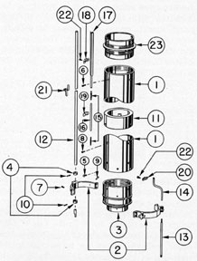
6F2. Description of the upper telescope system
assembly Part II: second, third, and fourth inner tube
sections. These three inner tube sections have new
lenses, but form the necessary inner tube bodies
to enclose the inter-objective parallel light ray
that are deflected downward to the magnifying
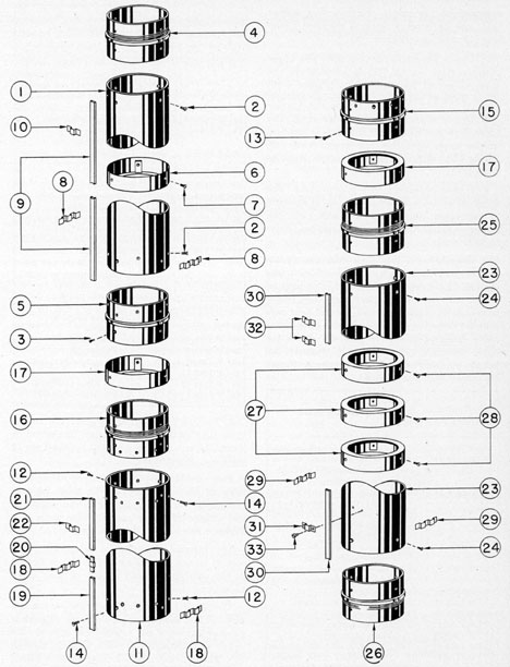
lower telescope system. Figure 6-6 shows the
upper telescope system assembly Part II. All
bubble numbers in Section 6F2 refer to Figure
6-6 unless otherwise specified.
Ill. No.
Drawing Number
Num- ber Re- quired
Nomenclature
1
P-1205-1
1
Fourth inner tube section
2
P-1179-24
1
Fourth inner tube section upper and lower end lockscrews (soldered)
3
P-1179-24
4
Fourth inner tube section lower end coupling lockscrews and third inner tube section upper end coupling lockscrews
4
P-1204-8
1
Fourth inner tube section upper end coupling
5
P-1205-2
1
Fourth inner tube section lower end coupling
6
P-1207-5
1
Diaphragm
7
P-1310-13
3
Diaphragm lockscrews
8
P-1361-3
2
Tape straps
9
P-1362-7
1
Air line section continuation
10
P-1362-14
7
Air line straps (soldered)
11
P-1205-1
1
Third inner tube section
12
P-1179-24
16
Third inner tube section upper and lower end coupling lockscrews (soldered)
Ill. No.
Drawing Number
Num- ber Re- quired
Nomenclature
13
P-1179-24
4
Third inner tube section lower end coupling and second inner tube section upper end coupling lockscrews
14
P-1179-53
6
Diaphragm lockscrews
15
P-1205-2
1
Third inner tube section lower end coupling
16
P-1205-3
1
Third inner tube section upper end coupling
17
P-1207-6
2
Diaphragms
18
P-1361-3
2
Tape straps
19
P-1362-5
1
Air line section
20
P-1362-6
1
Air line coupling
21
P-1362-7
1
Air line section continuation
22
P-1362-14
6
Air line straps (soldered)
23
P-1205-1
1
Second inner tube section
24
P-1179-24
8
Second inner tube section upper and lower end coupling lockscrews (soldered)
25
P-1205-3
1
Second inner tube section upper end coupling
26
P-1205-4
1
Second inner tube section lower end coupling
27
P-1207-5
3
Diaphragms
28
P-1310-13
9
Diaphragm lockscrews
29
P-1361-3
2
Tape straps
30
P-1362-5
1
Air line section continuation
31
P-1362-13
1
Air line strap
32
P-1362-14
6
Air line straps (soldered)
33
P-1422-1
2
Air line strap lockscrews
a. Fourth inner tube section. The fourth
inner tube section (1) is identical to the fourth
inner tube section (1, Figure 4-21) of the Type II
periscope. Refer to Section 4I2.
Two tape straps (8) are soldered to opposite
sides of the periphery in the lower part to
provide the vertical guidance to the prism tilt
and change of power shifting wire tapes (38,
Figure 4-28).
The internal diameter of this inner tube
section carries a diaphragm (6) which is located
in the central part and is secured with three
lockscrews (7).
The upper part of this inner tube section is a
push fit and is soldered on the lower alignment
support section of the fourth inner tube section
upper end coupling (4) with eight lockscrews
(2). These lockscrews are inserted in soldered
countersunk clearance holes in the upper part
of the fourth inner tube section and screwed into
313
Figure 6-6. Upper telescope system assembly, Part II.
314
soldered tapped holes in the lower alignment
support section of the fourth inner tube section
upper end coupling (4) to form a permanent
joint.
The lower part of this inner tube section is a
push fit and is soldered on the upper alignment
support section of the fourth inner tube section
lower end coupling (5) with eight lockscrews
(3). These lockscrews are inserted in soldered
countersunk clearance holes in the lower part
of the fourth inner tube section and screwed
into soldered tapped holes in the upper alignment support section of the fourth inner tube
section lower end coupling (5).
The air line section continuation (9) extends
the entire length of this inner tube section, and
is part of the air line section continuation (47,
Figure 6-5) of the fifth inner tube section (41)
and the air line section (37) of the sixth inner
tube section (28). It is retained to this inner
tube section with seven air line straps (10),
which are soldered to the periphery wall.
b. Fourth inner tube section upper end
coupling, diaphragm, and lower end coupling. 1. Fourth inner tube section upper
end coupling. The fourth inner tube section
upper end coupling (4) is identical to the fourth
inner tube section upper end coupling (5, Figure
4-21) of the Type II periscope. Refer to Section 4I2.
At assembly it is provided with a vertical
air line slot to allow for clearance of the air
line section continuation (47, Figure. 6-5) extending downward from the fifth inner tube
section (41).
2. Diaphragm. The diaphragm (6) is identical to the diaphragm (7, Figure 4-21) of the
Type II periscope. Refer to Section 4I2.
3. Fourth inner tube section lower end
coupling. The fourth inner tube section
lower end coupling (5) is identical to the fourth
inner tube section lower end coupling (6,
Figure 4-21) of the Type II periscope. Refer
to Section 4I2.
At assembly it is provided with a vertical
air line slot to allow for clearance of the air
line section continuation (9) extending downward
from the fourth inner tube section (1).
c. Third inner tube section. The third
inner tube section (11) is identical to the third
inner tube section (11, Figure 4-21) of the
Type II periscope. Refer to Section 4I2.
Two tape straps (18) are soldered to opposite
sides on the periphery wall in the lower part
to provide vertical guidance to the prism tilt
and change of power shifting wire tapes (38,
Figure 4-28).
The upper part of the third inner tube
section (11) is a push fit and is soldered on the
lower alignment support section of the third
inner tube section upper end coupling (16) with
eight lockscrews (12). These lockscrews are
inserted in soldered countersunk clearance holes
in the upper part of the third inner tube section
and screwed into soldered tapped holes in the
lower alignment support section of the third
inner tube section upper end coupling (16) to
form a permanent joint.
The lower part of this inner tube section is a
push fit and is soldered on the upper alignment
support section of the third inner tube section
lower end coupling (15) with eight lockscrews
(12). These lockscrews are inserted in soldered
countersunk clearance holes in the lower part
of the third inner tube section and screwed
into soldered tapped holes in the upper alignment
support section of the third inner tube section
lower end coupling (15).
The air line section continuation (21) extending downward on this inner tube section, ends
in its upper part and is retained to the periphery
wall of the third inner tube section with two
soldered air line straps (22). An air line coupling
(20) is soldered in the lower end of the air line
section continuation (21).
The air line section (19) located in the upper
part of this inner tube section, connects to the
soldered air line coupling (20) and is retained
in place with four air line straps (22) soldered
on the periphery wall of this inner tube section.
d. Third inner tube section upper end
coupling, diaphragms, and lower end coupling. 1. Third inner tube section upper end
coupling. The third inner tube section upper
end coupling (16) is identical to the third inner
tube section upper end coupling (17, Figure
315
4-21) of the Type II periscope. Refer to Section 4I2.
At assembly it is provided with a vertical air
line slot to allow for clearance of the air line
section continuation (9) extending downward
from the fourth inner tube section (1).
2. Diaphragms. The two diaphragms (17)
are identical to the two diaphragms (18, Figure
4-21) of the Type II periscope. Refer to Section 4I2.
One is secured in the bore in the lower part
of the third inner tube section upper end coupling (16) with its side wall facing downward.
It is secured with three lockscrews (14), which
are inserted in countersunk clearance holes
in the upper part of the third inner tube section
(11) in clearance holes in its upper end coupling
(16) and screwed into tapped holes in the
diaphragm (17).
The second diaphragm (17) is secured with
three lockscrews (14) which are inserted in
countersunk clearance holes in the lower part
of the third inner tube section (11) in clearance
holes in its lower end coupling (15) and screwed
into tapped holes in the diaphragm (17).
3. Third inner tube section lower end
coupling. The third inner tube section lower
end coupling (15) is identical to the third inner
tube section lower end coupling (16, Figure
4-21) of the Type II periscope. Refer to Section 4I2.
At assembly it is provided with a vertical
air line slot to allow for clearance of the air
line section (19) of the third inner tube section
(11).
e. Second inner tube section. The second
inner tube section (23) is made of brass tubing
and is 96.400 inches in length. The inner and
outer diameters are uniform throughout the
entire length.
The upper part of this inner tube section is a
push fit and is soldered on the lower alignment
support section of the second inner tube section
upper end coupling (25) with four lockscrews
(24). These lockscrews are inserted in soldered
countersunk clearance holes in the upper part
of the second inner tube section and screwed into
soldered tapped holes in the lower alignment
support section of the second inner tube section
upper end coupling (25) to form a permanent
joint.
The lower part of this inner tube section is a
push fit and is soldered on the upper alignment
support section of the second inner tube section
lower end coupling (26) with four lockscrews
(24). These lockscrews are inserted in soldered
countersunk clearance holes in the lower part
of the second inner tube section (23) and screwed
into soldered tapped holes in the upper Alignment support section of the second inner tube
section lower end coupling (26) to form a
permanent joint.
Two tape straps (29) are soldered on opposite
sides of the periphery in the lower part to
provide vertical guidance for the prism tilt
and change of power shifting wire tapes (38,
Figure 4-28).
The air line section continuation (30) extends
the entire length of this inner tube section from
the air line section (19) of the third inner tube
section (11). This air line section continuation
(30) is retained to the periphery wall of this
inner tube section with six soldered air line
straps (32) and a removable air line strap (31)
secured with two lockscrews (33). These lockscrews are inserted in clearance holes in the air
line strap (31) and screwed into tapped holes
in the periphery wall of this inner tube section.
The internal diameter of this inner tube section
carries three diaphragms (27). The upper
diaphragm is located 42 13/16 inches from its
upper end. The second diaphragm is located
18 inches from the upper diaphragm, while
the lower diaphragm is located 9 1/2 inches from
the center diaphragm. Each diaphragm is
located with its side wall facing upward and is
secured with three lockscrews (28), which are
inserted in countersunk clearance holes in this
inner tube section and screwed into tapped holes
in each diaphragm.
f. Second inner tube section, upper end
coupling, diaphragms, and lower end coupling. 1. Second inner tube section upper
end coupling. The second inner tube section
upper end coupling (25) is identical to the
second inner tube section upper end coupling
(25, Figure 4-21) of the Type II periscope.
Refer to Section 4I2.
316
At assembly it is provided with a vertical
air line slot to allow for clearance of the air
line section (19) extending downward from the
third inner tube section (11).
2. Diaphragms. The three diaphragms (27)
are identical to the diaphragm (7, Figure 4-21)
of the Type II periscope. Refer to Section 4I2.
3. Second inner tube section lower end
coupling. The second inner tube section lower
end coupling (26) is identical to the second
inner tube section lower end coupling (26, Figure
4-21) of the Type II periscope. Refer to Section 4I2.
6F3. Disassembly of Part I. The first, second, third,
fourth, and fifth reduced tube sections and the
fifth and sixth inner tube sections are disassembled in the following manner. (All bubble
numbers in Sections 6F3 and 4 refer to Figure
6-5 unless otherwise specified.)
1. Separation of the lower part of the fifth
reduced tube section (1) from the upper part
of the fourth reduced tube section (2) proceeds
as follows:
2. Remove the two lockscrews (5) from the
upper part of the fourth reduced tube section
(2). These lockscrews are unscrewed from tapped
holes in the fifth reduced tube section (1).
3. Unscrew the fifth reduced tube section (1)
from the upper part of the fourth reduced tube
section (2).
4. Separation of the lower part of the fourth
reduced tube section (2) from the upper part
of the third reduced tube section }(9 degrees) proceeds
as follows:
5. Remove the two lockscrews (7) from the
lower part of the fourth reduced tube section
(2). These lockscrews are unscrewed from
tapped holes in the third reduced tube section
6. Unscrew the fourth reduced tube section
(2) from the upper part of the third reduced
tube section (9).
7. Remove the two lockscrews (5) from the
upper eyepiece lens mount (3). These lockscrews are unscrewed from the tapped holes
in the mount, and are carried out of countersunk clearance holes in the lower part of the
fourth reduced tube section (2).
8. Using a special pair of calipers inserted
in opposite holes in the lower part of the upper
eyepiece lens mount (3), slide the upper eye
piece lens mount out from the lower part of the
fourth reduced tube section (2), removing the
assembled mount with the upper eyepiece
lens (8) its clamp ring (4) and its lockscrew (6).
9. Remove the lockscrew (6) from the upper
eyepiece lens mount (3) and its clamp ring (4).
This lockscrew is unscrewed from the tapped hole
in the clamp ring (4).
10. Using a special wrench, unscrew the
upper eyepiece lens clamp ring (4) and remove
it from the upper eyepiece lens mount (3).
11. Place the upper eyepiece lens mount (3)
on a piece of lens tissue, resting it on its upper
face. Using a piece of lens tissue on the lower
face, press downward on the lens tissue and the
upper eyepiece lens (8) for its removal. Wrap
the lens doublet in clean lens tissue and store
it in a box to prevent scratches and breakage.
12. Separation of the third reduced tube section (9) from the upper part of the second
reduced tube section (17) proceeds as follows:
13. Remove the two lockscrews (13) from the
lower part of the third reduced tube section
(9). These lockscrews are unscrewed from
tapped holes in the second reduced tube section (17).
14. Unscrew the third reduced tube section (9)
from the upper part of the second reduced tube
section (17).
15. Remove the angular alignment lockscrew
(12) from the circumferential slot in the lower
part of the third reduced tube section. This
lockscrew is unscrewed from the tapped hole
in the telemeter lens mount (10) and is carried
out of the circumferential slot.
16. Remove the assembled telemeter lens
mount (10) from the lower part of the third
reduced tube section. This is done by means of
a special pair of calipers inserted in opposite
holes in the telemeter lens clamp ring (11). Slide
the telemeter lens mount out of the lower part
of the third reduced tube section, removing
the mount, telemeter lens (15), its clamp ring
(11), and its lockscrews (14).
317
17. Remove the two lockscrews (14) from
opposite sides of the telemeter lens mount
(10). These lockscrews are unscrewed from
tapped holes in the telemeter lens clamp ring
(11).
18. Turn the telemeter lens mount (10),
resting it on its lower face on a piece of lens
tissue. If necessary, using a piece of lens tissue,
press downward on the plano surface of the
telemeter lens (15), removing the lens and the
clamp ring (11). Wrap the lens in clean lens
tissue and store it in a box to prevent scratches
and breakage.
19. Separation of the second reduced tube
section (17) from the upper part of the first
reduced tube section (23) proceeds as follows:
20. Remove the four lockscrews (18) from the
lower part of the second reduced tube section
(17). These lockscrews are unscrewed from
tapped holes in the first reduced tube section
(23).
21. Unscrew the second reduced tube section
(17) from the upper part of the first reduced
tube section (23).
22. Separation of the first reduced tube
section (23) from the sixth inner tube section
upper end coupling (30) proceeds as fellows:
23. Remove the four lockscrews (33) from the
upper part of the sixth inner tube section (28).
These lockscrews are unscrewed from tapped
holes in the first reduced tube section (23).
24. Unscrew the first reduced tube section
(23) from the 6th inner tube section upper
end coupling (30).
25. Separation of the fifth inner tube section
(41) from the sixth inner tube section lower
end coupling (31) proceeds as follows:
26. Remove the four lockscrews (42) from
the fifth inner tube section (41). These lockscrews
are unscrewed from tapped holes in the lower
alignment support section of the sixth inner
tube section lower end coupling (31).
27. Unscrew the fifth inner tube section (41)
from the sixth inner tube section lower end
coupling (31). Carry the mounted upper objective lens (48 and 49), its mount (45), spacer
ring (50), clamp ring (46) and lockscrew (44)
With the fifth inner tube section (41).
28. Remove the four lockscrews (43), unscrewing them from tapped holes in the upper
objective lens mount (45), and carrying their
out of countersunk clearance holes in the fifth
inner tube section (41).
29. Remove the assembled upper objective
lens mount (45) from the fifth inner tube
section (41). The mount can be slid out from
either end. Remove the assembled mount (45)
with the upper objective lens (48 and 49),
upper objective lens spacer ring (50), upper
objective lens clamp ring (46), and its lockscrew (44).
30. Remove the lockscrew (44) from the
upper objective lens mount (45). This lockscrew
is unscrewed from the tapped hole in the upper
objective lens clamp ring (46).
31. Using a special wrench, unscrew the
upper objective lens clamp ring (46) from the
upper part of the upper objective lens mount
(45).
32. Place the lower part of the upper objective
lens mount (45) over a special padded wooden
block. The mount will slide down over the block,
with the upper objective lens elements (48
and 49) and the upper objective lens spacer
ring (50) remaining on the padded part of the
wooden block.
33. Wrap the flint and crown elements of the
upper objective lens air-space doublet (48 and
49) with lens tissue and store them in a box or
place them to one side to prevent scratches and
breakage.
6F4. Reassembly of Part I. The first, second, third,
fourth, and fifth reduced tube sections and the
fifth and sixth inner tube sections are reassembled in the following manner:
1. Using an air hose, blow out the internal
surfaces of the reduced and inner tube sections.
If various sized circular brushes are available,
they should be used first. This procedure should
be carried out with the clamp rings and lens
mounts.
2. Clean the upper eyepiece lens (8) with
clean lens tissue. Surface dust can be removed
318
with a rubber air bulb and a clean camel's
hair brush or a vacuum brush used with ether.
3. Place the upper eyepiece lens (8) in the
upper eyepiece lens mount (3). The crown
element of this doublet is placed toward the seat
of the mount.
4. Place the upper eyepiece lens clamp ring
(4) in the internal threaded section in the
upper part of the upper eyepiece lens mount
(3). Screw this clamp ring tight against the
plano face of the upper eyepiece lens doublet.
The lockscrew holes should coincide when the
lens doublet is tightened sufficiently.
5. Insert and secure the lockscrew (6),
inserting it in the countersunk clearance hole
in the mount (3) and screwing it into the tapped
hole in the upper eyepiece lens clamp ring (4).
6. Reassemble the assembled upper eyepiece lens mount (3) sliding it in the lower part
of the fourth reduced tube section (2). The clamp
ring side of the assembled mount should be
located upward.
7. Secure the upper eyepiece lens mount
(3) temporarily with two lockscrews (5). These
lockscrews are inserted into countersunk clearance holes in the fourth reduced tube section
(2) and screwed into tapped holes in the mount.
8. The connection of the lower part of the
fifth reduced tube section (1) in the upper
part of the fourth reduced tube section proceeds
as follows: Screw the lower part of the fifth
reduced tube section (1) into the upper part
of the fourth reduced tube section (2) until
the lockscrew holes coincide.
9. Insert and secure the two opposite lockscrews (5), inserting them in countersunk
clearance holes in the fourth reduced tube
section (2), screwing them into tapped holes
in the fifth reduced tube section (1), thus
securing the fourth and fifth reduced tube sections together.
10. The connection of the lower pat of the
fourth reduced tube section (2) on the upper
part of the third reduced tube section (9)
proceeds as follows: Screw the lower part of
the fourth reduced tube section (2) on the upper
part of the third reduced tube section (9) until
the lockscrew holes coincide.
11. Insert and secure the two opposite lockscrews (7), screwing them into countersunk
clearance holes in the fourth reduced tube section (2) and tapped holes in the third reduced
tube section (9). This secures the third and
fourth reduced tube sections together.
12. Clean the telemeter lens (15), in similar
manner to that outlined in Step 2 of this section
for the upper eyepiece lens (8).
13. Place the telemeter lens in the telemeter
lens mount (10). The etched graduations on the
piano side of the lens are placed toward the
seat in the mount, with the stoned vertical
slot meshing with the inward projecting lockscrew (16) in the mount.
14. Slide the telemeter lens clamp ring (11)
in the telemeter lens mount (10) to the convex
face of the telemeter lens (15) so that opposite
lockscrew holes of the mount and clamp ring
coincide.
15. Insert and secure the two lockscrews (14).
These lockscrews are inserted in countersunk
clearance holes in the telemeter lens mount
(10) and screwed into tapped holes in the
telemeter lens clamp ring (11).
16. Slide the telemeter lens (15) with its
mount (10) into the lower part of the third
reduced tube section (9), with the clamp ring
side of the assembled mount facing downward.
17. Insert and secure the angular alignment
lockscrew (12) in the circumferential slot in the
lower part of the third reduced tube section (9).
This lockscrew is screwed into the tapped hole
in the telemeter lens mount (10).
18. The connection of the lower part of the
third reduced tube section (9) on the upper part
of the second reduced tube section (17) proceeds
as follows: Screw the lower part of the third
reduced tube section (9) on the upper part
of the second reduced tube section (17), until
the lockscrew holes coincide.
19. Insert and secure the two lockscrews (13).
These lockscrews are inserted in countersunk
clearance holes in the third reduced tube section
(9) and screwed into tapped holes in the second
reduced tube section (17). This secures the
second and third reduced tube sections together.
319
20. The connection of the upper part of the
first reduced tube section (23) in the lower part
of the second reduced tube section (17) proceeds
as follows: Screw the upper part of the first
reduced tube section (23) into the lower part
of the second reduced tube section (17) until
the lockscrew holes coincide.
21. Insert and secure the four lockscrews
(18). These lockscrews are inserted in countersunk clearance holes in the second reduced
tube section (17) and screwed into tapped holes
in the first reduced tube section (23). This secures
the first and second reduced tube sections
together.
22. The connection of the lower part of the
first reduced tube section (23) in the sixth inner
tube section upper end coupling (30) proceeds
as follows: Screw the lower part of the first
reduced tube section (23) in the sixth inner tube
section upper end coupling (30), supporting
the assembled reduced tube sections during
this connection procedure, until the lockscrew
holes coincide.
23. Insert and secure the four lockscrews
(33). These lockscrews are inserted in countersunk clearance holes in the sixth inner tube
section (28) into clearance: holes in the sixth
inner tube section upper end coupling (30) and
screwed in tapped holes in the first reduced
tube section (23). This secures the first reduced
tube section and sixth inner tube section upper
end coupling together.
24. Clean the upper objective lens flint element (48) and the crown element (49) in similar
manner to the procedure described in Step 2,
of this section for the upper eyepiece lens (8).
25. Place the plano side of the flint element
(48) on the padded part of a special wooden
block. Place the upper objective lens spacer
ring (50) on the concave surface of the flint
element (48). Place the longest radius of the
double convex crown element (49) on the spacer
ring. Line up the periphery of both, elements and
the spacer ring.
26. Place the upper objective lens mount (45)
with the clamp ring side facing downward,
over the assembled upper objective lens doublet
and the padded wooden block. Turn the complete assembly with the padded block over, so
that the crown element (49) with the shortest
radius is resting in the seat of the mount.
27. Place the upper objective lens clamp
ring (46) in the threaded section in the upper
part of the upper objective lens mount (45).
Using a special wrench, screw this clamp ring
tightly against the plano side of the flint element
(48) until the lockscrew holes coincide.
28. Insert and secure the lockscrew (44).
This lockscrew is inserted in a countersunk
clearance hole in the upper objective lens mount
(45) and screwed into the tapped hole in the
upper objective lens clamp ring (46).
29. Slide the assembled upper objective lens
mount (45) into the fifth inner tube section (41).
The clamp ring side of the assembled mount
should face upward.
30. Secure the upper objective lens mount
(45) temporarily with four lockscrews (43).
These lockscrews are inserted in countersunk
clearance holes in the fifth inner tube section
(41) and screwed into tapped holes in the upper
objective lens mount (45).
31. The connection of the upper part of the
fifth inner tube section (41) on the sixth inner
tube section lower end coupling (31) proceeds
as follows: Screw the upper part of the fifth
inner tube section (41) on the lower alignment
support section of the sixth inner tube section
lower end coupling (31) until the lockscrew
holes coincide.
32. Insert and secure the four lockscrews (42). These lockscrews are inserted in countersunk clearance holes in the fifth inner tube
section (41), and screwed into tapped holes in
the sixth inner tube section lower end coupling
(31), securing the fifth inner tube section and
the sixth inner tube section lower end coupling
together.
33. Place a canvas boot over the upper end
of the fifth reduced tube section (1) and the
lower end of the fifth inner tube section (41)
to prevent foreign matter entering and adhering
to the cleaned lenses.
6F5. Disassembly of Part II. The second, third,
and fourth inner tube sections are disassembled
in the following manner (all bubble numbers in
Sections 6F5 and 6 refer to Figure 6-6 unless
otherwise specified):
320
1. Separation of the fourth inner tube section
lower end coupling (5) from the third inner tube
section upper end coupling (16) proceeds as
follows:
2. Remove the four lockscrews (3) from the
fourth inner tube section lower end coupling (5).
These lockscrews are unscrewed from tapped
holes in the upper alignment support section of
the third inner tube section upper end coupling
(16).
3. Unscrew the fourth inner tube section
lower end coupling (5) from the third inner
tube section upper end coupling (16). This
removes the fourth inner tube section (1) and
its lower end coupling (5) from its connection
with the third inner tube section (11) and its
upper end coupling (16). The diaphragm (6)
should of be removed from the central part
of the fourth inner tube section (1) unless the
periscope is known to be flooded with sea water.
To remove it would require the removal of either
the upper or lower end couplings which are
soldered to form a permanent joint.
4. Separation of the third inner tube section
lower end coupling (15) from the second inner
tube section upper end coupling (25) proceeds
as follows:
5. Remove the four lockscrews (13) from the
third inner tube section lower end coupling
(15). These lockscrews are unscrewed from the
tapped holes in the upper alignment support
section of the second inner tube section upper
end coupling (25).
6. Unscrew the third inner tube section lower
end coupling (15) from the second inner tube
section upper end coupling (25). This removes
the third inner tube section (11) and its lower
end coupling (15) from its connection with the
second inner tube section (23) and its upper
end coupling (25).
7. If it is necessary to remove the two diaphragms (17) from the third inner tube section
upper and lower end couplings (16 and 15),
remove the three lockscrews (14) each from the
upper} and lower parts of the third inner tube
section (11). These lockscrews are unscrewed
from tapped holes in each diaphragm (17). The
diaphragms can be pulled out easily, as they
are a push fit into these two couplings.
8. The three diaphragms (27) should not be
removed from the second inner tube section (23)
unless the periscope is known to be flooded
with sea water. To remove them would require
the removal of either the upper or lower end
couplings which are soldered to form a permanent joint.
6F6. Reassembly of Part (I. The second, third,
and fourth inner tube sections are reassembled
in the following manner:
1. Using an air hose, blow out the internal
surfaces of the second inner tube section.
If a circular brush is available, it should be used
first. This procedure is also carried out with each
succeeding inner tube section and couplings.
2. Place the two diaphragms (17) in the third
inner tube section upper and lower end couplings
(16 and 15). The side wall of each diaphragm
should face inward toward the inner part
of this inner tube section.
3. Insert and secure the three lockscrews
each (14) into each diaphragm (17). These
lockscrews are inserted into countersunk clearance holes in the upper and lower part of the
third inner tube section (11), further into
clearance holes in their respective couplings,
and screwed into tapped holes in the diaphragms.
4. The connection of the third inner tube
section lower end coupling (15) on the second
inner tube section upper end coupling (25)
proceeds as follows: Screw the third inner
tube section lower end coupling (15) on the
second inner tube section upper end coupling
(25).
5. Insert and secure the four lockscrews (13).
These lockscrews are inserted in countersunk
clearance holes in the third inner tube section
lower end coupling (15) and screwed in tapped
holes in the upper alignment support section
of the second inner tube section upper end
coupling (25). This secures the third inner
tube section lower end coupling and second
inner tube section upper end coupling together.
6. The connection of the fourth inner tube
section lower end coupling (5) on the third
inner tube section upper end coupling (16)
proceeds as follows: Screw the fourth inner
tube section lower end coupling (5) on the third
inner tube section upper end coupling (16).
321
7. Insert and secure the four lockscrews,(3).
These lockscrews are inserted in countersunk
clearance holes in the fourth inner tube section
lower end coupling (5) and screwed into tapped
holes in the upper alignment support section,
of the third inner tube section upper end coupling
(16). This secures the fourth inner tube section
lower end coupling and the third inner tube
section upper end coupling together.
8. Place a canvas boot over each end of this
assembly to prevent dust and foreign matter
from entering the cleaned inner tube sections.
G. RANGE FINDER
6G1. Description of the lower (split) objective lens
and mount assembly. The lower (split) objective
lens and mount assembly is identical to the
lower (split) objective lens and mount assembly
used in the Type II periscope. Refer to Section
4J2. The lower (split) objective lens halve,
crown (8A) and flint (8B, Figure 6-13) are
the only detail numbers which change, all other
parts are identical to those shown in Figure
4-22. This assembly serves the same purpose
and functions as the assembly used in the Type
II periscope.
6G2. Description of the objective operating mechanism assembly. This mechanism consists of the
necessary parts which transmit the displacement
of the lower (split) objective lens and mount
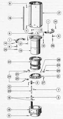
assembly, and is described as follows. Figure
6-7 shows this assembly. All bubble numbers
in Sections 6G2, 3, and 4 refer to Figure 6-7
unless otherwise specified.
Ill. No.
Drawing Number
Num- ber Re- quired
Nomenclature
1
P-1158-3
2
Mounting plates
2
P-1159-1
1
Operating gear pinion
3
P-1159-3
1
Stadimeter transmission coupling shaft coupling
4
P-1159-4
2
Mounting plate guide key a and integral shafts
5
P-1159-6
2
Mounting plate guide keys
6
P-1159-10
2
Mounting plate guides
7
P-1172-15
1
Operating gear pinion key
8
P-1179-23
4
Coupling sleeve lockscrews (upper end)
9
P-1179-23
4
Track sleeve and first inner tube section upper end coupling lockscrews
10
P-1179-27
2
Operating gear pinion lockscrews
11
P-1179-30
15
Coupling sleeve lockscrews(lower end)
12
P-1179-32
2
Mounting plate guide key lockscrews
Ill. No.
Drawing Number
Num- ber Re- quired
Nomenclature
13
P-1179-33
6
Mounting plate guide lockscrews
14
P-1179-177
2
Mounting plate guide key and shaft taper pins
15
P-1179-179
2
Stadimeter transmission shaft coupling taper pins
16
P-1362-5
1
Air line section continuation
17
P-1441-1
1
Coupling sleeve
18
P-1442-1
1
Track sleeve
19
P-1442-2
1
Sliding track
20
P-1442-3
1
Operating gear pinion shaft
21
P-1443-1
1
Operating gear retaining ring
22
P-1443-3
1
Operating gear
23
P-1449-1
1
Operating gear stop
24
P-1449-2
1
Observation position stop
25
P-1449-2
1
Maximum displacement stop
26
P-1449-3
2
Cam shoes
27
P-1453-1
6
Operating gear retaining ring lockscrews
28
P-1453-2
6
Operating gear retaining ring and track sleeve lockscrews
29
P-1453-3
8
Maximum displacement stop, observation position stop, and operating gear stop lockscrews
a. Sliding track. The sliding track (19)
is made of cast/ phosphor bronze and is 7 7/8
inches in length. It is machined cylindrical,
with a large shoulder flange of nominal thickness
at the upper part. Its internal diameter is
machined for light transmission and is threaded
for anti-reflection.
A brass plate spacer 1/16 inch thick and 1/4 inch
wide is inserted and soldered in the slots cut
directly in the centerline in each side of the bore
in the large shoulder flange. The spacer when
assembled is flush with the face of the large
shoulder flange. It prevents stray light from
entering the gap between the two split lens
doublet halves, of the lower (split) objective
lens (8A and 8B).
Two longitudinal T-slots are milled parallel
to the centerline, at an appropriate center
distance from the vertical centerline on each
side; there are two more 180 degrees apart on the
opposite side in the large shoulder flange. These
longitudinal T-slots project inward on each side,
to correspond to an appropriate center distance
from the vertical centerline, to receive two
mounting plate guide keys with integral shafts
(4) and mounting plate guide keys (5). The large
shoulder flange face has two shallow grooves
1 5/16 inches wide located at an appropriate
distance from the horizontal centerline and
running parallel with it. The remaining parts
of the face serve as a bearing for the lower
surfaces of two mounting plates (1) retained with
two mounting plate guides (6). The mounting
plate guides are mounted parallel to the vertical
centerline, on opposite sides, and are secured with
323
three lockscrews each (13). The mounting plates
(1) are moved against each other in the horizontal plane on the bearing faces of the large
shoulder flange with their undercut sides under
the mounting plate guides (6).
The sliding track has a cylindrical tube
section 7 1/2 inches in length below the large
shoulder flange. Next to the large shoulder
flange is a small shoulder to receive the shallow
centerbored section in the operating gear (22).
An undercut section 3 3/16 inches in length is
provided to allow a bearing shoulder thickness
of 7/64 inch in the upper and lower part, for
the upper and lower remaining shoulders of the
operating gear bore.
The lower bearing section carries the operating
gear retaining ring (21) secured to the sliding
track with six lockscrews (27), while the remainder of this lower bearing section serves as
an alignment support section for the track
sleeve (18).
b. Operating gear. The operating gear (22)
is made of cast phosphor bronze and is 4 11/16
inches in length. It is machined cylindrical
with a large shoulder flange in the upper part.
It is counterbored in the center part of the bore
to provide only sufficient bearing surface over
the bearing section shoulders of the sliding
track (19). The large shoulder flange is counterbored a shallow depth and is a sliding fit over
the small shoulder next to the large, shoulder
flange of the sliding track (19).
The large shoulder flange has two cam grooves
of appropriate depth and width in its face, which
extend 1 degree beyond the vertical centerline. This
1 degree extension provides sufficient clearance for
the cam shoes (26) which have centers in the
vertical centerline of the operating gear (22) at
zero displacement of the lower (split) objective
lens (8A and 8B). Using the vertical centerline
as a reference, these two cam grooves are
machined 153 degrees circumferentially on opposite
sides starting 180 degrees apart.
The operating gear fits over the two bearings
of the sliding track (19) with its large shoulder
flange face a metal-to-metal bearing contact
with the lower face of the sliding track large
shoulder flange. It is retained from axial displacement on the sliding track (19) by an
operating gear retaining ring (21) which is
secured with six lockscrews (27).
The outer surface below the large shoulder
flange has two shoulders, one near the center,
5/8 inch wide, and the other at the lower end.
The center shoulder has 160 teeth of 32 diametral pitch cut in its periphery, which engage
with an assembled operating gear pinion (2)
that projects upward from the rectangular
bearing projection of the track sleeve (18)
assembled on the operating gear pinion shaft
(20).
The operating gear stop (23) is assembled in a
shallow circumferential slot 0.047 inch deep
and 1 1/8 inch long, located in the lower shoulder
of this operating gear. The stop is secured in the
shallow slot with four lockscrews (29). These
lockscrews are inserted in countersunk clearance
holes in the stop and screwed into tapped holes
in the operating gear shoulder. The centerline
of the assembled operating gear stop in the
shallow slot is the vertical reference line of the
operating gear, the stop covering a distance
of 26 degrees.
The observation position stop (24) and the
maximum displacement stop (25) have a predetermined location on the operating gear retaining ring (21) of approximately 166 degrees between
their contacting surfaces, thus providing the
operating gear stop (23) a travel of approximately 140 degrees with the operating gear.
c. Operating gear retaining ring. The
operating gear retaining ring (21) is made of
cast phosphor bronze and is 3/4 inch in width.
It is cylindrical with an undercut shoulder
and a large shoulder flange. It is bored a push
fit over the lower bearing section of the sliding
track (19), and is secured with six lockscrews
(27). These lockscrews are inserted in countersunk clearance holes in the undercut shoulder
and screwed into tapped holes in the sliding track
tube section periphery wall.
The large shoulder flange has a rectangular
slot to provide clearance for the rectangular
cast bearing projection of the track sleeve (18)
extending upward from the lower face of this .
flange a distance of 21 11/32 inches.
The undercut shoulder and large shoulder
flange are provided with two rectangular 90 degrees
324
circumferential recesses. The first recess is
located within 70 degrees of the rectangular slot
centerline in the large shoulder flange, and has a
depth of 0.047 inch in the undercut shoulder
and 0.060 inch in the large shoulder flange,
for the maximum displacement stop (25).
The second rectangular 90 degrees circumferential
recess is located approximately 166 degrees on the
opposite side for the observation position
stop (24) of similar design, thus the operating
gear stop (23) covering 26 degrees distance in length
allows the operating gear (22) a travel of approximately 140 degrees. The observation position and
maximum displacement stops (24 and 25) are
secured to these rectangular circumferential
recesses in the undercut shoulder with two
lockscrews each (29). These lockscrews are
inserted in countersunk clearance holes in each
stop and screwed into tapped holes in each
rectangular circumferential recess in the undercut
shoulder.
The large shoulder flange has six equally
spaced countersunk clearance holes to receive
lockscrews (28) which extend into tapped holes
in the upper face of the track sleeve (18).
The retaining ring serves to retain the operating
gear (22) axially and also serves as a stationary
support for the track sleeve (18).
d. Track sleeve. The track sleeve (18)
is made of cast phosphor bronze and is 5 31/32
inches in length. The upper part has a cast
rectangular bearing projection that extends
upward from its upper face through the rectangular slot in the operating gear retaining
ring (21) a sufficient distance for the support
of the operating gear pinion (2). It is provided
with a reamed hole in its center axis which serves
as a bearing for the operating gear pinion shaft
(20).
It is bored a push fit on the lower bearing
alignment support section of the sliding track
(19). The rectangular bearing projection is
counterbored for clearance over the undercut
shoulder and in the rectangular slot of the
operating gear retaining ring (21). The lower
part is counterbored to serve as an alignment
support section with a threaded section in the
lower part to receive the upper alignment support
and threaded periphery section of the first
inner tube section upper end coupling (23)
which is secured with four lockscrews (9).
The external surfaces of the track sleeve
consist of a bearing flange 3/8-inch wide and an
alignment support section preceding it. This
alignment support section receives the lower
part of the coupling sleeve (17) of a push fit,
and is secured with 15 lockscrews (11). These
lockscrews are inserted in countersunk clearance
holes in the coupling sleeve (17) and screwed
into tapped holes in the alignment support
section of the track sleeve. The rectangular
bearing projection is undercut below the alignment support section.
The lower part of the track sleeve is cored a
depth of 2 inches, leaving an inner body wall
and an outer body wall with four inter-connecting webs. One web is larger below the rectangular
bearing projection which has a reamed hole for
the operating gear pinion shaft (20). The outer
body wall of smaller diameter extends downward
a short distance from the bearing flange face
and tapers inward. It serves to provide sufficient
body wall for attachment to the first inner tube
section upper end coupling (23, Figure 6-10).
Four tape slots are provided in the bearing
flange of this track sleeve, two opposite the
others, for the prism tilt and change of power
shifting wire tapes (38, Figure 4-28). A vertical
air line slot is provided at assembly in the bearing
for the air line section continuation (16) extending downward from the air line section continuation (30, Figure 6-6) of the second inner tube
section (23, figure 6-6).
e. Mounting plates, guide keys, and
integral shafts, and guides. 1. Mounting
plates. The mounting plate halves left and
right (1) are identical to the mounting plate
halves left and right (5, Figure 4-23) used in the
Type II periscope. Refer to Section 4J5.
2. Mounting date guide keys and integral shafts. The two mounting plate guide
keys and integral shafts (4) are identical to
the mounting plate guide keys and integral
shafts (15, Figure 4-23) used in the Type II
periscope. Refer to Section 4J5.
3. Mounting plate guide keys. The two
mounting plate guide keys (5) are identical
to the mounting plate guide keys (17, Figure
4-23) used in the Type II periscope. Refer to
Section 4J5.
325
4. Mounting plate guides. The two mounting plate guides (6) are identical to the two
mounting plate guides (18, Figure 4-23) used
in the Type II periscope. Refer to Section 4J5.
f. Cam shoes. The two cam shoes (26) are
identical to the cam shoes (4, Figure 4-23)
used in the Type II periscope. Refer to Section
4J5. The factory detail numbers differ between
the two periscopes, but their construction is
identical.
g. Maximum displacement stop. The
maximum displacement stop (25) is made of
cold rolled steel and is a rectangular circumferential design. It conforms to the contour of
the rectangular circumferential recess in the
undercut shoulder of the operating gear retaining
ring (21) and is provided with two countersunk
clearance holes for lockscrews (29) to secure it
in the recess.
It serves to restrict the operating gear stop
(23) from displacing the lower (split) objective
lens (8A and 8B, Figure 6-13) beyond its required maximum displacement. It also relieves
the torque of the cam shoes (26) so that they do
not contact the ends of the cam grooves in the
operating gear (22) at this position.
h. Observation position stop. The observation stop (24) is identical to the maximum
displacement stop (25), and is located in the
rectangular circumferential recess in the opposite side of the operating gear retaining ring
(21) in the undercut shoulder section. It serves
to relieve the torque from the cam shoes (26)
so that they do not contact the ends of the cam
grooves in the operating gear (22) in the observing position. It also serves as a stop to
restrict the lower (split) objective lens (8A and
8B, Figure 6-13) for the single image or whole
lens position.
i. Operating gear stop. The operating gear
stop (23) is made of cold rolled steel and is
shaped rectangular. It covers are length of 26 degrees
of a circumferential step design, with the seat
of the stop conforming to the shallow circumferential slot in the lower shoulder of the operating gear (22) and is secured with four lockscrews
(29). These lockscrews are inserted in countersunk clearance holes in the stop and screwed into
tapped holes in the shallow circumferential slot
in the operating gear lower shoulder (22).
This stop is secured in the above manner with
its centerline in the vertical reference line of
the operating gear (22) cam groove. The stop
overlaps the undercut shoulder of the operating
gear retaining ring (21) to contact the observation and maximum displacement stops (24
and 25) for these positions of the lower (split)
objective lens (8A and 8B, Figure 6-13). The
overlapping part of the stop which contacts
the observation position stop (24) is finished
off during the collimation of the lower (split)
objective lens, to provide the single image or
whole lens position.
j. Operating gear pinion. The operating
gear pinion (2) is identical to the operating
gear pinion (12, Figure 4-23) used in the Type II
periscope. Refer to Section 4J5.
k. Operating gear pinion shaft. The operating gear pinion shaft (20) is almost identical
to the operating gear pinion shaft (13, Figure
4-23) used in the Type II periscope, except
that it is 2 inches shorter. Refer to Section 4J5.
1. Stadimeter transmission shaft coupling. The stadimeter transmission shaft
coupling (3) is identical to the stadimeter
transmission shaft coupling (14, Figure 4-23)
used in the Type II periscope. Refer to Section
4J5.
m. Coupling sleeve. The coupling sleeve
(17) is identical to the coupling sleeve (34,
Figure 4-23) used in the Type II periscope,
except that it is 4 inches shorter. Refer to
Section 4J5. At assembly it is provided with a
vertical slot for the air line section continuation
(16) Which extends its entire length from the air
line section continuation (30, Figure 6-6) of the
second inner tube section (23).
A counterbored section 0.020 inch deep,
commencing 1 7/8 inch from the upper end for
the same distance, provides clearance for the
assembled parallel moving lower (split) objective lens mount half, in case it is collimated
beyond the approximate clearance allowed.
6G3. Disassembly. The objective operating mechanism assembly is disassembled in the following
manner:
1. Remove the six lockscrews (28) from the
operating gear retaining ring (21). These
326
lockscrews are unscrewed from tapped holes in
the track sleeve upper face (18) and carried
out of countersunk clearance holes in the
shoulder flange of the operating gear retaining
ring (21).
2. Turn the complete assembly, allowing it
to rest on the mounting plates (1). A helper
should hold downward on the operating gear
(22) large shoulder flange as the track sleeve
(18) is slowly carried off the sliding track (19).
The operating gear pinion (2) rests on the lower
face of the operating gear large shoulder flange
lower face as the track sleeve (18) is removed.
The operating gear pinion (2) and its shaft (20)
are carried off with it.
3. Remove the operating gear pinion (2)
with its shaft (20), carrying the shaft out of the
rectangular bearing projection of the track
sleeve through the upper end.
4. Remove the two lockscrews (10) from
opposite sides of the operating gear pinion
(2). Pull the operating gear pinion off the
operating gear pinion shaft (20). The woodruff
key (7) remains in the shaft.
5. Remove the six lockscrews (27) from the
operating gear retaining ring (21), unscrewing
them from tapped holes in the sliding track (19).
6. Slowly carry the operating gear retaining
ring (21) off the lower end of the sliding track.
7. Remove the four lockscrews (29), unscrewing two each from the observation position
and maximum displacement stops (24 and 25)
from tapped holes in the operating guar retaining
ring milled recesses (21). Apply reference marks
to both stops and the undercut shoulder section
of the operating gear retaining ring (21) for
proper reassembly. Remove the observation
position and maximum displacement stops
(24 and 25).
8. Remove the operating gear (22) from the
tube section of the sliding track (19).
9. Remove the four lockscrews (29) from
the operating gear stop (23). These lockscrews
are unscrewed from the tapped holes in the
lower shoulder circumferential slot of the
operating gear (22).
10. Remove the two cam shoes (26) from the
stub shaft of the two mounting plate guide keys
and integral shafts (4), or lift them from the
cam grooves in the operating gear (22).
11. Remove the three lockscrews (13) from
each of the two mounting plate guides (6).
These lockscrews are unscrewed from tapped
holes in the large shoulder flange face on opposite
sides of the sliding track (19). Remove the two
mounting plate guides (6).
12. Remove the two lockscrews (12) from the
two mounting plate guide keys (5). These lockscrews are unscrewed from the two mounting
plate halves (1). Remove the two mounting
plate guide keys from the T-slots in opposite
sides of the sliding track (19).
13. Carefully slide out each mounting plate
half (1) with the mounting plate guide keys and
integral shafts (4), moving them outward in
opposite directions.
14. Remove the two taper pins (14) from the
large eccentric section of the two mounting
plate halves (1). Drive out the two mounting
plate guide keys and integral shafts (4) from
both mounting plate halves.
6G4. Reassembly. The objective operating mechanism is reassembled in the following manner:
1. Apply Lubriplate No. 110 lightly to all
rotating parts as the reassembly procedure
is followed.
2. Assemble the mounting plate guide keys
and integral shafts (4) in the reamed holes
in the large eccentric part of the two mounting
plate halves (1) checking their corresponding
reference marks for proper reassembly. The long
section of each integral shaft section is inserted
from the lower face and secured with a taper pin
(14).
3. Stand the sliding track (19) in a vertical
position resting it on its lower end. Place one
and then the other of the two mounting plate
halves (1) on the large shoulder flange face
of the sliding track (19). Carefully slide the
mounting plate guide keys of the assembled
integral shafts into the elongated T-slots in the
sliding track in opposite directions, noting the
reference marks for correct reassembly.
327
4. Assemble one and then the other of the
mounting plate guide keys (5) in the elongated
T-slots in opposite sides of the sliding track
large shoulder flange (19). Secure each with a
lockscrew (12), screwing it into the tapped hole
in the narrow eccentric part of each mounting
plate half (1).
5. Place one and then the other of the two
mounting plate guides (6) over the side shoulder
of each mounting plate half, noting their reference marks on the sliding track large shoulder
flange face (19). Secure each with three lockscrews (13), screwing them into tapped holes
in the large shoulder flange on opposite sides.
The mounting plate guides are placed 180 degrees
apart.
6. Place the two earn shoes (26) on the two
mounting plate guide keys and integral stub
shafts (4), placing the thinner wall of the cam
shoe outward on each side.
7. Place the operating gear (22) on the tube
section of the sliding track (19). The upper
face of the operating gear large shoulder flange
(22) contacts the lower face of the sliding track
large shoulder flange (19), and the cam shoes
(26) are fitted into the cam grooves in the
operating gear (22). The proper position of the
operating gear (22) for its contact with the
sliding track large shoulder flange (19) is
obtained from corresponding reference marks
on the sliding track.
8. Place the operating gear retaining ring (21)
on the tube section of the sliding track (19).
Check to ascertain that the scribed lines on the
operating gear (22) lower shoulder and the
operating gear retaining ring are in coincidence.
These scribed lines represent the position of the
cam shoes (26) in the ends of the cam grooves
for the observing position. Insert the six lockscrews (27) in countersunk clearance holes in
the operating gear retaining ring (21) and
screw them into tapped holes in the sliding
track tube section (19) for its securement.
9. Place the observation position and maximum displacement stops (24 and 25) in their
respective rectangular circumferential slots in
the operating gear retaining ring (21) and
secure each with two lockscrews (29).
10. Place the operating gear stop (23) in
the shallow circumferential slot in the operating
gear (22) lower shoulder, and secure it with four
lockscrews (29).
11. Place the operating gear pinion (2) on
the operating gear pinion shaft (20), sliding
it over the inserted woodruff key (7) located
in the upper part of this shaft. Secure the
pinion with two lockscrews (10), screwing
them into tapped holes in opposite sides of the
pinion and into spotted recesses in the shaft.
12. Place the operating gear pinion shaft (20)
in the reamed hole axis in the track sleeve
rectangular bearing projection.
13. Turn the complete assembly, allowing
it to rest on the mounting plates (1). Place
the track sleeve (18) with the assembled operating gear pinion (2) and its shaft (20) on the
sliding track (19). Allow the pinion to rest on
the operating gear large shoulder flange face
(22) as the rectangular bearing projection is
located in the rectangular circumferential slot
in the operating gear retaining ring (21). When
located properly, slowly push the track sleeve
on the alignment support section of the sliding
track (19) until it contacts the shoulder flange
of the operating gear retaining ring (21). Insert
and secure the six lockscrews (28), inserting
them in countersunk clearance holes in the
retaining ring and screwing them into tapped
holes in the upper face of the track sleeve.
14. Wrap up both ends of the objective operating mechanism assembly until required for its
connection to the first inner tube section upper
end coupling (23) to preserve the cleanliness
of this assembly.
6G5. Description of the stadimeter housing assembly. The stadimeter housing assembly is described in the following manner:
a. General. This assembly is similar to the
stadimeter housing assembly used in the Type
II periscope except that it contains the alterations required for computing the estimated
range of the target and the deletion of the course
angle mechanism. The scale housing mechanisms
and the stadimeter housing are altered. Therefore, the variance alone will be described.
This assembly contains gearing which is
connected to the internal mechanism of the
328
eyepiece box (11, Figure 4-29) and the eyepiece
skeleton assembly with a female tang coupling
(68, Figure 4-24). This coupling projects upward
from the stadimeter housing assembly and
engages a milled tang section of the stadimeter
transmission shaft (12, Figure 6-10) in the eyepiece box.
The stadimeter housing assembly is coupled to
the operating gear pinion shaft (20, Figure 6-7)
of the objective operating mechanism assembly
by means of the stadimeter transmission shaft
(12, Figure 6-10) and the stadimeter transmission shaft coupling (3). The stadimeter transmission shaft (12, Figure 6-10) extends through
a bearing hole in the spider (2) where its thrust
is maintained by two thrust collars (4) secured
with taper pins (10). These thrust collars (4)
maintain the axial thrust of the shaft on either
side of the spider (2). The eyepiece skeleton
(42, Figure 4-28) has a clearance hole in its
large shoulder flange to accommodate the
stadimeter transmission shaft (12, Figure 6-10).
The lower (split) objective lens and mount
assembly is secured to the objective operating
mechanism assembly by means of four stadimeter
collimating screws (13, Figure 4-22). The
stadimeter housing assembly is secured to the
eyepiece box (11, Figure 4-29) by means of
four housing bolts (30, Figure 4-24). The
stadimeter housing assembly modifications are
shown in Figure 6-8. Alt bubble numbers in
Sections 6G5, 6, and 7 refer to Figure 6-8
unless otherwise specified.
Ill. No.
Drawing Number
Num- ber Re- quired
Nomenclature
1
P-1171-18
4
Indicator mount knobs
2
P-1172-3
4
Range scale mount housing ball bearings
3
P-1179-39
2
Range scale actuating bevel gear ball bearing shaft lockscrews
4
P-1179-74
32
Height and range scale lockscrews
5
P-1179-198
2
Range scale actuating gear pinion taper pins
6
P-1179-200
8
Height and range scale dowel pins
7
P-1422-10
6
Pointer lockscrews
8
P-1444-1
1
Stadimeter housing
9
P-1445-1
2
Range scale mounts
Ill. No.
Drawing Number
Num- ber Re- quired
Nomenclature
10
P-1445-2
2
Range scale mount housings
11
P-1445-3
2
Range scale actuating bevel gears
12
P-1445-4
2
Range scale mount housing shafts
13
P-1445-5
2
Height scale dials
14
P-1445-7
2
Range scale dials
15
P-1446-1
2
Pointers
16
P-1446-2
2
Pointer knob spring washers
17
P-1446-3
2
Pointer knobs
18
P-1446-4
2
Pointer shoulder screws
19
P-1446-5
2
Indicator shims
20
P-1446-6
2
Indicators
21
P-1446-7
2
Indicator mounts
22
P-1446-8
6
Indicator mount axial retaining lockscrews
23
P-1446-9
2
Range scale actuating bevel gear pinions
24
P-1453-4
8
Ball bearing housing and range scale bevel actuating gear lockscrews
25
P-1453-5
8
Range scale mount lockscrews
26
P-1453-6
4
Indicator lockscrews
b. Stadimeter housing. The stadimeter
housing (8) is almost identical to the stadimeter
housing (67, Figure 4-24) used in the Type II
periscope, except for the construction of the
front and rear scale housing sections. The center
section which carries the transmission mechanism
is identical, therefore, the scale housing sections
and the scale housing mechanisms alone are
described.
The front scale housing only will be described
as the rear scale housing is of identical design.
The internal part of this section is cored following
the outer conical wall of the section a short
distance, at which point it is cored inward to
allow a stationary undercut shoulder section
to serve as the height scale mount. It is bored
to allow free actuation of the range scale mount
(9). A counterbored section is provided in the
outer part to allow sufficient area for the indicator mount (21) and its free actuation.
The lower inner wall of this section is provided with a reamed hole in its axis having a
depth of 1/2 inch with a smaller tapped hole
below it of 11/32-inch depth to receive the
329
Figure 6-8. Stadimeter housing assembly.
range scale mount housing ball bearing shaft
(12).
The lower inner wall is machined smooth,
serving as a contact face for the lower range
scale mount housing ball bearing (2). The shallow
counterbored section in the inner wall face
serves as a grease cell for this ball bearing.
A tapped hole is provided in the lower conical
wall of this section to receive the alemite fitting
(82, Figure 4-24) for the introduction of grease.
In the upper part of the conical wall and height
scale mount section, it has a concave clearance
provision for the range scale actuating bevel
gear pinion (23).
c. Range scale actuating bevel gear pinion. The range scale actuating bevel gear
pinion (23) replaces that used in the Type II
periscope (10, Figure 4-24). It is made of
phosphor bronze with a reamed hole in its
center axis. The large diameter is provided
with 26 bevel teeth of 32 diametral pitch, with
a pitch cone line angle of 21 degrees 36 minutes, to
mesh with 78 bevel teeth of a range scale actuating bevel gear (11) having a pitch cone line
angle of 68 degrees 24 minutes. It is provided with a
hub section which faces toward the assembled
ball bearing (14, Figure 4-24) located in the wall
of the scale housing section. Both, gear pinions
are a push fit on the long and short transmission
shafts (4 and 53, Figure 4-24) secured with a
taper pin (5). Both pinions operate their respective range scale actuating bevel gears (11) for
the front and roar scale housing mechanisms.
d. Indicator mount. The indicator mount
(21) is made of bronze and is shape cylindrical.
It has a width of 0.210 inch and is a sliding fit
in the large counterbored section area, resting
on the seat of this counterbored section.
An undercut groove is provided in its periphery
for the protrusion of three retaining screws (22).
These screws are inserted in three equally spaced
countersunk taped holes in the outer wall of
the scale housing section. Their protrusion in
the indicator mount groove retains it in its seat,
and permits free rotation of the mount. The
face of this indicator mount is flush with the
outer face of the scale housing section and
the assembled height scale dial (13).
The mount face carries an indicator (20)
separated with an indicator shim (19) to raise
it above the surface of the height scale dial
(13) and is secured with two lockscrews (26).
These lockscrews are inserted in countersunk
clearance holes in the indicator (20) and screwed
into tapped holes in the mount. Two indicator
mount knobs (1) are located at right angles to
the indicator centerline (20) on opposite sides
and are secured in tapped holes in the mount.
They provide the observer small projecting
knobs for the rotation of the indicator mount
(21), thus setting the reference line indicator
(20) at the indicated height of the enemy ship
on the height scale dial (13).
e. Range scale actuating bevel gear. The
range scale actuating bevel gear (11) is made
of phosphor bronze. The large diameter has 78
teeth of 32 diametral pitch, with a pitch cone
line angle of 68 degrees 24 minutes, to mesh with 26
bevel teeth of a range scale actuating bevel
gear pinion (23) having a pitch cone line angle
of 21 degrees 36 minutes.
The lower face has an undercut shoulder
with its corner rounded off. It is bored to
accommodate the range scale mount housing
(10) and the range scale mount housing shaft
(12). It is provided with two counterbored
sections in the upper part. The small counterbored section is threaded to engage on the
threaded periphery section of the range scale
mount housing (10), while the large counterbored
section receives the large shoulder of the above
housing. The range scale mount housing (10)
is secured in this bevel gear with four lockscrews
(24). These lockscrews are inserted in four
tapped holes in the hub section of the bevel
gear and extend into the spotted recesses in
the range scale mount housing (10). The axial
height adjustment of this bevel gear in mesh with
the range scale actuating bevel gear pinion
(23) is maintained by the range scale mount
housing (10) in this bevel gear, as it is not
secured against the counterbored seat.
f. Range scale mount housing ball bearings. The two range scale mount housing
ball bearings (2) are of a torque tube type. Both
ball bearings are a push fit in the upper and
lower counterbored section in the range scale
mount housing (10), with the outer races resting
against the seats in the counterbored sections.
The range scale mount housing shaft (12)
331
is a push fit through both ball bearing center
races. These ball bearings offer smooth actuation
of the range scale actuating bevel gear (11).
g. Range scale mount housing. The range
scale mount housing (10) is made of brass and
is 31/32 inch in length. It is provided with three
shoulder sections. The small undercut shoulder
section is a sliding fit in the bore of the range
scale actuating bevel gear (11). The medium
shoulder section periphery is threaded to engage
in the internal threaded section of the above
bevel gear to maintain its height adjustment,
while the large shoulder section is a sliding fit
in the counterbored section and is secured
with 4 lockscrews (24). These lockscrews, extending from tapped holes in the bevel gear
hub, extend into spotted recesses in the large
shoulder section.
The housing is bored to accommodate the
range scale mount housing shaft (12) and is
provided with two counterbored sections. The
lower counterbored section of 1/4-inch depth,
receives the lower ball bearing (2) of a push fit,
with its outer race resting in the seat of this
counterbored section. The upper counterbored
section of 17/64-inch depth, receives the upper
ball bearing (2) of a push fit, with its outer
race resting in the seat of this counterbored
section.
The range scale mount housing shaft (12)
extending through both center ball bearing
races and into the reamed hole and threaded
axis in the scale housing section, maintains the
axial thrust of the two mounted ball bearings. The
lower ball bearing center race rests against
the inner face of the scale housing section, while
the upper ball bearing center race is in contact
with the hexagon shoulder face of the above
shaft. The lower face of the shaft above the
undercut threaded periphery section contacts
the seat of the scale housing section reamed
hole axis and is secured with a lockscrew (3).
This lockscrew extends into the spotted recess
in the shaft from a tapped hole in the scale
housing section lower outer wall.
The upper part of this housing receives the
range scale mount (9) which is secured with
four lockscrews (25). These lockscrews are
inserted in countersunk clearance holes in
the range scale mount (9) and are screwed into
tapped holes in the upper face of this housing.
h. Range scale mount. The range scale
mount (9) is made of brass and is shaped
cylindrical. It is provided with a large shoulder
flange and an undercut shoulder section. It
has a clearance hole in its center axis to fit
loosely over the hexagon section of the range-scale mount housing shaft (12). The undercut
shoulder section has a shallow counterbored
section which is a sliding fit and rests on the
upper part of the range scale mount housing (10)
which is secured with four lockscrews (25).
These lockscrews are inserted in four equally
spaced countersunk clearance holes in the
mount and are screwed into tapped holes in the
range scale mount housing (10).
The large shoulder flange is provided with a
shallow undercut shoulder to allow clearance
for the rotation of the large shoulder flange
over the range scale actuating bevel gear
pinion (23), while the outer diameter rotates
freely in the large bored opening in the height
scale mount section of the stadimeter housing
(8). The outer face of the mount is provided
with two dowel pins (6), a drive fit in opposite
drilled holes, which are not both located in
the centerline, for reassembly alignment of the
range scale dial (14). This outer face carries
the range scale dial (14) secured with 10 lockscrews (4). These lockscrews are inserted in
countersunk clearance holes in the range scale
dial and screwed into tapped holes in the range
scale mount.
The range scale mount is actuated clockwise
with the range scale actuating bevel gear (11),
range scale mount housing (10), and the range
scale dial (14) as the handwheel (12, Figure
4-24) is turned clockwise.
i. Range scale mount housing shaft. The
range scale mount housing shaft (12) is made
of corrosion resisting steel and is 2 7/64 inches
in length. The lower stub section has a threaded
periphery which screws into the tapped axis
hole in the scale housing section. The body
section is a push fit through both range scale
mount housing ball bearing center races (2),
and is a sliding fit, bottoming in the reamed
axis hole in the scale housing section.
332
The upper part of the shaft is provided with a
hexagon shoulder section for the attachment
of a socket wrench. The upper part of the
hexagon section is undercut slightly below
the distance across the flats to allow the range
scale dial axis opening (14) sufficient clearance
for actuation and to restrict foreign matter
from entering the mechanism.
The axis of the outer part is provided with a
tapped hole to receive the pointer shoulder
screw (18).
The body section and threaded periphery
section of the shaft assembled in the reamed
hole axis and tapped hole axis in the scale
housing section, is secured with a lockscrew
(3). This lockscrew is inserted in the tapped hole
from a screwdriver clearance provision in the
lower outer wall of the scale housing section,
and extends into the spotted recess in the body
section of the shaft for its securement. The shaft
serves as a stationary support for the scale
housing mechanism, and maintains the axial
thrust of the two range scale mount housing
ball bearings (2).
j. Height scale dial. The height scale dial
(13) is made of 1/16-inch bakelite, having an
inside diameter of 3 3/16 inches and an outside
diameter of 3.996 inches. It is attached to the
undercut stationary shoulder provision of the
scale housing section over two opposite inserted
dowel pins (6) which reestablish its proper
reassembly. It is secured with six lockscrews
(4) which are inserted in countersunk clearance
holes in the dial and screwed into tapped holes
in the undercut stationary shoulder provision.
The dial is graduated 15 to 130 feet and inscribed
Height in Feet.
k. Range scale dial. The range scale dial
(14) is made of 1/16-inch bakelite. It has an
axis hole of 0.630 inches and an outside diameter
of 3.180 inches. It is attached to the range scale
mount (9) over two dowel pins (6) and is secured
with 10 lockscrews (4). These lockscrews are
inserted in countersunk clearance holes in
the dial and screwed into tapped holes in the
range scale mount (9). The dial is graduated
from 220 to 11,000 yards and inscribed Range
in Yards.
The height and range scale dials are graduated
in a correct ratio of the target distance to the
angular height of the image. By means of a
cam and appropriate mechanism, the movement of the objective halves is transmitted
to these scale dials for quick reading without
computation.
1. Indicator. The indicator (20) is made
of 1/16-inch clear Lucite sheet, and is 1 11/64
inch in length. It conforms to the contour and
width of the indicator mount (21). The index
line section of 1/4-inch width forms a concave
junction on opposite sides with the main section
of the indicator, with the outer index line
section having a convex radius. The lower face
of this section is provided with an engraved
groove of shallow depth in the centerline, which
projects inward toward the main section 5/16
inch, and is filled with red lacquer. The main
section is provided with two countersunk
clearance holes for the insertion of lockscrews
(26), securing the indicator to its mount and
separated with an indicator shim of 0.016-inch.
The lockscrews extend into tapped holes in the
mount.
m. Pointer. The pointer (15) is made of
1/16-inch clear Lucite sheet and is 1.590 inches
in length. The wider part is 15/32 inch, with a
clearance hole located in the center of a 5/16-inch
radius. It is provided with three equally spaced
countersunk clearance holes in the lower face
for lockscrews (7). These lockscrews extend
into tapped holes in the pointer knob (17)
and secure it to the upper face of this pointer.
The pointer tapers from the wider part to
1/4 inch in width, with the corners rounded.
This part has an engraved groove of shallow
depth in the centerline located in the lower
face, which projects inward 1/2 inch, and is
filled with red lacquer.
The periphery of the pointer knob (17) is
knurled to offer a firm grip. It has a countersunk
clearance hole in its axis to receive a spring
washer (16) and the pointer shoulder screw
(18). This pointer serves to indicate the reference points of range setting, previously set
up by the known silhouette chart of enemy ships
for the particular type of ship encountered.
n. Pointer shoulder screw. The pointer
shoulder screw (18) is made of bronze and
is 19/32 inch in length. The large diameter forms
333
the head, with a screwdriver slot of appropriate
depth. The medium shoulder fits into the axis
clearance hole in the pointer knob (17) with an
assembled pointer knob spring washer (16)
below its head. This shoulder screw extends
into the tapped axis hole in the range scale
mount housing shaft (12) to retain the pointer
assembly. The spring washer (16) provides
sufficient tension to the pointer (15) and pointer
knob (17) to retain it at any desired reference
position.
6G6. Disassembly. The stadimeter housing assembly is disassembled in the following manner:
1. Follow steps 1 to 19 inclusive of Section
4J9, as the parts removed are identical to those
in the disassembly procedure of the Type II
periscope stadimeter housing assembly.
2. Remove the pointer shoulder screw (18),
unscrewing it from the tapped hole axis in the
range scale mount housing shaft (12). Remove
the pointer knob (17) and the pointer (15).
3. Remove the three lockscrews (22), unscrewing them from their protrusion in the
indicator mount (21) from countersunk tapped
holes in the scale housing section outer wall.
Remove the indicator mount (21), lifting it
out by grasping both of the indicator mount
knobs (1).
4. Remove the two lockscrews (26) from the
indicator (20), unscrewing them from tapped
holes in the indicator mount (21). Remove the
indicator (20), and indicator shim (19). Remove
the two indicator, mount knobs (1), unscrewing
them from tapped holes in the indicator mount
(21).
5. Remove the six lockscew (4) from the
height scale dial (13) and 10 from the range
scale dial (14).
6. Remove the height scale dial (13) and
range scale dial (14).
7. Removed the four lockscrews (25) from
the range scale mount (9). These lockscrews
are unscrewed from tapped holes in the range
scale mount housing (10). Precaution must be
taken to observe reference marks on all these
parts upon disassembly in order to reassemble
them correctly later. Remove the range scale
mount (9).
8. Remove the lockscrew (3) located in the
tapped hole in the scale housing section lower
outer wall. Unscrew this lockscrew from its
contact in the spotted recess in the range scale
mount housing shaft (12). Place a socket wrench
over the hexagon section of the shaft and unscrew
it from the axis tapped hole in the scale housing
section.
9. Remove the range scale mount housing
shaft (12), carrying it out with the assembly
consisting of the range scale actuating bevel
gear (11), range scale mount housing (10),
and its two mounted ball bearings (2).
10. Remove the range scale mount housing
shaft (12), pulling it out of the center races
of the two mounted ball bearings (2).
11. Remove the four lockscrews (24), unscrewing them from tapped holes in the hub
section of the range scale actuating bevel gear
(11) and their contact in spotted recesses in
the range scale mount housing (10).
12. The repairman should apply reference
marks on the range scale mount housing (10)
noting its position in the range scale actuating
bevel gear (11) for proper reassembly. Using a
special fibre wrench attached over the protruding
outer circumference of the range scale mount
housing (10), unscrew it from the hub section
of the range scale actuating bevel gear (11),
removing the housing.
13. Remove the two range scale mount
housing ball bearings (2), pushing them out
from opposite counterbored sections in the
range-scale mount housing (10).
14. The removal of the rear scale housing
mechanism is followed in similar manner to
Steps 2 to 12 inclusive for the front scale housing
mechanism.
15. Remove the taper pin (44, Figure 4-24)
from the transmission gear pinion (2, Figure
4-24) and the inner part of the long transmission
shaft (4, Figure 4-24), and remove the transmission gear pinion (2, Figure 4-24).
16. Remove the long transmission shaft (4,
Figure 4-24) carrying it out of the mounted ball
bearing (14, Figure 4-24) of the scale transmission ball bearing housing (8). The range scale
actuating bevel gear pinion (23) is carried out
334
with it. It is further carried out of the ball
bearing (14, Figure 4-24) mounted in the
front scale housing section wall.
17. Remove the taper pin (5) from the front
range scale actuating bevel gear pinion (23) and
the outer part of the long transmission shaft
(4, Figure 4-24) and remove the gear pinion
(23) from the shaft.
18. Remove the lockscrew (55, Figure 4-24)
by the insertion of a long screw driver blade
extending through the ball bearing center races
(14, Figure 4-24). The lockscrew is unscrewed
from the tapped hole axis in the inner end of the
short transmission shaft (53, Figure 4-24).
Remove the transmission gear pinion (54,
Figure 4-24).
19. Remove the key (56, Figure 4-24) from
the inner end of the short transmission shaft
(53, Figure 4-24).
20. Remove the short transmission shaft
(53, Figure 4-24) carrying it out of the mounted
ball bearing (14, Figure 4-24) in the scale
ball bearing housing (8). It is further carried
out of the ball bearing (14, Figure 4-24) mounted
in the rear scale housing section, carrying with
it the rear range scale actuating bevel gear
pinion (23).
21. Remove the taper pin (5) from the range
scale actuating bevel gear pinion (23) and the
outer end of they short transmission shaft (53
Figure 4-24) and remove the gear pinion (23)
from the shaft.
22. Follow the procedures J stated in Steps
43 to 47 inclusive of Section 4J9 of the Type II
periscope for the remainder of the disassembly
of the stadimeter housing assembly, omitting
Step 46.
6G7. Reassembly. The stadimeter housing assembly is reassembled as follows:
1. Apply Lubriplate No. 110 lightly to all
rotating parts as the reassembly procedure is
followed.
2. Various parts have reference numerals
with mating numerals stamped in or on the
various parts to establish coincidence of these
parts for correct reassembly.
3. Follow the reassembly procedure stated
in Steps 3 to 6 inclusive for the stadimeter
housing assembly used in the Type II periscope
under Section 4J10.
4. Place the rear range scale actuating bevel
gear pinion (23) on the outer end of the short
transmission shaft (53, Figure 4-24) and secure it
by the insertion of a taper pin (5). The insertion
of the taper pin should be done with the gear
pinion hub held on a soft metal V-block.
5. Follow the reassembly procedure stated
in Steps 8 to 10 inclusive of Section 4J10.
6. Place the front range scale actuating
bevel gear pinion (23) on the outer end of the
long transmission shaft (4, Figure 4-24) and
secure it by the insertion of a taper pin (5).
The insertion of the taper pin should be done
with the gear pinion hub held on a soft metal
V-block.
7. Follow the reassembly procedure stated
in Steps 12 to 22 inclusive of Section 4J10.
8. Reassembly of the front scale housing
mechanism proceeds as follows: Place both
range scale mount housing ball bearings (2)
in their respective counterbored sections in
the range scale mount housing (10).
9. Place the range scale mount housing (10)
in the range scale actuating bevel gear (11),
screwing it in until its reference marks and the
spotted recesses are in coincidence. Insert and
secure the four lockscrews (24), screwing them
into tapped holes in the bevel gear hub and
extending them into the spotted recesses in the
range scale mount housing (10).
10. Rotate the front range scale actuating
bevel gear pinion (23) until its reference tooth
is down, so that upon the assembly of the range
scale actuating bevel gear (11) the reference
tooth opening of this bevel gear is upward for
its engagement with the reference tooth of the
pinion gear (23).
11. Place the range scale actuating bevel gear
(11) and the assembled range scale mount
housing (10) with its two ball bearings (2) in
the front scale housing section, and properly
mesh it with the range scale actuating bevel
gear pinion (23) as outlined in step 10. Holding
the range scale actuating bevel gear (11) in
335
mesh with its gear pinion (23), insert and secure
the range scale mount housing shaft (12). Push
the shaft through the two ball bearing center
races (2) and into the axis reamed hole in the
front scale housing section. Screw the shaft into
the axis tapped hole in the scale housing section
and check the reference scribed line on the outer
face of the shaft. It should be lined up vertically
for the engagement of the lockscrew (3) in
the spotted recess in the shaft. The ball bearings
(2), if installed incorrectly in the range scale
mount housing (10), will prevent the reference
lines of the shaft and also its spotted recess
from coming into coincidence and from maintaining the correct axial adjustment.
12. Place the range scale mount (9) over
the hexagon section of the range scale mount
housing shaft (12) and on the range scale
mount housing (10). Insert and secure the four
lockscrews (25). Insert these lockscrews in
countersunk clearance holes in the range scale
mount (9) and screw them into tapped holes
in the range scale mount housing (10). The
reference line on the range scale mount should
be lined up vertically.
13. Reassembly of the rear range scale
mechanism proceeds as follows (follow Steps
8 to 12 inclusive for the front scale housing
mechanism):
14. Check the reference marks of the height
and range scale mounts for the front and rear
scale housing mechanisms and note their relation. Should both appear in unison, assemble
the height and range scale dials (13 and 14)
to their respective mounts in the front and
rear scale housing mechanisms over the inserted
dowel pins (6). Check the 220 numeral graduation on the range scale dial (14) for its coincidence with the 15 numeral graduation on the
height scale dial (13). Refer to both sets of
dials, noting their proper relation. Should
both appear in unison, further, assembly is to
be followed.
15. Follow the reassembly procedure stated
in Steps 32 and 33 of Section 4J10.
16. Secure the front and rear height scale
dials (13) with six lockscrews (4) each. These
lockscrews are inserted in countersunk clearance
holes in the dials and screwed into the tapped
holes in the range scale mount sections of the
scale housing sections.
17. Secure the front and rear range scale
dials (14) with 10 lockscrews (4) each. These
lockscrews are inserted in countersunk clearance
holes in the dials and screwed into tapped holes
in the range scale mounts (9).
18. Place the indicator shims, (19) and
indicators (20) on their respective indicator
mounts (21) and secure them with two lockscrews
each (26). These lockscrews are inserted in
countersunk clearance holes in each indicator
(20) and screwed into tapped holes in each
indicator mount (21).
19. Place the two indicator mount knobs (1)
in opposite sides of each indicator mount (21).
These knobs are screwed into tapped holes in
the indicator mounts.
20. Place each indicator mount (21) in each
counterbored section seat in the front and
rear scale housing sections, and insert and secure
them with three lockscrews (22) each. These
lockscrews are screwed into tapped countersunk
holes in the outer body wall of each scale housing
section the extend further into each indicator
mount undercut groove.
21. Reassembly of the front pointer assembly
to the front scale housing mechanism proceeds
as follows: Place the spring washer (16) over
the medium shoulder of the pointer shoulder
screw (18).
22. Secure the pointer (15) to the pointer
knob (17) with three lockscrews (7).
23. Place the pointer shoulder screw (18)
with the spring washer (16) in the counterbored
section in the pointer knob (17).
24. Holding the pointer knob (17) with the
assembled pointer (15) and the pointer shoulder
screw (18) and its spring washer (16), screw
the pointer shoulder screw (18) into the reamed
axis hole in the range scale mount housing
shaft (12) until its medium shoulder is tight
against the outer face of the shaft.
25. Reassembly of the rear pointer assembly
to the rear scale housing mechanism is followed
in similar manner to that for the front scale
housing mechanism.
336
26. Follow the reassembly procedure stated
in Steps 47 to 65 inclusive of Section 4J10
as they are identical.
6G8. Principles of the stadimeter. The stadimeter relies for its operation upon the formation
of two identical images, capable of being vertically displaced with relation to each other,
the amount of such displacement being controlled
by the observer. For example, the waterline of a
vessel in one image can be brought into apparent
contact with the masthead as seen in the other
image. The extent of displacement necessary
to effect this is translated on the stadimeter
dial to the range of the vessel as read against
the known distance between the masthead and
the waterline. The duplicate images are produced
by two movable lens halves which travel in a
plane normal to their axis and parallel to their
dividing line. When so placed as to constitute a
complete circle, they form only one image and
in this condition are said to be in the observing
position. The displacement of the lens halves is
actuated by the handwheel (12, Figure 4-24)
through transmission gears, to which the stadimeter dials are connected.
6G9. Operation of the stadimeter. See Figure
6-9 which illustrates the following problem:
Given a target vessel whose height from waterline to masthead is known to be 60 degrees feet, find
the range. Starting with the periscope in high
power and the stadimeter in the observing position, i.e., with the handwheel (12, Figure 4-24).
turned counterclockwise to the limit of its
travel, the target is brought approximately into
the center of the field of view. The observer
rotates the handwheel clockwise, causing the
duplicate images of the target to separate, until
the masthead in one image coincides with the
waterline in the other. At this point the scale
dials are as shown in the illustration, and the
range (2,300 yards) is read on the range scale
dial opposite the known height (60 feet) on the
height scale dial. The stadimeter is then restored
to the observing position by rotating the
handwheel counterclockwise to the limit of its
travel.
The following hints may be of value:
a. Remember that the stadimeter measures
only angles, and computes the range on the basis
of the estimated height. Hence the range reading
Figure 6-9. Operation of the stadimeter for obtaining the range of an individual problem.
will be no more accurate than the estimate of
the heights.
b. The dimension selected for this observation
should be one which is known, or which can be
estimated with fair accuracy. The reference
points should, as far as possible, be definite,
easy to see, and widely spaced. The masthead
and waterline, for instance, while affording the
greatest vertical dimension, might both be
invisible at long range.
c. The stadimeter is graduated up to 11,000
yards Longer ranges may be obtained by remembering, that the angle subtended by 80
feet, for instance, at 20,000 yards, is the same
as that subtended by 40 feet at 10,000 yards.
Thus an object 80 feet high may be set up at
the 40-foot line, and the range obtained multiplied by 2.
d. The range scale dial is graduated for use
with the periscope in high power. The stadimeter
may also be used with the periscope in low power,
by dividing the range, as read against the correct
height of the object, by 4. In the case of high
objects, the periscope should be placed in low
power, and the object set up on the height
scale dial at 1/4 its actual height. In this case
the range reading will be correct.
337
e. Difficulty may at first be encountered in
centering the eye in order to see duplicate
images of equal intensity. Practice will overcome
this difficulty to a great extent. On bright days
the use of one of the rayfilters will permit the
eye pupil to expand and intercept a greater
portion of the divided exit pupil.
A stadimeter range may be taken with a
periscope exposure of a few seconds. It is assumed
that the approximate bearing of the target is
known, and that the reference points have been
selected. The known or estimated height between
the reference points should be set in advance
on the height scale dial, using the pointer
provided. The periscope may be trained approximately on the target, the power shift placed
in high power, and the focus set for the observer's
eye. In addition, the estimated range may be set
up on the stadimeter. All this may be done with
the periscope partially housed. If the periscope
is then exposed, no time will be lost in focusing,
and little in centering the object and bringing
the reference points into coincidence. When
this is done, the instrument may again be
partially housed and the range reading taken.
Practice is essential to the efficient operation
of the stadimeter.
H. FIRST INNER TUBE SECTION ASSEMBLY
6H1. Description of the first inner tube section
assembly. The first inner tube section assembly
is part of the lower telescope system. It provides
the necessary parts and distance between the
objective operating mechanism assembly and
the eyepiece skeleton assembly. This distance
is necessary for the focal length of the lower
(split) objective lens (8A and B, Figure 6-13)
with the eyepiece prism (9) and eyepiece lens
(9a). Figure 6-10 shows the first inner tube
Figure 6-10. First inner tube section assembly.
section assembly. All bubble numbers in Sections
6H1, 2, and 3 refer to Figure 6-10 unless otherwise specified.
Ill. No.
Drawing Number
Num- ber Re- quired
Nomenclature
1
P-1441-2
1
First inner tube section
2
P-1158-4
2
Spider halves
3
P-1158-11
1
Spider bearing
4
P-1163-7
2
Stadimeter transmission shaft thrust collars
5
P-1179-24
8
First inner tube section lower end lockscrews
6
P-1179-24
4
First inner tube section upper end coupling lockscrews
a. First inner tube section. The first
inner tube section (1) is made of brass tubing
and is approximately 61.750 inches in length.
The inner and outer diameters are uniform for
the entire length.
The upper part is bored a distance of 13/16
inch and threaded to engage on the lower
threaded periphery section of the first inner tube
section upper end coupling (23), and is secured
with four lockscrews (6). These lockscrews ate
inserted in countersunk clearance holes in the
upper part of this inner tube section and screwed
into tapped holes in the lower alignment support
section of the first inner tube section upper end
coupling (23).
The inner surface of this inner tube section
supports a diaphragm (11) which is located
in the center part and is secured with three
lockscrews (8).
The lower part is a push fit on the upper
alignment support section of the spider bearing
(3), and is secured with eight lockscrews (5).
These lockscrews are inserted in countersunk
clearance holes in the lower part of this inner
tube section and screwed into tapped holes in
the upper alignment support section of the
spider bearing (3).
The air line section continuation (16) of the
objective operating mechanism assembly extends downward from the, coupling sleeve (17,
Figure 6-7) and forms the airline section continuation (17) of this inner tube section ending
in the upper part. It is retained in the periphery
wall of this inner tube section in the upper part
with a removable air line snap (18) secured
with two lockscrews (22). These lockscrews are
inserted in clearance holes in the air line strap
(18) and screwed into tapped holes in the periphery wall of this inner tube section. The air
line section continuation (17) has an air line
coupling (15), soldered in its lower end.
The air line section (16) located in the upper
part of this inner tube section, connects to the
soldered air line coupling (15) and is retained in
place with an air line strap (19) soldered to
the periphery wall of this inner tube section
in the central part. The lower end of this air
line section (16) has an air line coupling (15)
soldered in its lower end, which receives the
bent air line (14).
The bent air line (14) attaches to the air
line coupling (15) which is soldered to the air
line section (16). The bent air line is secured
to the lower part of the first inner tube section
with a removable air line strap (20) secured
with two lockscrews (22). It is bent in an
S-shape and extends outward from the first
inner tube section (1) to the air line clearance
hole in the spider (2), where it attaches to the
long air line coupling section (13). This long
airline coupling section has a threaded periphery
in the lower end to engage in the tapped hole
in the large shoulder flange of the eyepiece
skeleton assembly. The upper end of this air
line section extends through the spider bearing
projection shoulder clearance hole (2), and has
an undercut section to receive the lower end
of the bent air line (14).
b. First inner tube section upper end
coupling. The first inner tube section upper
end coupling (23) is made of cast phosphor
bronze and is 3 1/4 inches in length. It forms a
joint between the track sleeve (18, Figure 6-7)
of the objective operating mechanism assembly
and the upper part of the first inner tube
section (1).
In the upper part it is smooth turned and
serves as an alignment support section in the
counterbored alignment support section in the
lower part of the track sleeve (18, Figure 6-7).
The threaded periphery section following the
alignment support section engages in the internal
threaded section in the track sleeve (18, Figure
6-7) and is secured with four lockscrews (9,
Figure 6-7). These lockscrews are inserted in
countersunk clearance holes in the track sleeve
(18, Figure. 6-7) and screwed into tapped holes
in the upper alignment support section of this
coupling.
The center part is provided with a narrow
shoulder 1/4 inch wide, and its diameter coincides with the diameter of the lower part of the
track sleeve (18, Figure 6-7).
The inner diameter is bored for light transmission and threaded for anti-reflection.
The lower part is similar to the upper part,
having a threaded periphery and alignment
support sections. The alignment support section
is carried in the first inner tube section, while
339
the threaded periphery section engages in the
internal threaded section in this inner tube
section, and is secured with four lockscrews
(6).
At assembly the narrow shoulder is provided
with a vertical slot to provide clearance for the
air line section continuation (17).
c. Diaphragm. The diaphragm (11) is identical to the diaphragm (12, Figure 4-27) used
in the first inner tube section (1) of the Type II
periscope. Refer to Section 4K1.
d. Spider bearing and spider. 1. Spider
bearing. The spider bearing (3) is identical
to the spider bearing (3, Figure 4-27) used
in the Type II periscope. Refer to Section 4K1.
2. Spider. The spider (2) is identical to the
spider (2, Figure 4-27) used in the Type II
periscope. Refer to Section 4K1.
e. Stadimeter transmission shaft thrust
collars. The two stadimeter transmission shaft
thrust collars (4) are identical to the two
stadimeter transmission shaft thrust collars
(4, Figure 4-27) used in the Type 11 periscope.
Refer to Section 4K1.
f. Stadimeter transmission shaft bracket.
The stadimeter transmission shaft bracket
(21) is identical to the stadimeter transmission
shaft bracket (23, Figure 4-27) used in the
Type II periscope. Refer to Section 4K1.
g. Stadimeter transmission shaft. The
stadimeter transmission shaft (12) is identical
to the stadimeter transmission shaft (22,
Figure 4-27) used if the Type II periscope.
Refer to Section 4K1. This shaft however, is
slightly longer to make up for the variance in
length of the first inner tube section (1).
6H2. Disassembly of the first inner tube section
assembly. The first inner tube section assembly
is disassembled in the following manner:
1. All airline sections and continuations, air
line straps, thrust collars, and the stadimeter
transmission shaft (12), pertaining to this
assembly were removed previously for the
separation of the various telescope systems
and their individual assemblies.
2. Remove the four lockscrews (6) from the
upper part of the first inner tube section (1).
These lockscrews are unscrewed from tapped
holes in the lower alignment support section of
the first inner tube section upper end coupling
(23).
3. Unscrew the lower part of the first inner
tube section upper end coupling (23) from the
upper part of the first inner tube section (1).
Remove the first inner tube section upper end
coupling from the first inner tube section.
4. Remove the eight lockscrews (5) from the
lower part of the first inner tube section (1).
These lockscrews are unscrewed from tapped
holes in the upper alignment support section
of the spider bearing (3).
5. Remove the spider bearing (3) from the
lower part of the first inner tube section (1).
Tap the spider bearing from the lower end of
the first inner tube section.
6. Remove the four lockscrews (7) unscrewing
two from opposite side flanges of the spider
halves (2). Remove the taper pin (9) from the
spider half, and remove both spider halves
from the spider bearing (3).
7. Remove the three lockscrews (8) from the
central part of the first inner tube section (1).
These lockscrews are unscrewed from tapped
holes in each soldered strip in the inner diaphragm wall (11).
8. Tap the diaphragm (11) out through the
lower part of the first inner tube section (1).
6H3. Reassembly of the first inner tube section
assembly. The first inner tube section assembly
is reassembled in the following manners:
1. Check all reference marks in the reassembly of and part to prevent incorrect reassembly.
2. Using an air hose, blow out the internal
surfaces of the first inner tube section. If a
circular brush is available, it should be used
first. This procedure should be carried out also
with the couplings and the diaphragm.
3. Place the diaphragm (11) in the central
part of the first inner tube section from the
lower end. The diaphragm side wall faces upward
toward the first inner tube section upper end
coupling (23). Tap the diaphragm in until the
340
clearance holes in the inner tube section and
the tapped holes in the diaphragm coincide.
4. Insert and secure three lockscrews (8).
The lockscrews are inserted in countersunk
clearance holes in the first inner tube section
(1) and screwed into tapped holes in the diaphragm soldered inner wall strips.
5. Screw the lower threaded periphery section of the first inner tube section upper end
coupling (23) into the upper part of the first
inner tube section (1).
6. Insert and secure the four lockscrews
(6). These lockscrews are inserted in countersunk clearance holes in and screwed into tapped
holes in the upper part of the first inner tube
section of the first inner tube section upper end
coupling (23).
7. Place the upper alignment support section
of the spider bearing (3) in the lower part of
the first inner tube section (1). Using a rawhide
maul and a block of wood, tap the spider bearing
in until its narrow shoulder comes in contact with
the lower end of the first inner tube section.
8. Insert and secure the eight lockscrews
(5). These are inserted in countersunk clearance
holes in the first inner tube section and screwed
into tapped holes in the upper alignment
support section of the spider bearing (3).
9. Place both halves of the spider (2) over
the spider bearing (3) between its two narrow
shoulders.
10. Insert and secure each flange half of the
spider with two lockscrews (7). Insert the lockscrews in clearance holes in one flange half
and screw them into tapped holes in the other
flange half of both sets of opposite flanges.
11. Insert the taper pin (9) in one spider half
(2) and the spider bearing (3).
12. The air line sections and the air line
continuation, air line straps, thrust collars,
and the stadimeter transmission shaft (12) are
assembled later, upon the connection of individual assemblies of this lower telescope system.