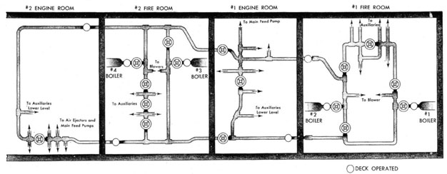
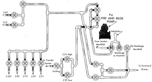
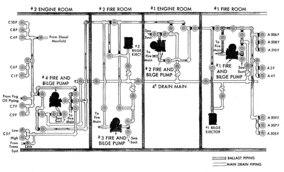
(a) General Discussion.-The auxiliary steam system in both the DD445 and DD692 classes consists of a complete loop through each plant so arranged that both loops can be connected together to form a complete loop throughout the entire engineering spaces. Figure 52 shows the general arrangement of this system for the DD445 class. Details of arrangement differ slightly in the DD692 class from that shown but not sufficiently to warrant an additional drawing. Auxiliary steam is led directly from the boiler steam drums without the use of a desuperheater since the superheater in this boiler is separately fired. The auxiliary steam boiler stop valves are backed up by guarding valves. The guarding valves can be opened only from the fireroom. The auxiliary stop valve can be opened from the deck as well as the fireroom. This arrangement allows the boiler to be cut off the line from the deck but does not allow it to be put on the line unless the guarding valve is opened in the fireroom. This insures that the fireroom watch knows when the boiler is put on the line. Each boiler leads to both sides of the auxiliary steam loop, but they are so arranged that with the boiler stops open Nos. 1 and 3 boilers cannot be cut off the starboard side of the loop and Nos. 2 and 4 boilers cannot be cut off the port side. On the port side of No. 1 fireroom, arranged as shown in figure 52, are the branches to the fireroom auxiliaries on the lower level. The line stop valves here are so arranged that all these branches may be cut in from either direction or so that either half may be used alone. The branches are so arranged that one fuel oil service lump is serviced from each side of the center cutout valve and the emergency feed pump may be furnished with steam from either side. The fire and bilge and the fuel-oil booster pumps are not considered sufficiently important to have parallel leads. In the fireroom, on the port side of the forward loop, is located a cut-out valve which can be operated either from the deck or from the fireroom. On the starboard side a cut-out valve is
provided in the engine room which is also a remote operated valve. The auxiliary steam line leads from both of these valves aft through the engine room and looping across joins together at the valve shown in the center of the engine room. This completes the forward auxiliary steam loop. Branches are led from both sides of this cut-out valve to the main and auxiliary air ejectors and, where two steam lubricating oil pumps are installed, to both lube oil pumps. One main feed pump is served from one side of this valve and the other is served from the opposite side. The other steam pumps on the lower level are served by a line from the starboard side of the cut-out valve. If there is no steam on the starboard side of the loop, this means that the electric condensate pump and the electric main feed booster pump must be operated. In effect the arrangement in the after plant is exactly the same. The three valves, seen in the starboard lead from No. 4 boiler, correspond exactly to the three valves shown on the port side of the loop in No. 1 fireroom. The starboard line cut-out valve is in the fireroom and the port line cut-out valve is in the engine room. The cut-out valve, shown on the starboard side, divides the loop in No. 2 engine room and branches to the air ejectors, and the main feed pumps lead off as shown in the same manner as those discussed in connection with the forward loop. Two cross-connection valves will be noted at the after bulkhead of the No. 1 engine room. They allow the two separate loops to be joined together to form a single loop through the entire plant for parallel operation. Under normal operation the plants should be divided and both of these cross-connection valves closed. Then steam should normally be led to No. 1 engine room down the port side of the forward loop, and to No. 2 engine room down the starboard side of the after loop. This would allow the bulkhead stop valves in both engine rooms to be closed. Minor branches, other than those shown, lead from this system in the fireroom to the 165 p.s.i. steam system and to the steam smothering system.
101
AUXILIARY STEAM SYSTEM
FIG. 52
102
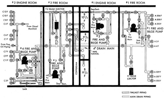
(b) DD692 Class Auxiliary Steam.-The auxiliary steam system in the DD692 class is essentially the same as described above. However, the bulkhead stop valves in each plant are both in the fireroom, and the cross-connection valves are located with the starboard one in No. 1 engine room and the port one in No. 2 fireroom. Branches from both sides of each engine room cut-out (or crossover valve, are led to the lower level so that the steam pumps there can be served from either side of the loop.
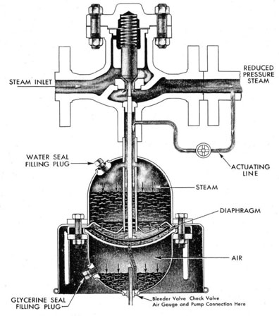
(c) Grove Air Operated Pressure Reducing Valve.-To provide steam under reduced pressure for various services, steam is led from the auxiliary steam line through Grove air-operated reducing valves. The following Grove valves are installed in the ship:
(1) Steam to main and auxiliary air ejectors.-
Two in each engine room; 600/275 p.s.i.
(2) Steam to 165 p.s.i. (or 150 p. 8. i.) line.-
Two in each fireroom; 600/165 p.s.i. (or 150 p.s.i.) auxiliary steam line.
(3) Steam to heating and constant service.-
Two in No. 1 fireroom and two in No. 2 engineroom; 165 (or 150) /40 p.s.i.
(4) Steam to laundry.-One in No. 1 engineroom; 165 (or 150)/100 p.s.i. -
Figure 53 illustrates construction and manner of operation of this valve. A neoprene rubber diaphragm is installed in the center of the dome. The bottom of this diaphragm is separated from the bottom half of the dome by a fixed steel plate. The top of the diaphragm is connected through holes in the shrouding, as shown, to the upper part of the dome. In the lower half of the dome a seal of glycerine is carried, and the upper half of the dome carries a level of water for sealing. A pipe connection is led from the protection plate below the diaphragm to a point which is below the level of the glycerine seal. When air pressure is pumped in, through the air connection, it will exert a pressure downward against the glycerine seal thus forcing glycerine up through this pipe connection into the space between the lower protection plate and the diaphragm. This same pressure will exert a force upward against the diaphragm thus causing the diaphragm to be displaced upward. Since the valve stem of the valve is in contact with this diaphragm, moving the diaphragm upward will cause valve to be forced open and allow steam to pass through the valve seat into the outlet connection. From the outlet connection an actuating line is led
through a valve back to the upper part of the dome in the manner shown in the drawing. Steam at the reduced pressure will then exert a force on the top of the water seal. This force will be transmitted through the water to the top of the diaphragm. When this pressure exceeds the pressure of air in the lower half of the dome, working against the bottom of the diaphragm, the diaphragm will be displaced downward causing the valve to close off. When the reduced steam pressure delivered from the valve then is equal to the air pressure pumped into the bottom half of the dome, the valve should take a stationary position which will pass sufficient steam to maintain that pressure. If the load increases, tending to take more steam away from the valve, the steam pressure will be momentarily reduced. This causes the air pressure to become greater than the steam pressure working down on top of the diaphragm and allow the valve to be opened wider to restore the pressure to normal. If the load is reduced this will cause a momentary increase in steam pressure thereby increasing the pressure on top of the diaphragm above that of the air pressure below it and cause the diaphragm to be displaced downward, reducing steam flow through the valve to again restore the delivered pressure to normal. Thus, theoretically, the valve should deliver a pressure of steam equal to the pressure of air pumped into the lower half of the dome. Since the valve itself has weight and a light spring tending to close it, it is necessary to introduce slightly more air pressure than it is expected to have steam pressure delivered. In general for the higher pressure valves, about 10 p.s.i. additional air pressure is required. If air is pumped into the valve when it is cold it is necessary to pump in slightly less air pressure, since warming up the valve will cause the air pressure to increase slightly. The shroud shown, extending outside the dome from the center flange, appears only on the high pressure valves. This is of copper and is installed to allow for the transmission of heat from the upper half of the dome to the atmosphere and prevent that heat from passing into the lower half. where it may cause an excessive rise in pressure of the air. Each of these valves is set between inlet and outlet cut-out valves. In order to put the Grove valve in operation the discharge valve should first be opened. Then if proper pressure of air is in the dome, the inlet valve should be opened slowly. allowing the valve to heat up. The valve in the actuating line must he open. It will he difficult
103
GROVE REDUCING VALVE
FIG. 53
to get these valves on the line unless some steam is being bled away from the discharge, so it is desirable if possible to have some steam leaving the valve when cutting in. If care is taken to properly warm up these valves and lo put them on the line slowly, no trouble should be encountered with their operation. The lower seal should always be of glycerine. The upper seal is of water, and condensation of the steam in the upper part of the dome should be sufficient so that it will never require refilling.
2. FUEL OIL SYSTEMS
(a) Fuel Oil Service Systems.-For each plant there are two fuel oil tanks designated as fuel oil service tanks, from which the oil furnished to the fuel oil burners is pumped. These two tanks are the after center line tanks of the forward group. i.e.. A2F and A3F, and the forward center line tanks of the after group i. e., C1F and C4F. Oil is pumped through the fuel oil service pumps and discharged through the fuel oil heaters and strainer to the boilers. The construction of the
104
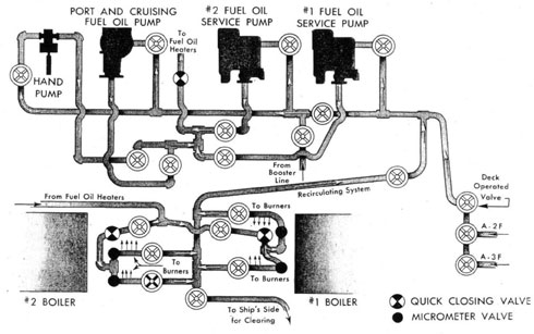
fuel oil service pump is similar to that of the lubricating oil service pump, except that the pump is of smaller capacity and is designed to deliver a maximum operating pressure of 350 p.s.i. The turbine end and the governor are the same as those on the lubricating oil pumps, with the governor setting being 1,141 r.p.m. Governor travel is the same as on the lubricating oil pumps, namely three-eighth inch. All fuel oil service pumps are steam-driven. There are two fuel oil service pumps installed in each fireroom, each taking suction from its own group of service tanks through a suction line common with the other pump in the same space. In addition to these pumps, on early ships of the DD445 class, a port and cruising fuel oil pump is also installed for port use. It is probable that port-use fuel oil service pumps will be installed in the remaining ships of the DD445 class and in all ships of the DD692 class as a post-war project. This pump is a vertical variable stroke pump built on the principle of the A end of a Waterbury speed gear, and has a maximum capacity of 10 gallons per minute at 350 p.s.i. The main fuel oil pumps are controlled by Leslie constant pressure pump governors, the construction of which is exactly similar to the one previously described in the discussion of the lubricating oil pumps. The diaphragms and springs are designed to take care of the higher discharge pressure of the pump but the operation and adjustments of the governor are the same. There is one fuel oil heater in each fireroom consisting of four units, which can be operated either singly or with any number of units in parallel. Steam for this heater comes from the auxiliary steam line, and the drain passes through a combined inspection tank and trap, to insure condensation of all steam admitted to the heater (thus obtaining maximum heat transfer efficiency) and to note fuel oil contamination of the drains. A meter is fitted in the line before the heater, and after the heater the oil passes through a double-barrelled strainer, before going to the boiler fronts. The fuel oil service suction manifold is located on the forward bulkhead of the forward fireroom. It consists of three valves, the left-hand one of which is a cut-out valve for the entire manifold. The center valve is for suction from tank A2F and the right-hand one for suction from tank A3F. The suction line leads from this manifold down the port side and through a cut-out valve. After this cut-out valve, branches lead off (fig. 54) to both fuel oil service pumps, the
port-and-cruising fuel oil service pump. and the hand fuel oil service pump. A line leads from the fuel oil booster system into the suction line between the two fuel oil service pumps. This allows the booster pump to put a pressure on the suctions of the service pumps if necessary. Each pump is provided with its own suction valve at the pump. Between the port-and-cruising pump and No. 2 fuel oil service pump is the discharge manifold which carries the discharge valves from all four pumps. They are arranged as shown in the sketch, and discharge overhead through a quick-closing valve to the heaters. This quick-closing valve, directly after the pump discharge manifold, is rigged with a wire pull so that it can be closed from the deck and cut off oil from the boilers in case of emergency. The discharge line leads to the heater, with a bypass around each element, and beyond the heater joins into a single line again to go through the strainer. From there it leads between the boilers and branches off to two cut-out valves, each of which leads to one boiler. Each line passes through another quick closing valve before going to the burner manifolds. This valve is rigged to be operated by a wire pull from the upper grating between the boilers, so that in case of low water or other casualty it can be closed by the check man to cut off oil from the boiler. After passing through this valve each line branches to both the saturated and superheater burner manifolds. A micrometer valve is installed in the line before each manifold by means of which the oil pressure to the burners themselves may be adjusted. This is necessary in order that the fuel oil service pump may carry a constant pressure and yet deliver different pressures to the two manifolds, as is most frequently the case. In order to allow oil to pass through the heater to heat up the oil to proper temperature before lighting off, recirculating valves are provided at the base of each burner manifold. These valves will lead oil directly from the manifold back to the suction line of the fuel oil service pumps. It should be noted in this connection that the oil should never be heated above the temperature corresponding to 150 S. S. U. or excessive wear on the pump rotors and barrel will occur due to inadequate lubrication. From this recirculating system is also led a line to the ships side to allow oil to be pumped overboard from the system in case water has gotten into the system. This "clearing" line is furnished in order to clear this water out before taking
105
FUEL OIL SERVICE SYSTEM - #1 FIRE ROOM
FIG. 54
suction on another tank, and to prevent pumping it into the boiler furnace. The sketch of the after system shows it to be exactly similar to the forward system in general arrangement. However, the service suction manifold is in the engineroom in this case. The tanks used are the centerline tanks in the after group, C1F and C4F. The recirculating line, instead of joining the suction line between the tanks and the line cut-out, enters after the line cut-out, and the booster connection to the service suction line enters between No. 3 service pump and the port-and-cruising service pump. Otherwise the system is the same, including the recirculating system and clearing line. Where no port-and-cruising pump is installed the foundation and fittings have been retained to provide for future installation, when production will permit. With the exception of the service tank numbers, the fuel oil service system of the DD692 class is the same as for the DD445 class. The forward tanks on the DD692 class are A3F and A4F and the after tanks are C1F and C6F.
DD692 class (long hulls) ships have three tanks located between the forward engineroom and the after fireroom. A connection from the manifold to the transfer system in the forward engineroom has been provided to permit using the center line tank, B-9 1/4 F, as an emergency fuel oil service tank.
The Bureau recommends the following fuel oil service tank procedure:
(1) Take suction from one service tank of each system at a time.
(2) Maintain the fuel oil service tank levels between 95 and 50 per cent, to insure an adequate gravity head.
(3) Fill the stand-by service tank of each system shortly after shifting suction to the adjacent service tank, for settling-out water and sediment.
(4) Prior to taking suction from a stand-by service tank take a thief-sample if practicable; and take a low suction for a short interval and
106
FUEL OIL SERVICE SYSTEM - AFTER GROUP
FIG. 55
discharge to the contaminated oil tank or overboard, as operating conditions permit.
Satisfactory thief samplers can be manufactured aboard ship. The Bureau's latest plan of one suitable for sounding-tube use is BuShips Plan S5501-64052-SK of 16 August 1943 (Sounding Tube Oil Samplers). The oil samples can be inspected visually in a glass bottle, or centrifuged if a centrifuge is available.
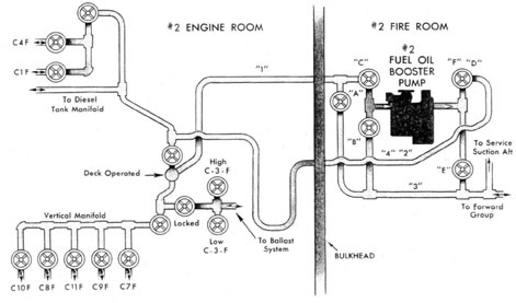
(b) The Fuel Oil Transfer System DD445 Class.-The only pump involved in the transfer system is the fuel oil booster and transfer pump. This pump is constructed in the same manner as the fuel oil service pump, except that it is designed to operate at a lower pressure with a higher capacity than the service pump. The pump is rated to discharge 100 gallons per minute at a pressure of 100 p.s.i. Under normal operation (transferring oil) the discharge pressure will not be this high due to the lack of a head to pump against, and the capacity will be controlled by the speed of the pump. The booster pump is connected
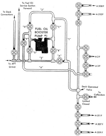
to the forward fuel oil tanks, as shown in figure 56, by three manifolds located on the forward bulkhead of the forward fireroom. The center manifold is for the fuel oil service tanks A2F and A3F. This is a four-valve manifold, the end valves on the manifold being cut-out valves for the manifold. The left-hand space valve is the cut-out for suction from the tanks and the right-hand valve is the cut-out valve for discharge to the tanks. The manifold on the port side is a three-valve manifold and connects to the port wing tanks A508F and A510F. The right-hand valve is the manifold cut-out valve. The manifold on the starboard side is a four-valve manifold and connects to tanks A511F, A507F and A509F, in that order. The left-hand valve of this manifold is the manifold cut-out valve. These manifolds are all joined together by a common line as shown and lead to the No. 1 fuel oil booster pump through a cut-out valve which may be operated either from the fireroom or from the deck. In addition, a single valve branches from the
107
FUEL OIL TRANSFER SYSTEM
FORWARD GROUP 445 CLASS
FIG. 56
common line and connects to the cofferdam. This valve is locked closed. The line leading to the fuel oil booster pump passes through another cutout valve and then leads on past the booster pump to cross-connect with the after transfer system. The suction manifold of the booster pump consists of two valves which have been lettered B and C for convenience in explanation. The additional cutout valve shown has been lettered A. The discharge manifold of the pump consists of three valves which have been lettered D, E, and F. Valves B and E are connected to the cross-connection line as shown. Valve F is connected to the discharge cut-out valve of the service tank
manifold. Line 1 leads as shown to the discharge side of valve C and into line 2 which joins valves D, and C. To take a suction from any tank of the forward group and discharge into the fuel oil service tanks, valve A is closed and suction drawn through line 1 and valve C. Discharge is led through valve F to the service tank manifold. The service tanks are the only ones in the forward group into which oil can be discharged when taking suction from tanks in the forward group. To take suction from the forward tanks and discharge aft, suction is taken through valve C and the oil discharged through valve E. To take suction from the after group and discharge forward
108
FUEL OIL TRANSFER SYSTEM
AFT GROUP - 445 CLASS
FIG. 57
the oil passes through line 3 and valve B, discharging through valve D and lines 2 and 1 to the tank manifold required with valve A remaining closed. From the crossconnection line a branch is led into the fuel oil service pump suction line, by means of which oil can be pumped into the crossconnection and then into the service pump suction when necessary. For the after pump to take suction from or discharge into the forward tanks the crossconnection can be opened by opening valve A. The only time valve A should have to be open is when taking suction from or discharging into the forward tanks with the after booster pump. The manifolds for the after group of tanks are located on the after bulkhead of No. 2 engineroom. The manifold for the service tanks is a three-valve manifold, the right-hand valve of which is the manifold cut-out valve. There is a single six-valve manifold for the other five tanks in the after group, the lower one of which is the manifold cut-out valve. The after service tanks are C1F and C4F and the storage tanks aft are C10F. C8F, C11F, C9F, and C7F. These two manifolds are joined as shown by a line
containing two cut-out valves one of which can be operated from the deck as well as from the engine room. The deck operated cut-out valve is connected to the suction manifold of the after booster pump in No. 2 fireroom. Branching from the manifold line as shown in the contaminated oil tank (C3F) manifold which has two valves, one for high suction and one for low suction. A cut-out valve to this manifold from the transfer system is provided which should he kept locked unless in use. The suction manifold of the booster pump consists of two valves marked B and C. and the discharge manifold also of two valves marked E and FD. Valve A is a bypass valve and serves the same purpose as valve A in the forward group. In order to take a suction from the after tanks and discharge into the after service tanks the oil is led from the storage tank manifold through the deck operated valve to the suction of the booster pump through valve C. It is discharged through valve FD and line 4 and 2 up to the service tank manifold with the cut-out valve in the manifold crossconnection line closed to prevent the discharge from going back into the suction. As in
109
the forward system, a suction cannot be taken from the after tanks and discharge into any tanks aft except the service tanks. To take a suction from aft and discharge to the forward system through the crossconnection line the suction is drawn through line 1 and valve C and discharged through valve E to the crossconnection line. To take a suction from the forward group and discharge to the after group the suction is led through line 3 and valve B and discharged through valve FD to the manifold crossconnection. When using the forward booster pump on the after system, either taking suction or discharging, the bypass valve A will bypass the after pump and connect the forward pump directly with the tanks. Thus valve A need only be used when using the forward pump on the after system. From the manifold crossconnection in this after system a branch is led off to crossconnect the diesel oil tank manifold with this system.
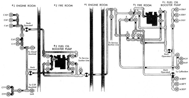
(c) Fuel Oil Transfer System-DD692 Class. The arrangement of the fuel oil transfer system differs considerably from that of the DD445 class. Figure 58 is a schematic representation of this system. It will be noted that the manifolds connecting to the forward fuel oil tanks are not all connected to a single line as in the DD445 class. The manifold for the starboard tanks is entirely separate from those of the fuel oil service tanks and the port storage tanks. The suction manifold of No. 1 fuel oil booster pump consists of the valves lettered A and B. The discharge manifold of this same pump consists of the valves lettered C, D, K and F. Valves G, H, and I can be termed the Cross-Connection Manifold. This system is arranged so that in addition to being able to transfer oil from the forward group of fuel oil tanks to the after group of fuel oil tanks or vice versa, and from any fuel oil tank to the fuel oil service tanks, it is possible to transfer oil from one side of the ship to the other in the same group. To take suction from the port group of tanks forward and from the fuel oil service tanks it is necessary to use valve A of the suction manifold. Taking suction from here, oil may be transferred either to the after system through valve C, or to the starboard tanks forward through valve F. To transfer oil from the starboard tanks forward to the port side it is necessary to take suction through valves H and B and discharge through valve B of the discharge manifold. A separate line is provided leading from the discharge manifold and its valve E, directly to the
service tank manifold. which allows for the transfer of oil from any storage tank to the fuel oil service tanks. In order to use No. 1 fuel oil booster pump for transfer of oil from the forward group of tanks to the after group, the discharge can be led through valve C of the pump discharge manifold. This will put pressure on the cross-connection line, and in order to lead oil to the after tanks, valve O in the after fireroom must be open and the valves N or P, depending on which tanks are to be used. To take suction with No. 1 fuel oil booster pump from the after tanks, it is necessary to open valves G and B. This will open the cross-connection line to the suction of the forward pump, and opening the same valves previously mentioned in the after fireroom will connect the cross-connection line with whichever tank in the after group is desired. The discharge in this case can be led to the forward tanks either through valves B or F. In the after fireroom valves J, K, and L comprise the suction manifold, and M, N, O, and P, the discharge manifold. Valve M is a pump discharge cut-out valve. It is installed in this pump to prevent pressure from the cross-connection line from backing into the pump from the discharge manifold. If this were allowed to occur when No. 2 pump is not in operation the pump would operate backward. This valve M should never be open unless No. 2 pump is in operation. The after manifolds are arranged to allow transfer of oil from one side to the other and to the fuel oil service tanks, as in the forward system. To take suction from the port side valve L is used, and to discharge to the starboard side valve P should be opened. To take suction from the starboard side valve L is opened and the discharge to the port side is led through valve N. To discharge to the after service manifold from any tank a separate line is not provided. However, by closing the proper service tank manifold cut-out valve oil can be discharged to the service tanks from either side of the ship. Inspection of the after manifold arrangement will make this apparent. If the after pump is used to take suction from the forward system, valve K must be opened and in the cross-connection manifold in the forward fireroom valve G should be opened. This opens the cross-connection manifold and valve H or I will allow suction from the forward tanks. To discharge from the after pump into the forward system, valve O must be opened and valve G in the cross-connection manifold will allow distribution
110
FUEL OIL TRANSFER SYSTEM
692 CLASS (SHORT HULL)
FIG. 58
111
FUEL OIL TRANSFER SYSTEM
DD 692 CLASS (LONG HULL)
FIG. 58A
112
FUEL OIL TANK DRAIN SYSTEM
FORWARD GROUP - 445 CLASS
Fig. 59
through valve H or I to the forward tanks. Branches from the cross-connection line to the actually installed in the forward fireroom, is a service suction system appear in each fireroom as in the DD445 class. Not shown on figure 58 but riser from the cross-connection line which leads to the two deck connections. Deck operated valves, and the connections to the diesel tank manifold, the contaminated manifold and the cofferdam, appear as indicated.
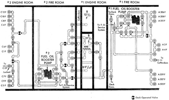
The DD692 class (long hull) have three tanks located athwartships between the forward engine room and the after fire room. Manifolds located in the after fire room connect these tanks to the fuel oil transfer and drainage systems. A manifold located in the forward engine room and connected to the transfer system permits using the center line tank as an emergency service tank.
(d) The Fuel Oil Tank Drain and Ballast System DD 445 Class.-In order to completely drain any fuel oil tank as well as to maintain the ship in ballast and in a stable condition when fuel oil is expended from the tanks thus reducing the ship's displacement, it is necessary to provide a system to
fill empty fuel oil tanks with sea water and drain them of oil. To accomplish this, separate manifolds are provided which connect to the fuel oil tanks and to two of the fire and bilge pumps. The manifolds to the forward tanks connect to No. 1 fire and bilge pump and the manifolds to the after tanks connect to No. 4 fire and bilge pump. The ballast system forward has two manifolds located on the forward bulkhead of No. 1 fireroom. The six-valve manifold leads to all tanks forward except the service tanks, and has no cut-out valve on it. The manifold for the service tanks is separate, with a valve for each service tank and a cutout valve. Both manifolds lead into a common line which acts as a discharge as well as a suction line. This line leads to No. 1 fire and bilge pump suction manifold through a valve and also branches off as shown through a cut-out valve, to the crossconnection valve and to the fire and bilge pump discharge manifold. The crossconnection valve leads through the plant to the after system. The fire and bilge pump can take suction from the sea and discharge through the discharge valve and the cut-out valve into the manifold line to fill any tank.
113
DD445 CLASS
Recommended sequence table for emptying fuel oil tanks
FORWARD GROUP
AFTER GROUP
Time
Shift steaming suction to-
Take transfer suction from-
Transfer to-
Time
Shift steaming suction to-
Take transfer suction from-
Transfer to-
A-2F
C-1F
When A-2F is down 4,500 gallons.
A-3F
A-4V
A-2F
When C-1F is down 2,500 gallons.
C-4F
C-3F
C-1F
When A-3F is down 9,000 gallons.
A-2F
A-507F A-508F
A-3F
When C-4F is down 8,500
C-1F
C-10F C11-F
C-4F
When A-2F is down 6,000 gallons.
A-3F
A-507F A-508F
A-2F
When C-1F is down 7,000 gallons.
C-4F
C-10F C-11F
C-1F
BALLAST A-507F AND A-508A
BALLAST C-10F AND C-11F
When A-SF is down 9,000 gallons.
A-2F
A-510F A-511F
A-3F
When C-4F is down 8,500 gallons.
C-1F
C-8F C-9F
C-4F
BALLAST A-510F AND A-511F
When A-2F is down 5,000 gallons.
A-3F
A-509F
A-2F
When C-1F is down 7,000 gallons.
C-4F
C-8F C-9F
C1F
When A-3F is down 6,000 gallons.
A-2F
A-509F
A-3F
When C-4F is down 8,500 gallons.
C-1F
C-8F C-9F
C-4F
BALLAST A-509F
BALLAST C-8F AND C-9F
When A-2F is down 4,000 gallons.
A-3F
C-7F
A-2F
When C-1F is down 1,600 gallons.
C-4F
C-7F
C-1F
BALLAST-C-7F
NOTE-When it is known that the Diesel oil or Diol will have to he burned, mix these oils with at least an equal quantity of fuel oil. Extreme caution must, be exercised to prevent contamination of Diesel or Diol tanks with black oil when transferring these oils. Do not ballast C-501F or C-6F.
114
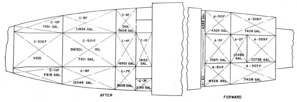
DD445 CLASS
FUEL OIL TANK ARRANGEMENT
115
DD692 CLASS (SHORT HULL)
Recommended sequence table for emptying fuel oil tanks
FORWARD GROUP
AFTER GROUP
Time
Shift steaming suction to-
Take transfer suction from-
Transfer to-
Time
Shift steaming suction to-
Take transfer suction from-
Transfer to-
A-3F
C-1F
When A-3F is down 6,000 gallons.
A-4F
A-5VF C-5F
A-3F
When C-1F is down 7,000 gallons.
C-6F
C-9F C-10F
C-1F
When A-4F is down 8,000 gallons.
A-3F
A-505F A-506F
A-4F
When C-6F is down 8,000 gallons.
C-1F
C-9F C-10F
C-6F
BALLAST A-505F AND A-506F
When A-3F is down 9,500 gallons.
A-4F
A-507F A-508F
A-3F
When C-1F is down 7,000 gallons.
C-6F
C-9F C-10F
C-1F
BALLAST A-507F AND A-508F
When A-4F is down 8,100 gallons.
A-3F
A-509F A-510F
A-4F
When C-6F is down 9,000 gallons.
C-1F
C-9F C-10F
C-6F
BALLAST A-509F AND A-510F
BALLAST C-9F AND C-10F
When A-3F is down 8,000 gallons.
A-4F
C-7F C-8F
A-3F
When C-1F is down 6,000 gallons.
C-6F
C-7F C-8F
C-1F
BALLAST C-7F AND C-8F
When C-6F is down 3,000 gallons.
C-1F
C-4F
C-6SF
BALLAST C-4F
NOTE-When it is known that the Diesel oil or Diol will have to he burned, mix these oils with at least an equal quantity of fuel oil. Extreme caution must, be exercised to prevent contamination of Diesel or Diol tanks with black oil when transferring these oils. Do not ballast C-501F or C-502F.
116
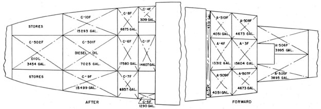
DD 692 CLASS (SHORT HULL)
FUEL OIL TANK ARRANGEMENT
117
DD692 CLASS (LONG HULL) DESTROYERS
Recommended sequence table for emptying fuel oil tanks
FORWARD GROUP
AFTER GROUP
Time
Shift steaming suction to-
Take transfer suction from-
Transfer to-
Time
Shift steaming suction to-
Take transfer suction from-
Transfer to-
A-3F
C-1F
When A-3F is down 6,000 gallons.
A-4F
A-5VF C-5F
A-3F
When C-1F is down 6,000 gallons.
C-6F
B-9 3/4VF
C-1F
When A-4F is down 8,000 gallons.
A-3F
A-505F A-506F
A-4F
When C-6F is down 8,000 gallons.
C-1F
C-11F C-12F
C-6F
BALLAST A-505F AND A-506F
When A-3F is down 9,500 gallons.
A-4F
A-507F A-508F
A-3F
When C-1F is down 8,000 gallons.
C-6F
C-11F C-12F
C-1F
BALLAST A-507F AND A-506F
When A-4F is down 8,100 gallons.
A-3F
A-509F A-510F
A-4F
When C-6F is down 5,500 gallons
C-1F
C-1IF C-12F
C-6F
BALLAST A-509F AND A-510F
DO NOT BALLAST C-11F AND C-12F
When A-3F is down 7,500 gallons.
A-4F
C-9F C-10F
A-3F
When C-1F is down 8,000 gallons.
C-6F
C-9F C-10F
C-1F
When A-4F is down 7,500 gallons.
A-3F
C-9F C10F
A-4F
When C-6F is down 8,000 gallons.
C-1F
C-9F C-10F
C-6F
BALLAST C-9F AND C-10F
When A-3F is down 7,000 gallons.
A-4F
C-7F C-8F
A-3F
When C-1F is down 7,000 gallons.
C-6F
C-7F C-8F
C-1F
BALLAST C-7F AND C-8F -
When C-6F is down 3,000 gallons.
C-1F
C-4F
C-6F
BALLAST C-4F
When A-4F is down 5,500 gallons.
A-3F
B-9 1/2F B-10 1/2F
A-4F
When C-1F is down 5,500 gallons.
C-6F
B-9 1/2F B-10 1/2F
C-1F
When A-3F is down 5,500 gallons.
A-4F
B-9 1/2F B-10 1/2F
A-3F
When C-6F is down 5,500 gallons.
C-1F
B-9 1/2F B-10 1/2F
C-6F
BALLAST B-9 1/2F AND B-10 1/2F
When A-4F is down 8,500 gallons.
A-3F
B-9 1/4F
A-4F
When C-1F is down 8,500 gallons.
C-6F
B-9 1/4F
C-1F
DO NOT BALLAST B-9 1/4F
NOTE-When it is known that the Diesel oil or Diol will have to he burned, mix these oils with at least an equal quantity of fuel oil. Extreme caution must, be exercised to prevent contamination of Diesel or Diol tanks with black oil when transferring these oils. Do not ballast C-501F or C-502F.
118
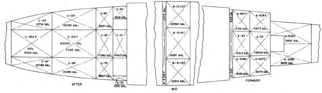
DD692 CLASS (LONG HULL)
FUEL OIL TANK ARRANGEMENT
119
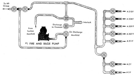
It can also take suction from any tank through the fire and bilge pump suction valve and discharge either overboard directly from the pump or into the after system through the cross-connection valve. From the after system the oil can be put into the contaminated tank to allow separation of the water from it. The manifolds are provided with sight drain valves by which it can be seen whether the discharge is clear water or contaminated. In the latter case it would be desirable to strip the tank into the contaminated tank. The entire after system is in the after engine room. The after system has two manifolds also, one for the service tanks with a cut-out valve, and one for the storage tanks without a cut-out valve. These join together and lead to one valve of a two-valve manifold. The other valve of this manifold leads to the contaminated tank manifold. From these two valves a line leads to the fire and bilge pump suction valve. The discharge from the fire and bilge pump leads from its valve to a three-valve manifold. One valve of this manifold leads to the common line from the tank manifolds between the manifolds and the two-valve manifold previously mentioned. Another valve leads to the contaminated tank line as shown, and the third leads forward and joins the line from the forward system, making the cross-connection. Through this last manifold suction can be taken from the sea and discharged into any tank aft, into the contaminated tank or into the cross-connection to the forward system. We can also take suction from any after tank and discharge into the contaminated tank or tip to the forward system, or we can take suction from the contaminated tank and discharge into the tanks of either system. Note that while it is possible to discharge into either system with either pump this can only be done when taking suction from the other system. Also it is possible to take suction with a pump from the other system only when discharging directly overboard from the fire and bilge pump. The valve of the fire and bilge pump suction manifold, which connects to the ballast system. is so yoked to the pump discharge valve to the fire main that neither one can be opened unless the other is closed. This will prevent the pump from taking suction from the ballast system and discharging into the fire main. The only two pumps connected into the system in this manner are No. 1 fire and bilge pump in No. 1 fire room, and No. 4 fire and bilge pump in No. 2 engine room,
and these are the only fire and bilge pump on which the above interlocking yoke appears. The after system has a connection to the diesel fuel oil manifold, to provide for stripping or ballasting these tanks in the same manner as the fuel oil tanks.
(e) Fuel Oil Tank Drain and Ballast System (DD692 Class).-This system in the DD692 class has been revised from the initial installation which was similar to the DD445 class. The revised system permits pumping the forward group of tanks with Nos. 1 and 2 fire-and-bilge pumps (the midships tanks of long-hull ships being considered part of this group) and pumping the after group of tanks with Nos. 3 and 4 fire-and-bilge pumps. A cross-connection is provided between the forward and after systems.
The drainage eductors are connected to the ballast system in their respective spaces to provide an alternate emergency unwatering facility in the event one or more of the fire-and-bilge pumps is inoperative or in use for another service. A swing-check valve is installed in the piping connecting the eductor to the main drain system to prevent contaminated water or fuel oil from entering this system.
The interlocks previously provided between the fuel oil tank drain suction valve and the fire-main discharge valve have been omitted in this revised arrangement. Warning tags have been provided in lieu thereof.
The diagrammatic arrangement of this system in the DD692 class (short hull and long hull) are shown in figures 61 and 61A, respectively.
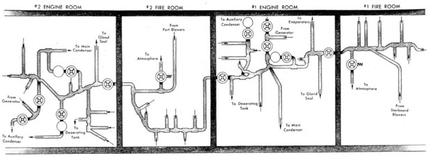
3. THE AUXILIARY EXHAUST SYSTEM
(a) General Discussion.-This system consists of a continuous run of piping from the forward fireroom through the machinery spaces to the after engine room. The exhaust from all auxiliary steam equipment leads into this line. In each fireroom there is a spring-operated valve which can connect the auxiliary exhaust line to the atmosphere via the escape piping. In each engine room a branch leads up to the deaerating feed tank through a weight-loaded check valve to furnish steam for operation of the deaerating feed tank, Two Swartwout unloading valves are provided in each engine room, one discharging to the main con-denser and one to the auxiliary condenser. There are cut-out valves in the line at the forward and after bulkheads of the forward engine room and one at the forward bulkhead of the after engine
120
FUEL OIL TANK DRAIN SYSTEM
AFTER GROUP - 445 CLASS
FIG. 60
121
FUEL OIL TANK BALLAST SYSTEM
DD 692 CLASS (SHORT HULL)
FIG. 61
122
FUEL OIL TANK BALLAST SYSTEM
DD 692 CLASS (LONG HULL)
FIG. 61A
670586-46-9
123
AUXILIARY EXHAUST
FIG. 62
124
room. The valve at the after bulkhead of the forward engine room divides the system.
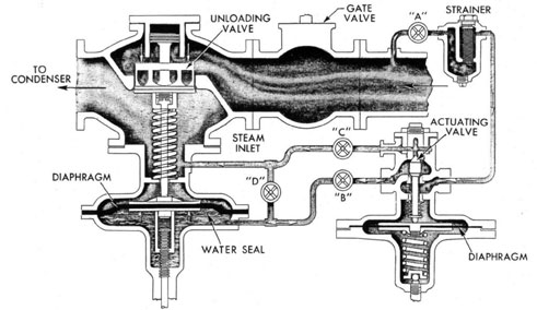
(b) The Swartwout Unloading Valve.-This equipment consists of the unloading valve itself, the
actuating valve and their connecting piping and valves. Steam inlet is to the bottom, or under the seat, of the unloading valve. The valve is diaphragm-operated. The actuating valve is also diaphragm-operated, and steam pressure is led to the top of this diaphragm from the steam inlet
side of the unloading valve. The actuating valve is a double-seated valve, one side of which is
closed when the other side is open. When pressure in the auxiliary exhaust line is less than the
set pressure the upper seat is closed and the lower seat is open. Steam pressure led from the
line acts on the diaphragm and also passes through the valve and then to the bottom of the
unloading valve diaphragm through valve E. This pressure acting on the unloading valve
diaphragm holds the unloading valve closed. When pressure in the Auxiliary exhaust line
exceeds the set pressure, the diaphragm in the actuating valve is displaced, closing the lower
seat of the actuating valve and opening the upper seat. It is apparent that we then have a direct
connection from below the unloading valve diaphragm, through the actuating valve, to the top of
the unloading valve diaphragm. Pressure on the diaphragm being equalized, the exhaust line
pressure working on the unloading valve disc forces it open and dumps steam into the main or
auxiliary condenser. The pressure at which the valve unloads can be adjusted by changing the
spring tension against the actuating valve diaphragm. A stem is inserted in the unloading valve
below the diaphragm to allow for manual operation. When fully withdrawn this stein has a
mushroom which catches a yoke and pulls down the diaphragm to open the valve. Driving the
stem fully in causes it to make contact with the diaphragm, forcing the valve closed. In the
mid-position the valve is free to operate automatically. Before taking the valve off automatic
operation, it is necessary to open the by-pass valve D to equalize the pressure on both sides of
the unloading valve diaphragm.
Note: If the valve has failed to unload at the set pressure, adjusting the actuating valve will not
make it do so. Opening the unloading valve manually without disturbing the actuating valve
setting will probably free the unloading valve. Then. when placed back on automatic the valve
should operate normally.
4. DRAIN SYSTEMS
(a) General Discussion.- There are three drain systems installed in these ships; namely, the
high pressure drains, the low pressure drains and the contaminated drains.
(b) High-Pressure Drain System.-The high-pressure drain system consists of a single header
in each plant which collects the drains from all high-pleasure lines and leads them into the
deaerating tank. The cross-connection is provided between the two systems so that it is
possible, under auxiliary operation, to drain the entire plant into one deaerating tank. All the
drains leading into this system lead through Yarway impulse traps. These, are constant flow steam
traps and their action will be discussed shortly. Since these are constant flow traps the high-pressure drain system must operate under pressure. The discharge from this system leads only
into the deaerating tank, and consists entirely of steam. A condition may occur, when securing
or when warming up, that will cause the deaerating tank to overheat somewhat because of
excessive high-pressure drains entering the deaerating tank. In this case, in order to reduce the
deaerating tank temperature it will be necessary to run down some water from the base of the
deaerating tank into the main condenser and recirculate it back to the tank through the
condensate system. This will cool the water and allow for a greater volume of water to be passed
through the tank in order to reduce the tank temperature. When securing, it may be desirable to
keep two deaerating tanks in operation for longer than is necessary in order to take care of
excessive high-pressure drains.
(c) Yarway Impulse Steam Trap.-The Yarway impulse steam trap is shown in Figure 63A. This
is a constant flow trap and allows a continuous flow of steam into the high-pressure drain line
as long as its cut-out valves are open. As shown in Figure 63A the valve disc is a piston type
disc With a flange at its top and a "control orifice" drilled through it. The piston valve works up
and down within a cylinder which is machined with a reverse taper and which is, at its smallest
point. the same size as the flange on the valve disc. The position of this cylinder is factory-adjusted so that. with the valve closed, a specific clearance between the flange and cylinder
walls is maintained. The area of the control orifice is slightly greater than that of the space
between the cylinder and flange. Due to the larger area of the control
125
SWARTOUT UNLOADING VAVLE
FIG. 63
126
YARWAY IMPULSE STEAM TRAP
FIG. 63a
127
orifice, condensate flowing from the steam line when warming up will flow through it faster than it will flow past the flange. This will cause a reduction pressure within the cylinder. When this pressure is reduced to 86 percent of the inlet pressure or less, the force on top of the valve disc is less than the force below the flange and the valve will be forced open. allowing a full flow of condensate through the valve (approximately 1,400 lb. per hr. for a three-fourths inch trap). As the line warms up the temperature of the condensate flowing through the trap increases and as it approaches the temperature of saturated steam the condensate flowing through the control orifice will start to flash into steam (due to the large drop in pressure through the orifice). This steam having much greater volume than the same quantity of condensate will cause the control orifice to become "choked" up and thereby reduce the flow of condensate. This will cause the pressure within the cylinder to be built up until it is greater than 86 percent of the inlet pressure and the trap will be closed due to the greater area of the top of the disc. With the trap closed, hot condensate or steam will continually flow through the control orifice, discharging into the high-pressure drain line. With 600 p.s.i. pressure to a three-fourths inch trap this amount of constant flow will be approximately 60 lb. per hour. Should a shot of cool condensate enter the trap at any time the same action will occur to drain off the condensate, with the valve closing when the condensate temperature is approximately 30 degrees F. less than the steam temperature. The stein seen attached to the cylinder can be used to raise the cylinder, catching the flange at the base of the taper and manually lifting the valve disc for the purpose of blowing through it to clean off the seat. The lock nut shown is pinned in place. It has been adjusted at the factory to provide the proper clearance between the cylinder and valve flange and should not be moved. The baffle shown shrouding the cylinder and valve disc is placed there to prevent direct impingement of the steam on the cylinder or disc and in addition, provide a guard against possible jet action on the flange. The large flange on the top of the valve is removable and taking it off will remove entirely the cylinder and valve disc, exposing the seat. This will allow for cleaning of the cylinder and grinding of the seat when necessary. The cylinders and disc are interchangeable and in case of damage can be replaced as a unit.
(d) Low-Pressure Drain System.- The low-pressure drain system consists of a header extending through each plant which collects water from the funnel drains at atmospheric pressure and leads it off into the low-pressure drain tank. There are a few drains which enter this system that do not pass through a funnel namely, the generator gland drains, forced draft blower gland drains (DD445 class) and the after- and gland-seal condenser drains. A cross-connection is provided between the two plants to allow for drainage of all low-pressure drains into either of the low-pressure drain tanks. Attached to the low-pressure drain tank is a float-operated valve, and branches lead from this valve to both the main and auxiliary condensers. When the level in the low-pressure drain tank rises the float causes the float-operated valve to lift and connect whichever condenser may be in use to the low-pressure drain tank. The vacuum in the condenser will then drag water from the tank until the level drops to a point where the valve is again closed. Cut-out valves are located in the branches of the two condensers A frequent casualty in securing is in shifting the low-pressure drain tank from the main condenser to the auxiliary condenser. The valve to the auxiliary condenser is opened but that to the main condenser is not closed, and when the vacuum is dropped on the main condenser it is also lost on the auxiliary condenser. These two valves should never be opened at the same time. Vents lead from this low-pressure drain tank to the auxiliary condenser and auxiliary air ejector, as well as into the main turbine gland seal exhaust line. The vent line to the gland seal exhaust line should only he used when that system is in operation, otherwise the tank should be vented to the auxiliary condenser or the auxiliary air ejector.
(e) Contaminated Drains.-The contaminated drain system collects the drains from all those services which may, due to leaks, allow oil to get into the system. These drains lead from the fuel oil tank heating coils, the lubricating oil storage and settling tank heating coils and the fuel oil heaters in the firerooms. These are all collected by a single header and must all pass through an inspection tank on the upper level in the engineroom. A cross-connection is also provided to allow for paralleling this system on one inspection tank. From the inspection tank the drains can be led either to the bilge, in case they are contaminated, to the low-pressure drain tank,
128
or to the deaerating tank. The drains from the fuel oil heaters of the fireroom pass through a drain trap and inspection tank before entering the contaminated drain header. This provides for quick determination as to whether fuel oil heaters are leaking and also allows for maintenance of the seal on the fuel oil heaters. Under most conditions of operation, except in cold waters, the only drains entering the contaminated drain system will be from the fuel oil heaters. At low rates of operation insufficient steam to the fuel oil heaters will not allow for drainage through the inspection tank in the engine room. The water level would have to rise into the heaters to allow for gravity drainage through the inspection tank. Therefore, at these low rates it may be necessary to periodically dump the trap to the bilge in order
to prevent the water level from rising into the heaters. This will occasion a certain loss in water but will do away with the excessive carbon formation in the heaters caused when shots of high-pressure steam are used to force drainage. As previously noted, drains from these inspection tanks may go to the deaerating tank, but in this case the pressure in the system must be at least as great as that in the deaerating tank. Therefore, until the pressure is sufficiently great the inspection tank must be drained to the low-pressure drain tank. Under normal operation this drain system and both of the other drain systems would be operated with the cross-connection valves at the after bulkhead of No. 1 engine room closed, to divide the plant.