The expansion system of the steam cycle is that part of the cycle in which steam is led from the boilers to the main turbines, and expanded in those turbines to remove the heat energy stored up in the steam and transform that energy into mechanical energy of rotation. This energy is then transmitted through the main reduction gears and line shafting to the propellers.
2. MAIN STEAM SYSTEM
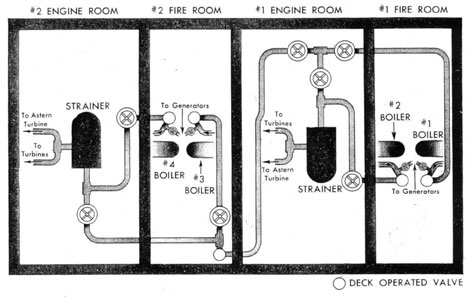
The main steam system is the piping system which leads the steam from the boilers to the main turbines. It is the simplest system on the ship. It consists of a line from each boiler, the ones from the forward boilers joining together in the forward engine room at a steam strainer to supply steam to the forward engines, and the ones from the after fireroom joining together in the after engine room to supply steam to the after engine room. The outlet from the superheater of each boiler leads to the main boiler stop valve which can be operated either from the deck or from the fireroom. From the stop valve at No. 1 boiler the line passes behind the boiler to the port side of the ship and then aft through the bulkhead into the forward engine room. In the engine room is a line cut-out valve which must be on to lead steam from No. 1 boiler to the main. The lead from No. 2 boiler stop goes directly aft on the starboard side and into the engine room where another line stop is installed, and from here joins the main before the strainer. In the main line, between the leads of No. 1 and No. 2 boilers, is another stop valve. This valve allows for operation of No. 2 boiler on the forward turbines and No. 1 boiler on the after turbines without paralleling the two. The arrangement in the after fireroom as indicated in Figure 40, is very similar. The exception is that the line cut-out valve for No. 3 bailer appears in the fireroom. This is necessary because of the cross connection which leads from the main line in No. 1 engine room and joins with the discharge from No. 3 boiler in No. 2 fireroom. If the line cut-out valve were not in the fireroom, it is apparent that the system could not be cross connected without allowing the steam to back up
against No. 3 boiler stop. The system is arranged to allow for either parallel or split operation of any boiler on either main engine. The normal lineup is, however, with the plant split, No. 1 and No. 2 boilers feeding steam to the forward engine room and No. 3 and No. 4 boilers feeding steam to the after engine room. In order to accomplish this division of the system it is necessary to close the cross-connection valve in the No. 2 fireroom. In addition to closing this valve, the cross connection cut-out in No. 1 engine room should also be closed to prevent steam pressure from remaining in the cross-connection line. However, in order to keep this line warmed up for immediate paralleling in case of casualty the warming up line around the valve in No. 1 engine room should be left open. This will keep the pipe warmed up and allow for immediate paralleling without taking the time to warm up the cross connection line. The general arrangement of both the DD445 and DD692 class is the same, as shown in figure 40.
A steam line has been or is being installed (Shipalt DD495) to provide a separate steam supply system to the turbo-generators. The turbo-generator steam system is arranged similar to the main steam system, and provides for split-plant or cross-connected plant operation of both generators. This line is supplied with steam by all four boilers through the soot blower connection ahead of the boiler stop. By this arrangement, flow through the superheaters is assured at all times.
3. MAIN PROPULSION TURBINES
(a) General Discussion.-The main propulsion unit for each of the plants consists of three turbines; namely, the cruising turbine, the high-pressure turbine and the low-pressure turbine. In the casing of the low-pressure turbine there are installed two astern elements. In all ships of both the DD445 and DD692 class the cruising, high pressure and astern elements are impulse turbines. The cruising and high pressure are pressure-velocity compounded, and the astern elements simple velocity compounded. Some ships of both classes have low-pressure turbines which are pressure-compounded impulse turbines and some have reaction
78
MAIN STEAM SYSTEM
FIG. 40
turbines. Westinghouse installations include the low-pressure reaction turbines while those by General Electric and Allis-Chalmers have the impulse low-pressure turbines. Arrangement is such that steam can flow into the cruising turbine, thence to the high pressure and finally to the low pressure, or so that the cruising turbine can be entirely bypassed and steam admitted directly to the high pressure.
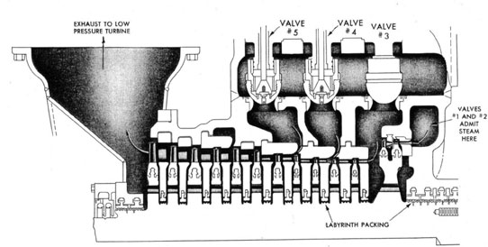
(b) Turbines.-Figure 41 is a simplified diagrammatic sketch of a section of the high-pressure turbine. The space shown on the right of the drawing (labelled valves Nos. 1 and 2) is the steam chest of this turbine. The steam enters here through the two nozzle control valves, passes through the first-stage nozzle, and increases in velocity due to the drop in pressure across the nozzle. While travelling at high velocity it impinges upon the first row of blades and due solely to the velocity of the steam, it drives these blades around carrying with them the high-pressure rotor. When the steam leaves this row of blades there is still sufficient velocity remaining to
warrant its use in a second row without restoring the velocity by another pressure drop. In order to accomplish this a row of stationary blades, attached to the turbine casing, is located as shown between the first and second rows of moving blades. These stationary blades reverse the direction of flow of steam so that it strikes the second row at approximately the same angle as the first row. In the second row of moving blades most of the remaining velocity is removed. From here the steam is led to a second-stage nozzle carried in a diaphragm attached to the turbine casing. The steam is expanded through this nozzle, and increases again its velocity, which is removed in a single row of moving blades on the discharge side of the nozzle. After each succeeding row of blades steam is passed through another nozzle to restore its velocity. pressure being dropped in each stage until the steam finally exhausts from the last stage of the turbine at a much lower pressure than when it entered. In the case of the high-pressure turbine, the steam passes through 12 stages in all
79
HIGH PRESSURE TURBINE SHOWING VALVE ARRANGEMENT
FIG. 41
80
before exhausting to the low-pressure turbine. In the case of the cruising turbine, steam passes through 8 stages before exhausting to the high pressure.
(c) Nozzle Control Valves.-Three nozzle control valves admit steam to the cruising turbine via the cruising turbine chest. Operating gear leading from the main gags board rotates a cam shaft causing cams to lift these three valves successively as it is necessary to increase speed. There are five valves which admit steam to the high-pressure turbine. These valves are cam operated in the same manner as those of the cruising turbine. The first two of these valves to open admit steam to the first-stage chest (valves Nos. 1 and 2, fig. 41) of the turbine. With valves Nos. 1 and 2 fully open, the steam pressure in the first-stage chest is approximately at line pressure and the first-stage nozzles are passing steam to the first stage at the limit of their capacity. To further increase the power and speed of the turbine it is necessary to increase the amount of steam flowing through the turbine. To do this valve No. 3 is opened. This admits steam from the main line directly into the first-stage casing from where it can flow through the second-stage nozzles. This results in an increased velocity of the steam flowing through the rest of the turbine because of the increased steam volume being forced through the nozzles. The increased volume and velocity of the steam impinging upon the blading increase the turbine power and speed. With valve No. 3 wide open it is necessary to open valve No. 4 to obtain a further increase in power. This admits steam from the main line to the third-stage casing and the fourth-stage nozzles. With this valve wide open the plant should operate at its maximum allowable r.p.m. (DD445 class, 397 r.p.m.; DD692 class, 350 r.p.m.). Valve No. 5 will, when opened, admit steam to the fifth-stage casing and the sixth-stage nozzles. This will permit operation of the turbine at its maximum speed and power (120 percent boiler load). Valves Nos. 3, 4, and 5 may be called "bypass" valves, but it is, perhaps, better not to think of them as such, since the term would seem to imply that the stages before each were not. in use. Such is not the case since all five valves open successively from No. 1 on and stay open. When closed, they close successively from the highest number in use.
(d) Low-Pressure Turbine.-Steam exhausting from the high-pressure turbine goes to the
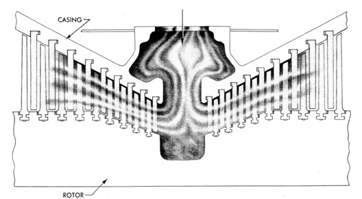
low-pressure turbine where it is further utilized. Figure 42 is a diagrammatic representation of the reaction type low-pressure turbine. This is a double-flow turbine in which steam enters at the center of the turbine and flows in both directions through similar rows of blading, except that the blades are to the opposite hand. In the case of this reaction turbine the steam, after passing through each row of blading, is reversed by a stationary row of blades so that it enters the next row of moving blades in the same direction as before. In this turbine rotation of the blades (and rotor) is accomplished by the reaction of the blade to the flow of steam away from the blade, the drop in pressure between the stages being accomplished by the shape of the blade and by shrouding attached to the blade tips to confine the steam. There are nine rows of moving blades in each half of this reaction type of low-pressure turbine. The impulse type low-pressure turbine is also a double-flow turbine, with steam entering the center and flowing in both directions. The stages are constructed in a manner similar to those of the high pressure, in that a nozzle is provided before each row of blading and the steam is expanded through this nozzle, striking upon the blades at high velocity. There are six stages in each half of this type of low-pressure turbine. At each end of the low-pressure turbine rotor is installed an astern element. This astern element consists of a single-stage impulse turbine, velocity compounded with two rows of moving blades and one row of stationary reversing blades. At the outlet of the astern element a baffle is provided to prevent the exhaust steam from blowing directly into the low-pressure element last stage. Both the low-pressure and astern elements exhaust directly into the main condenser. See section VI, paragraph 4 (Notes on Operation) relative to super-heat control when astern bells are received.
(e) Cross-Over Valve.-For normal operation of the cruising turbine. the cruising turbine exhaust leads to the high-pressure turbine chest, through the high pressure turbine, and finally into the low-pressure turbine. If the cruising turbine is operating at full load, this arrangement will allow for operation of the ship at speeds up to about 20 knots. To go above this speed, steam must be admitted directly to the high-pressure turbine. For small increases in speed above this point (to 22 knots) it is permissible to admit steam to the high-pressure chest by cracking the
81
LOW PRESSURE TURBINE
DOUBLE FLOW REACTION
FIG. 42
82
CROSS-OVER VALVE
FIG. 43
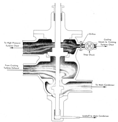
high-pressure throttle without securing the cruising throttle. Since the cruising turbine exhaust is connected directly to the high-pressure chest this will cause a back pressure to build up against the cruising exhaust. This cruising exhaust pressure should never be permitted to exceed 100 p.s.i. To increase speed above 22 knots by the above means, would develop a cruising exhaust pressure of greater than 100 p.s.i. so the cruising throttle must be closed and operation continued on the high-pressure turbine alone. Some means must be provided, therefore, to disconnect the cruising turbine exhaust from the high-pressure chest when operating under high-pressure
combination. Also, since the cruising turbine is connected to the high-pressure turbine through the cruising reduction gear, the cruising turbine will turn over with the high-pressure turbine even though no steam is being admitted to the cruising turbine. At the high speed of rotation which will exist in the cruising turbine under these conditions considerable heat will be built up. Some means must be provided to control this heat. To accomplish both of these purposes the crossover valve is inserted in the cruising turbine exhaust
line. Figure 43 shows this to be a double valve
with a common inlet to both discs. This common
inlet is from the cruising turbine exhaust. The
83
upper valve is a 6-inch valve which, when open, allows steam to pass from the cruising turbine exhaust to the first-stage chest of the high-pressure turbine. When in this position the valve is on the cruising combination. As can be seen from figure 43, closing this 6-inch valve will cause the lower (3 1/2-inch) valve to open. The opening of this valve connects the cruising turbine exhaust directly to the main condenser, and by simultaneously closing the 6-inch valve disconnects the exhaust from the high-pressure chest. A vacuum from the main condenser then exists in the cruising turbine casing. This vacuum will accomplish a certain degree of cooling of the cruising turbine. However, this will not be sufficient to keep the
cruising turbine from overheating. To carry the
built-up heat away from the cruising turbine a connection is provided from above the 6-inch valve disc leading into the cruising turbine chest. With pressure on the high-pressure chest there will be also pressure above the 6-inch valve disc. Steam is led through this connection to the cruising turbine chest, and passes through the cruising turbine, thereby cooling it. An orifice plate is installed in this cooling steam line to limit the amount of steam bled off. To prevent the passage of steam from the cruising chest through this line when on the cruising combination, a stop-check valve is installed in the line. This stop-check valve is provided with a locking device, and should be locked on "check" at all times except when the cruising turbine is disconnected from the high-pressure turbine. From the case of the valve stem is fitted a lead-off pipe to carry away any leakage past the guide stem and return it to the main condenser.
(f) Shifting Combinations.-When on the
cruising combination if an increase in speed above the maximum cruising speed is required, it be-comes necessary to shift from the cruising to the high pressure combination. If this is not properly done, it can easily cause damage to the cruising turbine by overheating. There are two methods which can be used to accomplish this shift. The first method described should be followed when there is only one man available at the throttle to accomplish the shift. In this case, the speed of the ship should be increased about two knots by opening the high-pressure throttle and increasing the high-pressure chest pressure. Then, by simultaneously closing the cruising throttle and opening the high-pressure throttle slowly,
the cruising exhaust pressure should be brought up to a point not exceeding 100 p.s.i. while still maintaining the same speed. At this point it is necessary to shift the cross-over valve and simultaneously close off completely the cruising turbine throttle. This will cause a reduction in speed equal to about the two knots picked up at the beginning of the operation and leave the ship operating with steam going to the high-pressure turbine only. The second method hereafter described is to be used when there are two men at the throttle to make the shift. In this case one man would be stationed at the high-pressure throttle and the other at the cruising throttle and cross-over valve. The man on the cruising throttle should simultaneously close the cruising throttle and shift the cross-over valve. When this is done the man on the high-pressure throttle should immediately open his valve and bring the ship's speed back up to normal. When two men accomplish this shift there will he a loss of speed of only about 10 r.p.m. It should be noted that under no conditions should the cruising turbine exhaust pressure be allowed to rise over 100 p.s.i. Should this occur it will overheat the cruising turbine with consequent damage.
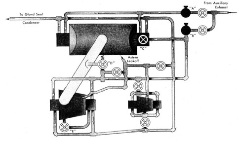
4. GLAND SEALING STEAM SYSTEM
(a) General Discussion-.In order to seal the glands of the turbines and prevent air from drawing through them into the main condenser, steam is passed into the glands to prevent the passage of air. The low pressure turbine, which operates at all times under a vacuum in its casing, must have steam admitted at all times to the glands from some external source. This steam is led from the auxiliary exhaust line, passes through a cutout valve as indicated in figure 44, then through a weight-loaded pressure regulating valve and finally to the turbine glands. This weight-loaded pressure regulating valve operates at all times to maintain a pressure of 3/4 to 1 1/2 p.s.i. to the turbine glands. In the case of the high-pressure and cruising turbines at higher speeds, the pressure on the turbine end of the forward glands will be so great that steam will bleed out through these glands, automatically sealing them. Since these glands may at times seal themselves, it is necessary to have a separate system for the cruising and high pressure turbines. For warming-up and low-speed operation, steam is led from the auxiliary exhaust line through a cutout valve and another weight-loaded valve to the glands of
84
GLAND STEAM PIPING 445 CLASS
FIG. 44
the cruising and high pressure turbines. Before the inlet to the cruising turbine glands is a valve (fig. 44) which allows steam to be cut out from these glands under certain conditions. This valve is provided with a ferrule over the valve stem to prevent its closure unless it is specifically desired to do so. In warming-up and securing conditions and at low speeds, the weight-loaded valve acts to deliver from 3/4 to 1 1/2 p.s.i. of steam pressure to the glands on both turbines. As speed increases steam will start to bleed from the turbine back into the gland steam line through the forward or high pressure glands. Since part of this steam bleeds into the gland steam supply line it now provides a source of steam for sealing the after or low pressure glands. The weight loaded valve is so constructed that when the pressure in the gland steam line reaches 1 1/2 p.s.i. it will close and admit no more steam from the auxiliary exhaust line. When this condition is reached, then the forward glands are bleeding back enough steam to seal the after glands. As speed is further increased, and we go off the cruising combination, the forward gland of the high pressure turbine is
bleeding back enough steam so that the pressure in the gland steam line will rise to excessive heights. A means is provided to unload this excessive steam and maintain a pressure in the line at a reasonable level. Valve D, (fig. 44) is an automatically operated spring loaded unloading valve. When the pressure in the gland seal line exceeds 2 p.s.i., this valve lifts and dumps the excess steam into the exhaust pipe from the high pressure turbine, from whence it can be used in the low pressure turbine. As the speed further increases a condition will exist where the high pressure turbine is exhausting at above atmospheric pressure. When the difference in pressure between the inlet and outlet of this unloading valve is less than 2 p.s.i. it will not lift and, therefore, with the pressure at atmospheric or above in the high pressure exhaust pipe, the unloading valve will not operate and the steam pressure in the gland steam line will again start to rise. In order to maintain the pressure still at normal level the needle valve C is provided which can be operated to bleed steam from the line directly into the low pressure exhaust. Opening valve C, by means of an extension rod to the main
85
gage board will allow for manual control of the gland steam pressure. At nearly full power the capacity of the needle valve is insufficient to carry away all the excess steam bled back from the forward gland of the high pressure. In order to reduce the amount of steam bled from this gland a line is provided leading from the inner end of the high pressure gland and discharging into the exhaust of the high pressure turbine. Valve E in this line must be open when the needle valve, fully open. can no longer control the pressure. For purposes of economy valve E can be opened at a much lower speed. If this valve is opened at about 25 knots it will reduce the steam bled back into the gland steam system while still allowing control of the pressure either by the needle valve or, if too much steam is bled off, by the weight-loaded supply valve. There is one other source of steam supply to this system and that is from the valve stem leakoffs of the turbine nuzzle control valves and the astern throttle valve. These valves have unpacked stems, and will allow a certain amount of steam leakage. This leakage, bled through a pipe line, can be discharged into the gland steam system or into the gland exhaust system. The gland exhaust system consists merely of a single header which collects the drains from all the glands and leads them to the gland seal condenser which is in the main air ejector shell. A cutout valve is provided at the exhaust from the cruising turbine glands. The gland exhauster takes suction from the gland seal condenser, and allows a slight vacuum to be placed on each of the glands thus drawing out the steam from the glands, and preventing it from exhausting into the engineroom. A large drain pipe is led from the gland exhaust header directly down into the low pressure drain tank. The valve in this line should always be open when operating the gland steam system. If this is not done water will build up in the gland exhaust header and. since there is insufficient vacuum in the gland condenser to drag this water out, it will remain there and prevent the passage of steam through the gland exhaust system. This will cause steam to blow into the engineroom from the glands. When the gland steam system is secured this valve should always be closed to prevent vapor from the low pressure drain tank from passing up into the gland condenser when it is not in operation. A summary of the operation of the steam system shows the following: warming-up,
stopped, backing down, and at speeds up to about 12 knots the weight-loaded valves will, when properly adjusted, automatically deliver proper steam pressure to the glands. At speeds from 12, to 28 knots. pressure should bleed back from the high pressure glands and supply steam to the system causing the weight-loaded valve to close automatically. Somewhere in this range the spring-loaded unloading valve will open dumping excess steam into the low pressure turbine and maintaining the pressure. At speeds from 28 to 34 knots the first manual operation is required. Through this range, it is necessary to control the steam pressure by manually operating the needle valve. From 34 knots to full power it is necessary to open the bypass valve from the high-pressure forward gland and to readjust. setting of the needle valve to maintain the pressure at its proper level. As noted earlier, it is not necessary to wait until this speed is reached to open this valve as it may be opened at as low a speed as 25 knots to gain economy.
(b) DD692 Class.-Arrangement of the gland steam system for the DD692 class is very similar to that shown in figure 44, which is for the DD445 class. In the DD692 class system the spring-loaded unloading valve D is eliminated as well as the bleeder valve E. The needle valve C has been changed to make it a 3 1/2-inch stop valve. This allows for sufficient. capacity of valve C to pass any amount of steam which may bleed back into the system. Therefore, when sufficient steam bleeds back to close the weight-loaded valve, valve C must, be manually operated thereafter to control the gland steam pressure through all ranges of speeds. In all other respects the system on the DD692 class is the same as shown in figure 44.
5. REDUCTION GEARS
(a) Cruising Reduction Gear.-The cruising turbine is connected to the high-pressure turbine through a single reduction gear. The cruising turbine rotor carries with it a pinion which drives the cruising gear, the cruising gear being coupled to the high-pressure shaft. The speed reduction between the cruising turbine and the high-pressure turbine is 1.779:1. The cruising turbine rotor and pinion are supported by only three bearings, one forward of the turbine and one on each side of the pinion in the reduction gear case.
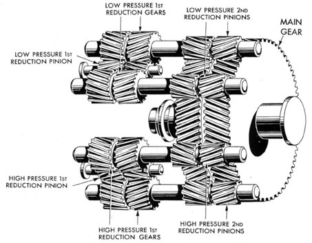
(b) Main Reduction Gear.-The high-pressure and low-pressure turbines are connected to the main shaft through a locked-train type double
86
MAIN REDUCTION GEAR
FIG. 45
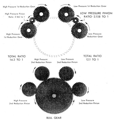
reduction gear. The arrangement of this gear is as shown in figures 45 and 46. First reduction pinions are connected by flexible couplings to their turbines and each of these pinions drives the first reduction gears. The speed ratio between the high-pressure turbine and the first reduction gears of the DD445 class is 2.562:1 and between the low-pressure turbine and its first reduction gears 2.158:1. This difference in ratio allows the turbines to operate at different speeds while driving the first reduction drive gears all at the same speed. Attached to each of these drive gears (fig. 45) is a second reduction pinion. These pinions, four in all, drive on the main bull gear which is attached to the main line shaft. The total reduction of speed, from the high-pressure turbine to the shaft is 14.3:1, and from the low-pressure turbine to the shaft is 12.1:1. Note that all four second reduction pinions operate at the same speed.
(c) DD692 Class.-The reduction gears of the DD692 class are arranged exactly the same as those for the DD445 class with the single exception that they operate with a different ratio. The maximum r.p.m. of the shaft with these gears is 350 instead of the 397 of the DD445 class while the turbines operate at the same speed. This makes the ratio for the high pressure 16.26:1 and that for the low pressure 13.69:1.
(d) Jacking Gear.-Extending from the end of the high-pressure first reduction pinion, over the bull gear to the after end of the reduction gear case, is a shaft which connects into the jacking gear through a jaw clutch. Engaging this clutch connects the high-pressure pinion to an electric motor through a train of gears, and operating this motor will turn over the high-pressure pinion, causing the reduction gear, line shaft, and all turbines to turn over. The speed of the motor and the ratio
87
REDUCTION GEAR SECTIONS
FIG 46
of the jacking gear train is such that it will cause one revolution of the main shaft in about 8 1/2 minutes. Between the jacking gear motor and the worm wheel, which drives the jacking gear train, is a coupling. Around this coupling is fitted a friction brake. If the jacking gear clutch is engaged and this brake set around the coupling the main shaft will be held stationary by the jacking gear with the ship going ahead on the other engine. It has been demonstrated that the ship can go ahead at full power on one engine with this brake in operation, and the idle shaft will be prevented from turning over. In order to engage the jacking gear clutch it is necessary to first stop the engine
either by stopping the ship or by holding the engine stationary with the astern turbine. The clutch should never be engaged underway without also using the brake and continuing oil circulation to the bearings. The gear ratio between the electric motor and the main shaft is about 16000:1 and should the shaft turn over 1 R.P.M., the motor would undoubtedly burn out.
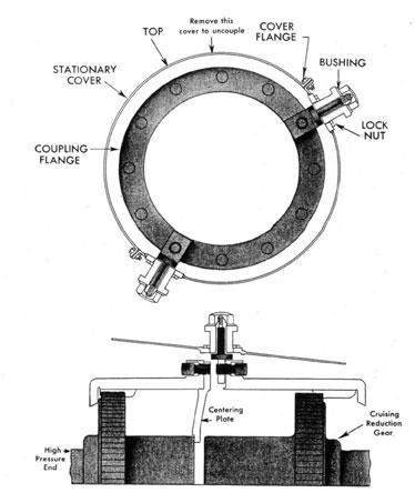
(a) Cruising Turbine Disconnecting and Locking Device.-In case of a casualty to the cruising turbine the coupling between the high-pressure turbine and the cruising turbine reduction gear may be disconnected to allow for operation of the high-pressure turbine without rotating the cruising
88
CRUISING TURBINE LOCKING DEVICE
FIG. 47
turbine. Figure 47 is an illustration of the gear necessary to be installed when this coupling is disconnected. The upper half of the cover over the coupling is first removed, exposing the coupling. Welded into the lower half of this cover are two pads with tapped boles in them. Both pads are in the same half of the cover, and are about 150 degrees apart. Also, since the cover is bolted to the high-pressure turbine casing, they are stationary. With the coupling disconnected. the high pressure half of the coupling sleeve will be loose on the high-pressure shaft, and rotation of the high-pressure turbine will cause it to flop around
and unbalance the high-pressure rotor. To prevent this, three centering plates are provided, machined to provide an exact fit as shown in figure 47. These are held to the coupling sleeve by Allen-head tap bolts through the flange and, butting against the shaft end, center the high-pressure coupling sleeve and hold it rigid. With the cruising turbine not held stationary by some means, it might be turned over occasionally, due to the windage set up by rotation of the high-pressure half of the coupling. In order to lock the turbine stationary, the pins (fig. 47) are inserted through the pads in the coupling cover previously mentioned.
89
PUMP END - LUBE OIL SERVICE PUMP
FIG. 48
The end of the pin is attached to the cruising turbine half of the coupling case by an Allen-head tap bolt and it is centered in the pad by a bushing. The whole assembly is drawn into place and the coupling case centered by adjusting the nuts on the top of the pin. An inspection of these pins (fig. 47) will illustrate the method b which they are installed. When this gear is fully installed, the upper half of the coupling cover should be replaced to prevent rotation of the high-pressure half of the coupling in the open.
6. LUBRICATING OIL SYSTEMS
(a) Main Lubricating Oil Pumps.-Each engine room is provided with two main lubricating oil pumps, the purpose of which is to deliver lubricating oil at the proper pressure to the main turbine bearings and to the reduction gear bearings and sprays. On some of the earlier installations of the DD445 class, one of these pumps is electrically driven and the other steam-driven. On later installations of the DD445 class and on all of the DD692 class two steam-driven lubricating oil pumps are provided. The DD692 class ships
90
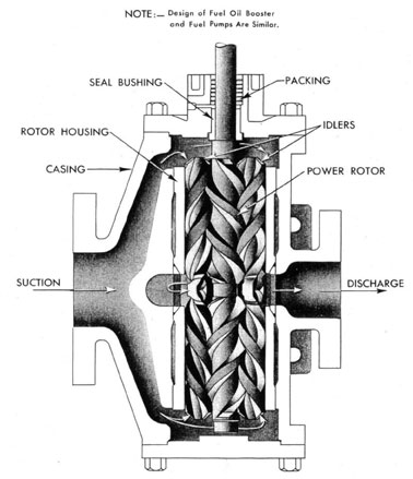
on which the piping could be changed during the building period are being equipped with an additional main lubricating oil pump in each engine room, chain driven from the main shaft. These pumps are all positive displacement rotary pumps of the general design shown on fig. 48. The center gear is the power rotor which meshes with and drives the two idler rotors. These rotors are double-ended as shown in figure 48 and the suction passage is so arranged that oil flows to both ends. There the oil is entrained by the worm-like threads of the rotors and driven toward the common discharge connection at the center of the unit. The major quantity of oil is pumped by the power rotor, the idlers serving primarily as seals although they do pump a small quantity of oil. The clearances held between the rotors and their housing are such that leakage past the threads is held to a negligible amount. In the actual installation a pin is installed at the base of each idler to provide support when the pump is not in operation. These pins have been left out of figure 48 to make the double suction of the pump more apparent. Where an electric pump is provided the electric motor and pump operate at the same speed, approximately 1,150 r.p.m. The steam pumps are driven by a horizontal turbine through a reduction gear consisting of a worm gear and worm wheel. The arrangement of this driving gear is very similar to that described in connection with the main condensate pump, section IV, paragraph 3. The gear case acts as the oil sump tank, and an attached oil pump geared from the worm wheel takes suction from this sump and discharges oil through an attached cooler to the bearings. A limit speed governor of slightly different design than that on the main condensate is also provided. The basic principle of operation of this governor is the same but the total travel of the governor valve should be adjusted for three-eighths of an inch. This governor varies the opening of the steam control valve, closing it down as the pump tends to overspeed and maintaining the pump limit speed at about 1,165 r.p.m. The normal rated speed of the pump is about 1,150 r.p.m.
The chain driven pumps noted above are arranged to furnish the primary supply of oil to the bearing and gear headers at full power, with one or both of the steam driven lubricating oil service pumps as stand-by. At low power operation the steam driven lubricating oil pump selected for
service will furnish the primary supply of oil to the headers augmented by the supply from the chain driven pump above approximately 40 shaft r.p.m. The sprockets driving the chain driven pump are designed to have these pumps, which are identical with the steam-driven pumps, deliver rated capacity when the main shaft is turning at 350 r.p.m. A one-eighth inch orifice through the seat of the steam driven service pump governor valves is provided to furnish sufficient steam to the selected stand-by service pump turbine to assure that the pump is warmed up, turning over at slow speed (about 40 r.p.m.) and will immediately pick up the load as the main shaft is slowed, stopped, or when going astern. This arrangement assures that normal bearing and spray header pressure will he maintained irrespective of the speed at which the main shaft is turning. Either one or both of the steam-driven service pumps may be lined up as stand-by during various conditions of operation. For normal service one steam-driven pump will be in operation in each engine room and the other pump secured.
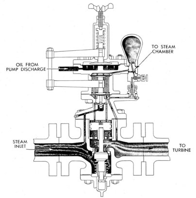
(b) Leslie Constant Pressure Pump Governor.-To control the discharge pressure of the steam pumps a Leslie constant pressure pump governor is installed in the steam line to each pump. This governor operates on the same basic principle as the Foster pump governor discussed in section V, paragraph 4. That is, a change in capacity requirement of the pump is reflected by a momentary change in discharge pressure. This change in discharge pressure causes adjustment of a pilot valve within the governor and consequent change in governor valve opening to restore the pressure to normal. In the Leslie governor (fig. 49) the pump discharge pressure is led through an actuating line to the space below a single diaphragm located in the top of the unit. The pump discharge pressure exerts an upward force on this diaphragm. To balance this force a spring is placed above the diaphragm which exerts its force on the diaphragm through the arrangement of crosshead and mushroom shown. As in the Foster governor it is the balance of these two forces which controls the operation of the governor. With the spring force greater than the upward force, the diaphragm will be displaced downward. This means the upper cross head will also move downward carrying with it the connecting rod and lower cross head. This will cause the lower cross head to press against the lower diaphragm
6705586-46-7
91
LESLIE CONSTANT PRESSURE REGULATING VALVE
FIG. 49
through the mushroom shown, thereby displacing it downward. Since the lower diaphragm is in contact with the pilot valve stem this will cause the pilot valve to be opened. The pilot valve is always supplied with steam from the inlet side of the governor valve and when it is opened steam passes through two ports to the top of the operating piston. The steam pressure exerted on the top of operating piston forces it down and opens the governor valve, admitting steam to increase the pump speed. This increase in speed is reflected by an increased discharge pressure from the pump. When the pressure has increased sufficiently so that the upward force on the upper
diaphragm is greater than the spring force the diaphragm is displaced upward. This causes a reduction in the pilot valve opening and allows a spring to close the governor valve against the now reduced pressure on the operating piston. As in the Foster governor, the oscillations are so rapid as to be reflected in a constant discharge pressure if all elements of the unit are properly adjusted. Means is provided to vary the tension on the adjusting spring. Increasing the tension will require a higher discharge pressure to restore the balance on the diaphragm and lowering the tension will produce a lower discharge pressure. The means employed in this governor to reduce
92
the "hunt'' differs from that employed in the Foster governor. An intermediate diaphragm is inserted, bearing against the top of the lower yoke through another mushroom. Steam is led from the governor valve outlet to the bottom of the lower diaphragm and from there through a needle valve to the top of the intermediate diaphragm. Thus it can be seen that any movement of the lower yoke, either tip or down, will be opposed by the force of the steam pressure on the intermediate or the lower diaphragm. This will reduce the amplitude of the oscillations of the pilot valve and consequently reduce the "hunt" of the governor. The needle valve regulates the amount of steam going to the intermediate diaphragm. If it is not properly adjusted the governor will have excessive "hunt" and "regulation." Experience has shown that, in general, opening the needle valve from one-half to three-fourths of a turn will provide satisfactory operation. However. adjustment should be made by experiment to suit the particular governor. The steam chamber (fig. 49) continuously provides proper pressure to the intermediate diaphragm although the space above it may be filled with water from condensation. Below the governor valve a valve stem is fitted which, when operated, draws the governor valve wide open permitting a full flow of steam to the turbine. This will require that the turbine speed be controlled by hand throttle. There are two positions for this valve stem, "auto" and 'manual." Under normal operation the stem should be set on "auto" to allow control of the pump by the governor.
(c) Steam and Electric Pump Interlock.-The early DD445 class installations were provided with an electric lubricating oil pump and a steam lubricating oil pump per engine. They were designed to operate with the pump discharge pressure 35 p.s.i. Before reaching the bearings, this pressure was reduced by means of an orifice plate and a weight-loaded relief valve to the normal bearing pressure of 10 p.s.i. The 35 p.s.i. pump discharge pressure was necessitated by the presence of the main turbine overspeed governor valve. This governor valve has since been removed from or made inoperative in all installations, but since the electric pump and the Leslie governor were designed for 35 p.s.i. it was necessary to retain 35 p.s.i. pump discharge pressure. In these installations the electric pump is equipped with an automatic cut-in and cut-out switch, this switch
being actuated by an actuating line which leads directly from the steam pump discharge casing. This switch is so adjusted that. when the pressure discharged from the steam pump drops to 25 p.s.i., the cut-in switch makes contact and automatically starts the electric pump. With the electric pump in operation, if the steam pump discharge pressure is brought up, the contact breaks and the electric pump is automatically shut down. This cut-out pressure should be set as high as possible to prevent the danger of the pump shutting down due to its own pressure. This automatic feature of the electric pump will only be in operation when the switch on the electric pump controller is set in the automatic position. Note that the electric pump cuts in and cuts out only on a change in pressure of the steam pump. The actuating line to the Leslie constant pressure pump governor leads from the lubricating oil line before the orifice plate, the orifice plate being located at the strainer inlet. In this manner we have pressure in the actuating line to the Leslie governor no matter which pump is in operation. If the governor is then set for 30 p.s.i. and the electric pump is operating at 35 p.s.i., this actuating pressure in the Leslie governor will hold the governor valve closed. However, should the electric pump pressure drop below 30 p.s.i., for whatever reason, the Leslie governor will open and admit sufficient steam to the steam pump to run it at a speed which will maintain the 30 p.s.i. pressure in the actuating line. If the electric pump is operating normally we could then leave the steam pump lined up and it would act as a standby to take up the load in case of a casualty to the electric pump. However normal underway operation is with the steam pump in use, and the electric pump standing by with its controller set on automatic. With this set-up if the steam pump discharge pressure should fall to 25 p.s.i. the electric pump will automatically start up and restore the pressure to normal. In doing this, the actuating pressure to the pressure regulating valve, will return to normal and remain there, causing the regulating valve to shut off steam to the steam pump and stop it. To make this set-up work most efficiently both ways the Leslie governor should normally be adjusted for a discharge pressure of 30 p.s.i. and the recirculating valve, from the electric pump discharge back to the lubricating oil sump tank, should be open to maintain the electric pump discharge at 35 p.s.i.
93
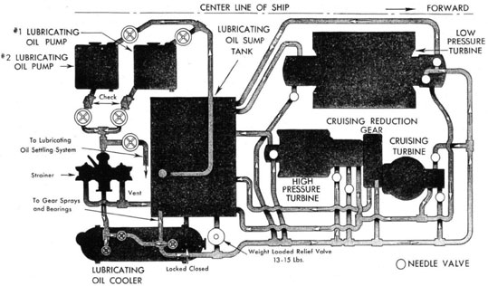
DD445 CLASS
MAIN LUBRICATING OIL PIPING
#1 ENGINE ROOM
FIG. 50
94
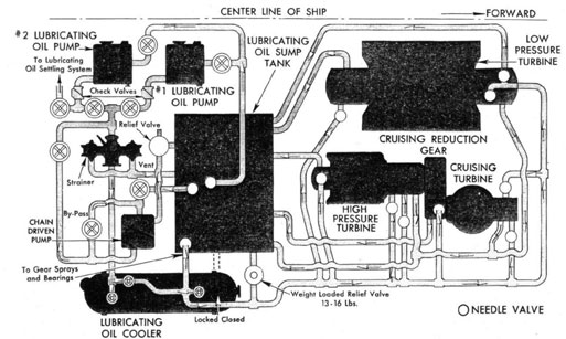
DD 692 CLASS
MAIN LUBRICATING OIL PIPING
#1 ENGINE ROOM
FIG. 50A
25
(d) Steam Pumps-Interlocks.- Where two steam-driven lubricating oil pumps are installed the Leslie pump-governor, designed to operate at a lower pressure, has also been installed. This allows for the removal of the orifice plate. The actuating line for the Leslie valves in this installation comes, not from before the strainer, but from the lubricating oil line beyond the lubricating oil cooler. This allows the Leslie governor to operate the pump at a speed which will maintain the proper pressure at the bearings, and no other control of pressure is needed in the lubricating oil line. It is possible with these two governors to set up the pumps so that one will stand by for the other. If one governor is adjusted for a discharge pressure of 10 p.s.i. and the other for a discharge pressure of 8 p.s.i., the 10 p.s.i. pump will operate and the 10 p.s.i. of actuating pressure working on the Leslie valve set at 8 p.s.i. will hold that valve closed and allow no steam to enter its turbine. If, due to a casualty to the 10 p.s.i. pump the actuating pressure drops to 8 p.s.i., the 8 p.s.i. pump will be started by the Leslie valve to act as a booster or to take over the full load at 8 p.s.i. should the 10 p.s.i. pump stop entirely. Either pump can be adjusted for 10 p.s.i., with the other at 8 p.s.i.
(e) Lubricating Oil Supply System.-T his system supplies oil under pressure to the reduction gears and to all main turbine bearings for the lubrication of these gears and bearings. Figure 50 shows the arrangement of this system. This arrangement is for all installations in the DD445 and DD692 classes in which two steam lubricating oil pumps are installed. Where one electric and one steam pump are installed the only difference is that a 3 1/4-inch orifice plate is located just before the strainer and the weight-loaded relief valve lending from the main bearing header is adjusted to start lifting at 10 p.s.i. The two lubricating oil pumps take suction from the bottom of the main reduction gear case which acts as a lubricating oil sump tank. Oil from here is discharged, through a check valve after each pump, through a discharge cut-out valve and finally into a common discharge line which leads through the strainer. The strainer is a double-barrelled strainer which is capable of having the flow shifted from one barrel to the other for cleaning purposes. From the strainer the line leads to the top of the lubricating oil cooler, through a valve there and into the cooler. Leaving the cooler at the opposite
end the oil flows aft for a foot or so and then divides. One line leads to the main reduction gear oil header to supply oil for the reduction gear internal system. The other line leads forward past the weight-loaded relief valve and provides the main bearing header for the turbines. From this main bearing header are led all the oil supply lines to the main turbine bearings and thrust bearings. Before entering each bearing, the oil passes through a needle valve, adjustment of which will regulate the amount of oil delivered to each bearing. These needle valves are so constructed that they cannot cut off fully the flow of oil to the bearing. Their normal adjustment is in a position which is about half way between their fully open and fully closed position. With this adjustment the turbines should operate at full power with a rise in temperature of oil through the bearings of approximately 20 degrees F. In case a bearing is wiped the enlarged oil clearance might rob other bearings in the system. The needle valve opening can be reduced to prevent this. Should a needle valve become fully closed it will still allow sufficient flow of oil to the bearing to allow for operation at full power with a rise in temperature of 50 degrees F. to that hearing. The drain system from the bearings consists of a separate drain from each of the after bearings of the low pressure and high pressure turbines. The drains from the forward and thrust bearings of all three turbines are collected by a single header. All these drains lead directly into the lubricating oil sump tank. The cruising turbine reduction gear which is also supplied with oil from the main bearing header, drains to the sump tank through a separate drain line. A branch line lends from before the lubricating oil strainer and joins with the lubricating oil purifying and settling system to allow for bleeding oil from the supply system for purification. A bypass is provided around the cooler. From the base of the cooler is led a drain line which discharges into the sump tank. The valve on the base of the cooler is fitted with a lock, and should be at all times locked "closed." The major purpose for using this drain line is when it is necessary to heat the oil. By putting exhaust steam in the cooler before pumping oil to the bearing, oil can be circulated through the cooler back to the sump tank and heated.
(f) Special Notes.-To provide proper lubrication of the bearings even though the engines are merely jacking over it is essential that the oil
96
temperature be at least 90 degrees F. when pumping to the bearings. Oil should always be pumped to the bearings when the turbines and gears are being jacked over or when the, jacking gear is being used under way to prevent the shaft from turning over. Except as noted above, it is not desirable to pump oil to the bearings unless the engines are being jacked over. When securing, under no circumstances should jacking of the engines be stopped until the oil temperature has dropped to at least 100 degrees F. When securing, cooling water to the oil cooler should be secured as soon as possible to prevent too rapid cooling of the oil. Should the main reduction gear be allowed to cool too rapidly, a great deal of condensation will form in the reduction gear case. This will cause rusting of the gears as well as cause water to be collected with the oil in the sump tank. In order to reduce this amount of condensation to a minimum it is necessary to continue jacking the engines for at least two hours after securing the vacuum in the main condenser, allowing the oil temperature to cool down very slowly and never allowing it to drop below 90 degrees at any time. This operation will allow reduction gears to cool down slowly enough to prevent the condensation which would occur if cooled rapidly.
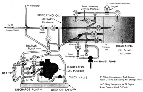
(g) Lubricating Oil Purifying and Settling System.-In addition to the lubricating oil supply system, a purifying and settling system is installed which will allow for the transfer of oil from one plant to the other and also allow for purifying of the lubricating oil in both engine rooms. A lubricating oil purifier is provided in each engine room in order to separate impurities and water from the oil. In the forward engine room the lubricating oil settling tank is installed on the upper level but there is none in the after engine room. Figure 51 shows the lubricating oil settling and purifying system in the forward engine room as installed in all DD445 and DD692 class ships. By referring to this drawing it can be seen that the purifier can take suction from either the sump tank, the storage tank, or the generator sump tank. Also a suction is provided to the bull-gear oil pan on DD445 class ships. All of these suction leads join together in a common line which leads to the suction pump of the purifier. This line also leads past the purifier into the lubricating oil settling tank, which allows the purifier to take suction from the settling tank itself. The branch from the lubricating oil service system, previously
mentioned, joins into this same suction line. The purifier suction pump discharges through a lubricating oil heater the purpose of which is to heat the oil to a proper temperature (160 degrees F.) before it enters the purifier bowl. A bypass line leads from the purifier suction pump discharge directly into the bowl for use when desired. Another bypass leads from the suction line directly into the bowl, bypassing the suction pump. When purified, the oil passes from the bowl to the purifier discharge pump and is pumped into a discharge line. This discharge line leads to the lower level with branches into the storage tank, the sump tank, and back to the generator. A branch also goes to the settling tank. In addition to these places the discharge line from the purifier leads to a cross-connection line which passes through the bulkhead and joins this system in the other engine room. At the bulkhead is a locked valve to cut out this cross-connection, which should be locked at any time the line is not in use. The same cross-connection line leads also into the purifier suction line so that we can either discharge through this line into the other system or take suction from the other system through this line. In order to allow for rapid transfer of lubricating oil from the storage tank to the sump tank or to the other system, a line is provided leading directly from the purifier suction pump discharge line into the purifier discharge line. This bypasses the entire purifier with the exception of the suction pump. However, the capacity of the purifier bowl is so nearly equal to the capacity of the suction pump that no advantage will be gained by not putting the oil through the purifier bowl when transferring. The after system is, of course, on the opposite side of the ship but, with the exception of the lubricating oil settling tank and its connection, it is arranged in exactly the same manner as the forward system. Filling lines for the lubricating oil systems are provided in each engine room to the storage tank only. In addition, in the forward engine room a filling line is provided leading to the lubricating oil settling tank. It is not possible to fill directly into the sump tank. To do so it would be necessary either to pump the oil from a storage tank into the sump tank or allow the storage tank to overflow into the sump tank when filling. Since the storage tanks vent into the sump tanks it is possible to fill them to 100 percent of capacity as expansion of the oil would cause it to overflow only into the sump tank and would not put a
97
LUBRICATING OIL SETTLING AND PURIFYING
#1 ENGINE ROOM
FIG 51
98
pressure on the storage tank. Navy symbol 2190T lubricating oil should be used in the main and generator lubricating oil systems.
(h) Procedure in Case of Loss of (or Low) Lubricating Oil Pressure.-Buships Ltr. S41-1 (641-640-800) over S42 over EN28/A2-11 of 25 October 1944. is quoted herewith in part:
2. Extensive derangements of main propulsion machinery have resulted from the loss of lubricating oil pressure. In many instances the loss of lubricating oil pressure has been due to improper operational procedure rather than material failure; and the resulting damage has been unnecessarily extended by the following unsound procedures:
(a) Partial checking of shaft speed, instead of stopping shaft rotation.
(b) External examination of bearings including check of sight flows and temperatures, which usually appear to be normal, rather than thorough examination.
(c) Resumption of operation, with aggravation of the damage.
3. It must be Impressed on all personnel concerned that:
(a) Even momentary loss of flow of lubricating oil will result in localized overheating and probable slight wiping of one or more bearings although only a momentary, moderate rise may occur in the temperature of lubricating oil discharge from the bearing(s).
(b) Stopping shaft rotation and restoring lubricating oil flow as rapidly as possible will prevent or minimize damage.
(c) Operation on wiped bearings will cause serious derangement to the shaft packings, oil seals, and blading.
4. Operating personnel must thoroughly understand the precautions and the procedures to prevent low lubricating oil pressure, and also be trained in a sound procedure should this serious condition occur.
5. Loss of lubricating oil pressure may be caused by:
(a) Failure of the system itself, including the main lubricating oil pumps.
(b) Failure of power supply steam or electric, to the main lubricating oil pumps due to an operational casualty or damage to boilers, steam lines, or electrical equipment.
6. Failures of the system may be caused by presence of dirt, rags, or other foreign material due to improper cleaning; to a piping failure: or failure of the operating pump, coupled with failure of the stand-by pump to start (or to be started). Stand-by pumps shall be maintained ready to start the moment the pressure drops below the prescribed operating range. Where automatic starting devices are not provided on steam-driven pumps, the pumps shall be lined up so that opening the throttle is the only action required to start the pumps. Steam supply lines to standby pumps shall be drained continuously. Where electrical pumps are installed personnel must be thoroughly familiar with alternate sources of power.
7. Loss of steam pressure due to battle damage may be unavoidable. Split-plant operation is prescribed when maximum damage control is required to prevent total loss of power; therefore cross-connection valves between split-plants must not be opened until damage is isolated. Complete loss of steam pressure due to operational casualties such as low water in boilers or water in fuel oil usually
can be prevented by prompt action of the throttle-men in closing their throttles when steam pressure drops below a selected pressure and by slowing down auxiliary machinery, thus conserving the available steam for the lubricating oil pumps and vital auxiliary machinery and providing time to open cross-connection valves when it is safe to do so.
8. The lubricating oil low pressure alarm should be adjusted to sound at the lowest safe operating pressure for full power operation, as stated in the Main Propulsion Machinery Instruction Book.
9. General procedure for low lubricating oil pressure condition.
(a) On sounding of the low pressure alarm or other indications of loss of oil pressure, immediately stop the affected shaft and simultaneously endeavor to regain lubricating oil pressure.
(1) If the steam pressure is available close the throttles in use and stop shaft by use of astern throttle, or vice versa. Engage the jacking gear and apply jacking gear brake if provided. If speed is in excess of one-half full power speed it may be necessary to slow down the vessel in order to stop the shaft and engage the jacking gear. While shaft is turning, keep continuous check on gages and sight glasses, watching for a reduced or interrupted flow. Listen for and endeavor to locate the source of any unusual or abnormal sounds. After securing the affected shaft, the ship's speed may be increased to the limit for lock-shaft operation.
(2) If steam pressure is lost in one engine room during split-plant operation and unless the tactical situation positively prevents, take way off ship by backing other engine(s). Concurrently determine the nature of the casualty or damage causing the loss of steam. If it will not cause loss of steam to the other plant, open auxiliary and main steam cross-connections immediately. If damage would cause loss of steam to other plant, isolate damage and then open auxiliary and main steam cross-connections as soon as practicable. Stop and lock the affected shaft as soon as steam is available.
(3) Concurrently, make every effort to regain lubricating oil pressure:
(a) Check lubricating oil pump in use. If not operating, start stand-by pump.
(b) Shift duplex strainers.
(c) Check sump level. If low, replenish oil.
(d) Locate and repair any leaks.
(b) Concurrently with the above steps, inspect all bearings and endeavor to determine which have been overheated. Do not rely on thermometers alone. A thermometer may have indicated only a slight, unobserved, momentary rise.
(c) Secure gland sealing steam and the main air ejectors (air pumps) to minimize main turbine rotor distortion.
(d) Inspect and clean lubricating oil strainer basket not in use. Note whether flakes of bearing metal are present in strainer.
(e) Start lubricating oil purifier if not in use.
(f) Continue circulation of lubricating oil until bearings are sufficiently cool for inspection and maintain the
670586-46-8
99
lubricating oil system in operation at all times except when inspecting bearings so that lubrication will be provided if shaft-locking gear should fail.
(g) Take bearing-wear micrometer readings of all bearings and axial clearances where means are provided.
(h) Proceed with the inspection of bearings. Raise bearing caps and roll out shells. The inspection must be as thorough as circumstances will permit, realizing the importance of subsequent reliable performance and weighing it against the time required to inspect suspected bearings.
(i) It is possible that the bearing trouble is isolated and only one or a few bearings are wiped. It is realized that a thorough examination of the main reduction gear bearings may not be practicable immediately following such a machinery derangement, but the following procedure is recommended:
(1) All turbine and cruising reduction gear bearings should be thoroughly inspected.
(2) Main reduction gear bearings that are accessible without lifting the gear casings should be thoroughly inspected. Inaccessible main reduction gear bearings should be examined through inspection openings for flow of babbitt along the shaft.
(3) Reduction gear bearing thermometers should be removed to check for oil flow from the wells. Absence of oil flow from a well indicates that the bearing may be wiped to the extent that the oil passage to the thermometer has been closed. When such a condition exists, a below normal reading would be shown by the thermometer when the shaft is operating. Also there may be a stoppage of oil to the bearing.
(4) The oil strainer basket in use should be examined for the presence of babbitt flakes.
(5) If examination of main reduction gear bearings shows no indications of wiping and only one of the turbine and cruising gear bearings is found to be wiped, the main reduction gear bearings may be assumed to be undamaged, and the shaft may be operated at the minimum speed which the tactical situation will permit until such time as a thorough examination of the main reduction gear bearings can be made by tender or yard repair forces.
(6) If several of the turbine and cruising reduction gear bearings are found to be wiped. It is probable that some of the main reduction gear bearings are
also wiped, and the shaft should not be operated until such time as proper inspections and repairs can he made.
(j) The Bureau desires to emphasize that when operation is resumed after a shaft has been locked for several hours the turbine rotors are probably bowed, and steps must be taken to correct this condition. If the tactical situation will permit. the ship should be stopped and the engine warmed up in the routine manner. If such is not permissible, and it is not desired to proceed on the remaining engine(s) to a location where the engine can be warmed up in the routine manner, the ship should be slowed to the minimum allowable speed, and the following procedure followed:
(1) Admit steam to the astern throttle to remove or ease strain from the jacking gear and to prevent the shaft from rotating at such speed as to cause vibration.
(2) Unlock the jacking gear shaft locking device (if fitted).
(3) Disconnect the jacking gear (if fitted) or shaft-securing device.
(4) Simultaneously with the above cut in the gland sealing system and one stage of the main air ejector (or approximately 20" vacuum if main air pumps are installed).
(5) Crack the ahead throttle to provide a feather of steam to equalize heating of the rotor.
(6) Ease the idle shaft by slowly closing the astern throttle, keeping the shaft speed below the sensible vibration speed. During this operation the turbine rotors are heated by the equalizing steam flow (subpar. 9 (j) (5) above) and windage, will gradually straighten themselves without damage. If the installed thermometers have sufficient range, the observed temperature of the exhaust should not be permitted to exceed 450 degrees F. During this period the main condenser must be cooled normally (scoop or main condenser circulating pump).
(7) When the idle shaft has been eased up to its free dragging speed the full vacuum should be raised and the engine should be reported ready.
(k) Before disengaging a locked shaft the temperature of the main steam should be reduced as much as practicable. In ships equipped with superheat control boilers the superheater burners in time affected plant should be cut off.