The auxiliary plant as installed in both the DD445 and DD692 class is just a miniature main plant. It consists of an auxiliary condenser, an auxiliary circulating pump, an auxiliary condensate pump, an auxiliary air ejector and an auxiliary feed booster pump. It uses the deaerating feed tank instead of having a separate auxiliary deaerating feed tank. The operation of each of these units is the same as described with the main plant, except that their capacity is far less. The ship's service turbo-generators exhaust either into the auxiliary condensers or into the main condensers. If exhausting into the main condenser, it is unnecessary to operate the auxiliary plant. When not underway, however, in order to maintain electrical power on the ship an auxiliary plant must always be in operation. Steam piping to the ship's service generators is provided from the main steam system. When getting underway it is recommended that the generator be placed in operation as soon as possible, but it should continue to be exhausted into the auxiliary condenser until the ship has squared away at sea.
2. DD445 CLASS. SHIP'S SERVICE TURBOGENERATORS
(a) General Discussion.-The Ship's Service generators installed in all DD445 class ships are driven by a six stage horizontal turbine through a reduction gear. They are rated at 290 kw.; 250 kw. of which is at 450 volts AC and 40 kw. at 120 volts DC. The turbine operates at 10,012 r.p.m. which speed is reduced through the reduction gear to 1,200 r.p.m. at the generator shaft. The turbine gear and generator are mounted on a common base, which base forms a lubricating oil sump tank for the unit. No CMM. MM1/c, MM2/c or MM3/c should be considered qualified to stand an engineroom watch until he can single-handedly warm-up, cut-in, parallel and secure a ship's service generator.
(b) Lubricating Oil System.-A self-contained lubricating oil system is provided for the purpose of supplying oil to all bearings, to the reduction gear sprays and to the governor system. An attached pump takes suction from the sump tank,
discharges through a cooler and distributes oil throughout the unit. The normal pump discharge pressure is about 50 p.s.i. The pressure is restricted to this level by means of a relief valve which discharges back into the sump. Ahead of the cooler is a control valve which normally should be adjusted to allow the oil delivered to the bearings and sprays of the unit to be maintained at approximately 8 p.s.i. Oil to the governing system comes directly from the pump discharge and is, therefore, under about 50 p.s.i. pressure. A low pressure alarm set for 4 p.s.i. is also provided.
(c) Gland Sealing Steam System.-A gland sealing steam system is provided to seal the turbine glands at both ends. A manifold of three valves, located on the side of the unit, is connected to the auxiliary exhaust line to provide steam for the glands at low loads. The center of these three valves controls the admission of auxiliary exhaust steam. The right hand valve controls the admission of steam to the low pressure gland of the turbine. Under high loads, when sufficient steam bleeds back from the high pressure gland to seal the low pressure gland, the center valve may be closed. When excessive pressure is bleeding from the high pressure gland the left-hand valve should be opened to bleed-off this excess pressure into the third stage of the turbine. Drains from these glands lead into the low pressure drain system.
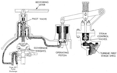
(d) Constant Speed Governing System.-A governing system is provided which operates to vary the steam admitted to the turbine, in order to maintain constant speed at varying electrical loads. Figure 64 is a diagrammatic representation of this system. The governor weights shown, are connected to the governor pilot valve. Around this pilot valve is located the pilot valve bushing, which is capable of moving up and down within its housing. The governor weights are connected through a worm and pinion to the reduction gear, and are rotated at a speed of 675 r.p.m. at the turbine rated speed. Centrifugal action of these governor weights causes them to move outward, the degree of motion depending directly upon the speed of rotation. It is apparent from figure 64 that, as these weights move outward the pilot valve itself is pulled down. When the generator
130
CONSTANT SPEED GOVERNOR
TURBO-GENERATOR
DD 445 CLASS
FIG. 64
is first placed in operation these weights are in their fully down position and the pilot valve is raised to its full height. At this time the restoring lever, which is connected to the pilot valve bushing. will be in its extreme downward position. This will cause the pilot valve bushing to be in its downward position while the pilot valve itself is in its upward position. Oil is led directly from the oil pump discharge to the upper ports of the pilot valve bushing. With the pilot valve up and the bushing down these ports are open, and oil can then flow through the ports directly to the base of the operating piston following the path shown in Figure 64. Of course with the generator at rest there is no discharge pressure from the attached oil pump. In order to lead pressure to the pilot valve when starting the generator it is necessary to operate the hand pump. Putting pressure on the base of the operating piston will force it upward in its cylinder. When this occurs the rocker arm shown connected to the operating piston, will rise and carry with it the connecting rods which actuate the steam control valves. The
six steam control valves have their sterns passing freely through a crosshead. Collars, on the top of each stem, are staggered in height so that, as the cross-head is lifted by the connecting rods it lifts successively each steam control valve. With the steam control valves open, steam is admitted directly to the turbine steam nozzles, rotating the turbine. As the turbine speed increases the governor weights move outward and, in moving outward cause the pilot valve to be drawn down. As the valve is drawn down it closes off the upper port of the pilot valve bushing thereby cutting off the oil supply to the operating piston; but, since the system between the pilot valve and operating piston is entirely closed, the pressure previously built up will remain in that system, holding the operating piston at whatever height it may have risen to. As the turbine speed rises too high the pilot valve continues to be lowered. This causes the lower ports of the bushing to be opened while still keeping the upper ports closed. This allows pressure to bleed from the operating piston, dumping the oil into the reduction gear case. As
67086-46-10
131
this pressure is reduced the operating piston moves downward thereby reducing the opening of the steam control valves. When the turbine is again at its proper speed the low port will be again closed and, with the tipper port closed, the governor system will be in a condition of stability with the proper pressure maintained on the operating piston to cause sufficient opening of the steam control valves to maintain the turbine rated speed. Should the load increase this would cause the turbine to tend to slow down. This slowing will allow the governor weights to move inward and raise the pilot valve. Raising the pilot valve will again open, partially, the upper port of the pilot valve bushing and allow more pressure to he transmitted to the operating piston, thereby admitting more steam to the turbine and restoring it to normal speed. The restoring lever is connected to the steam control unit connecting rods and as those connecting rods rise, admitting more steam, the restoring lever also rises and carries with it the pilot valve bushing. This brings the bushing up to a position where the upper port is again closed off, leaving the system again in a stable condition. As the load decreases the speed will tend to increase, causing the governor weights to move further out. This will pull down the pilot valve, opening the lower port of the pilot valve bushing and allow pressure from the operating piston to bleed off, thus reducing the opening of the steam control valve. As the steam control valves are closed the restoring lever is also moved downward. moving the pilot valve bushing down and causing the lower port to be closed off; again restoring the stability of the governing system. Thus we see that the degree of opening of the steam control valves depends upon the relative positions of the pilot valve and pilot valve bushing the pilot valve being the speed control part of he governor and the bushing having its position varied depending upon the load. Of course, under no-load conditions varying the position of the pilot valve bushing will vary the speed, but where two generators are operating in parallel varying of the location of the pilot valve bushing will not change the speed but will change the percentage of total load carried by that particular generator. At the left-hand end of the restoring lever is provided a hand wheel and threaded stem, the operation of which will cause that end of the restoring lever to move up or down, thus moving the pilot valve
bushing to vary the speed which the governor will maintain.
The governed speed of the turbine may also be electrically controlled from the switchboard by means of the synchronizing device motor which is connected through a small gear train to the lower end of the stem of this handwheel.
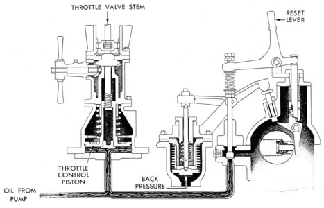
(e) Throttle Valve.-The throttle valve installed with this generator does not directly control the flow of steam to the turbine chest. The flow of steam is controlled by the steam control valves located between the throttle valve and the turbine chest, which are operated by the governor mechanism. The throttle valve only admits steam tip to the control valves. This throttle valve is so arranged that it cannot be opened unless oil pressure from the hand pump discharge or from the attached oil pinup discharge is led to its control piston. Therefore, it is apparent that in order to allow steam to pass to the steam control valves, the hand pump must first be operated, not only to actuate the governor mechanism but also to force open the throttle valve. A hand wheel is attached to this throttle valve. Unless oil pressure is being discharged to the throttle control piston. operating this hand wheel cannot cause the throttle valve to open. In figure 65 this handwheel is shown operating through a bevel gear to turn the lower portion of the throttle valve stein. This lower portion of the throttle valve stem is threaded into the throttle control piston. In the position shown in figure 65 this stem is all the way up in the piston and, when oil pressure is placed on the bottom of the piston to move the piston up, it will carry the stem with it and open the throttle valve. If the hand wheel is so operated as to run the thread down through the throttle control piston, this will cause the throttle valve disc to be moved downward and close off without moving the throttle control piston. This thread can be adjusted to give any desired degree of opening of the throttle valve. However, with no oil pressure on the throttle control piston. turning this hand wheel will merely cause the piston to be raised or lowered without moving the throttle valve disc. Thus it can be seen that unless oil pressure is placed on the throttle control piston the throttle valve itself cannot be opened to admit steam to the steam control valves.
(f) Emergency Tripping Device.-The oil-operated feature of this throttle valve is utilized in the operation of the emergency tripping device.
132
OVERSPEED AND BACK PRESSURE TRIP
445 CLASS
FIG. 65
A small weighted plug is located in the end of the turbine shaft and inside the forward bearing housing. Figure 65 illustrates the method of insertion of this plug in the shaft. A bell crank pinned in its center and capable of rotating about this pin is also located within the forward bearing housing. A vertical push rod (Fig. 65) rests on a minute ledge on this bell crank when the tripping device is in the set position. Connecting from this push rod to a valve stem is a rocker arm which, when the device is in the set position, holds the valve stem down and the valve consequently closed. Oil pressure from the same line which supplies the throttle control piston is led to the base of this valve. As the speed of rotation of the generator shaft increases to its tripping speed of 1,320 r.p.m., the plug in the shaft has sufficient centrifugal force to overcome the force of the spring working against its base flange. At this speed the plug will tend to move outward from the shaft
and, in doing so strike the lower end of the bell crank. This causes the bell crank to rotate around its axis and allow the push rod to slip off of the minute ledge upon which it rests. Dropping this push rod actuates the rocker arm and allows the valve to lift. The outlet side of this valve is connected into the open housing as shown, and, when the valve lifts, the oil pressure is released, releasing also the oil pressure on the throttle control piston and causing the throttle valve to be dosed by the action of the spring working on top of the piston. A back-pressure tripping device is also provided to cause the generator to trip out when the exhaust pressure from the generator reaches a level of from 6 to 9 p.s.i. gage. The exhaust pressure from the turbine is led into a bellows. The bellows is connected to a push rod which operates another rocker arm. The opposite end of this rocker arm rests against a button which extends through the forward bearing housing to just miss
133
making contact with the opposite end of the bell crank. When the back pressure becomes excessive it causes the bellows to be squeezed together, raising the push rod and forcing the rocker arm down against the button, thereby causing it to make contact with the bell crank arid displace it. This causes the same action as previously described in connection with the overspeed trip, dumping pressure from the throttle control piston and closing the throttle valve. Under no circumstances should the tripping device be reset without first operating the throttle valve handwheel to run down the valve stem through the operating piston so that the throttle valve cannot be opened. This will prevent the throttle valve from suddenly slamming wide open when the reset lever is operated, closing off the tripping valve. If this should happen a shot of water could very easily be allowed to enter the turbine. The trip can he reset when the generator speed has dropped 100 r.p.m. below normal. Then, operating the throttle valve handwheel will allow the valve to be opened slowly instead of suddenly. Whenever the generator is to be shut down it should be done by pressing down on the button end of the back pressure rocker arm, thus causing the generator to be manually tripped out. It is desirable whenever first starting a generator to always bring it up to its tripping speed and cause it to trip out, in order to test the operation of the overspeed trip. In any case these trips should be periodically operated in order to prevent the moving parts from becoming frozen, and consequent failure in an emergency.
3. DD692 CLASS, SHIP'S SERVICE, GENERATORS
(a) General Discussion.-The ship's service generators installed in the DD692 class ships are of a similar design to those previously discussed for the DD445 class, but are of much greater rating. The generator is rated for 400 kw. at 450 volts AC. and 50 kw. at 120 volts DC.; making the total power of the generator 450 kw. The generator is driven at 1,200 r.p.m. by a turbine connected to it through a reduction gear. The rated turbine speed is 10,059 r.p.m., the gear ratio being slightly greater than that in the DD445 class generator.
(b) Lubricating Oil System.-The lubricating oil system of this generator is exactly the same as that described for the DD445 class generator, with the sole exception that the low-pressure oil alarm is set to operate when the oil pressure drops to 5
p.s.i. instead of the 4 p.s.i. required in the DD445 class.
(c) Gland Sealing Steam System.-The gland sealing steam system is practically the same as that described for the DD445 class. The valve manifold, however, appears at the forward end of the generator turbine instead of on the side, and the bleeder valve, used to exhaust excessive pressure, discharges into the turbine exhaust instead of the third stage.
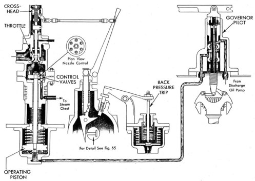
(d) Governor Mechanism.-The arrangement of the governor pilot valve and pilot valve bushing, together with its operation, is the same as that described in connection with the DD445 class governor mechanism. However, the arrangement of the steam control valves and the operating piston is considerably different. This is readily apparent in figure 66. The governor operating piston has a piston rod attached to it which carries a circular cross head at its upper end. Passing through this circular cross head are the six steam control valves which admit steam to the turbine steam nozzles. The plan view shown on figure 66 indicates that these valves are located in a circle through this cross head. The nuts shown on the control valve stems above the cross head are staggered in height so that raising the cross head will successively open the control valves. A change in the oil pressure passed to the operating piston by the governor pilot valve and bushing will cause the piston to be raised or lowered, carrying with it the cross head, which in turn causes the control valves to open or close successively. Steam is led from the control valves to the turbine chest through three separate external pipes. In all other respects the operation of the governor mechanism is the same as that previously discussed. Since the restoring lever, connected to the pilot valve bushing, cannot be directly connected up to an external lever, as in the DD445 class, it is connected to the operating piston rod through a series of connecting levers. which effectively transmit the motion of the operating piston back to the pilot valve bushing, causing the same action as described for the DD445 class governor.
(c) Throttle Valve.-The throttle valve for this class differs considerably from that installed on the DD445 class generators. This is not an oil-operated throttle valve. Figure 66 shows this valve located just above the control valve cross head, and in the same housing. The stem of this throttle valve passes through a cross head.
134
GENERATOR GOVERNOR AND TRIPS
692 CLASS
FIG. 66
135
as indicated in figure 66, and then leads on up to a handwheel. A strong spring works down at all times against the cross head. In order to cause this throttle valve to open by turning the handwheel, the cross head must be held stationary and prevented from moving along the thread, otherwise turning the handwheel would merely run the cross head up or clown on the thread and not affect the throttle valve. In order to hold this cross head stationary a toggle shown setting in a notch in the lower right-hand corner of the crosshead, is provided. This holds the cross head up against the spring pressure, and when the throttle handwheel is turned the cross head. being unable to move, remains stationary; and the valve stem rises or chops through it, thereby causing the throttle valve to open or close. The toggle has a lever attached to it which is in turn connected to the emergency tripping device of the generator. The only time that this toggle can be engaged in the notch of the cross head is when the throttle valve handwheel is in the fully closed position. To engage the toggle, the emergency tripping device must be set. This means that the emergency tripping device cannot be placed in the set position unless the throttle valve is closed, and it also means that the throttle valve cannot be opened unless the emergency tripping device is placed in the set position to hold the cross head stationary.
(f) Emergency Tripping Device.-Except for its method of closing the throttle valve the emergency tripping device attached to this generator is the same as that discussed in connection with the DD445 class generator. The same plug is inserted in the generator shaft, which, when the
turbine overspeeds, strikes the bell crank, causing the push rod to drop from the ledge on which it rests. From here on the action differs slightly, in that dropping this push rod causes the handle (fig. 66) to move forward suddenly. This handle is connected, by a connecting rod, to a lever, which is attached to the throttle valve toggle. When the handle moves forward suddenly it carries with it the connecting rod, causing the lever to be turned and consequently turning the toggle out of the notch in the cross head. This frees the cross head and allows the spring pressure, above the cross head, to push it down, carrying down the throttle valve stem and closing off the throttle valve. In this position the cross head is now below the toggle, and in order to re-set the toggle the cross head must be returned to its upper position. Turning the throttle valve handwheel will turn the stem through the cross head and, since the stem cannot move up and down, the valve being already closed, the cross head rises on the threads. When the handwheel is in the fully closed position the cross head will be at its raised location, allowing the toggle to be re-set in the notch. To do this requires re-setting of the tripping mechanism. The back-pressure trip attached to this emergency tripping mechanism is, on this generator, set for 5 p.s.i. back pressure. It consists of a bellows similar to that on the DD445 class generator. which operates through a rocker arm to press a button, displacing the bell crank in the bearing housing. This action is the same as that described with the DD445 class and, following through, causes closing of the throttle valve as described in connection with the overspeed trip.