(a) The following instructions contained in the Buord Manual are quoted for information on this subject: Chapter 18 paragraph 18-"Each vessel equipped with depth charges will annually turn in two detonators for test at the appropriate ordnance depot unless that vessel has tested live depth charges during the year. Where one or more live depth charges prove ineffective on detonation tests, the vessel concerned will turn in three of its oldest detonators for sand tests."
(b) Chapter 18 paragraph 18(c) (20)-"Naval mine and Ammunition Depots will arrange to conduct tests of the depth charge detonators."
PISTOLS CAUSES OF FAILURE AT 100 FOOT SETTING
1. The most common causes of failure of pistols to operate satisfactorily when subjected to standard functional test at 100 ft. setting (Chapter V, Paragraphs 6 and 7) are:
(a) Burr on release plunger. This is caused by repeated test firing. Better control of material hardness has been obtained in recent manufacture so that improvement in this respect should be noted.
(b) Radius on ball release shoulder of release plunger not of uniform dimension throughout the circumference of the plunger head. This is caused by improper grinding during manufacture. It results in erratic firing pressures.
129
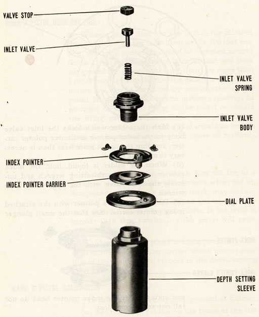
(c) Improper assembly of depth setting sleeve. See instructions noted in paragraph 13(n.)
(d) Binding of hydrostatic piston stem and key in the adjusting bushing due to corrosion. The practice of using Polar Type, Rust Preventive Compound, Navy Department Specification 52-C-18, Grade II, on overhauled pistols should help to control this condition.
130
Piston cross section.
(e) Displacement of the index pointer, at depth setting, with respect to its original calibrated position on the index pointer carrier. This is caused by failure to lock the index pointer screws securely with solder on the Mark 6 Pistol and Mark 6 Mod. 1 Pistol of early manufacture. Failure to tighten set screws securely on Mark 6 Mod. 1 Pistols having this type of fastening will permit index pointer to move from its originally calibrated position.
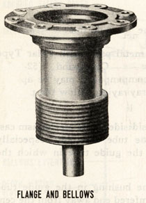
(f) Leakage at soldered joint between bellows and hydrostatic pistol and bellows and bellows extension.
131
(g) Binding of hydrostatic piston stem in bore of guide tube on Mark 6 Mod. 1 pistol. Action has been taken to eliminate this defect in recent manufacture by reducing the diameter of the end of the hydrostatic piston stem.
(h) Seating of the ball valve in deep firing mechanism of Mark 6 Mod. 1 Pistol when pointer is set at "0-300." Usually this is caused by end coils of valve spring not being properly set down. (i) Depth setting spring has become "set," due to prolonged compression.
CAUSES AND FAILURE AT 500 FOOT SETTING
2. The most common causes of failure of Mark 6 Mod. 1 pistols to operate satisfactorily when subjected to standard functional test at 500 ft. setting (Chapter V, Paragraph 8) are:
(a) Leakage past the dial plate gasket. This may be due to failure to securely tighten the dial plate lock ring. After screwing this ring into place with the dial plate lock ring wrench the ring should be set up by use of a drift.
(b) Leakage past the ball valve in deep firing mechanism. The edge of the hole in the valve seat, against which the ball is pressed by the valve spring, is very slightly beveled. Imperfections in this beveled edge may cause leakage.
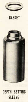
(c) Leakage through seal between neck of depth setting sleeve and dial plate. This may be caused by failure to screw deep setting mechanism tightly into place. Improperly fitting gasket or one not correctly assembled would also permit leakage at this point.
(d) Leakage past the gland around valve seat in deep firing mechanism. This may be caused by failure to tighten the gland nut securely.
(e) Chips of metal or dirt in valve seat.
132
WHEN A PISTOL DOES NOT FIRE
3. When a pistol does not fire within the allowed pressure limits on the initial test at the 100 foot setting, the firing operation should be repeated several times. If the firing pressure is consistent and does not exceed the allowed pressure limits by more than 5 psi it may be assumed that the defect is of a minor nature and can be corrected by recalibration of the pistol. However, should erratic pressure readings be recorded on repeated firing of the pistol or should the firing pressures exceed the allowed pressure limits by more than 5 psi the pistol should be broken down for examination as to the cause of malfunctioning.
CALIBRATION
4. A depth charge pistol, which does not fire at a pressure within the allowed tolerance when the index pointer is set at the 100-foot mark, may be calibrated if the error does not exceed the tolerance by more than 5 pounds per square inch. If the error is greater than this, overhaul of the pistol will probably be necessary.
5. Calibration of the pistol is made possible by the slots in the index pointer carrier which permit rotation of the pointer with respect to the depth-setting sleeve.
MARK 6 PISTOL CALIBRATION
6. To calibrate a Mark 6 pistol, proceed as follows:
(a) Set the index pointer on the pistol at the 100-foot mark. Place the pistol in the testing set and determine the firing pressure as directed in Chapter V.
(b) Remove the pistol from the testing set and cock the firing plunger.
133
Depth index pointer set to 100.
(c) Melt the solder which locks the inlet valve body to the index pointer and index pointer carrier, avoiding the use of more heat than is necessary to melt the solder.
(d) When the solder is liquid, hold the index pointer with the depth-setting wrench and unscrew the inlet valve with the inlet valve body wrench.
(e) Remove the index pointer with the attached index pointer carrier. See that the small plunger
and spring under the index pointer head do not fall out and become lost.
(f) Take out the two screws that secure the index pointer to the index pointer carrier and separate these pieces. It will probably be necessary to use heat to melt the solder that holds these parts together. Clean off all of the solder remaining on
134
Pistol parts.
135
the parts removed from the pistol.
(g) If the pistol does not have a 75-foot setting (Ordalt No. 1254) or is not provided with safe setting lock (Ordalt No. 1735) these modifications should be made at this time.
(h) Reassemble the index pointer and carrier as they were before ; that is, with the marks on these parts in alignment. Fasten the two pieces together with the two screws provided. See that proper washers are under the screw heads.
(i) Place the index pointer assembly in position on the depth-setting sleeve. If the sleeve has not been disturbed, the index pointer will point at the 100-foot mark. If the sleeve has been disturbed, move the index pointer back to this mark.
(j) Remove the index pointer assembly and reassemble it with the spring and plunger in place in the index pointer. This can be done as follows:
(1) Stand the pistol on the centering flange.
(2) Place the plunger in a vertical position with the spherical end in the dial plate indentation adjacent to the 100 foot mark.
(3) Put a little grease or vaseline on the end of the index plunger spring and place it in the socket in the index pointer. The grease will keep the spring from dropping out when the index pointer is turned over.
(k) Place the index pointer assembly on the pistol and lower it gently into position. If the hole in the pointer (now occupied by the spring) is in line with the plunger, the parts will go together. If they do not go together, move the index pointer a trifle and try again. It is important that the plunger stay in a vertical position during this
136
re-assembly. When the index pointer is properly assembled, replace the inlet valve assembly.
(l) The pistol will now be in the same condition as it was before the disassembly except that the parts formerly locked together with solder will now be free.
(m) Loosen the two index pointer screws. Hold the index pointer at the 100-foot mark and, by means of the two screws, rotate the depth-setting sleeve a small amount clockwise if the firing pressure was less than 40 psi or counterclockwise if the firing pressure was greater than 49 psi.
(n) Tighten the index pointer screws and test the pistol to determine the new firing pressure.
(o) Repeat the foregoing procedure until the firing pressure is as close to 44.5 pounds as possible and is within the specified limits (40 to 49 psi).
(p) Tighten the index pointer screws and turn the index pointer to SAFE. Test the pistol with the index pointer at the 30-foot mark as a final check on the calibration. The pressure required to fire the pistol at the 30-foot mark is 10 to 15 psi. No adjustment is provided for calibrating the pistol at the 30-foot setting.
(q) Cock the pistol and leave it cocked. Lock the inlet valve body and the index pointer screws to the index pointer with spots of solder.
137
MARK 6 MOD, 1, PISTOL CALIBRATION
7. While the procedure for calibration of Mark 6 pistol is generally applicable to the Mark 6 Mod. 1 pistol, additional instructions are necessary due to the leak proof features and other slight modifications of this pistol. The following instructions are given for the Mark 6 Mod. 1:
(a) The index pointer plunger in the Mark 6 Mod. 1 pistol projects through the top of the pointer lug and it is staked to hold it in place. Therefore, the instructions or comments pertaining to the plunger noted in paragraph 6 (e), 6 (j), and 6 (k) do not apply.
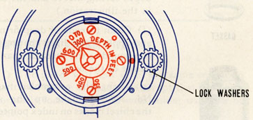
(b) The index pointer and index pointer carrier are locked together with set screws and external-internal type lock washers are fitted on round head brass screws. This method of securing the parts eliminates locking by solder and it is used on pistols of recent manufacture. In such instances it will be obvious that the instructions and comments noted in paragraph 6(c), 6(d), 6(f), and 6(g) are appropriately changed to fit the circumstances. Loosen the set screw in the deep firing mechanism body but do not unscrew the mechanism.
138
(c) Whenever it is necessary to recalibrate a Mark 6 Mod. 1 pistol on which the index pointer screws and deep firing mechanism are locked in place with solder, the complete depth setting sleeve-dial plate sub-assembly should be removed from the pistol after the solder has been melted and the deep firing mechanism unscrewed.
(d) Take out, the two screws that secure the index pointer to the index pointer carrier and separate these pieces. It will probably be necessary to use heat to melt the solder that holds these parts together. Clean off all the solder remaining on the parts removed from the pistol.
(e) Install a new gasket between the neck of the depth setting sleeve and the dial plate (as shown in the illustration.)
(f) Clean threads of deep firing mechanism body and apply a new light coating of joint and thread compound to the threads, shank, and underside of flange of the body.
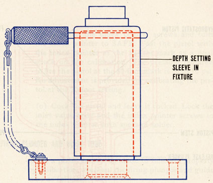
(g) Using the assembled fixture (BuOrd Dr. No. 389098) make up the sub-assembly with the chisel marks on index pointer and index pointer carrier in alignment. Locate the hole in dial plate in line with, and 180 degrees from the "V" on index pointer.
(h) Place a new dial plate gasket in position on the pistol carrying flange.
(i) Now test the sub-assembly as noted in paragraph 16 and replace it in the pistol. This is done by lining up the "V" on index pointer with 30 foot mark on carrying flange and then turning the subassembly clockwise two complete turns. Screw on the dial plate lock ring and seat it firmly with a drift.
139
DEPTH SETTING ASSEMBLY FIXTURE
(j) The pistol will now be in the same condition as it was before disassembly except that the parts formerly locked together with solder will now be free.
(k) Loosen the two index pointer screws. Hold the index pointer at the 100-foot mark and, by means of the two screws, rotate the depth-setting sleeve a small amount clockwise if the firing pressure was less than 40 psi or counterclockwise if the firing pressure was greater than 49 psi.
(l) Tighten the index pointer screws and test the pistol to determine the new firing pressure.
(m) Repeat the foregoing procedure until the firing pressure is as close to 44.5 pounds as possible and is within the specified limits (40 to 49 psi).
140
141
(n) Tighten the index pointer screws and turn the index pointer to SAFE. Test the pistol with the index pointer at the 30-foot mark as a final check on the calibration. The pressure required to fire the pistol at the 30-foot mark is 10 to 15 psi. No adjustment is provided for calibrating the pistol at the 30-foot setting.
(o) Cock the pistol and leave it cocked. Lock the inlet valve body and the index pointer screws to the index pointer with spots of solder.
OVERHAUL FIRING PLUNGER AND GUIDE TUBE
8. If a pistol cannot be made to function properly by calibration, overhaul the firing plunger and guide tube as follows:
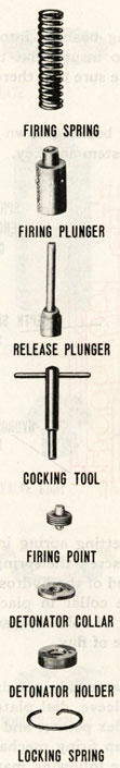
(a) Remove the detonator holder locking spring, the detonator holder, and the detonator collar. Remove the firing plunger by firing the pistol in the testing set. Use a piece of wood to absorb the blow of the firing plunger. Remove the guide tube bushing follower and the guide tube bushing.
(b) Disassemble the firing plunger. Use a small sharp chisel to chip out the metal of the plunger which is staked over to lock the firing point in place.
(c) Unscrew the firing point with the wrench provided. Remove the spring and the release plunger. See that the three balls do not fall out and become lost.
(d) Examine the release plunger for burrs and ball indentations. If the plunger is in any way defective and cannot be reconditioned readily, replace it with a new one.
142
143
(e) Place the release plunger in position in the firing plunger and test it for freedom of motion, up and down and turning. If there is binding, use a fine file to remove any burrs on the release plunger. Do this until the release plunger moves freely in the firing plunger. Do not increase radius of ball release shoulder. This radius is critical and should be 0.02 inches, maximum.
(f) Examine the balls to see that they are in good condition. If they are peened in their sockets tight enough to bind the release plunger, push them outward until the release plunger is free. Clean the release plunger and firing plunger after working on them.
(g) Examine the guide tube bushing and see that the inside edge, where the firing plunger balls rest, is in good condition. If there is any doubt about the condition of the guide tube bushing, replace it with a new one.
(h) Reassemble the guide tube bushing and firing plunger and test its operation as directed in Chapter V, paragraph 6.
COMPLETE OVERHAUL OF PISTOL
9. If a pistol does not operate properly after the above operations have been completed, it will be necessary to overhaul the pistol completely. To do this first disassemble the firing plunger assembly as directed above. Then set the index pointer at 30 foot mark and proceed as follows:
(a) Melt solder lock on index pointer screws and inlet valve body of Mark 6 pistol and remove inlet valve. Take off index pointer and index pointer carrier. Separate these two parts as noted in paragraph 6(f).
144
145
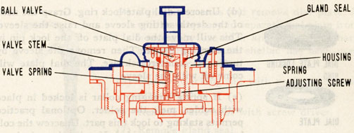
DEEP FIRING MECHANISM MK 6 MOD. 1
(b) Melt solder lock on index pointer screws and deep firing mechanism body of Mark 6 Mod. 1 pistols which have this construction. Remove deep firing mechanism, index pointer, and index pointer carrier. Separate the latter two parts as noted in paragraph 6(f).
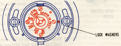
SET SCREWS AND LOCK WASHERS MK 6 MOD. 1
(c) Remove self locking cup point set screws in index pointer, and deep firing mechanism body flange and remove round head brass screws in arcuate slots of index pointer. Unscrew deep firing mechanism and take off index pointer and index pointer carrier. This instruction applies to Mark 6 Mod. 1 pistols which have set screw locking feature.
146
(d) Unscrew dial plate lock ring. Grasp the neck of the depth setting sleeve and raise the sleeve. This will move the dial plate off the lock pin in the carrying flange. Then remove the sleeve by turning it counterclockwise. The dial plate will come off with the sleeve.
(e) If spring engaging collar is locked in place with solder, melt the solder. Optional practice permits staking to lock this part. Unscrew the collar with wrench provided. If collar is staked extra torque applied to the wrench handle will be sufficient to break the collar free. Remove the depth setting spring and adjusting bushing.
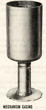
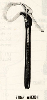
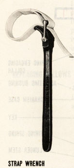
(f) Remove the mechanism casing from the carrying flange with the strap wrench provided. Although the part is locked by staking no difficulty will be encountered in breaking it free.
(g) The inlet valve assembly of Mark 6 pistol may by broken down by removing the stop (with wrench provided), the inlet valve, and valve spring.
(h) The disassembly of deep firing mechanism of Mark 6 Mod. 1 pistol is performed as follows:
(1) Submerge assembly in water up to a point just below the end surface of the spring adjusting screw and use a small torch to melt solder lock on adjusting screw. The water is used to dissipate heat which would have a harmful effect on the gland seal and spring.
(2) While solder is molten remove spring adjusting screw with screw driver.
(3) Remove spring and valve stem with attached ball valve.
147
(4) Take out screws and remove dial plate. It will be necessary to separate dial plate from housing by use of a knife or other sharp bladed tool because shellac has been used to seal paper gasket.
(5) Remove packing nut with packing nut and gland wrench.
(6) Remove valve seat with screw driver.
(7) Remove gland seal.
NOTE: Whenever a deep firing valve is broken down a new dial plate (paper) gasket and gland seal must be installed upon reassembly. If considerable application of heat was necessary to remove solder lock on adjusting screw a new valve spring should be used.
(i) The pistol is completely disassembled except for the hydrostatic chamber assembly, consisting of carrying flange, bellows extension, bellows, hydrostatic piston, stem, and key. Clean all parts thoroughly. Manufacturing specifications now require that all metal parts be coated with rust preventive compound. This practice is also in effect at depots performing reconditioning of pistols. Kerosene may be used to clean off this compound. Examine all working parts for wear, corrosion, distortion or other defects. Replace unsatisfactory parts. All parts of the original pistol were made of brass. Due to the need for conservation of this critical material it has been necessary to use steel as a substitute where possible. This situation will be reflected in the supply of spare parts. Also, for the purpose of expediting procurement, it has been necessary to allow changes in tolerances and form of parts. However, the requirement of interchangeability has not been impaired.
148
REPAIRING LEAKS
10. Replacing a bellows or repairing a soldered joint should be done by a mechanic experienced in soldering. Soldered joints must be watertight and mechanically strong. Use half-and-half solder (half - tin and half-lead) and a flux suitable to the metals being soldered. If an acid flux is used, clean the surface with a solution, such as soda water, to neutralize the acid after soldering. A non-corrosive flux may be used, provided the results obtained are satisfactory.
149
11. To determine where the pistol leaks, place the pistol carrying flange with the parts assembled on it in the testing set and subject it to about 30 psi air pressure. Provide a stop for the piston stem so that it cannot extend more than 1 inch when the pressure is applied. Apply a soap and water solution to the parts being tested to aid in locating leaks.
REPLACING BELLOWS
12. If a soldered joint leaks, repair it by resoldering. If the bellows leaks, it will have to be replaced, as follows:
(a) Unsolder the bellows from the bellow extension and hydrostatic piston. Use a small torch if available.
(b) Clean the edge of the bellows extension and the piston.
(c) Clean both end flanges of a new bellows.
(d) Place the bellows in position on the hydrostatic piston and crimp it in place.
(e) Solder the two together. Use a small torch if available. It should not be necessary to apply enough heat to loosen the silver-soldered joint between the piston and stem. However, this joint should be examined to see that it is watertight. See that the solder has not run either on the inside of the hydrostatic piston, where it will interfere with the free travel of the adjusting bushing, or on the outside of the piston stem, where it will interfere with the free motion of the stem in the guide tube.
(f) Crimp and solder the bellows extension to the top part of the bellows. It is important to locate the key in the piston stem so that it is directly opposite the dial plate lock pin in the pistol carrying flange.
150
151
REASSEMBLY OF THE PISTOL
To reassemble the pistol do this:
(a) Coat all metal parts with Polar Type Rust Preventive Compound (52-C-18) Grade II. This compound may be applied by dipping or spraying. Allow the parts to drain.
(b) Clean the inside of the mechanism casing and guide tube assembly, especially that part of the guide tube in which the bushing fits.
(c) Insert the bushing in the guide tube with the chamfered end away from the centering flange. Apply a light coat of red lead to the threads on the guide tube bushing follower and screw it in place with the tool provided. Remove excess red lead.
(d) REASSEMBLE THE FIRING PLUNGER as follows:
(1) Put lock balls in place. A small amount of vaseline on each ball will keep it from falling back within the plunger bore.
(2) Insert release plunger. Make sure that it is not burred or badly scarred.
(3) Insert firing plunger spring and screw firing point into place. Lock the firing point by staking or with a spot of solder.
(4) Try the release plunger by pushing it in by hand several times.
152
(e) Screw the mechanism casing on the pistol carrying flange and its assembled bellows extension, bellows, hydrostatic piston and stem. Tighten this securely with the strap wrench and stake it with a chisel.
Strap Wrench
(f) Insert the firing spring.
(g) Put the firing plunger into the guide tube in the following manner:
153
(1) Slide the firing plunger sleeve provided in the Mark 2 Mod. 1 tool set onto the firing plunger. Depress the release plunger so the balls can recede, and slide the sleeve over the balls.
(2) Start the firing plunger into the guide tube. As the plunger goes into the guide tube, the balls will be held in place by the guide tube bushing. And since the sleeve cannot pass the guide tube bushing follower, the sleeve will be automatically removed when the firing plunger is pushed into the guide tube bushing with the cocking tool. Do not cock the firing plunger at this time. As it is possible to put the firing plunger in backwards, be sure that the firing point is outward, toward the detonator holder.
(h) Replace the detonator collar, detonator holder and detonator holder spring.


 (b) Disassemble the firing plunger. Use a small sharp chisel to chip out the metal of the plunger which is staked over to lock the firing point in place.
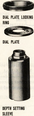 (d) Unscrew dial plate lock ring. Grasp the neck of the depth setting sleeve and raise the sleeve. This will move the dial plate off the lock pin in the carrying flange. Then remove the sleeve by turning it counterclockwise. The dial plate will come off with the sleeve.
 (4) Take out screws and remove dial plate. It will be necessary to separate dial plate from housing by use of a knife or other sharp bladed tool because shellac has been used to seal paper gasket.

 To reassemble the pistol do this: