|
Folks,
Depth Charges, Mark 6, Mark 6 Mod. 1, Mark 7, Mark 7, Mod. 1, OP 747, 1943, covers the U.S.N. depth charge from the first half of WW II.
We thank Ed Zajkowski for his generous loan of the original document used to create this online version.
Please report any problems with the Mail Feedback Form for correction.
Richard Pekelney
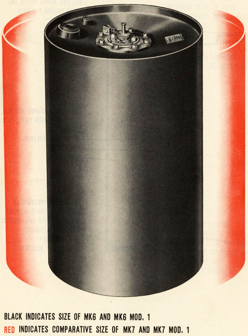
Webmaster
|
|
|

|
1
|
RESTRICTED |
ORDNANCE PAMPHLET No. 747 |
(FIRST REVISION)
DEPTH CHARGES
MARK 6
MARK 6, MOD. 1
MARK 1
MARK 1, MOD. 1
OPERATING AND MAINTENANCE INSTRUCTIONS

Department of the Navy
Bureau of Ordnance
22 DECEMBER, 1943
This publication is RESTRICTED and will be handled in accordance with Article 76 United States Navy Regulations 1920
|
2
|
|

|
3
|
|
NAVY DEPARTMENT
BUREAU OF ORDNANCE
WASHINGTON, D. C.
RESTRICTED |
22 December 1943 |
ORDNANCE PAMPHLET NO. 747, FIRST REVISION
DEPTH CHARGES, MARK 6, MARK 6 MOD. 1, MARK 7 AND MARK 7 MOD. 1.
1. Ordnance Pamphlet No. 747, First Revision, contains a
description and instructions for use of the Mark 6, Mark 6 Mod. 1, Mark 7 and Mark 7 Mod. 1 Depth Charges, with OCL M32-44 and OTI M2-44
2. This publication supersedes Ordnance Pamphlet No. 747 and its supplement, Ordnance Technical Instructions Numbers M2-43 and M6-43, Ordnance Circular Letters Numbers X-677, X-679, X-680, M10-42, M2-43, M4-43 and M11-43, and M23-43 and will become effective upon receipt. The latter publications should be destroyed.
3. This publication is RESTRICTED and is to be handled
in accordance with the provisions of Article 76, U. S. Navy Regulations, 1920.
4. It is not intended that this publication be carried in
aircraft for use therein.
|
4
|
Changes 1, pages 68a - 68w-3
Changes 2, page 97, figures 1-4
Changes 3, page 68, figure 1
Changes 4, page 3, page 68(c), par 12(c), (Change 1), page 90, figure 1
| Page |
| PART I - CHAP. I |
| SUMMARY AND EXPLANATION |
7 |
| What they are |
7 |
| How they work |
10 |
| Safety features |
10 |
| CHAP. II |
| PARTS |
17 |
| Weights of Depth Charge Parts 17 Cases |
21 |
| Pistols |
23 |
| How They Work |
26 |
| Mark 6 Pistol |
31 |
| Parts- |
33 |
| Depth controlling parts |
33 |
| Parts inside casing |
34 |
| Depth Setting Sleeve |
36 |
| Guide Tube |
38 |
| Locking Balls |
38 |
| Inlet Valve |
40 |
| Depth Settings |
41 |
| Index Pointer |
43 |
| Important Safety Devices |
43 |
| Safety Wrench Stop |
44 |
| Safe Setting Lock |
45 |
| Mark 6 Mod. 1 Pistol |
46 |
| Depth Setting Mechanism |
46 |
| Cylindrical Chamber |
48 |
| Spring Adjusting Screw |
48 |
| Valve Stem Hole |
48 |
| Valve Seat |
49 |
| Deep Firing Attachment |
50 |
| Index Pointer Plunger (Sticking) |
52 |
| Booster Extenders |
53 |
| How They Work |
56 |
|
|
| Page |
| Mark 6 Booster Extenders |
60 |
| Parts |
60 |
| Bellows |
62 |
| Spindle |
63 |
| Locking Balls |
64 |
| Mach. 6 Mod. 1 Booster Extender |
65 |
| Boosters |
66 |
| Mark 6 |
66 |
| Mark 6 Mod. 1 |
67 |
| Mark 6 Mod. 2 |
68 |
| Detonator Mark 1 Mod. 1 |
68 |
|
| CHAP. III |
| STOWAGE AND HANDLING |
69 |
| Cautions |
73 |
| When Depth Charges Are Ready |
73 |
| Cautions |
75 |
| Depth Charge Upkeep Routine for Ships |
76 |
| Pistol Routine-daily |
77 |
| Pistol Routine-weekly |
79 |
| Booster Extender Routine-daily |
80 |
| Interchangeability of Parts |
82 |
| Icing, Mark 6 Pistol & Booster Extender |
83 |
| Anti-freeze Mixtures |
83 |
| Introducing Mixtures |
83 |
| Failures |
85 |
| Sealing Substances |
85 |
| Booster Extender Care |
86 |
| Pistol Care |
87 |
| In Port Instructions |
87 |
| Ice Removal |
88 |
|
|
5
|
|
Page |
| CHAP, IV |
| SERVICE ASSEMBLY AND USE |
89 |
| TOOLS |
89 |
| Original Service Set (Mark 6 Pistol) |
89 |
| Packing Nut and Gland Wrench |
89 |
| Screw Driver for Mark 6 Mod. 1 |
89 |
| New Service Sets |
90 |
| Issuing Depots |
90 |
| Assembly Instructions |
91 |
| Booster & Booster Extender |
91 |
| Booster Extender Test |
93 |
| Detonator |
94 |
| Loading Depth Charges into Tracks or Projectors |
96 |
| Removing, Changing, Safety Forks and Pistol Covers |
97 |
| Setting Depth on Pistols |
99 |
| Setting Mark 6 Pistol |
99 |
| Setting Mark 6 Mod. 1 Pistol |
100 |
| Launching Charges from Release Tracks |
103 |
| Throwing Charges from Projectors |
103 |
| Underwater Action |
103 |
| Sinking Rates of Charges |
103 |
|
| PART II-CHAP, V |
| INSPECTION AND TESTING |
106 |
| General Instructions |
106 |
| Testing Sets |
107 |
| Pistol Tests |
107 |
| Tests Mark 6 & Mark 6 Mod. 1 Pistols |
109 |
| (with Mark 2 Mod. 1 set) |
109 |
|
|
|
Page |
| Tests Mark 6, Mark 6 Mod. 1 |
113 |
| (with pistol testing fixtures) |
115 |
| Deep Firing Test Mark 6 Mod. 1 Pistol |
117 |
| Booster Extender Tests Mark 6 & Mark 6 Mod. 1 |
121 |
| (test set Mark 2 Mod. 1) |
| Case Inspection |
123 |
| Booster Can Inspection |
127 |
| Detonator Inspection |
128 |
|
| CHAP, VI |
| REPAIRING AND OVERHAULING |
128-129 |
| Pistols |
126 |
| Causes of failure at 100 ft. setting |
128 |
| Causes of failure at 500 ft. setting |
131 |
| When failing to fire |
132 |
| Calibration |
132 |
| Mark 6 pistol calibration |
132 |
| Mark 6 Mod. 1 Pistol Calibration |
137 |
| Firing Plunger & Guide Tube Overhauling |
141 |
| Pistol, complete overhaul |
143 |
| Leaks, repairing |
148 |
| Bellows, replacing |
149 |
| Pistol reassembly |
151 |
| Depth Assembly Mechanism Mark 6 Mod. 1 Pistol |
159 |
| Frequency of Servicing |
163 |
| Booster Extender Overhaul |
165 |
| Disassembly |
165 |
| Assembly |
167 |
| Booster Cans, repairing |
170 |
|
| APPENDIX |
171 |
| List of Ordnance Sketches and Drawings |
171 |
| DISTRIBUTION |
173 |
|
|
6
|
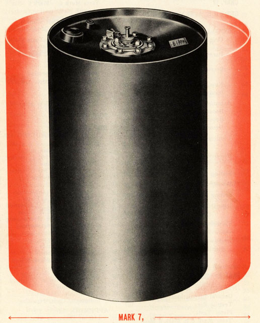
THE MARK 6 DEPTH CHARGE ASSEMBLED
|
7
|
|
PART I, CHAP. I
|
O.P. NO. 747 |
SUMMARY AND EXPLANATION
WHAT THEY ARE
1 THE MARK 6 DEPTH CHARGE
1. THE MARK 6 depth charge consists of a 300 pound charge of TNT which is fired by a hydrostatically operated pistol through the usual detonator booster train. The Mark 6 pistol has a depth setting range of 30 to 300 feet.
2 THE MARK 6, MOD, 1
2. THE MARK 6 MOD. 1 depth charge is identical to the Mark 6 except that it is fitted with a Mark 6 Mod. 1 pistol which has a depth setting range of 30 to 600 feet.
3 THE MARK 7
3. THE MARK 7 charge is exactly the same as Mark 6 in all principal parts EXCEPT that it has a larger case and contains 600 pounds of TNT instead 300 pounds.
4 THE MARK 7, MOD, 1
4. THE MARK 7 MOD. 1 charge is the same as Mark 7 EXCEPT that it is fitted with the Mark 6 Mod. 1 pistol.
|
NOTE: The above identifications will apply no matter what booster extender mechanism, booster or other parts are used to make up the completed depth charge assembly. |
|
8
|
|
|
9
|
COMPONENTS OR PARTS
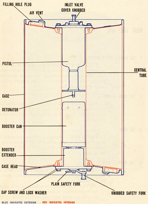
5. The above depth charges are made up of the following components:
(a) Case
(b) Charge
(c) Pistol
(d) Detonator
(e) Booster
(f) Booster Extender Mechanism
6. All of these charges measure 27.625 inches long. They DIFFER in weight and in diameter of case as follows:
(a) Mark 6 and Mark 6 Mod. 1 each weigh 420 pounds complete-and are 17.625 inches in diameter.
(b) Mark 7 and Mark 7 Mod. 1 each weigh 765 pounds complete-and are 24.875 inches in diameter.
HOW LAUNCHED
7. The Mark 6 and Mark 6 Mod. 1 charges can be dropped from all present types of U. S. Navy depth charge release tracks-and they can be fired from Mark 1 projectors (Y-Guns) and from Mark 6 or Mark 6 Mod. 1 projectors (K-Guns.)
8. The Mark 7 and Mark 7 Mod. 1 charges can be dropped from depth charge release tracks Mark 3, Mark 6, Mark 9 and Mods. They CANNOT be fired from types of projectors in service at this time.
|
10
|
|
HOW THEY WORK
|
O.P. NO. 747 |
FIRING AND SAFETY FEATURES
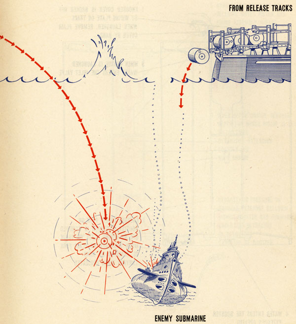
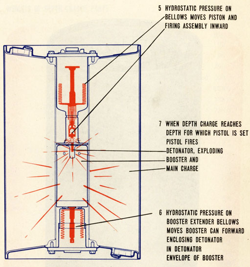
9. The depth charges are exploded at a predetermined depth by the hydrostatically operated pistol. The depth range depends upon the pistol used.
10. The chief safety feature for keeping charges from exploding until after they have entered the water, is the separation existing between the booster and detonator. Another safety feature is provided in the form of a pistol safe setting.
HOW THEY WORK
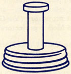
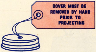
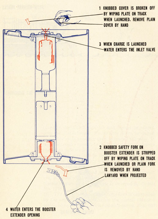
11. During shipment and stowage of a depth charge pistol, the inlet valve is closed by a plain safety cover screwed onto the valve body. When a charge is placed in a depth charge track this cover is replaced with one fitted with a projecting knob. The knob is broken off the cover by a wiping plate on the track when the charge is dropped, leaving an opening through which water can enter the pistol. If a charge is thrown from a projector, the plain cover is used. Before the projector is fired the plain cover must be removed by hand.
KNOBBED SAFETY COVER
|
11
|
|
PLAIN SAFETY COVER
12. Recently manufactured Mk. 6 pistols have nine possible settings of the index pointers, indicated by the figures 30, 50, 75, 100, 150, 200, 250, and 300 and the word SAFE stamped on the pistol flanges. The figures indicate the depths, in feet, beneath the surface at which a pistol will fire when the pointer is adjacent to any given setting. When a pistol is set at SAFE, it cannot fire if it has been properly assembled and calibrated.
13. As the charge sinks, water enters the pistol inlet valve at one end and the booster extender opening at the other
14. At a depth of 12 to 15 feet, hydrostatic pressure causes the booster extender to move the booster forward so that the detonator is housed in the booster can envelope. This action arms the depth charge which is now ready for firing.
15. A SAFE SETTING LOCK prevents the shock of gunfire, bomb hits, or underwater explosions from moving the index pointer off the SAFE setting. This lock consists of a short piece of No. 19 (".0358 dia.) copper wire rove through holes in lug of the index pointer and wrench stop. The ends of the wire are twisted together. The index pointer is thereby
|
12
|
|

LAUNCHING THE CHARGES
secured in the SAFE position and cannot be moved until the wire is broken. Round nose pliers, furnished in service tools sets, are used to install the wire. It is not necessary to remove the locking wire to change the index pointer from SAFE to a particular depth setting. The wire will be broken by the application of force to depth setting wrench handle. Whenever index pointer is reset to SAFE a new piece of wire is required. Wire, wound on a spool for convenient use, is included in service tool set. Modification of pistols in service and in store is covered by Ordalt No. 1735.
16. The depth at which the pistol fires is controlled by the setting of a pointer on the pistol. (Mark 6 pistol, 30 to 300 feet ; Mark 6 Mod. 1 pistol, 30 to 600 feet.)
|
13
|
|
|
14
|
|
|
15
|
|
|
16
|
|
|
|
|