1. CASES FOR MK. 6, MK. 6 MOD. 1, MK. 7, AND MK. 7 MOD. 1 depth charges are alike except for the minor details noted below and differences in dimensions.
MARK 6 AND MARK 7 CASES
2. The Mk. 6 and Mk. 7 depth charge cases are steel cylinders closed at the ends by steel heads welded in place. Set in each head of each case is an opening, closed by a pipe plug, through which TNT is loaded into the case. A central tube, extending longitudinally through each case, houses the pistol and booster-extender. Blank covers are provided to close the central tubes during shipment or whenever the pistols and booster-extenders are not installed.
22
The design of these cases has been modified as follows:
(a) One vent fitting installed near the filling hole in each head. This feature was added to allow air to escape when TNT is poured into the case. The vent plug must be screwed tightly into place when loading is completed.
(b) Circumferential bead adjacent to ends of case eliminated. This was done to permit use of the Mark 6 case in British depth charge release tracks.
3. To conserve critical material galvanized finish of cases has been discontinued. Cases are now finished as follows:
(a) All surfaces parkerized.
(b) Interior surfaces painted with 1 coat projectile cavity paint.
(c) Exterior surfaces and central tube painted with 1 coat zinc chromate primer.
(d) Exterior surfaces painted with 1 coat dark gray paint.
23
PISTOL
O.P. NO. 747
THE MARK 6 MOD. 1 PISTOL
24
25
PARTS MK. 6
26
PISTOLS
MARK 6 AND MARK 6 MOD, 1
4. THE MK. 6 AND MK. 6 MOD. 1 PISTOLS are the hydrostatically-operated firing mechanisms used in these depth charges. Each pistol consists essentially of housings for the operating parts.
(a) A flange with which the pistol is secured in a depth charge case.
(b) A bellows, spring, and setting device for determining the depth at which the pistol will fire.
(c) A firing plunger assembly for firing the detonator.
HOW THEY WORK
The principal difference between the Mk. 6 and the Mk. 6 Mod. 1 pistols is an added device in the latter design which increases its maximum operating range to 600 feet.
5. When a depth charge is DROPPED FROM A RELEASE TRACK, the knob on the inlet valve cover on the pistol is broken off by a wiping plate on the track. When the charge is THROWN FROM A PROJECTOR the plain cover is removed by hand immediately before the projector is fired.
27
HOW THEY WORK
REMOVE SAFETY COVER BY HAND
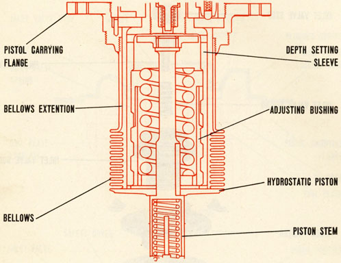
6. As the charge sinks, water enters into the space inside the flange, bellows and bellows extension through the inlet valve. Pressure in this space forces the piston to move inward, expanding the bellows and compressing the firing spring. Motion of the piston stem brings the spring-engaging collar against the depth-setting spring, the point at which this occurs being determined by the position of the adjusting bushing. Further inward motion of the piston takes place only as sufficient hydrostatic pressure is applied to compress the depth-setting spring between the spring-engaging collar and the inner end of the adjusting bushing. (When the pistol is set to fire at 30 feet, the pistol fires before the collar comes against the depth-setting spring. In this case, the entire resistance to motion of the piston is provided by the bellows, the firing spring and release plunger spring.)
7. As the piston moves inward it comes against the stem of the release plunger, forcing it inward and compressing the release plunger spring. When the recessed portion of the plunger comes opposite the locking balls in the firing plunger, these balls slip
28
clear of the guide tube bushing and into the plunger recess. This frees the firing plunger from the guide tube bushing, which previously prevented it from moving toward the detonator. The firing spring then snaps the firing plunger and firing point against the detonator, causing it to fire.
29
30
31
32
Parts callouts
33
DEPTH SETTING PARTS
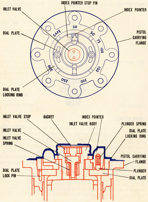
8. The depth setting parts of this pistol are housed in a casing. The flange of this casing secures the pistol assembly in the central tube of the depth charge case. The index pointer and dial are mounted on the outer surface of the flange to permit adjustment of the pistol when it is installed in a depth charge. An inlet valve assembly is mounted in the center of the index pointer assembly.
34
PARTS INSIDE THE CASING
9. Parts inside the casing are the bellows, a depth-setting sleeve, an adjusting bushing, a depth-setting spring, a piston stem. A collar is secured to the outer end of the stem in such a position that inward motion of the stem causes the collar to take up against the spring. After this has occurred further motion of the stem requires compression of the spring. A piston secured to the stem is also
35
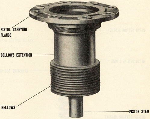
BELLOWS
BELLOWS
attached to the inner end of the bellows, while the outer end of the bellows is connected to the pistol flange by a bellows extension. The bellows and bellows extension provide a watertight, expansive housing for the depth-setting sleeve and spring and the adjusting bushing.
36
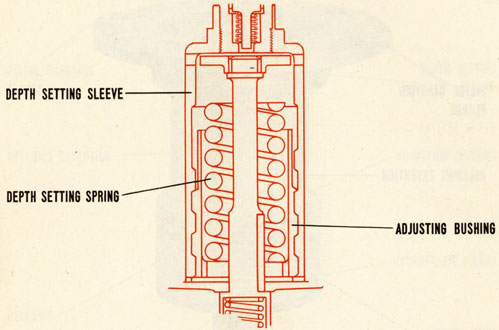
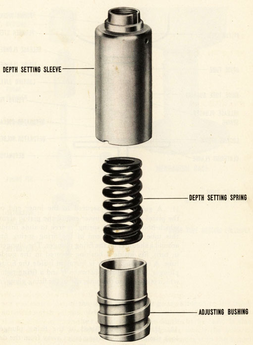
DEPTH SETTING SLEEVE
10. The depth-setting sleeve. which is attached to the index pointer and is free to rotate but not to move axially along the piston stem, is threaded internally to match external threads on the adjusting bushing. The bushing is keyed to the piston stem so that the bushing cannot rotate. Thus rotation of the depth-setting sleeve will move the adjusting bushing along the axis of the piston stem. The depth-setting spring is housed inside the adjusting bushing, between the inner end of the bushing and the collar on the piston rod. Therefore the position of the depth-setting bushing determines the distance the piston stem collar can move before it takes up against the depth-setting spring and the amount that this spring must be compressed before the striker is released.
37
38
GUIDE TUBE
11. A guide tube is secured to the inner end of the pistol casing. The inner end of the piston stem, which houses a firing spring, is free to slide inside this tube. The inner end of the firing spring fits around a shoulder on the firing plunger. The plunger, in turn, fits inside a bushing secured in the guide tube. A release plunger is installed inside the firing plunger, with a spring between it and a firing point which is secured to the inner end of the firing plunger.
LOCKING BALLS
12. Hardened balls fitted in the firing plunger lock the plunger and firing point away from the detonator. The detonator is secured in the inner end
39
of the guide tube. A flange is fastened to the inner end of the guide tube to center the pistol assembly in the central tube of the depth charge case. It also provides a flat surface against which the booster can rests when the booster-extender is in the armed position.
40
INLET VALVE
13. The inlet valve, mounted in the index pointer assembly, is primarily an anti-countermining unit. It consists principally of a spring-loaded valve installed in the port through which water enters the space inside the bellows and bellows extension. In normal operation the spring holds the valve clear of the seat and allows water to enter. Under abnormal pressure, however, such as might result from explosion of another depth charge nearby, the valve moves inward, compresses the spring, closes the port and prevents water from entering the pistol. When the pressure returns to normal the spring forces the valve open again.
41
DEPTH SETTINGS
15. Recently manufactured Mk. 6 pistols have nine possible settings of the index pointers, indicated by the figures 30, 50, 75, 100, 150, 200, 250, and 300 and the word SAFE stamped on the pistol flanges. The figures indicate the depths in feet, beneath the surface, at which a pistol will fire when the pointer is adjacent to any given setting. When a pistol is set at SAFE, it cannot fire if it is properly assembled and calibrated.
16. Older pistols did not have the 75-foot settings. If any such pistols are found in service, these settings should be added to them as directed by Ordalt No. 1254.
42
43
INDEX POINTER
17. The index pointer on a Mark 6 pistol is held in place on the index pointer carrier by the flange of the inlet valve body. It is secured to the carrier by two screws which pass through arcuate slots in the pointer. This arrangement permits calibration of the pistol during test by rotating the index pointer without disturbing the index pointer dial setting. After a pistol has been calibrated the screws are set up tightly. An alignment mark is made on that portion of the adjacent surfaces of the index pointer and index pointer carrier which are exposed by one of the wrench slots in the inlet valve body flange. (Then the screws and inlet valve body are locked in place with solder.) A spring loaded plunger is set in the under side of the index pointer. This plunger fits into indentations in the dial plate to hold the index pointer in place after it is set.
IMPORTANT SAFETY DEVICES
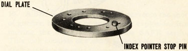
18. An index pointer stop pin is installed in the dial plate. The function of this pin is to terminate the rotation of the index pointer at the 30 ft. setting on one end of the range and at SAFE on the other end. Proper depth setting of the pistol requires that the index pointer shall be turned clockwise from 30 to SAFE and counter-clockwise from SAFE to 30. The index pointer must be rotated by hand or with standard depth setting wrench. Careful observance of these instructions will prevent shearing of stop pin and consequent accidental firing of detonator.