6
DESCRIPTION OF THE
MODEL X-1 DISTILLING UNIT
 
A. INTRODUCTION
 
6A1. Distiller types. At the date of this revision (Jan. 1955) there are several different types and models of distilling systems installed on submarines. They are:

a. Badger Model X-1, 1,000 GPD Vapor Compression Distilling Units. Two (2) units installed on each of the fleet type submarines and, with various alterations, on many of the snorkel submarines.

b. Badger Model V-1, 1,000 GPD Vapor Compression Distilling Units. Two (2) units installed on some of the later submarines, (SS563-568).

c. Badger Model WS-1,300 GPD Vapor Compression Distilling Units. One (1) unit installed on each "T" class submarine.

d. Cleaver-Brooks, 300 GPD Vapor Compression Distilling Units. One (1) unit installed on each of the "K" class submarines.

e. Badger Model Y-1, 1,000 GPD Vapor Compression Distilling Units. Two (2) units installed on SSN type submarines.

f. Griscom-Russell, 4,000 GPD low pressure two effect, soloshell type Distilling Unit. One (1) unit installed on SSN type submarines.

All of these units, with the exception of soloshell type, operate on the same basic principles, and since it is beyond the scope of this text to describe them all in detail, the Model X-1 has been selected as typical. It differs from the others only in minor details.

In the later sections of this text some of these differences will be described.

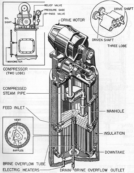
6A2. Model X-1. The Model X-1 vapor compression distilling unit is rated at 1,000 gallons of distilled water per day. It will produce 50 to 60 gallons of distilled water per hour from about 70 to 90 gallons per hour of normal sea water. The temperature of the distillate will be within 18 degrees F. of that of the sea water feed. The overflow will

  be about 30 degrees above the feed temperature. The unit was primarily designed to make cleaning more convenient.

Its main advantages over other models are:

a. It has a larger capacity.

b. It runs longer without cleaning.

c. It makes better battery water since it is constructed of nonferrous material, with the exception of 3/4-inch tubes in the heat exchanger, which are copper-nickel and tinned to prevent the contamination of condensate with nickel.

d. Its feed is inside the tubes; steam is outside the tubes.

e. It has short straight tubes. (This unit was designed originally to employ a mechanical cleaning method instead of acid cleaning. Submarines were equipped with mechanical cleaning equipment, and for a number of years the mechanical method of cleaning was the only method in common usage; now however, acid cleaning is used almost entirely, and it is expected that the mechanical cleaning gear will be deleted from the ship's allowance.)

f. It has an improved venting system.

g. It has more efficient auxiliary devices for control.

6A3. Difference between Model S and Model X-1 distilling units. The distillation process is the same in both units, the only difference being in mechanical design. In the Model S unit, the part played by the cones of coiled tubing, called the heat exchanger, is as follows:

a. Warming the feed.

b. Vaporizing the feed.

c. Condensing the vapor.

d. Cooling the condensate.

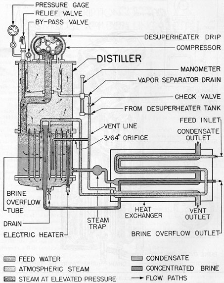
In the Model X-1 unit, the actions b and c are performed inside the main unit or evaporator in a space called the steam chest; actions a and d are performed in an external heat exchanger. Figure 6-1 is a cutaway view of the Model X-1 unit

 
(30)

Figure 6-1. Model X-1 distilling unit (cutaway view).
 
31

Figure 6-2. Model X-1 distilling unit (schematic view).
 
32

Figure 6-3. Piping arrangement, Model X-1 distilling plant (two units).

Figure 6-4. Schematic sketch for conversion of vapor compression distilling unit.
 
33

evaporator, while Figure 6-2 is a schematic diagram of a unit with external heat exchanger. The heat exchanger is illustrated in Figure 7-5.

The Model X-1 unit consists of two main parts the evaporator and the heat exchanger. The evaporator can be subdivided into three main elements-the steam chest; vapor separator; and the vapor compressor. The heat exchanger is essentially a double-pipe heater connected to the evaporator by piping.

6A4. Flow of water. (See Figure 6-2.) With the unit operating, the cycle will be as follows:

Cold sea water feed enters the heat exchanger where it is heated to about 190 degrees-200 degrees F. From there it goes into the evaporator and is injected down the downcomer. In the downcomer it mixes with the recirculating water and is heated to its boiling point. It then flows up the 3/4-inch tube where 1/2 to 2/3 of the incoming feed is vaporized at atmospheric pressure. The saturated atmospheric steam rises in the vapor chamber. The 1/2 to 1/3 of the feed remaining as liquid continually flows into the funnel, out of the evaporator and into the heat exchanger. This concentrated brine overflow is about 214 degrees F. As it flows through the heat exchanger it gives up its heat and is cooled to within 30 degrees F. of the cold sea water.

The atmospheric steam passes through the vapor separator where any entrainment separates out and is vented from the evaporator through a check valve except in those units equipped with conversions for operating with variable hull pressures. Where installed, this conversion substitutes a compound gage and pressure-static switch for the manometer, and the entrainment from the vapor separator is drained internally through a brass seal cup, and overflows with the brine. (See Figure 6-4.

  The manometer (or compound gage) indicates pressure inside the vapor separator, which is maintained at about atmospheric, except in the cases of conversions. The atmospheric steam then goes into the suction of the compressor where distilled water is dropped onto the rotating impellers to desuperheat the steam as it is compressed. The compressed, saturated steam is discharged at about 3 psi for a clean unit, through a pipe to the steam chest, into the space on the outside of the 3/4-inch tubes. As the 3-psi saturated steam condenses on the outside of the 3/4-inch tubes it drops down and collects on the bottom tube plate. Every time a pound of compressed steam condenses, approximately a pound of atmospheric steam is formed, thus keeping the compressor suction supplied with the correct amount of steam.

The condensate is drawn off through a steam trap and flows into the heat exchanger at about 220 degrees F. As it flows through the exchanger, it gives up its heat to the feed and is cooled to within about 18 degrees of the cold water feed. The steam trap prevents any steam from leaving the evaporator and automatically maintains the compressor discharge pressure at exactly the correct pressure so that all the steam compressed will condense in the evaporator, regardless of the conditions of the heating surfaces. Any air or noncondensable gases are vented from the steam chest through a small orifice. This air, plus a small amount of steam, flows into the vent line, carrying the entrainment into the heat exchanger. The steam condenses and gives up its heat to the feed.

6A5. Piping arrangement of Model X-1 distilling unit. The complete functioning of the Model X-1 distilling plant is shown in Figure 6-3.

 
34

Previous chapter
Previous Chapter
Sub Refrig. Home Page
Sub Distilling Home Page
Next chapter
Next chapter


Copyright © 2013, Maritime Park Association
All Rights Reserved
Legal Notices and Privacy Policy
Version 1.10, 22 Oct 04