CARE AND MAINTENANCE
OF THE MODEL S DISTILLING UNIT
A. RETARDING SCALE FORMATION
5A1. Scale formation. The coils of the distilling
unit gradually become coated with scale, and if
the operation is continued over too long a period
the accumulation of scale will tend to make the
tube cones stick together, and difficult to separate.
Since the tubes are made of comparatively soft
copper nickel, separating them cannot be accomplished without the certain danger of damaging
the cones.
5A2. Flushing during operation to retard scale.
After every 10 to 20 hours of continuous operation
all heaters should be turned on and the unit operated about 3 hours with maximum feed allowing
stable operation. If the compressor discharge
pressure continues to increase and does not come
down after flushing, more heaters should be used
and the overflow rate increased for the remainder
of the patrol or until such time as the flushing will
reduce the compressor discharge pressure.
Operators should endeavor to keep the compressor discharge pressure as low as possible. When
the pressure begins to increase and fails to return
to the initial operating pressure after flushing, the
overflow rate during operation should be gradually
increased by using more heaters and increasing
the feed rate. The unit should not be operated for
more than 22 continuous hours between flushings.
The periodic flushings will retard the increase
in operating pressure, but this will nevertheless
gradually rise. A rise in pressure of approximately 2 1/4 pounds from the initial operating pressure of 3 1/2 pounds may be considered safe. That
is, 5 3/4 pounds is the upper limit of compressor
gage pressure, at a compressor speed of 1100
rpm. In an emergency, 6 1/4 pounds may be used
as the upper gage pressure limit.
If the discharge pressure is allowed to increase
much beyond the pressures indicated, cleaning
by the acid method will be extremely difficult and
the type of scale formation will make it necessary
to disassemble and clean mechanically, which is
always difficult.
Every effort should be made to return to the
base or tender with distilling units operating at
5 3/4 pounds or less compressor discharge pressure.
Under these conditions the stills may be easily and
quickly cleaned by chemical methods without disassembly.
5A3. Flushing during shutdown period. The rate
of scaling will be retarded if the distilling unit is
operated at all times with a minimum of 20 gallons
per hour overflow, and, after the unit is secured,
flushed for a period of 1 1/2 to 2 hours with cold
sea water at a rate of approximately 60 gallons per
hour overflow, with the weir left filled with sea
water. Under the above conditions the distilling
unit should operate for a period of 350 to 400 hours.
B. THE TWO-LOBED ROOTS-CONNERSVILLE COMPRESSOR
5B1. Lubrication. The compressor is lubricated
from two reservoirs, one at each end. Each oil
reservoir is supplied with an oil level indicator
which has previously had the proper oil level
marked on the gage. The oil level should be
checked every 24 hours and oil added as needed
when the compressor is not running.
Two vertical 1/2-inch nipples with couplings
closed with two 1/2-inch pipe plugs are provided
for filling the oil compartment. The pipe plugs
are removed and oil poured into the couplings until
the proper level is reached. The oil may be drained
from the compartment by opening the 1/2-inch petcocks. Oil is retained in the oil compartment by
oil seal rings or packing glands.
The reservoir of oil at the pulley end of the
compressor lubricates the ball bearings by a
slinger ring attached to the drive shaft. The
(22)
reservoir of oil at the opposite end from the pulley
lubricates the timing gears and ball bearings at
that end of the compressor by the splashing of the
gears. All the bearings and gears run at a high
temperature, and no oil lighter than Navy Symbol
1150 (SAE 70) should be used in the Roots-Connersville compressor.
On the old type vapor compressors, steam seals
were used and leakage was carried away through a
drain pipe into the vapor separator and out
through the vent pipe. These seals were a source
of trouble and on the later type compressor they
have been replaced by packing glands. Steam
leakage is now prevented by the use of stuffing
box glands. These glands should be adjusted so
that they will be just tight enough to prevent leak
age. Excessive tightness will damage the packing and shaft sleeves, causing excessive heating
and the impellers will stick. The gland nuts must
be tightened evenly. When steam leakage cannot
be stopped by tightening the glands, new packing
must be installed. This may be done without dismantling the compressor. The nuts are loosened
first and then the gland is backed out.
Each gland is packed thus: one ring of Johns-Manville No. 360, three rings of Johns-Manville
No. 610, one ring of Johns-Manville No. 360.
Remove the first ring of No. 360 packing, using
the packing hook found in the spare parts box, and
one ring of No. 610. Insert two new rings of No.
610 and one ring of No. 360. Insert the gland and
tighten carefully. This should make the stuffing
box tight. However, if this is not satisfactory,
remove all five rings from the stuffing box and insert one ring of No. 360, three rings of No. 610 and
one ring of No. 360. Tighten gradually and evenly
as recommended. The packing gland which is
split may be removed from the shaft during the
packing operation if found necessary.
When a complete overhaul of the compressor is
necessary it must be removed from the distilling
unit.
5B2. Keeping oil out of the compressor. Should
oil for any reason get into the steam compressor it
will be left inside the 1/4-inch tubes of the heat
exchanger coils, causing the pressure to go up and
the heat transfer rate to fall off, besides contaminating the distillate with oil. A thin film of oil
may be noticed on the surface of the condensate.
To remove oil from the tubes, shut the unit down
and flush with feed water until the overflow feed
runs cool. Shut off the feed. Disconnect the condensate piping and make a connection to the condensate header with hose or piping, running the
open end to just below the compressor. Add about
two or three gallons of any pure oil solvent such as
naphtha, to this open end, completely filling the
tube bundle. Drain and repeat with the same
solvent. Reconnect the unit and continue operation.
5B3. Removing compressor from the unit. In removing the compressor, proceed as follows;
a. Remove the belt guard, loosen the variable
pitch drive, and take off the belts.
b. Disconnect the motor leads and take out the
bolts holding the motor support on top of the
compressor.
c. Remove the compressor lagging and after
draining the oil from the compressor take off all
the oil piping.
d. Remove the pressure gage and piping where
needed.
e. It is advisable to mark the oil piping so that
it may be put back in the exact location.
f. Take off all the nuts and lock washers attaching the compressor to the distilling unit, breaking
the gasketed joint by using jack bolts if available
and lift off the compressor.
NOTE. It is very desirable that any repairs to
a vapor compressor be done by a tender.
5B4. Disassembling compressor (new type).Figure 5-1 shows an exploded view of the two-lobed
compressor. Remove the motor-supporting base.
Remove the drive and cover, and then remove
the gear house cover. Mark each gear hub
and each shaft to be certain that the assembly of
the timing gears will be exactly in the same position as before. Also mark a gear tooth and its
mating groove to insure proper location of the
impellers and gears.
Remove the taper pin on the timing gear which
is pinned, using the taper pin punch in the compressor spare parts box.
CAUTION. Care should be exercised to avoid
bending the shaft by placing a heavy iron against
the hub of the gear when driving out the pin.
Remove the gears by means of the gear puller
provided in the compressor spare parts box. Remove the cap screws, and insert the 1/4-inch cap
screws provided in the spare parts box into the
23
bearing carrier. With the aid of these screws, take
out the bearing carrier. The carrier will contain
the bearings and oil slingers.
On the drive end of the compressor the bearing
lock nuts and then the cap screws must be removed.
Remove the oil slinger. By means of the 1/4-inch
cap screws the bearing carriers may be pulled out.
Remove the shims carefully.
Drive out the taper pins that locate the gear-end
head plate and remove all cap screws and lock
washers. By means of wedges, force the head
plate from the cylinder. The drive-end head plate
need not be removed.
Remove the glands from the shafts and take out
all the packing.
Pull the impellers and shafts from the drive-end
head plate.
Should it be necessary to replace the impellers
or gears in the compressor, a complete new assembly must be used because gears and impellers are
matched and cannot be used interchangeably. A
complete set is provided in the spare parts box.
5B5. Assembling the compressor. Push the shafts
with the impellers through the drive-end head
plates and then place the gear-end head plate
over the shafts and against the cylinders. Insert
the taper pins to locate the head plate correctly in
the original position. Insert the cap screws and
draw them up uniformly tight. Do not insert and
tighten one cap screw without installing and
tightening the other simultaneously.
Insert the bearing carriers with the oil slingers
and drive on the oil slingers using the drive tube
provided in the compressor spare parts box.
Drive the bearings on the shafts and into the
carriers against the oil slingers. On the gear end,
follow with the spacer collar.
Heat the drive shaft gear in an oil bath to a
temperature of about 250 degrees F. and quickly place
it over the shaft and press in the key. Set the
impeller shaft in the correct timing position, using
the gear spanner wrench from the spare parts box
to turn the gear. Heat the driven shaft gear to
about 250 degrees F. in an oil bath, then quickly place it
on the shaft and press in the taper pin. Check to
be sure that the taper pin is in the proper location
and will enter 80 percent of the distance by hand
and then drive it in firmly, placing a heavy iron
against the gear hub to prevent the bending of
the shaft while driving the pin.
On the drive end, after installing the carriers,
oil slingers, and bearings on both of the shafts,
and placing the collar and slinger plate on the
short shaft, tighten the lock nuts. By the use of
laminated shims the axial position of the impellers
must be adjusted to divide the total end clearance
of .012 inches as nearly equally as possible between
each end of the impeller and its head plate. The
laminated shims are .002 inches thick. Any extra
clearance should be left at the gear end when it is
not possible to set the impellers exactly in the central position.
The clearance on the driving face of the lobe of
the impeller on the drive shaft should be .016 inch
and on the back of the lobe .006 inch. If the impellers strike after being set for these clearances,
look for burrs, roughness, or particles of metal imbedded in the impeller.
If the impellers are not timed correctly with
the taper pin driven firmly into the driven shaft,
loosen the thrust bearing clamping plate and drive
out the taper pin. Place a thin strip of metal of
the proper thickness between the close impeller
lobes and, by use of the gear spanner wrench (from
the compressor spare parts box) placed on the
gears, turn the impellers in the proper direction
to cause the gear on the driven shaft to turn to
the correct location. The gear fit is too tight on
the shaft to permit movement with the spanner
wrench. Put pressure on the gear with the spanner wrench and strike the hub of the gear, causing
it to jump to a new position. The taper-pin hale
in the gear shaft may be reamed and the taper pin
driven in a little deeper. Tighten the thrust bearing clamping plate.
The impellers when correctly turned and located
maybe revolved easily by hand or spanner wrench.
CAUTION. Do not drive against the shaft or
any part mounted on the shaft after the thrust
bearing has been clamped in place by the clamping
plate.
Place safety wiring on the clamping plate cap
screws. Reinstall the gear housing and drive-end
housing, together with the drive shaft end cover
and oil slinger.
Repack all packing glands with the proper packing, install the packing glands, and tighten them
carefully.
Shellac the joint surfaces on the compressor and
motor-supporting plate, and then insert and
tighten the bolts uniformly.
C. CLEANING THE MODEL S DISTILLING UNIT
5C1. Methods of cleaning. The distilling surfaces
of the unit are cleaned by either of two methods:
(a) by using a muriatic acid (HCL) solution; or
(b) by scraping and wire brushing.
The approved method of cleaning is the acid
method. The acid method should be used only at
a base or alongside a tender, as it requires special
apparatus and an experienced crew. However, in
case the acid method is not available, or if the unit
is allowed to get too dirty for the acid method to
be effective, the unit must be disassembled and
cleaned mechanically.
5C2. Routine for acid cleaning. The Model S distilling unit may normally be cleaned by circulating a solution of 6.8 percent by weight of muriatic
acid (HCL) in water through the still.
A 6.8 percent by weight muriatic acid solution
is made up by adding 2 gallons of concentrated
commercial muriatic acid (20 degrees Baume) to 10 galIons of fresh water.
A charge of 30 gallons of the 6.8 percent muriatic acid solution is required for each still. It
should be circulated at a rate of about 60 gallons
per hour through the still.
The following is a list of the equipment needed
for acid cleaning both stills:
1 battery jar-about 45-gallon capacity
1 rubber container-about 5-gallon capacity
1 rubber measuring bucket
2 40- to 50-foot lengths of hose
4 4-foot lengths of hose
2 6-foot lengths of hose
2 6-inch lengths of hose
1 10-foot length of hose
1 12-foot length of hose
2 acid pumps
Miscellaneous brass pipe, fittings and valves,
several Stillson and monkey wrenches, hose
clamps, screwdriver, and pliers. Fresh water connection to deck of ship or dock.
12 gallons of HCL. (20 degrees Baume)
Proceed as follows:
a. Drain the unit and disconnect all piping at
the base comprising the feed, condensate, vent and
overflow.
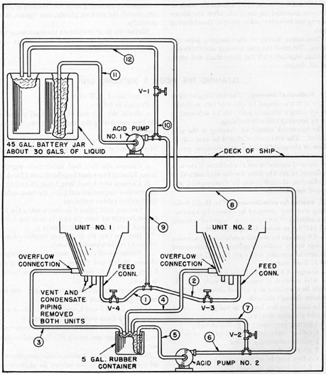
b. Connect a short length of pipe and a valve
to each feed connection (valves 3 and 4, Figure
5-2).
c. Connect the two feed connections together
into a T, using two 4-foot lengths of hose (1 and 2).
d. Connect two 4-foot long hoses (3 and 4) to
the overflow connection and place the open ends in
the 5-gallon rubber container.
e. Connect acid pump 2 as shown using the two
6-foot lengths of hose (5 and 7) and the 6-inch
piece of hose (6) and a T with valve 2.
f. Run the two 40- or 50-foot lengths of hose
(8 and 9) to the topside as shown.
g. Connect acid pump 1 using the two lengths
of hose, 10 feet and 12 feet (11 and 12), and the
6-inch length (10) connected to a T and valve 1
as shown.
h. Measure 30 gallons of fresh water into the
battery jar and mark the level.
i. Shut valves 3 and 4, open valve 1, prime acid
pump 1 with fresh water and start pump 1.
j. Open valves 3 and 4 until the water runs from
the overflow hose and nearly fills the 5-gallon rubber container.
NOTE. A man on topside should keep the water up to the mark in the battery jar as the units
are being filled. Each unit holds approximately
16 gallons when full to the operating level.
k. Shut valves 3 and 4.
l. Prime acid pump 2 and start with valve 2
open.
m. Open valves 3 and 4.
n. Adjust valve 2 so that the level in the 5-gallon
container is about constant. If pump 1 does not
25
Figure 5-2. Acid cleaning piping arrangement.
give sufficient water through the units with valve
1 wide open it may be partially closed.
CAUTION. Do not shut valves 3 and 4 until
valve 1 has been opened. The open end of hose 1
must not be below the level of the liquids in the
battery jar.
o. When water has been circulating freely about
15 minutes and all valves are adjusted, slowly add
12 gallons of 20 degrees Baume muriatic acid to the
battery jar. After all the acid has been added
circulate the acid solution through the units for
2 hours.
26
p. At the end of 2 hours of acid circulation,
place hose 8 overboard. When the level in the
battery jar is near bottom, fill the jar with fresh
water and keep it filled.
q. Circulate fresh water through the unit for
an hour. Secure the pumps, disconnect the hoses,
and drain the unit.
r. After every sixth acid cleaning, the shells of
the unit should be removed and the coils inspected
for scale. Until experience indicates otherwise,
the outer two or three coils should be removed and
inspected occasionally.
s. Reassemble the unit and fill with sea water.
NOTE. As the periodic inspections indicate,
the units should be completely disassembled and
the acid cleaning followed by a mechanical
cleaning.
5C3. Routine for mechanical cleaning. When
cleaning the Model S distilling unit by scraping
and wire brushing, it is necessary to disassemble
the unit. Use the following routine, taking particular care in handling the coils.
CAUTION. When disassembling the coils do
not lay the coils on their sides. Stack the coils on a
form, with the large ends down so as to prevent
the union ends from touching the floor or deck.
5C4. Disassembling the Model S distilling unit.
The disassembly procedure is as follows:
a. Drain. Drain unit completely of water.
b. Braces. Remove the braces at the bottom of
the unit.
c. Connections. Remove the thermometer bulb
and disconnect and remove all piping, comprising
the feed, condensate, vent and overflow pipe with
overflow cup.
d. Insulation. Remove the insulation from the
shell and keep it in a dry place.
e. Heaters. Disconnect the electric heater plugs
(heater plugs are the locking type and must be
turned about a quarter turn before disconnecting).
It is not recommended that the heaters be removed
at this time.
f. Glands. Remove the packing glands on the
vent and condensate pipes.
g. Flanges. Remove the small flange from the
bottom of the lower shell section, using the jack
bolts to break the gasketed joint. Take the two
large nits from the middle flange section and put
over the shorter studs on opposite sides of the
bottom flange; replace the two small flange nuts
and tighten to hold the cone sections together.
h. Lower shell. Remove all nuts from the middle flange of the shell and break the gasketed joint.
with the jack bolts provided. Take off the lower
part of the shell.
i. Upper shell. Remove the nuts from the top
flange and remove the upper half of the shell.
j. Conical shells. Remove the heaters and separate the two conical shells which make up the
overflow heat exchanger.
5C5. Cleaning the surfaces. a. Shells. Clean the
surfaces of both shells and inner cone by wire
brushing and scraping with soft copper scrapers
and wire brushes.
b. Coils. Insert the pins (found in the spare
parts box) into the clips, on each side at the top
of the vapor separator to support it, and to remove its weight from the coils.
Clean as much of the outer surface of the lower
coil as possible with the coil in place. Surfaces of
coils must be kept wet, otherwise the scale will be
hard to remove and the coils may not come apart
without damage. Disconnect the eight unions at
the top of the lower coil and one union at the
bottom. Remove the coil and its three spacing
cones, tapping with a wooden mallet if necessary.
(A union wrench and wooden mallet will be found
in the spare parts box.)
CAUTION. Great care must be taken not to
let the coils drop. Handle them carefully so that
the ends of the coils will not be damaged. A stand
should be available for holding the coils. If none
is available they may be placed in the lower shell
for protection.
Clean the inner surface and complete the cleaning of the outer surface.
Clean each succeeding coil in the same way.
c. Vapor separator. Remove the pins from the
vapor separator and wire brush the eight upper
headers and the inner cylinder of the vapor
separator.
(CAUTION. Never attempt to remove more
than one coil at a time from the distilling unit.
If a coil sticks, light tapping around the top third
of the coil with a wooden mallet will eventually
loosen it. Do not hit the coil too hard as this
may deform the copper nickel tubes or shape of
the coil.
27
338450 O-55-3
5C6. Assembling and testing the Model S distilling
unit. Proceed as follows:
a. Vapor separator. Place the vapor separator
in place and insert the pins to hold it.
b. First operation in replacing coils. Place
back into position the last coil removed.
NOTE. A small arrow stamped on the tab of
all coils aligns with the arrow stamped on the
upper head plate, below the pulley.
c. Upper and lower headers. Connect all the
unions of this coil to the upper headers. Connect
the lower discharge header to the small coil header,
positioning the discharge header as nearly vertical
as possible.
d. Routine for replacing coils. Plug up the
open unions on the lower discharge header. Connect a rubber hose to the outlet of the discharge
header and fill the tubes with fresh water until
water runs out of the open top unions. Inspect
the bottom union and small coil header for leaks.
If any union leaks, it may be corrected by lapping
its two contacting faces with the opposing parts
of a spare union; or by applying a film of white
lead on the union. In this operation it is possible
to check only the lower connections for leaks.
Remove the hose and top plug in the lower
header so that the next coil can be set in place.
Place the three spacer cones inside the next coil
and stand the small end of the coil in the steel coil
assembly cone which should be placed directly
below the unit.
Align the arrow on the coil in the assembly cone
with the arrow on the top flange, raising the coil
into position. Two men should lift the coil and
assembly cone, keeping the part unions on the upper headers from striking the part unions on the
coils as the coil is raised. A third man should
guide the lower end of the coil and assembly; as it
is raised and place a small hydraulic or screw jack
under the assembly cone, using a small piece of
wood between the bottom of the assembly cone
and the top of the jack. Raise the coil with the
jack until the union on the small coil header aligns
with the union on the discharge header. The coil
must be jacked up so that the bottom union makes
up exactly. The union should be started by hand,
making sure that the threads are not crossed.
Guide the coil so that the top unions do not strike
the headers.
NOTE. If no jacking cone is available, pressure may be applied to the thick circular bottom
header portion of the coil (3/8-inch diameter) using
wood to cushion the force of the jack.
CAUTION. Great care must be taken not to
put any pressure on the 1/4-inch tube that leads
from the 3/8-inch header at the bottom of the coils.
In most of the union nut wrenches a small slot has
been cut in the end. If absolutely necessary, fit
this slot over the back part of the union and align
the two parts of the unions before starting the
union nut by hand.
After the bottom union is tightened firmly, the
jack should be lowered. With no tension on the
bottom of coil it is now possible to rotate the large
(top) end of the coil so that the top unions will
make up. The coil should now be jacked up a
second time so that the top unions make up
squarely with no bending of the tubes. Tighten
the top unions and remove the jack.
e. Replacing remaining coils. Repeat the operations described in Section 5C6 on each of the
remaining coils and spacer cones in sequence.
f. Pins. Remove the pins from the top of the
vapor separator and allow the outer section of the
separator to rest in the first coil.
g. Testing the coil assembly. Test the coil assembly for tightness by connecting a rubber tube
to the outlet of the lower discharge header and
filling the entire bundle with distilled water (about
2 gallons). Elevate the open end of the rubber
tube above the upper unions on the coils so that the
tube assembly may be filled completely with water.
Leaks in the upper unions can be found and
corrected without removing the coils. Leaks in
lower unions will be indicated by water dripping
but this cannot be corrected without removing the
coils. For this reason, the lower unions and the 1/4-inch tubes, to which the lower unions are attached and brazed to the 3/8-inch bottom header
rings, should be tested as installed.
h. Gaskets. Use new flange gaskets where
needed. Extra gaskets are provided in the spare
parts box.
i. Upper shell. Place the upper half of the shell
in position, matching the arrows on the flanges.
Screw all nuts halfway onto the studs.
j. Lower shell. Place the lower cones in position with the proper gaskets and install the heaters.
28
Align with the arrows on the flanges and raise the
conical shells into position. Install the middle
flange nuts and tighten by hand.
k. Packing gland. Renew the packing in the
condensate manifold packing gland, using a piece
of 3/8-inch pipe instead of condensate pipe. Screw
the packing down hard and then back off on the
packing gland nut; leave the nut installed loosely
in the plate.
l. Pipes. Center the vent and condensate pipes
in their respective holes in the bottom cover plate.
Place the cover plate and supporting ring for the
lagging over the studs and secure with the proper
nuts, tightening firmly.
m. Shell flanges. Tighten the nuts on the upper
and middle shell flanges.
n. Packing. Install packing in the vent pipe
packing gland and tighten both the vent pipe and
condensate pipe packing glands.
CAUTION. The nut on the vent pipe has a
dual purpose: it acts as a packing gland nut, and
it insures a tight nesting of the ten coils. For this
reason, the vent pipe nut must be pulled up tightly.
A loosely nesting set of coils will cause too great
a difference between the condensate and feed temperatures, allowing excessive heat loss in the
condensate, and making it impossible to operate with
the proper amount of overflow.
o. Heaters. Install heater connections.
p. Braces. Install the braces at the bottom of
the unit.
q. Connections. Connect all piping.
5C7. Final testing of reassembled unit. The final
testing is done as follows:
a. Test for leaks. Start the feed pump and fill
the unit with water until it appears at the overflow
cup. Check the center and lower flanges for leaks,
also the packing gland nuts and the bottom of the
unit and threads where electric heaters are inserted. Test the heaters to determine whether or
not all are working, by noting the readings on the
ammeter.
NOTE. Do not install lagging until the unit
operates without leaking.
b. Insulation. Install insulation and check
heaters again to insure that all are connected
properly.
5C8. Repairing coils. Any possible damage to the
coils will require the use of silver solder. Cracks
occasionally are found in the brazing. Proper
brazing equipment and an expert mechanic are
required for this work.