MECHANICAL DETAILS OF THE
MODEL X-1 DISTILLING UNITS
A. GENERAL DESCRIPTION
7A1. Main unit or evaporator. This part of the
distilling system is referred to as the evaporator
because it is therein that the boiling and condensing, that is, actual distillation, takes place. The
evaporator, exclusive of compressor and motor, is
cylindrical in shape, with a 12- X 15-inch manhole
opening into the space above the tubes of the steam
chest. This cylindrical shell is covered with a
thick layer of glass wool insulation held in place
by a stainless steel jacket.
7A2. Steam chest. Inside the insulated jacket
the lower part of the cylinder is the steam chest,
where the sea water is vaporized, and distilled
water condensed. It consists of 334 admiralty
metal tubes, each 16 1/4 inches long with a 3/4-inch
o.d. These tubes are set side by side, as shown
in Figure 6-1, and enclosed in a shell. At the
top and bottom of the shell, the ends of these tubes
are expanded into holes in the tube sheets.
Standing among the tubes are two angular sheet
brass baffles 14 1/4 inches high. A pipe leads horizontally into the steam chest about 2 1/2 inches
from the top and bends down into the corner of
the inner baffle extending to 2 inches from the
bottom. This section of pipe, called the steam
chest vent, is pierced with nineteen 1/16 inch holes,
in two rows staggered along the side toward the
open part of the baffle. The baffles cause any non-condensable gases such as air to flow to the closed
end of the inner baffle, where they pass out through
the steam chest vent. See also Section 7A9.
The steam chest also contains the electric heaters, center downtake pipe, and overflow pipe.
7A3. Electric heaters. (See Figure 3-1.) The
eight electric heaters are contained in eight 1 3/4inch tubes which are spaced equally around the
outer diameter of the tube area of the steam chest.
The feed flows through these tubes, coming in
contact with the heaters.
7A4. Downtake. In the center of the bundle of
tubes is a 4-inch pipe with ends expanded into the
tube sheets. This is called the downtake. The
feed enters the evaporator through a pipe above
the steam chest, passing down through the downtake where it comes in contact with the concave
head which is bolted to the bottom of the steam
chest. The concave head is watertight, hence the
feed cannot pass beyond it. As more feed is supplied through the downtake pipe, it floods up
through the 342 tubes.
7A5. Feed. The feed inlet pipe in the evaporator
extends horizontally to the center and there
branches into a Y, the two ends of which tun down
and extend just below the funnel (Figure 6-1).
The Y-ends actually pass through the funnel wall.
The newly incoming feed pours into the downtake, mixing with the vaporized portion of the feed
already in the steam chest.
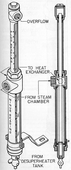
7A6. Overflow. The overflow is a 1 3/4-inch o.d.
pipe which is inserted inside the downtake (Figure 6-2). At the top of this overflow pipe is
brazed a 4-inch funnel. The top of the funnel is
2 inches above the top of the steam chest, maintaining the liquid level in the evaporator at this
height. The overflow pipe leads out through the
bottom of the evaporator to the heat exchanger,
where it gives up its heat, raising the temperature
of the incoming feed.
7A7. Portion of sea water distilled. About one-half to two-thirds of the feed is vaporized. The
remaining one-third overflows continuously into
the funnel, flowing out of the evaporator to the
heat exchanger giving up its heat to the incoming
feed water. From there it goes to the brine
receiver where it is drained to bilges or blown to
sea.
7A8. Vapor separator. The vapor separator is
an interior compartment, as in the Model S unit,
(35)
containing similar baffles (Figure 6-2). The vapor, entering at the top of the separator, descends
between the walls, and enters the separator chamber from where it travels upward to the compressor suction.
This circuitous passage of vapor causes any mist
of liquid that may be carried up by the vigorous
boiling action to separate from the vapor and fall
on the separator floor. In the original installations, the separated water drains out through the
separator drain pipe, manometer, and a check
valve into the evaporator vent pipe and thence
through the heat exchanger into the bilges. In
the units which have been altered for operation
while snorkeling, the drain from the separator
runs into a brass seal cup inside the unit and overflows with the brine.
In the original fleet type installations, the water
boils at substantially atmospheric pressure inside
the vessel. The contact with the atmosphere is
through the separator drain pipe and manometer.
The manometer (to be described later) is an instrument which indicates the pressure of the steam in
the vapor separator. If the pressure indicated is
above or below that found in the vessel, adjustment
of the heaters and/or the feed must be made.
In the converted units (see Figure 6-4) there
is no vent from the vapor space inside the unit
to the external pressure. The vapor pressure of
the boiling water is registered on a compound gage
which registers either vacuum (inches of Mercury) or pressure (inches of water). There is a
pressure-static switch connected to the gage piping
which is set to automatically control four (4)
heating elements to maintain the vapor pressure
at a positive pressure between six (6) and twelve
(12) inches of pressure.
This arrangement minimizes the effect of variable hull pressures on the operation of the unit.
7A9. The steam chest vent. A pipe leads horizontally into the steam chest about 2 1/2 inches from
the top and extends down into the steam chest to
within 2 inches of the bottom. This section of
pipe, called the steam chest vent, is pierced with
nineteen 1/16-inch holes, in two rows staggered
along the side toward the open part of the baffle,
as described in Section 7A2.
In this horizontal branch pipe, just outside the
evaporator, is a, union. Inside the pipe at this
point is a 100-mesh strainer and a diaphragm with
a 3/64-inch hole or orifice bored in its center. The
purpose of this small orifice is to vent air (which
is not condensable) from the steam chest. Normally only a very small amount of air is present,
hence the orifice is made small. The diaphragm
also prevents any drainage from the vapor separator drain pipe and manometer from entering
the distilled water through the steam chest vent,
in the ease of the units still not converted. See
Section 7A8.
7A10. Steam trap. The condensate in flowing
from the evaporator to the heat exchanger passes
through the steam trap. The steam trap prevents
any steam from flowing from the steam chest into
the heat exchanger. In so doing, it automatically
keeps the compressor discharge pressure at the
required value, sufficient to raise the condensation
point of the vapor and thus produce condensation
in the steam chest, regardless of the condition of
the heat transfer surface. Pressure within the
steam chest is necessary to provide a head against
which the compressor can work.
The steam trap takes the place of, and serves
the same purpose as the retarders in the Model S
unit.
The steam trap is of conventional type, roughly
spherical in shape, 4 3/4 inches inside diameter.
The condensate water enters horizontally at one
side and leaves at a point diametrically opposite.
The outlet is a short tubular extension with a flat
bolted cover, holding the connection and working
parts. The inside dimension horizontally from
inlet to cover plate is 5 1/8 inches.
Normally the steam trap is about half full of
condensate (water), the level of which is at the
top of the inlet opening. A spherical float connected by lever action to a pin valve in the outlet,
rises and falls with the condensate level, permitting the condensate to flow out only as fast as it
flows into the trap.
The action of the steam trap is as follows : The
condensate leaving the steam chest contains some
uncondensed steam mixed with it. In the steam
trap, the condensate fills only the lower half of
the enclosed space. The upper half is steam space.
When the waster drops below its normal level the
float drops with it, shuts the outlet valve, and
remains shut until the water level again rises.
There is a permanent bypass around the valve of
the steam trap, from the vapor chamber to the
36
outlet pipe. This bypass is 1/32 inch in diameter
at its smallest point and serves to prevent the
trap from becoming air bound. Before the bypass
valve on the distiller is shut, air is discharged
through the trap. If the permanent bypass is
plugged, the trap must be manually vented before
the unit will operate. On the top of the trap there
is a small valve which can be opened manually to
vent off large quantities of air.
The condensate normally flows from the steam
chest as it is formed. When the flow of condensate is restricted, pressure will build up in the
steam chest. This may be caused by the float being
stuck in the closed position or the orifice in the
bypass being plugged. If this condition occurs,
vent air from the steam trap by hand; if the pressure comes down and gradually builds up, it is a
good indication that the trap is not operating
properly. The unit should be secured and the
steam trap repaired.
7A11. Pressure gage. A 0- to 15-psi pressure
gage (Figure 3-3) is connected in the vapor compressor discharge line. The compressor pressure
gage indicates the discharge pressure of the compressor and the pressure at which the compressed
steam condenses on the outside of the tubes of the
steam chest.
Abnormal compressor discharge pressure is the
first indication of trouble. The normal compressor discharge pressure varies with the speed of
the compressor and the scale conditions inside the
tubes of the steam chest where the sea water is
vaporized. At constant compressor speed the
compressor discharge pressure is a direct indication of the amount of scale in the evaporator.
7A12. Relief valve. A relief valve (Figure 3-6) is
located on the upper head plate adjacent to the
compressor. It connects into the vapor compressor discharge line and prevents overloading of the
compressor motor. The valve is normally closed
under spring pressure set at 7 1/2 psi. It can also
be manually opened at any time by lifting the
lever. It is a safety valve, not a control valve.
7A13. Feed pump. The main sea water supply to
the unit is provided by a centrifugal type motor-driven feed pump, capable, of delivering 3 to 4
gallons per minute at 30 to 40 pounds gage pressure. The feed may also be from the variable
ballast tanks, or from the fresh water supply.
7A14. Water tanks. a. Distilled water. The distilled water, from both units, flows into a distilled
water receiver or tank (Figure 6-3), made of nonferrous metal, of approximately 46-gallon capacity. Air at 10 psi is admitted at the top of the
tank to give a head pressure. A petcock is provided for sampling. There is also a vent and a
drain to the bilge. Piping connections lead to the
desuperheater tank, to the battery water system,
and to the ship's fresh water system.
b. Brine receiver. The overflow of concentrated brine flows from the heat exchanger to a
brine receiver or tank, made of copper nickel, of
approximately 23-gallon capacity. Air at 30 psi
is admitted at the top of the tank to provide a
head when discharging overboard. There is a
vent and a drain to the bilge. The drain to the
bilge has a side-swing connection leading either
overboard or to fresh water storage when feeding
fresh water.
B. THE THREE-LOBED GENERAL MOTORS COMPRESSOR
7B1. Description. The General Motors vapor
compressor is of the positive displacement type
consisting of two rotors enclosed in a special compact housing designed for mounting on evaporators.
Each rotor has three helical lobes designed to
produce a continuous uniform flow of vapor. The
vapor enters the compressor housing at the bottom
and passes upward between the inner and outer
walls to the rotor chamber where it fills the spaces
between the rotor lobes as they roll apart. This
vapor is then carried by the rotors in the spaces
between the lobes around the cylindrical sides of
the housing, producing a pressure at the bottom as
the lobes roll together. Clearance is provided to
prevent the rotors from touching each other or the
surrounding housing.
7B2. Impeller gears. Opposite to the drive end,
a pair of one-to-one precision helical gears turns
the other impeller. The impeller gears run in an
oil bath in an oil-tight housing. The shafts pass
through packing glands in the housing.
37
7B3. Lubrication. The compressor is lubricated
from two reservoirs, one at each end. Each oil
reservoir is supplied with an oil level indicator,
which is attached to the compressor housing. The
oil level should be checked every 24 hours and oil
added as needed when the compressor is not running. The oil should be changed when the evaporator is cleaned.
Two vertical 1/2-inch nipples closed with pipe
caps (Figure 9-1, 89) are provided for filling the
oil compartments. Remove the pipe caps and
pour the oil into the nipples until the proper level
is reached on the gage.
The oil may be drained from the compartments
by opening the 1/2-inch plug cocks (Figure 9-1,
17).
Oil is retained in the oil compartments by the
use of slinger rings (Figure 9-1, 33 and 34) and
steam leakage is prevented by the use of stuffing
box glands (51 and 53).
These glands should be adjusted so that they will
be just tight enough to prevent leakage. Excessive tightness will damage the packing and shaft
sleeves, causing excessive heating and the impellers to stick. The gland nuts must be tightened
evenly.
The reservoir of oil at the pulley end of the
compressor lubricates the ball bearings by a slinger
attached to the driven shaft. The reservoir of oil
at the opposite end from the pulley lubricates the
timing gears and ball bearings at that end of the
compressor by the splashing of the gears.
7B4. Steam packing. When steam leakage cannot
be stopped by tightening the glands, new packing
must be installed. This may be done without dismantling
the compressor. First loosen the nuts
and back out the gland (Figure 9-1, piece 53).
Each stuffing box is packed with five rings of
Johns-Manville No. 350.
Remove all five packing rings, using the packing
hook found in the spare parts box. Install five
rings of No. 350 packing and install the gland.
Tighten gradually and evenly as recommended.
The split packing gland may be removed from
the shaft during the packing operation if it is
found necessary.
7B5. Compressor motor. A 7 1/2-hp motor with
necessary starting and protective electrical equipment is bolted on top of the compressor casing.
The drive to the compressor shaft pulley is by four
texrope V-belts.
7B6. Variable pitch drive. The drive pulley on
the motor is of the adjustable or variable pitch
type. The amount of variation of pitch is small- 5.400 to 6.600 inches pitch diameter of the pulley-and is intended only to adjust the tension of
the belts. The four left-hand sides of the pulley
grooves are attached to a sliding sleeve. Rotating
this sleeve moves the left-hand sides toward or
away from the four stationary right-hand sides.
Since the belt grooves are V-shaped in section, this
motion increases or decreases the pitch diameter.
Adjusting the variable pitch drive. Loosen the
setscrews on the sleeve. Turn the adjustable part
of the pulley with the special spanner wrench
(found in the spare parts box) until the belts are
at proper tension. The proper tension is that
which gives the belts, when running, a bow of
about an inch on the slack side. Then tighten the
setscrews.
C. CONTROL DEVICES ON MODEL X-1 DISTILLING UNIT
7C1. Manometer. The manometer (Figure 7-1)
is used on the units which have not been converted
for operation while snorkeling. It consists essentially of a brass framework holding two glass
tubes, one tube within the other. The inner tube
is smaller in diameter and approximately twice
the length of the outer tube. The outer and larger
tube is closed at the bottom and at the top it has
two openings, one of which is connected to the
drain from the vapor separator, the other being
the manometer drain to the heat exchanger. The
smaller or inner tube supported by the framework,
is open at both ends. The lower end is inside,
near the bottom of the larger tube; the upper end
projects out of the top of the outer tube and is
open to the atmosphere.
During the time that the distiller is in operation the manometer contains a small amount of
water normally supplied by drainage from the
vapor separator. During the warming-up period,
some water is drawn out of the manometer into
the vapor separator. Just prior to the time that
the distiller is ready to be cut in, the manometer
should be filled to its normal operating level,
38
which is at the top of the outer glass, with water
from the desuperheater tank. A pipe connection
and valve are provided near the bottom of the
Figure 7-1. Manometer.
manometer for this purpose. While the distiller
is in operation the upper surface of the water in
the outer glass tube is subjected to the pressure
from the vapor separator. This pressure may be
either above or below atmospheric pressure. Since
the upper end of the inner glass tube is open, the
water in the inner tube is subjected to two forces:
the vapor pressure caused by the boiling water in
the distiller, and atmospheric pressure. The
reading of the manometer is obtained by determining the difference in water level in the two
tubes.
When the level in the small inner tube is above
the level in the large outer tube, the pressure in
the evaporator is above atmospheric. When the
level in the small tube is below the level in the
large tube, the pressure in the evaporator is below
atmospheric. If the large tube is completely full,
its level is at zero and the pressure in the evaporator is indicated directly in inches of water by
the level in the small tube on the manometer scale.
The manometer is the primary guide in operating the unit, since it indicates exactly how the unit
is balanced. The manometer level remains constant if the unit is in exact balance. When the
unit is operating properly, the reading level is
behind the collar holding the vapor inlet. If the
reading level becomes visible above or below this
collar, the unit should be adjusted. On units
converted for operation with variable hull pressures, the manometer has been replaced with a
pressure actuated switch and a compound gage.
(See paragraph 7A8.) (See also Figure 6-4.)
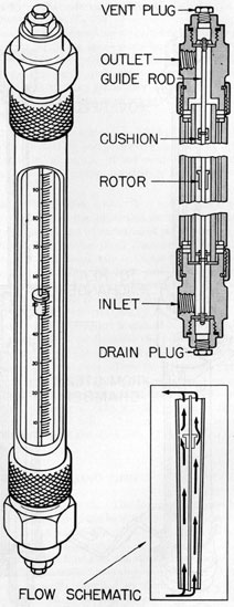
7C2. The rotameter. Two of these devices are
used for each distilling unit (Figure 7-2). One
is inserted in the incoming sea water line into the
heat exchanger to measure the rate of the feed
flow, which is normally 70 to 90 gph. The other
is in the outlet pipe from the heat exchanger to
the brine receiver to measure the rate of overflow,
which is approximately 1/3 to 1/2 of the total feed.
The rotameter is an upright pyrex glass tube
about 14 inches long (exclusive of end fittings)
through which the water flows. A metal casing
with a plexiglas window protects it. The tube
is tapered, with the small end at the bottom. Inside, a small metal rotor with a central hole slides
up and down on a guide rod, and is caused to spin
for free sliding by small vanes cut into its sides.
Since the tube is tapered, the space between the
39
rotor and the tube wall increases as the rotor rises,
permitting more water to flow through that space.
Therefore, the rotor will always rise to a height
corresponding to the rate of flow at any particular
time. A scale on the tube reads directly in gallons
per hour.
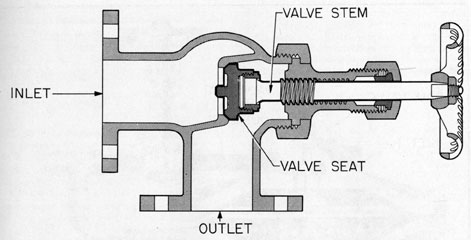
7C3. Bypass valve. This valve (Figure 7-3) on
the Model X-1 unit is located on top of the upper
head plate. It is not built into the head plate as
in the Model S unit, but is an individual device,
bolted on. It is a stop valve and when open, it permits the compressor discharge to return directly
into the vapor separator. It is opened when starting, and closed during distillation.
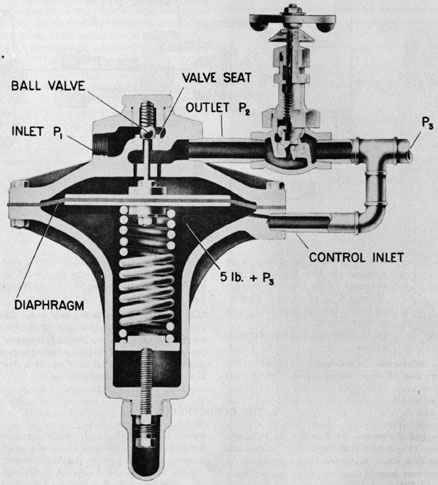
7C4. Feed regulating and flow control valves. In
the feed line, just after the water filters leading
to the heat exchanger, is the feed regulating valve
(Figure 7-4) and the flow control valve (Figure
3-9). These valves control the flow of incoming
feed water. The flow control valve is set to give
any desired flow through the feed rotameter. The
regulating valve then maintains the feed constant
at this rate regardless of feed pressure changes.
The flow control or feed valve is used as a variable orifice. Any similar type valve could be substituted but the adjustment is much finer if a flow
control type is used.
The regulating valve is a spring-loaded diaphragm type valve, similar to an ordinary reducing valve, having two watertight compartments
separated by the diaphragm. It is installed with
the spring and diaphragm below the feed line.
Connecting into the feed line is a ball type valve
with the lower or discharge side open to the compartment on top of the diaphragm and open to the
feed line just before the flow control valve. The
diaphragm acts on the ball to open or close the
ball valve. The water pressure present just before
the flow valve, is exerted downward on the diaphragm and tends to close the ball valve by displacing the diaphragm downward. The compartment below the diaphragm is connected into the
feed line just after the flow control valve. A coil
spring in this lower compartment exerts a pressure
upward on the diaphragm equivalent to 5 psi in
addition to whatever pressure is present in the
feed line just after the flow control valve. Thus
the pressure in the feed line just before the flow
control valve will always be exactly 5 psi more
than the pressure in the feed line just after the
Figure 7-2. Rotameter.
40
Figure 7-3. Bypass valve.
flow control valve. Once the flow control is set
at any given opening, the flow through it will
remain constant because of the constant pressure
drop through it, regardless of pressure fluctuations in the feed line before the regulating valve
or after the flow control valve.
The small spring on top of the ball serves to
keep the ball in place.
7C5. Other valves in the feed line. Between the
regulating and flow control valves, a relief valve
set at 50 psi is connected into the feed line of each
unit. A feed pump discharge gage is set into the
line beyond the feed water filters and indicates the
feed pressure just before the regulating valve.
7C6. Order of devices in the feed line. The devices of the feed line, starting from the hull, are
as follows: stop valve, Macomb strainer, feed
pump, filters (two), feed pump discharge pressure
gage, feed regulating valve, relief valve, flow control valve, and feed rotameter.
D. THE DESUPERHEATER
7D1. Desuperheater. An 8-gallon desuperheater
tank, fed by a pipe from the distilled water tank
(Figure 6-3), is supported above the units. A
water level gage is attached to the desuperheater
tank, and an overflow pipe leads to the bilge. From
the bottom of the desuperheater tank, a 1/4-inch
tube leads to each of the compressors and into the
impeller housings above the impellers. Valves in
these tubes are adjusted to cause the distilled water
to flow as drops, not as a steady stream on the impeller lobes. Since the drip is inside the compressors and hence not visible, a sight feed glass with
a glass window through which the water drops
may be seen passing, is inserted in each tube just
outside the compressor. In normal operation of
the units, the desuperheater flow is at a rate of 200
drops or more per minute. A rate of 200 drops per
minute is a very rapid one. It is the rate that
exists just before the flow becomes a steady stream
in the sight glass.
7B2. Need for desuperheating. When steam generated by boiling liquid at atmospheric pressure
and a temperature of 212 degrees F. is compressed mechanically to a pressure between 3 to 6 pounds, the
steam is superheated and reaches a temperature
of 285 degrees to 400 degrees F. in the compressor. If this compression takes place in the presence of water, the
water removes the superheat from the steam and
41
Figure 7-4. Feed regulating valve.
allows it to pass into the distiller at a temperature
of saturated steam, which is 222 degrees F. at 3 pounds
and 230 degrees F. at 6 pounds gage. Desuperheating is
needed for two purposes
a. Water from the desuperheater tank dripping
on the impellers keeps the impellers and their
shafts, cooled. This cooling action prevents too
great an expansion of the impellers by heat, thus
retaining the required clearance of the impellers.
It also prevents the shaft packing from getting too
hot, which would cause rapid deterioration of the
packing.
42
b. Better heat transfer is obtained from saturated steam than from superheated steam. A fast
heat transfer is necessary to assist in keeping the
feed water boiling; the quicker the steam condenses, the lower the pressure on the discharge
side of the compressor will be.
Distilled water must be used for this desuperheating process. Ordinary fresh water contains
various minerals and chemical compounds. These
substances, while harmless to human health, would
be deposited on the impellers (since only the water
vaporizes) and would gradually build up to a
thickness that would cause the impellers to bind.
E. HEAT EXCHANGER
7E1. Heat exchanger. The feed heat exchanger
is a preheater which warms the incoming sea water
feed. The sea water enters at ocean temperature,
which varies according to location and season. It
leaves the heat exchanger at about 200 degrees F. Hence,
when the feed enters the evaporator, it needs to
be raised only a few degrees more to reach the
boiling point. The construction of this heat exchanger, and a diagram of the flow paths through
it are shown in Figure 7-5.
The distilled water or condensate leaving the
steam chest reenters the heat exchanger, at about
the same temperature as the condensing steam in
the steam chest (220 degrees F. at 3 psi), passing countercurrent (that is, in the opposite direction) to the
feed flow, in order to assure the best heat transfer
from the hot outgoing distilled water to the cool
incoming feed, and thus warming the feed and
cooling the distillate or condensate. The heat exchanger is of the double tube type. It consists of
fifty 1 1/4-inches i.d., straight tubes, 45 inches
long; and fifty 3/4-inch o.d., straight tubes, 48
inches long. The 3/4-inch tubes are externally
finned with No. 18 gage copper nickel wire. There
are also six tube sheets, three on each end. In the
assembly of the heat exchanger, the large tubes are
arranged in a bank and inserted in the inner tube
sheets (Figure 7-5); the tubes are packed into
these tube sheets with fiber and metallic packing
to prevent leakage.
CAUTION. The metallic packing should not
be installed so that it is in contact with the fresh
water or condensate side of the heat exchanger.
The small tubes have their ends silver-soldered
into a bushing at each end. This assembly is inserted inside the larger tubes. The ends of the
small tubes with the bushing extend out of the
larger tubes about 1 1/2 inches on each end and
through the outer tube sheets. The bushing is
packed into these tube sheets. The tube sheet
cover plates seal the ends of the heat exchanger.
The outer tube sheets and the tube sheet cover
plates contain milled passages which direct the
flow of water. The entire tube bundle is enclosed
in a brass casing for protection.
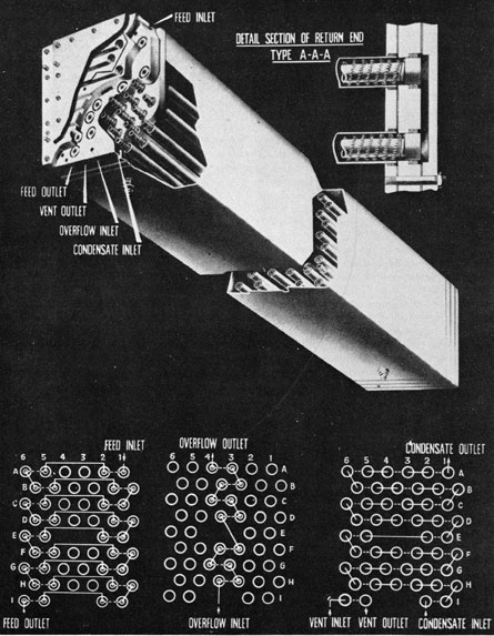
7E4. Flaw paths in the heat exchanger. There are
four distinct flow paths through the heat exchanger. The condensate flows through 48 large
tubes, around the smaller tubes. Steam from the
vent pipe and drainage from the vapor separator
flow through two large tubes around the smaller
tubes. Feed water flows through 36 of the small
tubes. The brine overflow from the steam chest
flows through 14 of the small tubes. The flow in
the large tubes is in the space left around the
small tubes. The small tubes are connected by
return headers at each end, and in such away as
to provide two separate longer paths of water
flow. The large tubes are likewise connected by
return headers at each end in such a way as to
provide two separate longer paths of water flow,
each completely separate from the others.
The flow diagrams in the lower right corner of
Figure 7-5 show these four separate paths. The
diagrams show the pipes as viewed from the inlet
and looking toward the rear or return end; that
is, the pipes are represented as circles. In order
to describe the flow paths in a simple manner, the
tubes are designated in accordance with the following plan.
The rows are designated by letters starting with
the top row. Capital letters refer to the large
tubes. Small letters refer to the 3/4-inch o.d.
tubes. The tubes in each row are designated by
numbers from 1 to 6 starting at the right. In the
diagram only the top row has the numbers; each
row is similarly designated, starting from the
right. Two diagrams are used in order to simplify the presentation of the four paths. In the
following description, the term goes forward
43
Figure 7-5. Heat exchanger.
means that the flow is away from the observer as
he looks at the flow diagrams in Figure 7-5; that
is, from the inlet and toward the return end. The
term comes back means that the flow is in the
opposite direction; that is, toward the observer, or
from the return end to the inlet end. When it is
said that the flow goes forward in a1, comes back
in a2, it is naturally understood that the flow
crosses from a1 to a2 in the return end header.
When it is said that the flow comes back to a2,
goes forward in a5, it is understood that the flow
crosses from a2 to a5 in the inlet end header.
Feed flow. The feed flows through 36 small
tubes, entering cold at the top of the heat exchanger. It goes forward in a1, comes back in
a2, goes forward in a5, comes back in a6, goes forward in b6, comes back in b5, goes forward in b2,
and comes back in b1. Continuing, it follows the
same route in rows c, d, e, f, g, h, and i, emerging
hot from tube i6 at the inlet end of the heat exchanger, as may be seen in Figure 7-5.
Overflow path. The hot brine overflow uses the
remaining 14 small tubes, entering hot at the bottom of the heat exchanger. It goes forward in h4,
comes back in h3, goes forward in g3, and comes
back in g4. Continuing, it follows the same route,
as may be seen in Figure 7-5, in rows f, e, c, b, and
a, emerging cool from tube a4 at the inlet end of
the heat exchanger.
Condensate path. The condensate flows in 48 of
the large diameter tubes, entering hot at the bottom
of the heat exchanger. It goes forward in I2,
comes back in I1, goes forward in H1, comes back
in H2, goes forward in H3, comes back in H4, goes
forward in H5, comes back in H6, goes forward in
G6, comes back in G5, goes forward in G4, comes
back in G3, goes forward in G2, comes back in G1,
and goes forward in F1. Continuing, it follows
the same route, as may be seen in Figure 7-5,
through the remaining rows. The condensate
emerges cool from tube A1 at the inlet end of the
heat exchanger.
Vent flow. Steam and noncondensable gases
from the manometer and steam chest flow inside
the remaining two large tubes in the bottom row,
where the; steam is condensed and the gases cooled.
They enter hot and go forward in 16; and come
back in 15, emerging somewhat cooled from tube 15
at the inlet end of the heat exchanger.
7E3. Step-wise heat transfer. It may be noted
that the heat transfer takes place in a step-wise
manner in the heat exchanger. The hot condensate gives up some heat to the feed in tubes I2, I1,
H1, and H2; picks up a little heat from the overflow in G4, and G3; gives up heat to feed in G2, G1,
F1, and F2; and continues this step-wise heat
transfer throughout its path to A1. The loss of
heat from condensate to feed, however, is always
much greater than the gain of heat from overflow
to condensate, so that the total result is a large heat
transfer and overflow to feed.