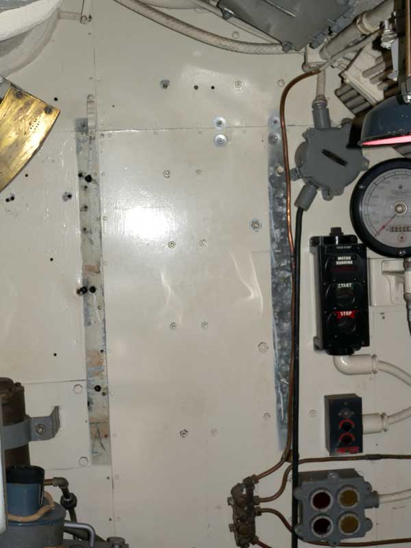
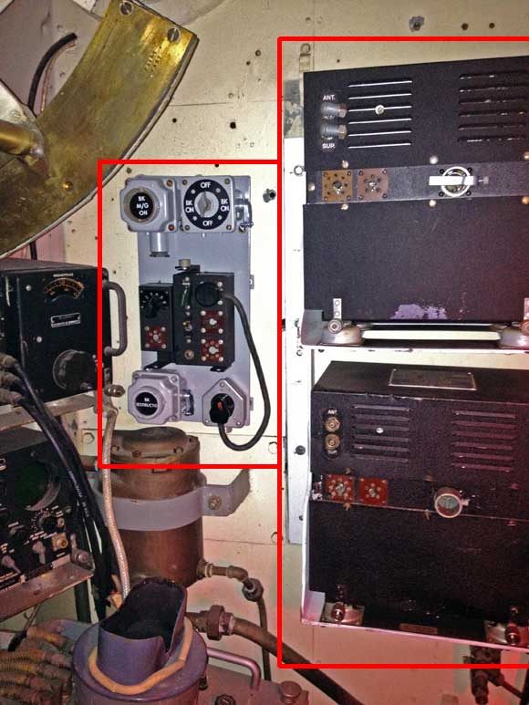
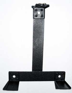
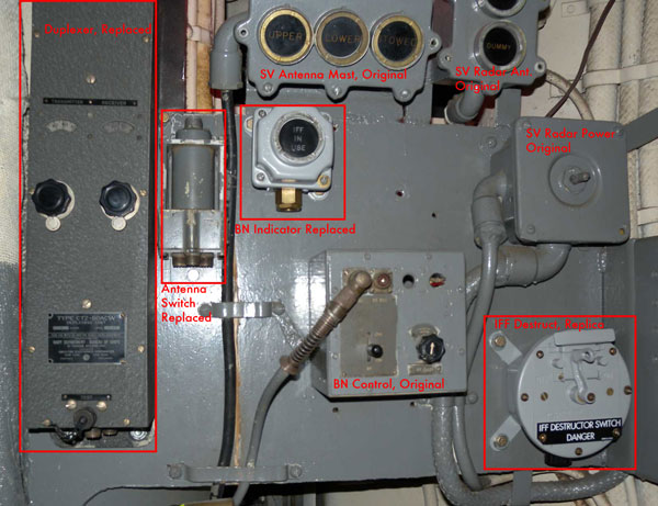
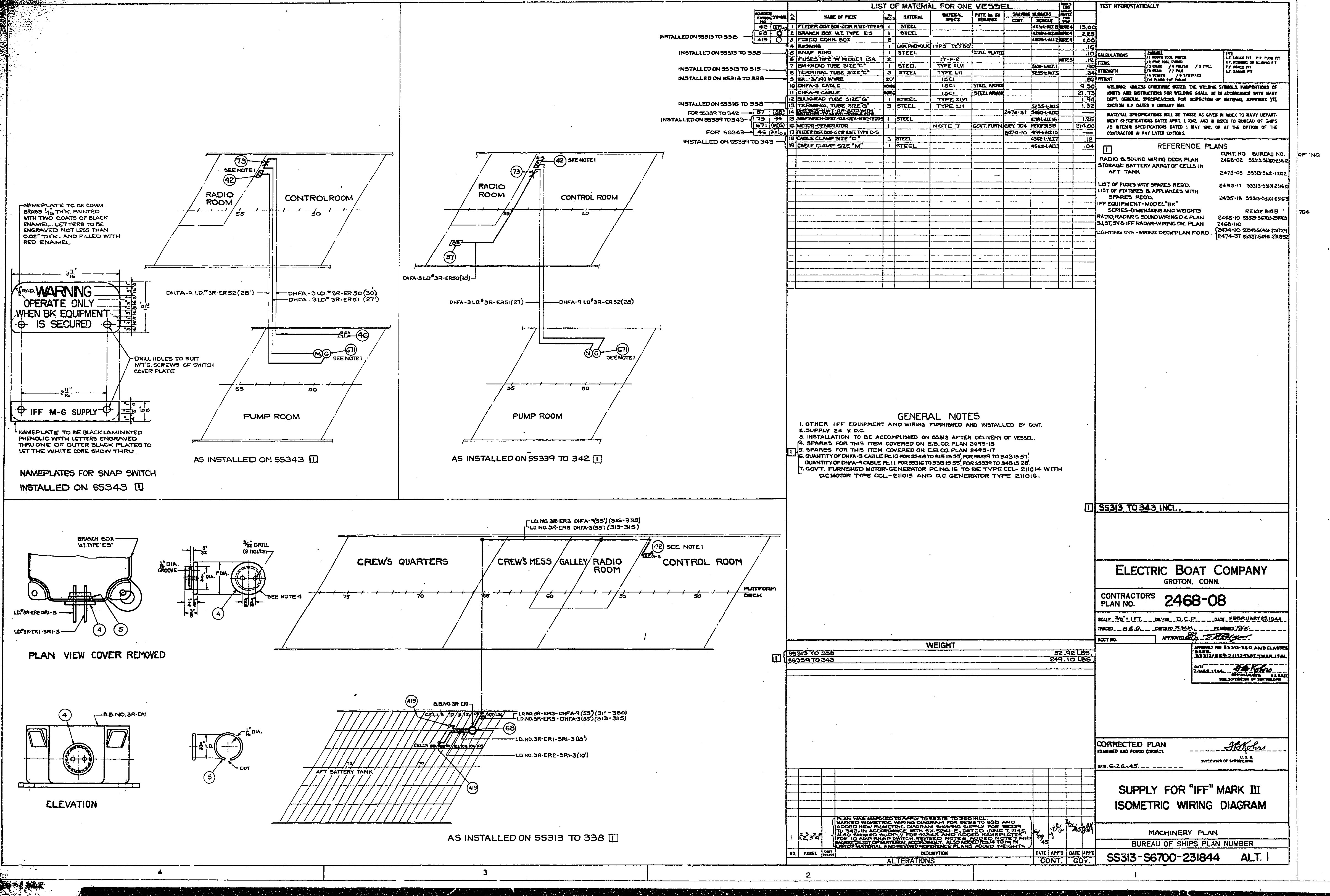
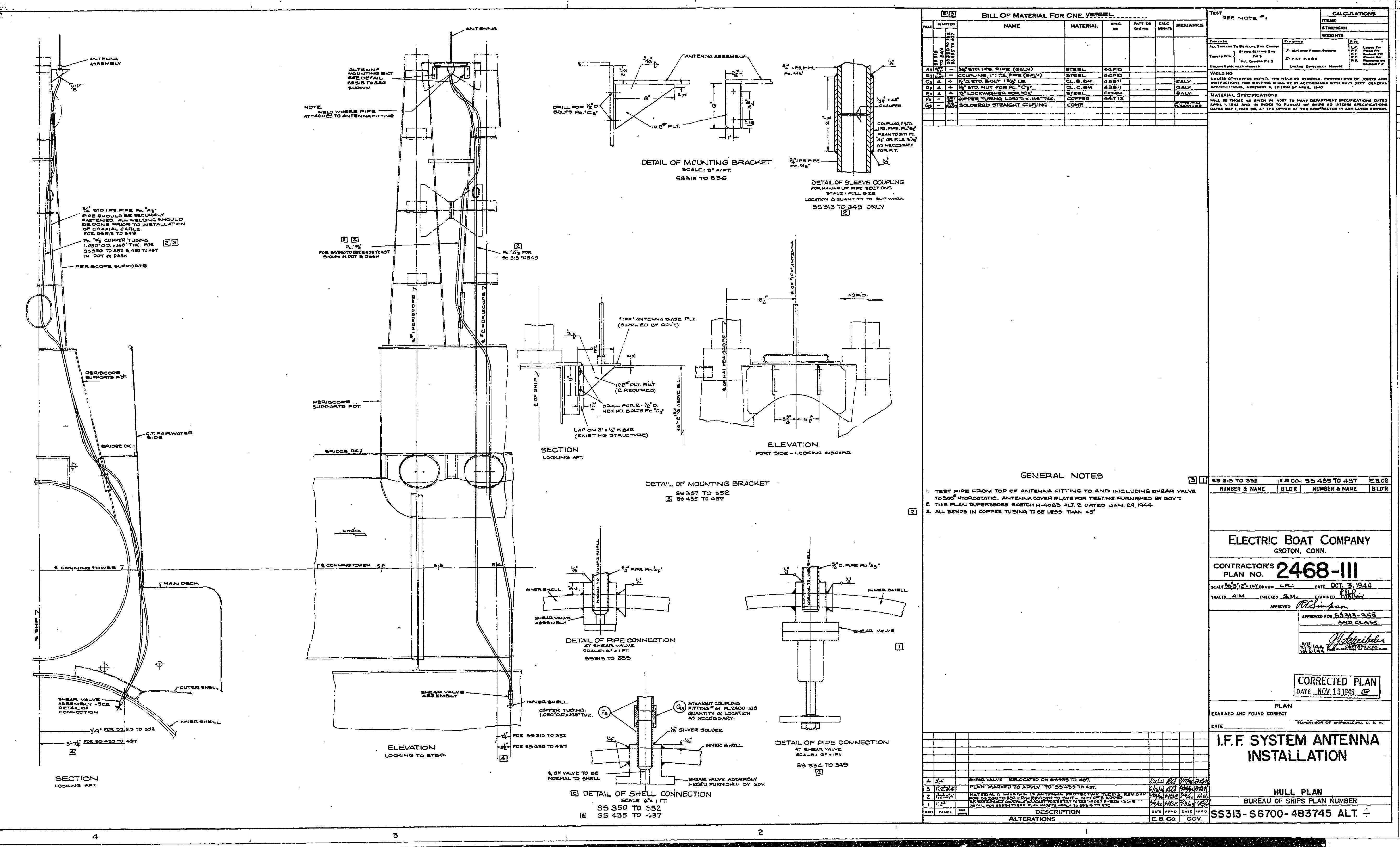
USS Pampanito Identification Friend or Foe (IFF) ReplacementThis note is a description of the project to replace the missing Identification Friend or Foe (IFF) equipment on USS Pampanito. It is also thank you note to the many individuals and corporations that helped make it possible. The IFF equipment was used to help allies identify each other as friendly from farther away than is possible by sight. A general description of the Mark 3 system used during WW II is available at RADAR OPERATORS' MANUAL, RADAR BULLETIN NO. 3. On Pampanito it was implemented with a BN Interrogator, and ABK Transponder with all the ancillary equipment needed to make them work with the radars on the submarine. Research work to identify the missing equipment began in earnest in 1997 and continues to this day. Documents were found in the US National Archives in College Park, Maryland and San Bruno, California. USS Bowfin found some Pampanito documents in their archives. One of the WW II veterans remembered the ABKs location. Manuals where borrowed to copy or bought from private collectors. Photos were taken of other museum submarines. Microfilm was copied, then digitized, then indexed. Key documents were a work order for the removal of the equipment from 1955, generic installation instructions for submarines, Pampanito's submarine characteristics cards from 1944 and the equipment manuals. By the mid 1990s we had a pretty good idea of what equipment was missing and we started searching for it. The largest pieces, the BN and the ABKs were located fairly quickly. However the shock mounts, control boxes, mounting brackets, unusual plugs and jacks took much longer to assemble. Our confidence level about what was missing and where it went grew with each piece of equipment or document acquired. However, we have not found any photos from our target restoration period in this area of the boat. It was not until 2011 that we decided to began mounting the equipment even though we did not have everything needed, and we had still not found any photos. We know that we had two ABK-1s and one BN from the Submarine Characteristics cards, the BN control boxes and cabling left over from removal in 1955, the equipment removal work order from 1955, and war patrol reports. This page is a status report on a work in progress. It will be updated from time to time as equipment is installed, new documents found, etc. All the installed pieces of the IFF system in the control room and conning tower that are not listed below are original and remain in their original locations. They did not do a thorough job of removing everything in 1955. To recap, we have added the following equipment in our best guess as to where they were mounted, no new holes were drilled. Some of the equipment was mounted with hex head bolts that should have round head screws. None of it has been wired in yet. ABKs - Missing paint, and holes in the bulkhead match the pre-drydocking radar foundations in control room drawing found at the National Archives. Ralph W. built the replica foundation to be consistent with other foundations on the boat. Both ABKs and shock mounts are WW II material purchased from private sources. Neither ABK has been restored. Note that ABK-1 and ABK-7 are the same 28VDC models except for the manufacturer. There is a high probability that we placed these in the correct location. BN - The location was chosen because it matched the pre-drydocking radar foundations in control room drawing found at National Archives. We found weldment on the periscope well in the expected locations. The replica foundations that were built by Ralph W. closely match the drawing. The WW II BN has not been restored. There is a high probability that is the right spot based on the drawing and weld marks. However, USS Drum has the BN mounted fore and aft on a foundation that stretches between the periscope wells. Note that everything else is mounted in slightly different locations on Drum even though she had a Mare Island refit about the same time as Pampanito. CTZ-50ACW duplexer. This is a replacement built in WW II and bought from a collector. The holes fit on the gauge board, esp. with the extension plate, and it makes sense that this is close to the BN. We are not sure when the extension plate was installed. The bolts where replaced. There is a high probability it is in the right spot. CAGQ-24 AAL antenna change over switch. This is a replacement. The holes on the gauge board lined up and it makes sense to be next to the duplexer and very close to BN. There is a high probability it is in the right spot. IFF IN USE indicator light - This is the pilot light for the BN. It needs to be close to the radar operator. It makes sense that it be close to the BN remote control. This could also have been on the bulkhead next to the ABKs. The holes lined up nicely on the panel. The indicator light came from SBRF, the lens is a replica created on a laser cutter. Medium probability that it is in the right spot. BK DESTRUCTOR indicator light. This is used to test the BK destruct circuit. It needs to be close to the ABKs. The indicator light came from SBRF, the lens is a replica. The text copied from other museum submarines. Medium probability that it is in the right spot. BK DESTRUCT SWITCH. We have no idea where this was, but it needs to be away from the ABK. We could not find a WW II switch. This one, which is similar, but round faced is from the 1970s off a ship in SBRF. We have photos from Drum and other subs showing the square type that is also in the manuals. The label is replica, the text is copied from other museum submarines. The mounting tabs on the bottom where modified to fit the four hole pattern where we guess the WW II switch was mounted. It makes sense to be farther from the ABK, but in sight. One drawing from before the June 1945 refit showed it on the periscope well. The DANGER text might have been in red (it is on DRUM), but with the red lights used at night we do not think it should be red. ABK Control box and ABK power plug, ABK power cable, BK M/G ON switch. The control box, power plug, cable are all replacements acquired from dealers and collectors. The foundation is replica and speculation in type and location. The mounting bracket for the control box is a close replica. BK power rotary switch is WW II from SBRF, the label is replica. It makes sense for this to be close to the ABK Control Unit. - BK M/G On Indicator light We are not sure Pampanito had an M/G. Our original assumption was it did, now we believe it was powered by a battery tap. Equipment that has been collected, but not yet installed. This is stored in the container: - We have most, but not all of the plugs and jacks, etc. needed to wire the equipment in. See the wish list for the ones that we know are missing. - Spare transponder to use as a spare parts set to restore the two ABKs on the boat. It is stored in the container. - Fuse junction box for BK power. We have a water tight box from an SBRF ship, but the other boats have smaller non-watertight box. This probably mounts between the periscope wells. Missing still, see the wish list: - Relay junction box, or a junction box of the correct size that can be modified into a replica junction box, and of course the relay itself that goes in the box. This probably mounted between the periscope wells on a missing foundation. There are weldments that hint at the location of missing foundations. - MG set for ABK. We now think that she used a battery tap that still exists and runs to the galley instead of an MG set. Originally we thought this might be only for a pre-1945 VHF radio, but that radio was replaced with a 120vac radio in 1945. The running to the galley and stopping is typical of the incomplete 1955 removal of the IFF gear. We have not found a location for an MG set foundation or source of 120vdc power for a MG set. Lastly, we found a USS Becuna drawing that shows ABK power from a battery tap. - The antenna and shear valve are missing. We copied a manual for the antenna from USS Bowfin. We can probably replicate the antenna. We have one each of the VHF antenna and shear valve that can be copied as well. FYI, we are not sure that in 1955 they did not take the VHF antenna and that the one of the boat is actually the IFF antenna. They are the same antenna, close in wavelength and the piping from the shears would indicate that they took the wrong one. - The cable that ran from the junction box between the sonar and radar in the conning tower to a missing junction box in the control room needs to be replaced. The original BN control box and IFF In Use indicator are still mounted and wired in the conning tower. The original BN control box is still located in the control room, but only one of the cables was left in place. - A junction box to match the one in the conning tower for the control room that accepted the multi-conductor cable from the conning tower. This probably mounted on a missing foundation between the periscope wells. We have something that might work, but it is not the same size and type as in the conning tower. - Some of jacks and plugs. See the wish list. - Watertight screw-in stuffing tubes. - BN power switch. We are not sure if we need another rotary switch. There is a switch on the radar indicator, and in the remote unit. This would be the third switch, we need to see what is on some of the other museum submarines. Power probably came from SV radar power junction both below the gauge panel and between the periscopes. If there was a switch it might have been mounted where the BK Destruct switch is currently mounted and the destruct switch on the periscope well. - Inert AN-M3 destructors for the ABKs. It would really help if we could find some historic photos of this area from before 1955. It is hard to express how much we appreciate the advice, help, donations and discounted products and services from individuals and companies along the way. We had the help of an very talented team. We could not have succeeded without the incredible generosity of these people and companies: ADVICE AND HELP:
Volunteers and Staff of USS Pampanito, https://maritime.org/sub DONORS:
Tom Horsfall PROVIDED PRODUCTS AND SERVICES AT DISCOUNT:
Joyce Brothers Metal Works Inc. Rich Pekelney, Pampanito Volunteer was the project manager.
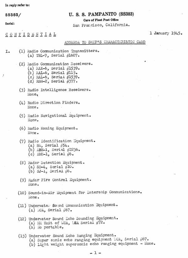
- Pampanito Submarine Characteristics Card, Addenda Jan 1945.
Drawings:
|
