GENERAL
SECTION 1-Preliminary Adjustments
SECTION 2-Leak-Meter Test of Torpedo
SECTION 3-Test and Installation of Exercise Head
SECTION 4-Final Adjustments and Final Preparation for Firing
SECTION 5-Treatment After a Run
SECTION 6-Routine for Upkeep of Fully Ready Torpedo
SECTION 7-Lubrication Guide
SECTION 8-General Information
GENERAL
1. Preliminary Adjustments are made to ascertain that there are no leaks, and that various controlling units will function properly as received from overhaul, also to check coincidence of reference marks together with index dials and pointers for alignment and accuracy. With preliminary adjustments completed, the torpedo is ready for final adjustments.
2. Final Adjustments are made in preparation for a war shot or for an exercise of a torpedo.
3. It will be noted that symbols (capital letters) are used to designate oils, greases, and preservatives having application in various steps of the adjustments. Explanation of these symbols is, given below:
Oildag, Torpedo Stock Part 67165, a 10% suspension of graphite in petroleum oil. Cleaning Solvent, Federal Spec. PS 661, Stock No. 51-C-1326-67 (5 gal.),51-C-1326- 75 (50 gal.)
110
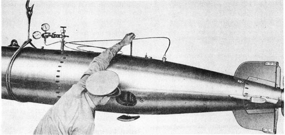
4. Preliminary adjustments should be made with the torpedo resting on a truck or chocks, with the exercise head removed, located under a chain hoist.
5. Equipment, tools, and supplies required for use in making preliminary adjustments:
Equipment required
Torpedo truck or chocks
Hoisting strap (short)
Safety strap.
Test panel, SG 2348, or torpedo-testing set SG 5033
Two propeller locks
Pressure gage (portable)
Oil-filling funnel
Tools required
The tools required are listed after each step.
Supplies required
Lubricant and preservatives listed above.
6. The above material is given in allowance lists for all torpedo activities.
Chapter 7-Section 1
PRELIMINARY ADJUSTMENTS
Charge Air Flask
1. Place torpedo right-side-up on truck or chocks.
2. Put on propeller lock and starting-lever lock.
3. Remove water-compartment filling plug. (11)
4. Remove fuel-filling plug. (217,74)
5. Remove charging valve plug and washer. (13-14)
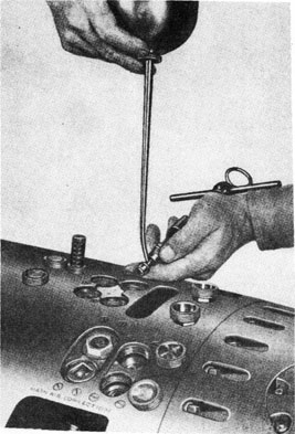
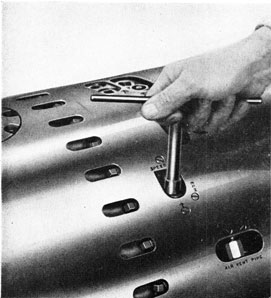
6. Rotate starting-gear index spindle, in the direction of the arrow, to seat starting piston. (227-227A)
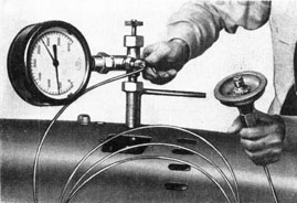
7. Open stop valve (Fig. 102). Make certain that air-flask blow valve is closed. (227-227A,49)
8. Before installing charging line, tie wing nut down and blow air line free of moisture and foreign material.
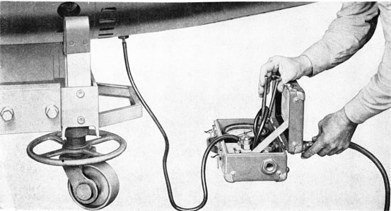
9. Install charging line and safety strap (Fig. 103).
10. Charge air flask to 1000 p.s.i. pressure; if final adjustments are to follow, flask may be charged to 2800 p.s.i. pressure. Charge at a rate not to exceed the full charge in 20 minutes. Charging should be done through air filters when supplied.
11. Close stop valve; bleed air from charging line, remove safety strap and charging line, and replace charging valve plug and washer. (227-227A, 13-14)
12. Test forward bulkhead for leaks, using oil (C).
Drain Air Flask-Forged Flask
13. Turn torpedo until nipple for blow valve is at its lowest point; crack blow valve and drain water from air flask; close blow valve and turn torpedo right-side-up. (49)
Figure 102
111
Figure 103
Drain Air Flask-Welded Flask
14. Turn torpedo bottom-side-up until the air vent in the top forward part of the air flask is at its lowest point; open air vent and drain water from air flask. Close air vent and turn torpedo right-side up. (400B)
Oil and Grease
15. Remove plug and fill oil tanks with oil (B) (preferably warm). After filling, remove propeller lock; turn propellers by hand and note that oil pump takes suction as evidenced by the dropping of oil level in the filling hole. Refill oil tanks and replace plug. (13-14)
Note: When torpedoes have been converted for smokeless running. (NavOrd Ordalt 1654), delete Step 15. The oil tanks are to remain empty until the final adjustments.
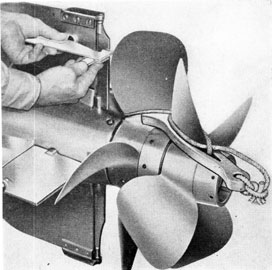
16. Remove after propeller sleeve assembly. Wipe bushings and bearing surfaces clean with rag; rub grease (G) on bushings and bearing surface on sleeve (Fig. 104). (183)
17. Remove grease-packing screw and washer from after propeller shaft. With hand grease gun, fill after propeller shaft with grease (G). Turn propellers at least three turns while greasing. Replace grease packing screw and washer. (184, 481, 481A)
Use (S) when torpedoes have the improved tail lubricating system.
Note: Do not apply an excessive amount of grease, as it will cause torpedo to smoke while running.
18. Replace after propeller sleeve assembly and secure with lock nut. (183)
19. In torpedoes which do not have the improved tail lubricating system, remove grease plug from tail cone, fill tail bearing with grease (G), and
replace grease plug, noting that it is proper plug (flat end). Turn propellers at least three turns while greasing. (13-14, 481, 481B)
Use (S) when torpedoes have the improved tail lubricating system.
Figure 104
112
Figure 105
Figure 106
20. In torpedoes which do not have the improved tail lubricating system, remove grease plug from forward propeller, fill hub with grease (G), and replace grease plug. Turn propellers at least three turns while greasing. Replace propeller lock. (40, 481, 481B)
21. In torpedoes which have the improved tail lubricating system, remove grease plug from after propeller, fill grease shell (inside after propeller sleeve) with grease (S), and replace grease plug. Turn propellers at least three turns while greasing. Replace propeller rock. (40, 481, 481B)
22. Remove drain plugs in the afterbody and tail, and drain out excess oil, if any. Leave plugs out. (13-14)
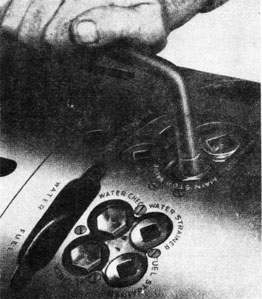
Prepare Check Valves and Strainers
23. Remove plugs and washers from air check valve body and delivery check valve body; exercise and oil (C) check valves; replace plugs washers (Fig. 105). (405, 406, 74)
Note: If valves are sticky, it will be necessary to remove them and correct the trouble (Fig. 106).
113
Figure 107
24. Remove plugs, washers, and fuel and water strainers. Wash strainers and blow dry with air. Note that mesh is clean. Replace strainers, washers, and plugs.
(405, 372A)
Install Control Valve
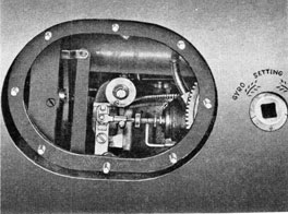
25. Turn torpedo bottom-side-up. Remove hand-hole plates, gaskets, and port forward gyro index-gear assembly. (200-441, 48, 72)
26. Test and set control valve for the pressure indicated in the record book.
27. Install control valve in afterbody and connect pipes (Fig. 107). (41, 155, 141A)
Check and Adjust Depth Mechanism
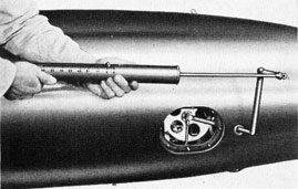
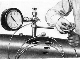
28. Test atmospheric chamber for leaks, using test fixture; SG 2857:
(a) Remove plug from atmospheric chamber and install test connection with gage. (11, 402)
(b) Connect test pump; pump to 15 p.s.i. pressure and check for leaks (Fig. 108).
Note: The atmospheric chamber must hold 15 p.s.i. pressure for five minutes; if it does not, renew diaphragm and repeat test.
(c) Remove test pump and test connection. (402)
(d) Turn torpedo right-side-up.
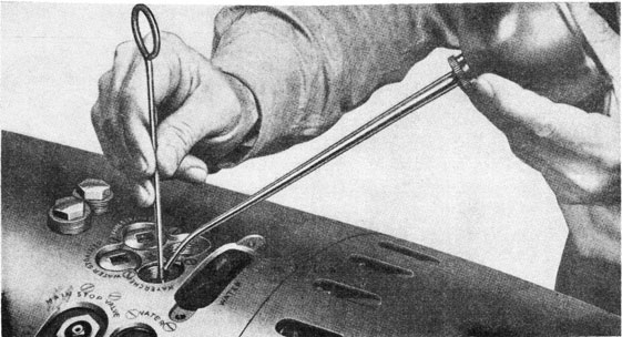
29. Remove plug from air-strainer body and install adapter. (12, 223, 377)
30. Connect air from test panel, SG 2348, or test set, SG 5033, to adapter in air-strainer body. (141A)
Note: Check operation of water lubrication check valve. With the air off, pass a light copper wire through the lower vent hole in the check valve body. With the valve in the closed position the wire should pass just underneath the piston. With the air on and the valve open, the wire should not pass, since the piston will cover both the vent holes.
31. Check alignment of depth rudders with zero lines.
32. With transportation screw in place; turn air on (450 p.s.i.) and note position of depth- engine valve connecting rod with respect to valve stop. Scribe mark on valve connecting rod should be in alignment with scribe mark on valve stop; if not, unclamp and adjust valve to that position.
Note: If valve has been adjusted, make certain that hole in knurled portion of valve connecting rod is horizontal.
33. With transportation screw in place, and air on, check neutral position of depth rudders. The neutral position should be one
Figure 108
114
Figure 109
down. If neutral position is incorrect, loosen clamp screw in rudder-adjusting rod, remove connecting screw and turn rudder-adjusting eye in the direction desired. It will be noted that one-half turn is the minimum amount this eye can be turned for alignment with the forked end of the rudder-rod connection. One-half turn on the eye is equivalent to one-quarter of a graduation on the tail cone. After adjusting the eye, re-connect and clamp adjustment. (49, 386)
34. Remove transportation screw and install replacement screw. (49)
35. With air on, move pendulum by hand both ways against its stops. The full rudder throws should be two up and four down (Fig. 109). If these throws are not obtained, find interference and remedy before proceeding to next step.
36. Install hoisting strap and hoist torpedo clear of truck.
37. Install screw hook in diaphragm nut and attach 10-pound weight. (411A)
38. Place bevel protractor on the top center of air flask (not on guide stud) and level the torpedo.
Figure 110
115
Figure 111
39. By turning the depth index spindle (Fig. 110), apply tension on the depth spring until the scribe mark on the depth-engine valve connecting rod is in alignment with the scribe mark on the valve stop (Fig. 111). Move the pendulum back and forth by hand and note that scribe marks line up when pendulum comes to rest.
40. If the depth-index dial does not read 10 feet when the valve is centered, disengage side gear spindle from socket; set depth index dial on 10 feet and re-engage spindle in socket. (135A, 472)
41. Verify neutral rudder throw with the weight attached and the torpedo level.
42. Test sensitiveness of pendulum by tilting torpedo (Fig. 112). The pendulum should start to move with not more than
one-half degree of tilt up or down, and should have full travel with not more than 2 1/4 degrees of tilt. Use bevel protractor to obtain the correct tilting angles for this test.
43. Remove weight and screw hook from diaphragm nut. (411A)
Figure 113
44. Replace access plug and washer in atmospheric chamber. (11)
45. Set depth-index dial on zero. (135A)
46. Remove replacement screw and replace transportation screw. (49)
47. Lower torpedo on truck.
Figure 112
116
Figure 114
Check Adjustment of Steering Rudders
48. Remove propeller lock and move propellers by hand until pallet is clear of pallet pawls. Replace propeller lock. With air on engine, move the steering-engine valve in both directions by hand, recording the steering rudder throws with vernier scale (Fig. 113). The steering-rudder throws should
be equal in both directions and should agree with throws in record book. (44)
49. Turn off air and remove test pipe. (141A)
50. Remove adapter and replace plug in air-strainer body, noting that washer is in place. (377, 12)
Check Functioning of Gyro and Gyro Mechanism in Torpedo
51. Move speed-change spindle from high to low several times and note ease of
Figure 115
operation. Set spindle to low-speed position. (This step is not applicable to Torpedoes Mk 23 Type (Fig. 114). (419)
Figure 116
117
52. Replace water-compartment filling plug. (11)
53. Replace forward gyro index gear assembly. (444)
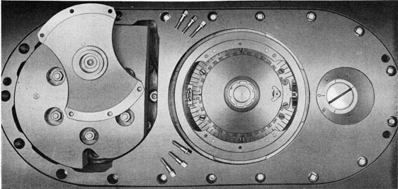
54. Check torque required to turn socket (Fig. 115). The torque should be not more than five foot-pounds. (227-227A, 98)
57. Turn angle-setting device extremely (160 degrees) to the left and right from the outside setting socket to insure that there is no interference. (444)
58. Check coincidence of zero in pot with the outside index (Fig. 116). It is essential that these correspond. (444)
59. Wipe the inside of the gyro pot dry with a clean cloth (without lint).
60. Remove propeller lock and turn propellers by hand to move pallet and cam pawls to extreme after position, away from the gyro (Fig. 116). Replace propeller lock.
61. Inspect and oil [two drops of oil (A) ] gyro top bearing, using syringe furnished.
62. Lock and unlock spinning mechanism by hand and note smartness of action. (205A-246)
63. Inspect and install gyro, taking care not to damage extender in top bearing holder.
64. Inspect and oil [two drops of oil (A)] gyro bottom bearing. Install gyro bottom head with zero marks coinciding. (Note 1). (205A-246)
65. Replace drain plugs and washers in afterbody and tail. (13-14)
66. Turn torpedo right-side-up. (See Note 2, below.)
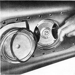
67. Lock and unlock gyro by hand. Note that centering pin releases freely and without a kick (Fig. 117). Grasp outer gimbal ring and, by lifting, note if there is any clearance between top and bottom bearings. If there is no clearance, the gyro may have been installed slightly canted and forced up
Figure 117
against the side of the top bearing when setting up on the bottom head screws.
(205A-246)
Note 1: By spinning the outer gimbal ring of the gyro while the bottom head is being installed, the gyro will align itself in the top and bottom bearings and prevent the condition described above.
Note 2: Turning the torpedo right-side-up to inspect the proper functioning of the centering pin in the spinning mechanism is absolutely necessary to insure the proper release of the gyro from the locked position. Checking the functioning of the centering pin with the torpedo bottom-side-up is incorrect procedure because in this position the gyro is not in proper alignment with the centering pin, and the latter cannot release without kicking the gyro.
68. Lock gyro and turn torpedo bottom-side-up. Check to see that hand trip lever is flush against the recess in the gyro-pot wall. If lever is not flush, gyro is not fully locked; therefore unlock gyro, turn the spinning gear one and one-half turns (clockwise viewed from aft) and lock again. The gyro should now be locked as evidenced by the hand trip lever being flush against the recess in the gyro-pot wall. Replace gyro clamp plate cover and gasket. Turn torpedo right-side-up. (205-246, 13-14)
118
Figure 118
69. Place steering engine valve in the approximate mid-position by hand; remove propeller lock and turn propellers by hand, watching the steering-engine valve meanwhile; if the valve moves, the gyro top plate is not properly indexed for a straight
Figure 119
shot. It should be centered by turning the outside setting socket. After centering, note discrepancies between the reference mark in the pot and the outside setting-socket index; report the discrepancy to the Torpedo Officer. (444)
Test Functionings of Depth and Gyro Mechanism with Gyro
and Main Engine Running
70. Install dummy igniter and connect pipe. (391A, 438)
71. Secure two propeller locks on two opposite propeller blades.
72. Remove transportation screw and insert replacement screw. (49)
73. Hoist torpedo clear of truck.
74. Turn starting-gear index spindle past the "click" to seat starting piston. Keep tool on spindle for emergency use. (227-227A)
75. Remove lock from starting lever.
76. Trip starting lever by hand.
77. Open stop valve smartly, thus spinning gyro. Close stop valve (Fig. 118). (227-227A)
119
78. Remove both propeller locks.
Note: Place a guard around propellers. If no guard is available, caution personnel to stand clear of propellers.
79. Open stop valve sufficiently to run the main engine at moderate speed, and at the same time maintain sufficient pressure to actuate the depth and steering engines. (227-227A)
80. Swing torpedo in azimuth, noting movement of steering rudders to either side. Tilt torpedo up and down (Fig. 119). Depth rudders should move smoothly and get full throw.
81. Rotate starting-gear index spindle to seat starting piston, and note that air is cut off. (227-227A)
82. Close stop valve. (227-227A)
83. Replace one propeller lock and starting-lever lock.
84. Remove replacement screw and install transportation screw. (49)
85. Lower torpedo into truck or chocks and turn bottom-side-up.
86. Permit the gyro to run down by itself.
87. Remove gyro clamp-plate cover and gasket. (13-14)
88. Remove gyro bottom head. (205A-246)
89. Remove gyro; clean thoroughly; oil (A) and replace in gyro container.
90. Replace gyro bottom head.
91. Replace gyro clamp-plate cover and gasket. (13-14)
92. Inspect water intake and discharge scoops for after bulkhead bearing. Note that scoops are free from grease or dirt to permit free circulation. (40)
The above steps will complete the Preliminary Adjustments and place the torpedo in readiness for Final Adjustments preparatory to firing, except for the exercise head, the adjustments of which are described under its own heading.
Chapter 7-Section 2
LEAK-METER TEST OF TORPEDO
Note 1: The submarine torpedo officer should normally test torpedoes received from overhaul with the leak meter (SG 4566), both as a receiving inspection and to determine the length of time each torpedo can be safely exposed to sea pressures at different depths. Normally he will place the tightest torpedoes in those tubes which will be flooded for the longest periods.
Note 2: The vacuum gage of leak meter should not be altered in any way unless it is extremely inaccurate. As a test, the gage is sufficiently accurate if it will register
within an inch or two of 28 inches of vacuum when the set is working properly. In order to prevent damage to gage, always relieve vacuum slowly to allow gage hand to return slowly to its resting point.
1. Make certain that stop valve is closed, starting lever lock is in place, and propeller lock is on. (227-227A)
2. Connect ordinary air hose from 100 to 600 p.s.i. air source to the 1/4-inch female pipe-thread inlet on bottom of leak meter case.
3. Remove afterbody drain plug and
120
Figure 120
screw in fitting furnished with set. Slip end of Koroseal tubing over nipple on fitting. (13-14, 191)
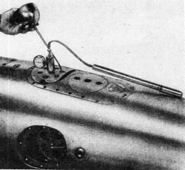
4. Place pinchcock on Koroseal tubing between gage and fitting in afterbody, and turn on air. When gage registers 25 inches of vacuum, indicating that all connections on test set are tight, remove pinchcock.
5. Continue operation of test set until vacuum gage registers 22 to 25 inches of vacuum, and place pinchcock on short length of Koroseal tubing connected to ejector (Fig. 120). Turn off air.
Note: If vacuum will not rise to this range, extremely bad leakage is indicated.
6. Wait five minutes and read vacuum gage, tapping glass of gage with fingers. Wait 15 more minutes and read gage again, tapping glass of gage with fingers. After-body is adequately tight if vacuum falls 1/2- inch or less during this 15-minute period.
7. After test, remove pinchcock (slowly); remove Koroseal tubing from nipple in afterbody fitting; remove fitting and replace drain plug, noting that washer is in place. (191, 13-14)
WHEN PERFORMED. These test shall be performed within 72 hours of firing a torpedo.
Chapter 7-Section 3
TEST AND INSTALLATION OF EXCECISE HEAD
1. Inspect water discharge-valve parts:
(a) Remove holding nuts, spring plate, spring and valve. (48)
(b) Inspect valve seat, leather washer, and spring. Seat must be clean and leather washer must be in good condition. Renew parts as necessary.
(c) Apply grease (E) to leather washer, valve, seat, and studs in flange.
(d) Replace valve, spring, and spring plate. Secure assembly with holding nuts. Tighten nuts evenly. (48)
(e) Check action of valve by pushing open with rod several times. Valve should close by spring action alone.
3. Check to see that all holding nuts for exercise head bulkhead are tight. (48)
4. Connect nipple in bulkhead to source of high-pressure air (General Use Test Panel, SG 2348, or Testing Set, SG 5033. (141A)
5. Hold forward end of air-releasing pipe clear of head; turn on air-line valve to deliver about 600 p.s.i. pressure; and note flow of air through pipe. If it is suspected that restrictions are present in the air-releasing pipe, they must be located and remedied. Turn off air.
6. Blank off forward end of air-releasing pipe. (141A, 18)
7. Fill exercise head with liquid solution, and immerse end of air releasing pipe.
Figure 121
Note: For information on liquid solutions, see OD 3837.
8. Crack air-line valve and gradually build up pressure in air-releasing pipe to 2800 p.s.i. Bubbles will indicate leaks. All leaks must be located and remedied. Turn off air and bleed air line. Remove blank from end of air-releasing pipe and disconnect
test pipe from nipple on exercise-head
bulkhead. (141A, 18)
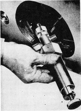
9. Calibrate air-releasing mechanism:
(a) Connect test pipe to air-releasing mechanism. (141A, 18)
(b) Remove keep screw and turn adjusting nut to approximate proper compression on spring (Fig. 121) (41, 18).
Figure 122
(c) Cock mechanism (Mk 2 only; Mk 3 cocks automatically when air is turned on. (200-441)
Caution: When using the cocking tool, be certain to pull tool straight out with respect to mechanism. A side pull may bend the stem and prevent the valve from operating or cause the valve to leak. Hold valve on seat with cocking tool while turning on air.
(d) Turn on air and turn adjusting nut until mechanism blows at 600 p.s.i. (Fig. 122). Turn off air. Replace keep screw. (18, 41)
(e) Connect mechanism to pipe in exercise head. (141A, 18)
(f) Re-connect test pipe to nipple on exercise-head bulkhead. (141A)
10. Cock mechanism (Mk 2 only); open air-line valve to deliver about 1000 p.s.i. pressure; and test air-releasing mechanism and pipe connection for leaks by lowering mechanism into water or solution in head. All leaks must be located and remedied. (200-441)
11. With air still on and mechanism
122
cocked, lower mechanism into flange, noting that a good gasket is in place. Install cover and secure by setting up evenly on nuts. (48)
Note: It is particularly important when preparing exercise heads for firing that the leather gaskets under the air-releasing mechanism, torch case, and torpedo headlight are in good condition, free of hard spots, evenly placed and smoothly spread to make a tight seat. If the seats are not tight, air will leak by these fittings when the air-releasing mechanism blows, the head will be only partially blown, and the torpedo will sink.
12. Check to see that 0.020-inch hole in top of adjusting-nut cap on air-releasing mechanism is clear.
Note: If this hole is clogged and if a small leak by the air-releasing valve develops, the head may be prematurely blown.
13. Install torch case in its flange over a good gasket. If using calcium phosphide torch, visually inspect torch for pin holes around soldered seams. If none are present, drop torch into torch case with ring and tab facing upward. Replace cover and secure with nuts. Tighten nuts evenly. (48)
14. If using headlight, install it as follows:
Note: If headlight or D & R are not used, install gasket, blanking plate, and cover.
(a) Remove casing from headlight and remove small square of fibre from between contact points on switch.
(b) Test switch mechanism by striking the after side of the headlight with the hand to see if lamp lights.
(c) Reset switch to the OFF position by pushing the switch lever with one finger through the elongated slot in the headlight body.
(d) Replace casing on headlight and screw up tight.
(e) Install headlight in its flange over a good gasket; replace cover and secure with nuts. Tighten nuts evenly (48).
Note: Headlight should be located in its flange so that the side of the headlight marked "Tube Aft Firing" is facing aft.
15. Test exercise head for leaks and functioning of its mechanisms:
(a) Place a bucket beneath the water discharge valve to catch discharged water.
(b) Turn off air to air-releasing mechanism; open vent in air line; and allow air to bleed down. Note the pressure at which the head blows. Head should blow at 600 p.s.i.
(c) When head starts to blow, note that water-discharge valve works properly and watch all joints for possible leaks as indicated by spurts of water. Locate and remedy all leaks.
(d) After air line bleeds down to zero, remove test pipe from nipple in bulkhead. (141A)
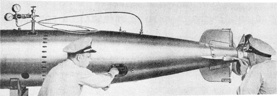
16. Join exercise head to air flask:
(a) Connect air pipe to nipple on air-flask blow valve only. Open air-flask blow valve and note flow of air through pipe. If it is suspected that there is a restriction in the pipe, it must be corrected before proceeding farther. Turn off air-flask blow valve. (404, 49)
(b) Sling exercise head and hoist to level of air flask.
(c) Connect air pipe from air-flask blow valve to nipple on exercise-head bulkhead. (141A)
(d) Cock air-releasing mechanism (Mk 2 only) and open air-flask blow valve. (49)
(e) Test air-pipe connections for leaks, using oil (C). Remedy leaks, if found.
(f) Wipe air flask and head joint with oil (D); join head to flask and secure with joint screws. (49)
Note: When joining head to flask, exercise care not to crush air pipe.
17. Turn torpedo bottom-side-up; remove drain plug; replenish liquid; and replace drain plug, noting that washer is in place. Turn torpedo right-side-up. (13-14)
123
Chapter 7-Section 4
FINAL ADJUSTMENTS AND FINAL PREPARATION FOR FIRING
1. Final adjustments are made in preparation for a run of the torpedo.
2. Equipment, tools, and supplies required for the final adjustments are listed below:
Hoisting strap (short)
Safety strap Propeller lock
Fuel-filling funnel
Oil-filling funnel
Ready tools (numbers of which are listed after
each step) Gyro oil (A)
Hot running torpedo oil (B) (As alternate use (H).)
Light lubricating oil (C)
Compound steam-cylinder oil (D)
Grease (F)
Tail-packing compound (G)
Torpedo tail grease (S)
Oildag (T) Alcohol
Water supply
Tackiwax (L) (if using oil-type exhaust valves)
Brush for tackiwax
For additional information on lubricants, see pages 109 and 135. (13-14)
FINAL ADJUSTMENTS
1. Note that stop valve is closed, starting lever lock is in place, and propeller lock is on. (227-227A)
Oil and Grease
2. Remove plug and fill oil tanks with oil (B) (preferably warm). After filling, remove propeller lock, turn propellers by hand, and note that oil pump takes suction as evidenced by the dropping of oil level in the filling hole. Refill oil tanks and replace plug.
Note: This test does not apply to torpedoes converted for smokeless running (NavOrd Ordalt 1654). (13-14)
3. Remove after propeller-sleeve assembly. Wipe bushings and bearing surfaces clean with rag; rub grease (G) on bushings and bearing surface on sleeve. Use grease (S) when the torpedoes have the improved tail lubricating system. (183)
4. Remove grease-packing screw and washer from after propeller shaft. With hand grease gun, fill after propeller shaft with grease (G). Turn propellers at
least three turns while greasing. Replace grease-packing screw and washer. Use grease (S) when the
torpedoes have the improved tail lubricating system.
(184, 481, 48lA)
Note: Do not apply an excessive amount of grease, as it will cause torpedo to smoke while running.
5. Replace after propeller-sleeve assembly and secure with lock nut. (183)
6. In torpedoes which do not have the improved tail lubricating system, remove grease plug from tail cone, fill tail bearing with grease (G), and replace grease plug, noting that it is proper plug (flat end). Turn propellers at least three turns while greasing. (13-14, 481, 481B)
7. In torpedoes which do not have the improved tail lubricating system, remove grease plug from forward propeller, fill hub with grease (G), and replace grease plug. Turn propellers at least three turns while greasing. Replace propeller lock. (40, 481, 481B)
8. In torpedoes which have the improved tail lubricating system, remove grease plug from after propeller, fill grease shell (inside after propeller sleeve) with grease (S), and replace grease plug. Turn propellers at least three turns while greasing. Replace propeller lock. (40, 481, 481B)
9. Remove drain plugs in the afterbody and tail, and drain out excess oil, if any. Replace plugs. (13-14)
Check Starting Gear.
10. Remove port hand hole-plate and forward gyro index gear assembly.
(48, 200-441, 72)
11. Remove starting-lever lock and rotate starting-gear index spindle one complete turn in the direction indicated by arrow and stop with the index pointer on START. Note that there is enough clearance (0.010 inch) between the piston lever and the starting-piston stem. (227-227A, WE2A)
12. Replace starting-lever lock.
Install Control Valve
13. Test control valve in accordance with
124
instructions given in Chapter 8, and set to pressure as given in record book.
14. Install control valve and secure. (155, 41)
15. Connect air pipe from manifold to control valve. (141A)
Figure 123
16. Connect air pipe from control valve to air-strainer body. (141A)
Charge Air Flask
17. Remove water-compartment filling plug. (11)
18. Remove fuel filling plug. (217, 74)
19. Remove charging valve plug and washer. (13-14)
20. Open stop valve. Make certain that air-flask blow valve is closed. (227-227A, 49)
21. Before installing charging line, tie wing-nut down and blow air line free of moisture and foreign material. Use filters in air lines when supplied.
22. Install charging line and safety strap.
23. Charge air flask to 2800 p.s.i. Charge at a rate not to exceed the full charge in 20 minutes.
24. Close stop valve; bleed air from charging line; remove safety strap and charging line; and replace charging valve plug and washer. (227-227A, 13-14)
25. Crack stop valve one-half turn. (227-227A)
Prepare Check Valves and Strainers
26. Remove plugs and washers from air check - valve body and delivery check-valve
body; exercise and oil (C) check valves; replace plugs and washers. (405, 406, 74)
27. Remove plugs, washers, and fuel and water strainers. Wash strainers and blow dry with air. Note that mesh is clean. Replace strainers, washers, and plugs. (408, 372A)
Speed Setting
28. Set speed-change mechanism. (This step is not applicable to Torpedoes 23 Type.) (419)
Fill Fuel and Water Compartments
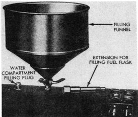
29. Fill fuel flask. Use filling funnel.
30. Replace fuel filling plug. (74, 217)
31. Fill water compartment. Use filling funnel (Fig. 123).
32. Replace water-compartment filling plug, Noting that washer under plug is in place. (11)
Drain Combustion Flask
33. Disconnect pipe and remove dummy igniter. (438, 391A)
34. Turn torpedo to port; drain combustion flask; and turn torpedo bottom-side-up.
Figure 124
Note: Keep finger over end of igniter pipe, while draining combustion flask, to prevent liquid from entering pipe (Fig. 124).
125
Figure 125
Install Gyro
35. Remove gyro clamp-plate cover and gasket. (13-14)
36. Remove gyro bottom head (Fig. 125). (205A-246)
37. Replace forward gyro index gear assembly. (444)
38. Note that gyro top plate is exactly on zero and check with outside side-setting socket, which should also indicate zero.
39. Wipe inside of the gyro pot dry with a clean cloth (without lint).
40. Remove propeller lock and turn propellers by hand to move pallet and cam pawls to extreme after position, away from the gyro. Replace propeller lock.
41. Inspect and oil [two drops of oil (A) ] gyro top bearing, using syringe furnished.
42. Lock and unlock spinning mechanism by hand and note smartness of action. (205A-246)
43. Inspect and install gyro, taking care not to damage extender in top bearing holder.
44. Inspect and oil [two drops of oil (A) ] gyro bottom bearing. Install gyro bottom head with zero marks coinciding. Turn torpedo right-side-up. (205A-246)
Note: It is good practice to cause gyro to revolve on its upper bearing when
installing bottom head, thus making certain that balls and bottom bearing are lined up.
45. Lock and unlock gyro by hand. Note that centering pin releases freely and without a kick (see Note 2 following step 67 of "Preliminary Adjustments.") (205A-246)
46. Turn torpedo bottom-side-up and lock gyro (Fig. 126). Check to see that hand trip lever is flush against the recess in the gyro-pot wall. Again note that gyro top plate is set on zero. (205A-246)
48. Replace gasket and hand-hole plate, setting up evenly on the holding nuts. (48)
49. Check tightness of joint screws in afterbody and tail. (386, 49)
50. Check lock nut for after propeller sleeve. (183)
Prepare Depth Mechanism
51. Remove transportation screw. (49)
52. Insert replacement screw with washer in place. (49)
53. Set depth index. (135A)
FINAL PREPARATION FOR FIRING
54. Install war head:
(a) Remove steel protecting ring. (49)
(b) Clean joint ring and coat with oil (D).
(c) Attach war head to air flask with joint screws. (49)
55. Turn torpedo bottom-side-up.
56. Remove cover from exploder-mechanism casing. (49 or 456)
57. Thoroughly clean and dry exploder-mechanism casing.
58. Note that the impact switch has been previously fitted to the war head and that proper clearance (0.063 inch) between switch contacts has been obtained.
(WE2A)
59. Test Exploder-Mechanism Mk 6-5:
(a) Friction test:
(1) Lift mechanism from box. (MF2)
(2) Grease (F) impeller shaft, using grease gun and adapter.
(MF1, MF1A)
(3) Lay mechanism on its side with pick-up coil down.
(4) Note that arming screw is up and the threads are disengaged from threads on arming gear (armed position).
(5) Remove screws and impeller guard. (41)
(6) Turn impeller (less than a turn) to break adhesion of grease in bearing, and with impeller test tool on tip of one impeller blade, exert enough pressure to just start impeller (Fig. 127). The force required should be 22 to 24 ounces. (MF7)
Note: To obtain proper friction, it may be necessary to adjust the impeller gland nut.
Figure 128
127
(7) Replace impeller guard and holding screws. (41)
(b) Set delay-device worm wheel back to starting position, noting that contact button is against worm wheel and that wire to delay wheel is of sufficient length to permit full engagement of worm wheel and worm. Replace pin in delay-wheel arm and bracket to hold wheel in engaged position (Fig. 128).
Caution: Delay wheel, wire, contact button and insulation bushing should be in perfect condition, free from dirt, oil, grease, or corrosion.
60. Ascertain that core-rod plug is tight. (388)
61. Install Tetryl Booster Mk 2 in casing:
(a) Remove booster from container and replace container in stowage space.
(b) Install booster in casing with recess for detonator out.
(c) Note that booster is a loose fit in the casing, so that it will rest on the safety chamber when torpedo is turned right-side-up.
62. Install Detonator Mk 9:
(a) Loosen set screw and remove idler gear with pin, or disengage spring idler gear, if installed; line up scribe mark on arming screw and turn arming gear with arming screw disengaged from arming gear (in armed position); replace idler gear, pin, and set screw or reengage spring idler gear. (37)
(b) Thread wires from detonator through hole in arming screw.
(c) Install safety chamber and detonator on arming gear, noting that guide pins on arming screw slide into detonator holder. Secure safety chamber with holding screws. (41)
(d) Separate ends of detonator leads and connect them to two terminals on the bakelite strip attached to the firing-mechanism base. These leads may be connected to either post. (435)
(e) After connecting, coat wire ends and terminals with three coats of insulating varnish or shellac.
63. Install exploder mechanism in war head:
(a) Carefully examine gasket; place it in position and install guide screws in the war-head flange to hold gasket in place while guiding exploder to its seat.
(497. 41)
(b) Connect leads from exploder mechanism to impact switch by threading the ends of the leads over the top of
Figure 129
the switch and through the base of the switch, and then secure leads to terminals on bakelite block (Fig. 129). (435)
Note: These leads may be connected to either post.
(c) Coat terminals and exposed wires at terminals with three coats of insulating varnish or shellac. Tie leads between exploder mechanism and impact switch to inboard side of the pick-up coil, near pick-up-coil junction box, with string.
(d) Place cover over impact switch and secure with holding screw. (41)
(e) Screw lifting screws in place from the outside of exploder base, noting that they are not screwed in too far, so the ends will extend above gasket seat, thus damaging gasket when installing exploder. Lift exploder over casing.
(MF2)
128
(f) Install impact switch and bracket assembly in war head.
(g) Carefully slide exploder mechanism into place, noting that it fits snugly on its flange in war head and that no binding exists, such as may occur if the flexible leads are jammed between exploder casing and pick-up coil or any other part of the mechanism and the exploder cavity in war head.
Caution: Extreme care must be taken to see that wires to impact switch are not cut or grounded when installing exploder in head; otherwise exploder will not function.
64. Set up evenly on base-plate holding; crews and remove lifting screws.
(49, MF2)
Note: Care should be taken to set up evenly on all holding screws.
65. Leakage test (Fig. 130):
(a) Remove plug in base plate and install adapter set to open at five p.s.i. (39, MF15)
(b) Pump five p.s.i. air pressure into exploder casing and inspect for leaks around base plate, impeller shaft, plug in A.C.M. piston hole, and 'plug for core rod with soapy water.
(c) Remove test set and replace plug.
(MF15, 39)
66. Turn torpedo right side-up.
(a) With torpedoes converted for smokeless running (NavOrd Ordalt 1654), fill the oil tanks with 25 pints of clear, fresh water (distilled, if available).
67. Remove starting lever lock and load torpedo in tube carefully. Do not jam against stop.
68. Note that tube tripping latch works freely and is in proper position. Close tube door.
69. Check buffer clearance ( readjust as necessary).
70. Engage gyro angle-setting spindles.
71. Set gyro to an arbitrary angle (preferably 45 degrees or over) in either direction, making note of same.
72. Engage depth-setting spindle and set an arbitrary depth on torpedo, making note of same.
73. Disengage tube-setting spindles.
74. Haul torpedo out to afterbody joint ring, or as necessary to complete final preparation for firing.
75. Remove gyro clamp-plate cover and note angle on gyro index in the pot. This angle should correspond to the angle setting on tube. (13-14)
76. Reset gyro index in pot to zero, noting that side setting sockets on both sides read zero. (444)
77. Reset gyro angle-setting mechanism on tube on zero.
78. Replace gyro clamp-plate cover and gasket. (13-14)
79. Note reading on depth-index dial. It should correspond with reading on tube.
Figure 130
129
Figure 131
80. Again rotate starting index spindle one complete turn in the direction indicated by arrow on dial to seat starting piston. Match pointers on index spindle and starting gear. (227-227A)
82. Remove tail. (See Note.) For procedure see Chapter 8.
Note: Execution of steps 84 to 87 inclusive is not required on torpedoes fitted with new-type exhaust valves.
83. Wipe and clean oil from around exhaust-valve seats.
84. Heat Tackiwax to approximately 215 degrees and apply with a brush around exhaust valve seats. One application is sufficient.
85. Replace tail. For procedure see Chapter 8.
Caution: Under no circumstances should the tail be allowed to rest on or touch holding studs for exhaust-valve bracket when reassembling on afterbody, as this may jar the exhaust-valve bracket sufficiently to break the seal of the Tackiwax. Extreme care should be exercised that no change in rudder-rod adjustments takes place after removal of tail.
86. Open stop valve wide and turn back one-eighth turn. (227-227A)
87. Install igniter with washer, and connect pipe. (391A, 438)
Note: When connecting the igniter, be sure that nut is set up tight.
88. Run torpedo home gently until guide stud meets stop bolt.
89. Engage depth and gyro spindles with tube-setting gears and check for engagement.
90. Remove depth setting as set in step 74.
Caution: Be absolutely certain at all times when torpedo is loaded in tube that the gyro angle setting and depth setting on torpedo and the tube are in coincidence.
91. Place propellers in a position for easy removal of propeller lock.
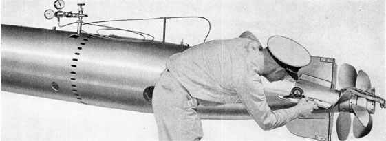
92. Remove grease plug and washer from propeller shaft and repack propeller shafts with grease (G) (Fig. 131). Use grease (S) when torpedoes have the improved tail lubricating system.
(184, 481, 48lA)
Note: Do not turn propellers after repacking shafts.
93. Replace grease plug and washer. (184)
94. Remove propeller lock.
95. Check buffer clearance, being careful not to force torpedo guide stud under stop bolt.
96. Re-check check-off list carefully W make certain that no step was omitted. Close tube door.
The above will complete the final adjustments and final preparation for firing.
130
Chapter 7-Section 5
TREATMENT AFTER A RUN.
The following procedure should be carried out immediately after firing, to prevent deterioration of material.
Immediately Upon Retrieving
1. Close stop valve. (227-227A)
2. Put on propeller lock.
After Hoisting on Board
3. Place torpedo on truck or chocks; close air flask blow valve; and install starting-lever lock. (49)
4. Rotate starting-gear index spindle to seat starting piston. (227-227A)
5. Remove headlight from exercise head and re-set switch. (48)
Drain Afterbody and Tail
6. Remove replacement screw and insert transportation screw. (49)
7. Remove drain plugs from afterbody and tail. (13-14)
8. Replace afterbody drain plug. (13-14)
9. Remove gyro clamp-plate cover. (13-14)
10. Disconnect pipe and remove igniter. (39lA, 438),
Fill Oil Tanks
11. Fill oil tanks with oil (B). Measure quantity of oil required to fill tanks and note difference between this amount and the capacity of oil tanks to determine quantity used during run.
Note: If torpedo has been converted for smokeless running (NavOrd Ordalt 1654) and is to be fired without overhaul as a conventional shot, drain oil tanks of water before adding oil. If torpedo has been fired as a smokeless shot and is to be overhauled prior to firing again, the afterbody must be thoroughly slushed with rust-preventive (J) immediately upon recovery. The torpedo will be given a blow-down run for two or three minutes with (J) in the oil tanks to clear moisture from the ball bearings. Unless the torpedo is to be disassembled immediately (within six to eight hours after recovery), neglect of this treatment may result in serious rusting of the balls, races, and other bearing surfaces, which will necessitate replacement of the parts effected. (13-14)
Drain Combustion Flask
12. Turn torpedo over sufficiently to drain combustion flask.
42. Clean, inspect, grease (G) bushings thoroughly, and replace on after propeller sleeve. Use grease (S) when torpedoes have the improved tail lubricating system.
43. Replace after propeller sleeve and propeller.
44. Replace after propeller-sleeve locknut. (183)
45. Replace rudder connection screws. (386)
46. Replace rudder access and tail drain plugs. (13-14)
47. Remove grease-packing screw and washer from after propeller shaft. With hand grease gun, fill after propeller shaft with grease (G). Turn propellers at least three turns while greasing. Replace grease-packing screw and washer. Use grease (S) when torpedoes have improved tail lubricating system. (184,481,48lA)
48. In torpedoes which do not have the improved tail lubricating system, remove grease plug from tail cone, fill tail bearing with grease (G), and replace grease plug, noting that it is proper plug (flat end). Turn propellers at least three turns while greasing. (13-14,481,48lB)
49. In torpedoes which do not have the improved tail lubricating system, remove grease plug from forward propeller, fill hub with grease (G), and replace grease plug. Turn propellers at least three turns while greasing. Replace propeller lock. (40,481,481B)
50. In torpedoes which have the improved tail lubricating system, 'remove grease plug from after propeller, fill grease shell (inside after propeller sleeve) with grease
(S) and replace grease plug. Turn propellers at least three turns while greasing. Replace propeller lock. (40, 481, 481B)
Make Deck Run to Check and Oil Engine
51. Remove charging-valve plug, and install charging pipe and safety strap. (13-14)
52. Open stop valve and charge flask to 1000 p.s.i. (227-227A)
53. Close stop valve. (227-227A)
54. Bleed and remove charging pipe and safety strap.
55. Replace charging-valve plug. (13-14)
56. Place tool on starting-gear spindle as a safety measure. (227-227A)
57. Remove propeller lock.
58. Set speed-change mechanism to low speed (not applicable to Torpedoes Mk 23 Type. (419)
59. Turn propellers by hand and note if engine turns over freely.
60. Remove starting-lever lock and push starting lever to the rear.
61. Gradually open stop valve and give torpedo a deck run until clean oil comes out of drain plug. Control speed with stop valve. (227-227A)
62. Rotate starting-index spindle to seat
starting piston. (227-227A)
63. Close stop valve. (227-227A)
64. Replace propeller lock and starting-lever lock.
79. Install lifting screws and remove gyro and depth mechanism from afterbody. (200-441)
80. Wipe gyro pot dry, using rags free of lint.
81. Blow moisture out of gyro top bearing with low-pressure air. Oil (A) two drops, using syringe.
82. Blow moisture out of gyro bottom bearing with low-pressure air. Oil (A) two drops, using syringe.
83. Blow moisture out of spinning mechanism with low-pressure air. Wipe all parts dry and apply oil (B).
84. Wipe dry all parts of gyro and depth mechanism. Oil (B) thoroughly for preservation.
Oil Engine Gearing and Bearings
85. Remove manifold cover plate.
(48, 200-441)
86. Remove main engine; thoroughly slush all parts. Oil (B) and replace.
Note: If conditions prevent the removal of main engine for preservation, immediately after firing, the procedure outlined below may be carried out as a temporary expedient. It must be understood, however, that the only effective method for preserving the power plant during the interval between firing and complete overhaul by the tender is by its removal from the afterbody in order to slush properly all parts.
Temporary Procedure: With heated oil (B), use oil syringe and lubricate and spray all parts of main engine, starting gear, etc., paying particular attention to ball races, washers, and steel parts, which would become rusty from lack of attention. This can be accomplished through the hand holes, the manifold access hole, and the gyro housing opening. (94)
Starting Gear
87. Blow moisture out of the starting gear with low-pressure air, noting that the mechanism is free of rust and in proper working order. Oil (B), using oil syringe. (94)
Replace Gyro and Depth Mechanism
88. Replace gyro and depth mechanism
with gasket, and secure. (200-441, 456)
89. Connect gyro spin pipe. (437)
90. Replace depth and steering engines. Make valve and rudder-rod connections. (49A, 205A-246)
91. Connect air pipes to steering engine. (24, 141A)
92. Connect air pipe to depth engine. (141A)
93. Connect water pipe to depth-mechanism casing. (144)
94. Replace gyro bottom head.
(205A-246)
95. Replace gyro clamp-plate cover and gasket. (13-14)
96. Drain afterbody and tail, and replace plugs. (13-14)
The above steps will place the torpedo in a state of preservation until opportunity is given for overhaul by the tender.
133
Chapter 7-Section 6
ROUTINE FOR UPKEEP OF FULLY READY TORPEDO
DAILY
If tubes have not been flooded:
1. Disengage tube spindles; open tube door; install propeller lock (do not turn propellers) and withdraw torpedo sufficiently for access to stop and charging valve.
2. Install starting-lever lock.
3. Gage air flask. Boost if necessary. (13-14)
4. Remove starting-lever lock and push torpedo back into tube.
5. Remove propeller lock.
6. Close tube door.
7. Engage tube spindles.
If tubes have been flooded:
1. Disengage tube spindles; open tube door; install propeller lock; and withdraw torpedo sufficiently for access to stop and charging valve.
5. Lubricate tail as in steps 3 through 5of "Final Adjustments."
6. Remove starting lever lock and push torpedo back into tube.
7. Remove propeller lock.
8. Repack tail bearing with grease (G). (Do not turn propellers after re-packing.) Use grease (S) when torpedoes have the improved tail lubricating system. (183,40,481,48lA,481B)
9. Close tube door.
10. Engage tube spindles.
WEEKLY
Proceed as in step under "If tubes have been flooded," with the following additions:
1. Turn propellers by hand at least 100 turns. Turn propellers l0 times only if NavOrd Ordalt 1654 has been accomplished.
2. Shift speed-change mechanism to both speeds and return to required speed setting (not applicable to Torpedoes Mk 23 Type). (419)
3. Operate depth-setting mechanism from zero to 50 feet and return to zero. (135A)
4. Refill oil tanks. NOTE: When torpedoes have been converted for smokeless running (NavOrd Ord-alt 1654), fill oil tanks with clear, fresh water (distilled, if available). (13-14)
MONTHLY, OR AFTER EACH
SEA PATROL
1. Remove torpedo from tube:
(a) Open tube door and put on propeller lock.
(b) Lift tripping latch.
(c) Disengage tube spindles.
(d) Remove torpedo from tube and place on skid.
(e) Close stop valve. (227-227A)
2. Install starting-lever lock.
3. Disconnect and remove igniter. Note condition of end seal. Replace in container and put in stowage space. (438, 391A)
4. Remove afterbody drain plug and one tail-cone drain plug. Drain afterbody and tail cone. Replace drain plugs. (13-14)
5. Turn torpedo bottom-side-up, draining combustion flask on way over.
6. Remove exploder mechanism, detonator, impact switch, and booster:
(a) Remove screw; filler piece, plug and washer, and felt washer from recess in nose of head. (40, 388)
(b) Remove pick-up coil core and disassemble. (MF5)
(c) Replace plug and washer, filler piece, and screw. (388, 40)
(d) Remove holding screws from exploder-mechanism base plate. (49)
(e) Install lifting tools and lift mechanism sufficiently clear to disconnect wires to impact switch. (MF2)
(f) Disconnect wires from switch. (435)
(g) Remove mechanism to bench.
(h) Remove screws, safety chamber, and detonator. Replace screws in exploder mechanism. (41)
(i) Place detonator in container; seal up tightly and place in stowage space.
(j) Install lifting tools on the inside of the base plate and place mechanism
134
in box. Place impact switch in box.
Secure box and place in stowage space.
(MF2)
7. Remove booster from casing; place in container, seal tightly, and place in stowage space.
8. Replace cover plate in exploder mechanism casing in head and secure. (49)
9. Turn torpedo right-side-up.
10. Remove check valve plugs, work and oil (C) check valves, and replace plugs. (405, 406, 74)
11. Remove strainer plugs; remove and clean fuel and water strainers. Replace strainers and strainer plugs. (405, 372A)
12. Remove hand-hole plates and port forward gyro index gear assembly. (48, 72)
13. Check action of starting gear:
(a) Remove starting-lever lock and throw starting lever to rear by hand.
(b) Rotate starting gear index spindle through several complete revolutions. Continue until scribe marks coincide.
(227-227A)
14. Test setting of control valve:
(a) Break connections and remove control valve. (141A, 41, 155)
(b) Test control valve in Control Valve Testing Panel and note that pressure is same as record-book pressure. Note that control valve functions properly. For procedure, see Chapter 8.
(c) Install control valve in afterbody and connect pipes. (41, 155, 141A)
15. Operate depth - setting mechanism from zero to 50 feet and return to zero. (135A)
16. Swing pendulum back and forth a few times by hand.
17. Work depth rudders a few times up and down by hand, using one hand on each rudder, with the same amount of force on each.
18. Operate steering rudders by hand, using same method as in step 17.
19. Remove propeller lock. Turn propellers by hand at least 100 turns. Listen for unusual sounds. Check action of pallet and slide to see that pallet does not engage pallet
pawls while in neutral position with gyro locked.
Note: When torpedoes have been converted for smokeless running (NavOrd Ordalt 1654), turn the propellers only a sufficient number of turns to accomplish the purposes of the 3rd and 4th sentences of this paragraph.
20. While propellers are being turned over by hand, move steering-engine control valve by hand. Note that pallet does not strike pallet pawls.
21. Try speed-change mechanism in both speeds; re-set for desired speed setting-(not applicable to Torpedoes Mk 23 Type). (419)
22. Replace propeller lock.
23. Lubricate torpedo:
(a) Remove plug and fill oil tanks with oil (B) (preferably warm). After filling, remove propeller lock; turn propellers by hand and note that oil pump takes suction as evidenced by the dropping of oil level in the filling hole. Refill oil tanks and replace plug.
Note: When torpedoes have been converted for smokeless running, (NavOrd Ordalt 1654), fill the oil tanks with clear, fresh water (distilled, if available. (13-14)
(b) Remove grease-packing screw and washer from after propeller shaft. With hand grease gun, fill after propeller shaft with grease (G). Turn propellers at least three turns while greasing. Replace grease-packing screw and washer. Use grease (S) when the torpedoes have the improved tail lubricating system. (184, 481, 481A)
(c) In torpedoes which do not have the improved tail lubricating system, remove grease plug from tail cone, fill tail bearing with grease (G), and replace grease plug, noting that it is proper plug (flat end). Turn propellers at least three turns while greasing. (13-14, 481, 481B)
(d) In torpedoes which do not have the improved tail lubricating system, remove grease plug from forward propeller, fill hub with grease (G), and replace grease plug. Turn propellers at least three turns while greasing. Replace propeller lock. (40, 481, 48lB)
(e) In torpedoes which have the improved tail lubricating system, remove grease plug from after propeller, fill grease shell (inside after propeller sleeve) with grease (S), and replace grease plug. Turn propellers at least three turns while greasing. Replace propeller lock.
(40, 481, 481B)
24. Install starting-lever lock and crack stop valve. (227-227A)
25. Turn torpedo bottom - side - up draining combustion flask on way over.
135
26. Inspect gyro and gyro mechanism:
(a) Remove gyro clamp-plate cover, unlock gyro by hand, and remove bottom head. (13-14, 205A-246)
(b) Remove and inspect gyro, noting that balance nut is tight. Apply two
drops of oil (A) in each bearing, using
syringe.
(c) Lock and unlock spinning mechanism by hand and by rotating spinning shaft. (205A-246)
(d) Turn top plate full range right and left. Note that gyro index inside the pot is on zero and lines up with outside setting. (444)
(e) Remove propeller lock and turn propellers until cam pawls are in extreme after position. Replace propeller lock.
25. Main Engine Gears and Bearings. Apply petrolatum (E) to balls and races. Apply oil (B) to gears. NOTE: Brush with (T) when torpedoes have been converted for smokeless running (NavOrd Ord-alt 1654).
26. Depth-Index Setting. Apply oil (B).
27. Oil Tanks. Fill with oil (B). NOTE: When torpedoes have been converted for smokeless running, (NavOrd Ordalt 1654), fill with clear, fresh water (distilled, if available).
28. Gyro Reducer. Apply oil (C).
29. Starting Gear. Apply oil (C).
30. Afterbody After-Bulkhead Bearing. Apply
petrolatum (E) at assembly.
31. Exhaust Valves. Apply oil (B).
137
32. Turbine Bulkhead Gasket. Apply oil (D).
33. Oil Pump. Apply oil (B). NOTE. When torpedoes have been converted for smokeless running, (NavOrd Ordalt 1654), apply oil (T) to the gears of the oil pump.
34. Drain Plug. Apply oil (D).
35. Manifold Cover Gasket. Apply oil (D).
36. Gyro Door Frame. Apply oil (D).
37. Depth Mechanism. Apply oil (C).
38. Gyro Mechanism. Lubricate entire mechanism with oil (C).
39. Control Valve. Apply oil (D) to spring, oil (C) to valve.
40. Gyro Spinning and Unlocking Mechanism. Apply oil (C).
41. Depth Engine. Apply oil (C). Immerse packing for engine cylinder in oil (D).
42. Steering Engine. Apply oil (C). Immerse packing for engine cylinder in oil (D).
43. Gyro Bearings. Apply oil (A).
44. Gyro Index Gears. Apply oil (C).
45. Interior of Afterbody. Apply oil (B)after retrieving and pending overhaul.
46. Afterbody and Tail Joint and Joint Screws. Apply oil (D).
47. Rudder-Rod Connections. Apply oil (C). Apply oil (D) to packing in stuffing boxes.
48. Propeller-Shaft Bearings and After Bulkhead Bearing. Grease with packing compound (G). Use grease (S) when the torpedoes have the improved tail lubricating system.
Tail
49. Propeller, Rudder and Tail Blade Surfaces. Coat with rust-preventive compound (K).
50. Rudder Bearings. Apply oil (D).
51. Bearing in Tail Cone. Fill with packing compound (G) (if torpedo does not have improved tail lubricating system). Use grease (S) when the torpedoes have the improved tail lubricating system.
52. Forward Propeller Hub (After Propeller Hub if torpedo has improved tail lubricating system). Fill with packing compound (G). Use grease (S) when the torpedoes have the improved tail lubricating system.
Procedure After a Run
Perform numbers.
1, 27, 31, 39, 43, 45, 48, 51, 52.
Overhaul
Perform all except number 45.
138
Chapter 7-Section 8
GENERAL INFORMATION
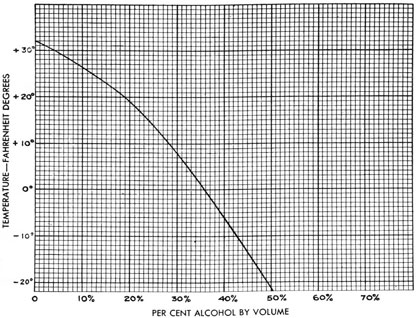
1. Submarines or surface craft which operate in freezing weather, should protect both the water compartment and the exercise head against freezing by the
addition of alcohol to the water when necessary (see Fig. 132B).
2. Possibility of freezing also makes additional precautions necessary to guard against the presence of water in any of the torpedo piping.
3. The method described below should be strictly adhered to for mixing anti-freeze solution:
(a) Alcohol and water should be thoroughly mixed before pouring into the water compartment.
(b) Whenever practicable, the percentage of alcohol in the water compartment should not exceed that necessary to protect against freezing at a temperature of
30 degrees below the existing atmospheric temperature; otherwise power-plant damage may result from the resulting excessive combustion-flask temperature.
Instructions for Mixing Pour-Point Depressant with Hot Running Torpedo Oil for Torpedoes
(Santopour, Monsanto Chemical Co.)
1. If torpedoes are to be used at temperature lower than 40 degrees Fahrenheit, a pour-point depressant compound should be added to the hot running torpedo oil in the oil tank to prevent the oil from congealing at low temperatures. Six ounces of pour-point depressant should be used for each five gallons of hot running torpedo oil. The hot running torpedo oil must be heated to between 140-150 degrees Fahrenheit, the pour-point depressant added, and the mixture agitated until thorough blending is assured.