The afterbody has been called the "torpedo's engine room and brain." In this section of the torpedo are mounted the propelling and controlling mechanisms, the mechanisms which start the torpedo, generate and apply the power necessary to drive it from the time it is launched until it reaches its target, also the mechanisms which determine the torpedo's vertical and horizontal courses and maintain it on those courses so that it will hold true to the mark.
In this chapter, the fittings of, and the mechanisms contained in, the afterbody are described, with the exception of the gyro and depth mechanisms, details of which are given in Chapter 6.
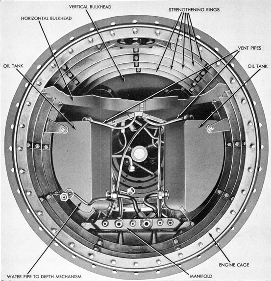
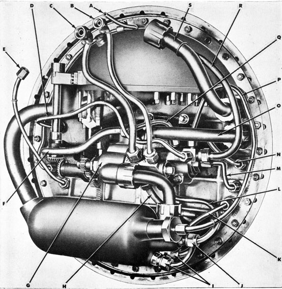
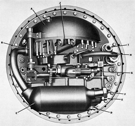
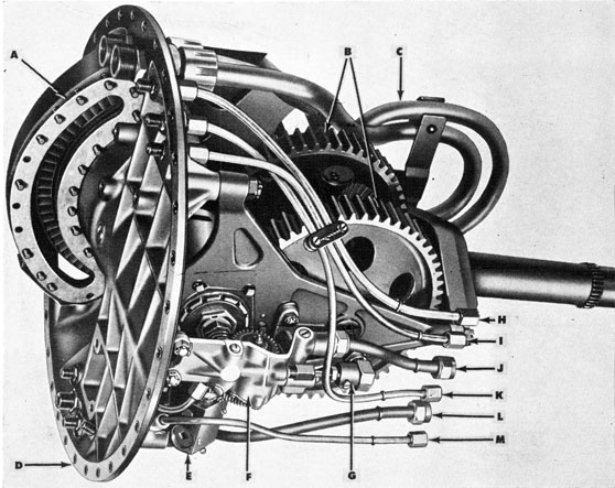
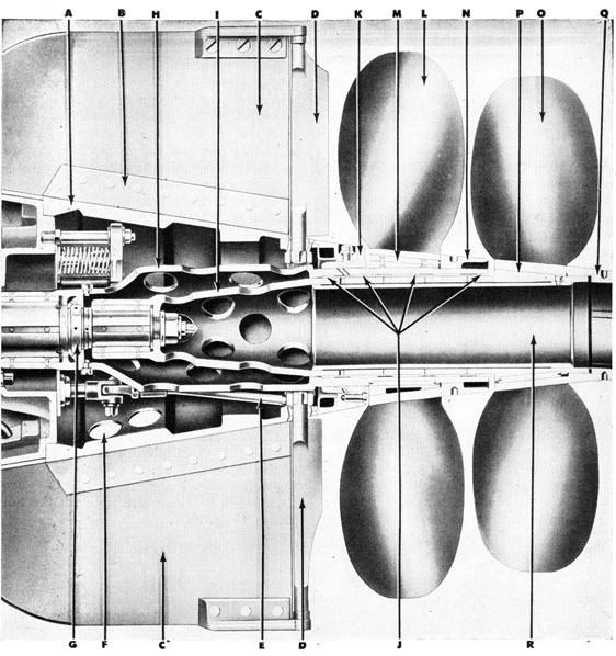
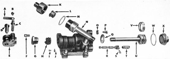
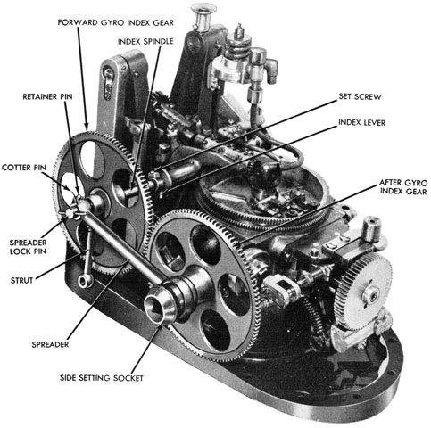
The large cut-away view, Fig. 32 (see foldout), shows these mechanisms in their positions in the afterbody. This illustration should be referred to for locating the individual mechanisms and fittings as they are described in the following pages.
General Construction
The afterbody shell is made of sheet steel, constructed as shown in Fig. 33. To the forward end of the afterbody shell is riveted and soldered the engine cage (see Fig. 33), this being a ring of forged steel which, in addition to reinforcing the end, forms a joint for attaching to the air flask section of the torpedo, and also provides a seat for the turbine bulkhead. The seat for the joint between the air-flask section and the afterbody is slightly tapered in form to facilitate assembly, and also to insure a tight fit and proper alignment. The afterbody is joined to the air flask section
by steel joint screws; the turbine bulkhead is secured to the engine cage by studs and nuts, a gasket being interposed to give a water-tight joint.
The main engine is secured to the turbine bulkhead, and is removed from the afterbody with it as a unit. The engine mechanism is the major component of the propelling mechanism, and is the means by which the energy of the superheated gases delivered by the nozzles is converted into motive power for propelling the torpedo.
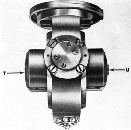
The after end of the afterbody shell is closed by the after bulkhead, which is a bronze casting held to the shell by screw rivets and by soldering. The after-bulkhead bearing, with gasket, U-Seal and retainer, is secured by screws to the after end of the after bulkhead. This bearing supports the after ends of the propeller shafts. The bulkhead bearing is water-cooled during the run, an annular cavity being provided. The cavity is connected by pipes to small scoops on the exterior of the shell, the top scoop pointing forward and the bottom scoop pointing aft. A forced circulation of water results from the motion of the torpedo. (Fig. 64A). Four spring-loaded exhaust valves are secured to the after end of the after bulkhead by means of a valve bracket and studs. These valves permit the escape of gases from the afterbody through the propeller sleeves during a run, and prevent entry of water into the afterbody at the end of the run. Two stuffing boxes in the after bulkhead provide watertight bearings for the depth and steering rudder connections.
42
Figure 33-Interior of Afterbody Shell
Major Mechanisms of the Afterbody
The mechanisms contained in the after-body, or attached to the turbine bulkhead, each of which will be described in detail in this chapter, include the following: The starting gear; the starting and reducing valve group (including the control valve); the super-heating system, which includes the combustion flask, the fuel and water
sprays, and the igniter; the propelling mechanism, which includes the nozzles, the turbine bulkhead, the main engine, the oiling system; exhaust system, and the propeller shafts, sleeves, and hubs, and the propellers. The sleeves, hubs and propellers are described in Chapter 5. The after-body also contains the depth mechanism and the gyro mechanism, which are described in Chapter 6.
43
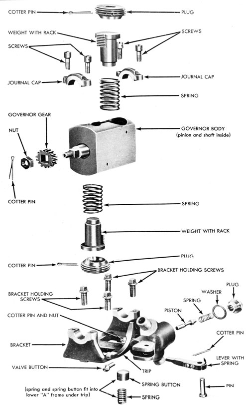
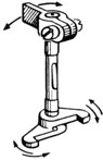
Starting Gear
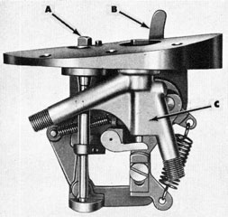
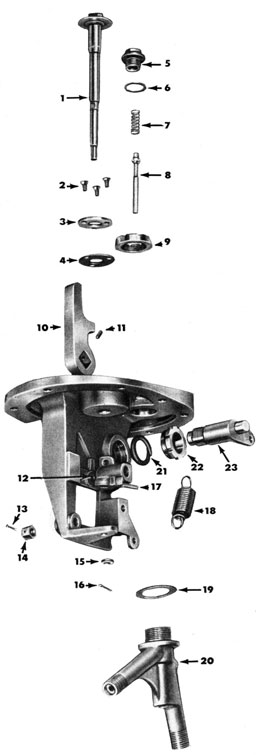
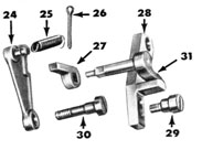
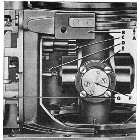
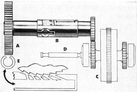
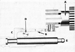
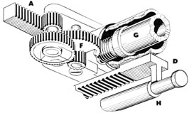
The starting gear (Figs. 34 and 35) is located to the right of the top center line of the afterbody, as shown in Fig. 32. The piston (Fig. 36A) of the starting valve provides the means by which high-pressure air holding the starting valve closed may be exhausted, thus permitting the starting valve to open and start the torpedo (see Fig. 36B). A hand-operated device (Fig. 37), operated from the top of the starting gear, is provided for seating the piston, thus stopping the torpedo during test runs or if accidentally started.
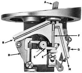
Figs. 36A and 36B are views of the starting-gear body cut away from the valve body to show the operation of the valve, also the air passages.
When the torpedo is launched, the starting lever is thrown to the rear by the torpedo-tube tripping latch. The starting lever is normally held in its forward position by the trip cam spring. In this position the piston lifter is at its lowest position, the starting piston is closed, and the escape of air from above the starting valve is prevented. When the starting lever is forced back by the tripping latch, the action of the trip cam raises the piston lifter. This lifts the starting piston off its seat, thereby allowing the air above the starting valve to escape, permitting the starting valve to open and start the torpedo. At the same time, the catch on the piston lever will move downward, allowing the unlocking lever to move forward, in which position it locks the piston lever, thus holding the starting piston off its seat.
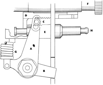
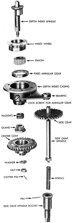
A method is provided for stopping the torpedo after a test run, and for resetting the starting piston before charging the air flask. This consists of an unlocking cam, which is mounted on the index spindle in such a position that, when the index spindle is rotated, the unlocking cam will engage the unlocking lever and force it back. This allows the piston lever and catch to return to their closed positions, and allows the starting piston to seat under the action of air pressure aided by the spring, or of the
spring alone, thus seating the starting valve (in the starting- and reducing-valve body) and shutting off the air supply. The upper end of the index spindle is provided with a flange and has a small head squared to receive a setting tool by means of which it may be rotated. The body is stamped with an arrow showing the direction of rotation.
Figure 34-The Starting Gear, assembled-(A) Index spindle; (B) Starting lever; (C) Starting piston body
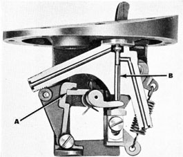
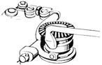
Governor
The function of the governor is to stop a torpedo when it develops excessive speed, and thereby safeguard personnel and prevent serious damage to the torpedo. This is accomplished by centrifugal force actuating the governor, which in turn closes a valve (governor valve) in the air line from the starting piston to the reduced side of the reducing valve, thus banking the air over the main starting valve. By seating, this valve stops the torpedo.
The governor is mounted in a bracket, which is secured to the lower turbine "A" frame, adjacent to the oil pump, and is driven by a pinion on the oil-pump shaft in mesh with a gear on the governor. (See Fig. 38.)
The governor operates as follows: If the speed of the turbines remains within fixed limits, the weights are held in place by the springs (see Fig. 39), but beyond a certain
speed, the pull of centrifugal force in the weights overcomes the spring pressure and the weights fly outward. One of the weights, striking the governor trip (see Fig. 39), will release the governor lever, allowing the governor valve to seat, stopping the torpedo.
While only one plunger strikes the governor trip, two are provided directly opposite each other, the centrifugal forces of both being balanced through their racks and pinion, thus preventing excessive vibration.
The governor trip pivots on a stud in the governor-valve body. Its inboard end is notched, and holds the governor lever in place. The other end curves downward, and is in position to be struck by a governor weight. When struck, it rotates slightly, allowing the governor lever to swing inboard, which in turn allows the valve to seat. The trip is held in position by a spring-loaded button inserted in the lower turbine "A" frame (see Fig. 39).
The governor lever is pivoted in the governor-valve body; it spans the stem of the governor valve, holding it off its seat, and is held by a notch on the governor trip. It tends to swing inboard, by the action of a flat spring screwed to it and bent
around its pivot, when released by the governor trip.
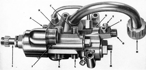
Starting and Reducing Valve Group
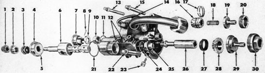
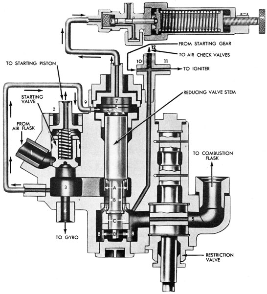
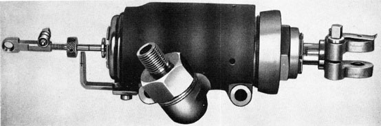
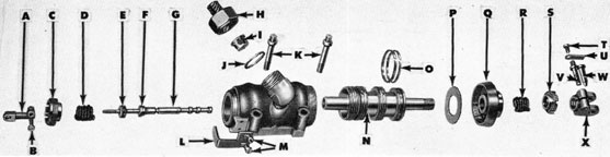
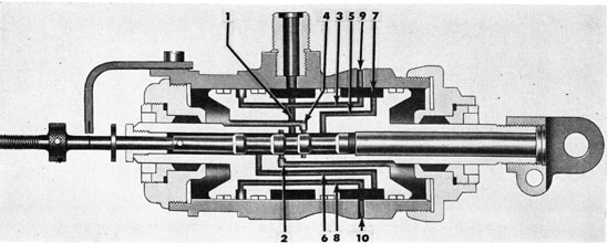
The starting valve, the reducing valve, and the restriction valve are contained in a single body. The body is attached to the turbine bulkhead, as shown in Figs. 40A and 40B, where it forms part of the reducing and superheating system. The complete valve body is shown in Fig. 41A, the parts disassembled in Fig. 41B. Fig. 42 is a diagrammatic drawing showing the operation of the valves.
The starting valve of the torpedo executes a function similar to that of a throttle valve on a steam engine. It opens automatically when the starting gear is tripped. Its essential function is to isolate the stored energy (compressed air) of the torpedo until the proper time for its release, and
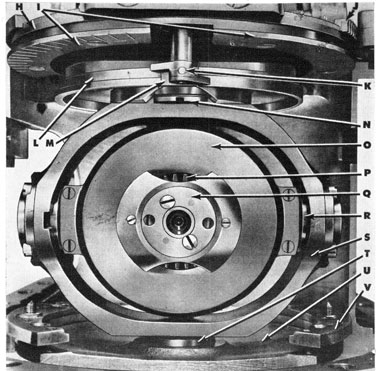
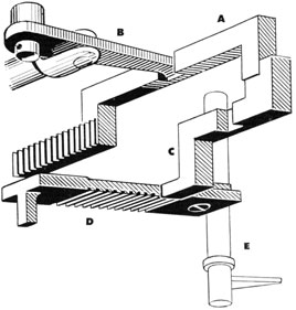
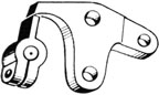
Figure 37-The Starting Gear, top view-(A) Starting lever (starts torpedo automatically when thrown aft); (B) Index spindle (stops torpedo by hand); (C) Plug for starting piston body
then to open automatically when the starting piston is lifted.
Referring to Fig. 42, the operation of starting and reducing valves is as follows: Opening the stop valve, as described in the preceding chapter, allows high-pressure air to pass through (1) to the starting valve,
46
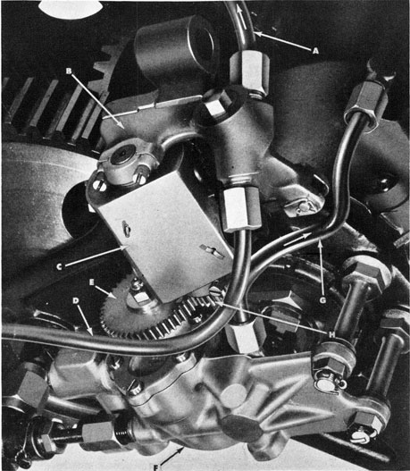
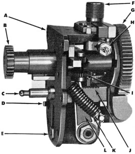
Figure 38-Governor Assembled on Main Engine-(A) Air to reducer; (B) Governor bracket; (C) Governor; (D) Air from starting gear; (E) Governor gear control pump; (F) Oil pump; (G) Oil to spindle casing; (H) Gear on governor
which is held against its seat by a spring and the air pressure above the valve. A small hole or by-pass is drilled through the valve, which allows high-pressure air to enter the space above the valve and bank up in the pipe connected to nipple (2) to the starting gear, where it holds the starting piston on its seat.
When the starting gear is tripped as the torpedo is launched, the high-pressure air is exhausted through (2) from above the
starting valve, allowing the valve to lift against the pressure of the starting-valve spring, thereby allowing the high-pressure air to pass into (3). The air, after passing through the starting gear, returns to the low-pressure side of the reducing valve through (10).
From (3), the high-pressure air leads in three directions: (a) through (4) to the gyro spinning mechanism to give the gyro its initial spin; (b) through the reducing
47
Figure 39-The Governor, showing parts disassembled
48
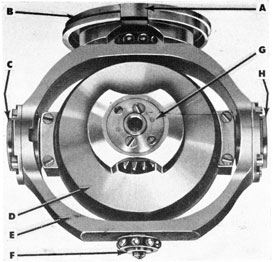
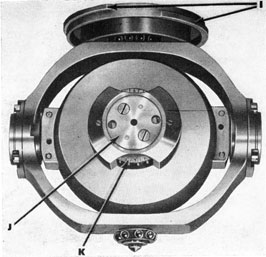
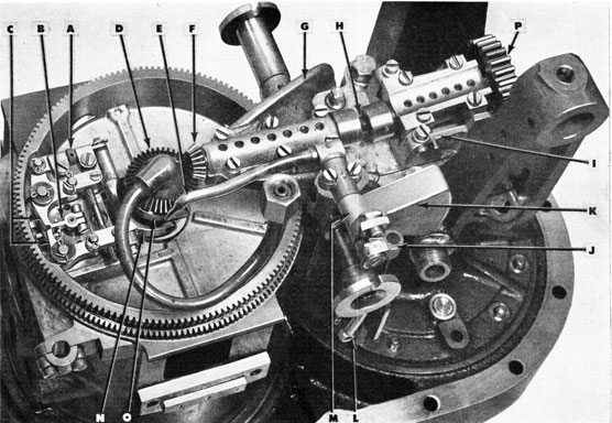
Figure 40A-The Turbine Bulkhead, with attached parts and pipe connections
A-Water pipe to depth mechanism casing B-Fuel pipe (fuel check to restriction valve) C-Water pipe (water check to restriction valve) D-Air pipe (starting gear return) E-Vent pipe F-Air pipe (starting valve to gyro spin) G-Starting and reducing valve group H-Water pipe (restriction valve to water sprays) I -Water sprays
J-Fuel spray K-Air pipe (combustion flask to air-strainer body) L-Fuel pipe (restriction valve to fuel spray) M-Air pipe (reducer to control valve) N-Air pipe (starting valve to starting gear) O-Main air pipe (preheater to starting valve) P-Air pipe (reducer to igniter) Q-Control pipe on reducer R-Air pipe (reducer to air check valves) S-Main air pipe (stop- and charging-valve body to preheater)
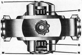
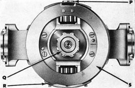
49
Figure 40B-The Turbine Bulkhead, with attached parts
F-Igniter G-Starting and reducing valve group H-Air from preheater coil I-Air to preheater coil J-Nozzle unit
valve to the restriction (5) in the restriction valve and thence to the combustion flask; and (c) from the starting valve chamber (3) through pipe (6) to the control chamber (7).
All pressures acting upward, as indicated
by arrows in areas A-B and D on Fig. 42,
tend to force the reducing valve upward
against its seat, thus decreasing the flow of air passing through. All pressures acting downward, as indicated by arrows in areas E and C-B, tend to open the valve, thus increasing the flow of air passing through. It is therefore evident that the effective pressure area for opening the valve is in the control chamber on the upper end of the
50
Figure 41A-Starting and Reducing Valve Group, assembled-(A) Nipple for gyro spin; (B) Nipple for water-inlet pipe; (C) Nipple for fuel-inlet pipe; (D) Nipple for pipe to starting gear; (E) Nipple for pipe to igniter; (F) Nipple for starting-gear return pipe; (G) Nipple for air checks; (H) Main air-connection nut; (I) Restriction valve stem; (J) Nipple for air pipe to combustion flask; (K) Nipple for water-outlet pipe; (L) Nipple tor fuel-outlet pipe; (M) Nipple tor pipe to control valve.
stem, as shown at E; and the effective pressure areas for closing the valve are in the high-pressure chamber, on the stem area, as shown at A-B, and in the reduced pressure chamber on the area shown at D.
The pressure in the control chamber is adjustable within certain limits by the control valve, which, in effect, is a controlled leak-off
automatically maintaining a constant predetermined pressure in the control chamber. The action of this pressure on the end of the reducing-valve stem, as shown at E, regulates the opening of the reducing valve, and consequently the pressure in the reducing-valve chamber, before passing through the restriction valve.
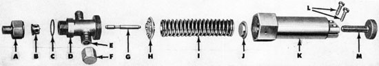
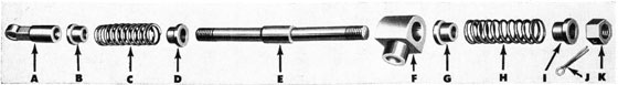
Figure 41D-The Control Valve, disassembled-(A) Cap; (B) Strainer; (C) Washer; (D) Body; (E) Test nipple; (F) Blank nut (washer inside); (G) Control valve; (H) Large spring button; (I) Spring; (J) Small spring button; (K) Spring case; (L) Clamp lock screws; (M) Adjusting screw
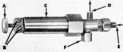
Figure 41C-The Control Valve, assembled (connects to reducing valve)-(A) Adjusting screw; (B) Clamp lock screws; (C) Spring case; (D) Leak-off air to strainer body; (E) Air from control chamber; (F) Blank nut, for testing only
Considering the effect of the pressures in the control chamber, as indicated at E, and in the high-pressure chamber as indicated at A-B, augmented by pressure in the reduced-pressure chamber, as indicated at D, it will be seen that the pressure acting at E will open the reducing valve to a point where the effect of the pressures at A-B and D is sufficient to overcome the effect of the pressure at E. Thus, in order to balance the pressures against area E and areas A-B and D, the reducing valve stem is always seeking to locate itself in a position which will maintain the reduced pressure for which adjusted. Any increase or decrease from the designated pressure in the reduced-pressure chamber will result in the closing or opening, respectively, of the valve, thereby causing a decrease or increase in pressure until the proper value is reached.
The delivery pressure of the reducing valve is the direct function of the pressure which the control valve is set to maintain in the control chamber. An increase in control-valve pressure setting causes increased
reducer delivery pressure; and a decrease in control-valve pressure setting causes a decrease in reducer delivery pressure.
Reduced air also passes through (11) (Fig. 42) to the igniter in the combustion flask, and through (12) to the air checks.
Control Valve
As previously stated, the control valve (shown in Figs. 41C, 41D, and 42) is, in effect, a spring-regulated leak-off for the high-pressure air passing through the
restriction (9) into the control chamber (7) of the reducing valve. The operation is as follows: Opening of the starting valve passes high-pressure air through the restriction (9) to the control chamber (7), gradually building up the pressure in this chamber and unseating the reducing valve. The control chamber and control valve being directly connected, the same pressure is built up in each at the same time.
As the pressure builds up in front of the control valve, it gradually compresses the control-valve spring until, at the determined pressure, the spring is compressed enough to cause the control valve to uncover the groove in the control-valve body, allowing the air to bleed out and pass through the leak-off connection to the air strainer in the afterbody. Thus the control valve, balanced by the spring on one end and the pressure from the control chamber on the other, maintains the pressure constant within very close limits.
In order to control the rate of flow of reduced air, fuel, and water to the combustion
52
Figure 42-Starting and Reducing Valve Group (including Control Valve), diagrammatic view
flask, and thereby regulate the volume of combustion to the requirements of two or five nozzle jets, two sets of restrictions, one set for high speed and one set for low speed, of the required sizes are placed between (a) the reducing valve and the superheater for air, (b) between the fuel check valve and the spray for fuel, and (c) between the
water check valve and the sprays for water. These restrictions are arranged in a rotary valve (see Fig. 42) in such a manner that by rotating the valve 120 degrees a change in restrictions will be affected. The method of operating this valve to change the restrictions will be described under "Speed Change Mechanism".
53
Figure 43-Combustion Flask and Nozzle Unit
Superheating System
The superheating system of the torpedo includes all those parts connected with creating and conveying the energy required to propel the torpedo. These are the combustion flask, the fuel and water sprays, and the igniter.
If used simply as stored, the compressed air in the air flask of the torpedo contains only a definite and limited amount of energy which, with the most economical conversion into motive power, will propel a torpedo for a limited maximum distance at a certain speed. This energy, however, is materially increased during its conversion into motive power by a simple application of the law of expansion of gases on increase of temperature;
and such an increase of temperature is accomplished in the present torpedo design by the superheating system.
In order to grasp clearly the functions of the superheating system, two features incident to torpedo design should be considered: First, that increase of range involves decrease of speed, and therefore decrease of engine working pressure, and vice versa; second, that for any given speed, with the accompanying maximum range at such speed, there is a definite economical engine working pressure.
It is, therefore, apparent that the maintenance of constant and economical working pressure during a run is mandatory to torpedo efficiency. With the reducing and superheating system such as is now being
54
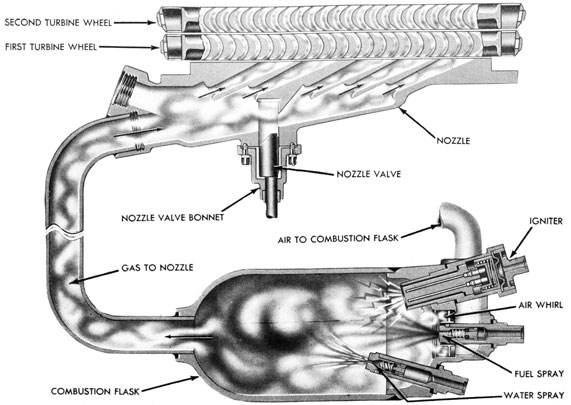
Figure 44-Combustion Flask and Nozzle Unit, diagrammatic view
installed, the variation in pressure during a run is negligible.
Combustion Flask
The function of the combustion flask is to generate gases and steam of proper volume and temperature to drive the main engine, and hence the torpedo, at a specified speed.
Located on the forward side of the turbine bulkhead, as shown in Fig. 40B, is a pressure-tight chamber, the combustion flask, wherein fuel (alcohol) and water are vaporized, mixed with air, and ignited. Once fired by the igniter, the mixture reaches a temperature of approximately 1500 degrees Fahrenheit almost instantaneously, delivering a gas and steam mixture at a working pressure of approximately 450 p.s.i. at high power and 480 p.s.i. at low
power to the nozzles.
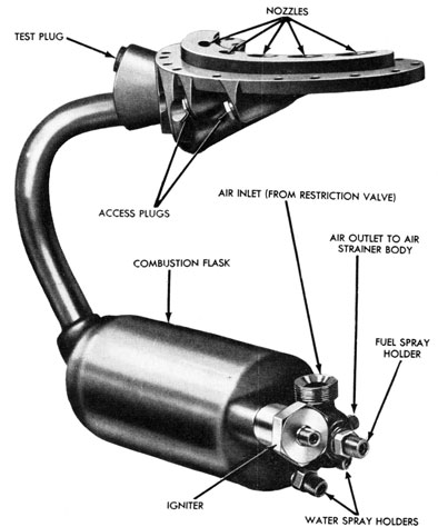
The combustion flask and nozzle unit,
with the air whirl, the igniter, and the fuel and water sprays, is shown in Fig. 43. Fig. 44 is a diagrammatic drawing showing the generation of gases in the combustion flask and their passage through the nozzles and turbines. In Figs. 45A and 45B, the fuel spray and water spray are shown disassembled. These views should be referred to in connection with the following description of the combustion flask.
After passing through the reducing valve and the restriction, as previously described, the air passes through an air whirl and into the combustion flask (see Fig. 44). The air whirl serves to give the air from the restriction valve a whirling motion as it passes through. A hole is drilled and tapped in the center of the cover over the air whirl, this hole being for the fuel-spray holder, the lower end of which is located in the center of the air whirl, being thus positioned for the efficient vaporization of the fuel for
Figure 458-Water Spray, disassembled (parts same as Fig. 45A)
combustion. The water sprays, fuel spray, and igniter are located as shown in Fig. 43.
In order for fuel and water to enter the combustion flask, the pressure of air from the reducer which enters the combustion flask must be less than the pressure of air from the restriction valve which forces the fuel and water into the combustion flask.
The restriction effects the necessary difference in pressures. Low-pressure air from the restriction valve, by passing through the restriction, is reduced by about 25 p.s.i. in high power and 55 p.s.i. in low power before it enters the combustion flask. It is this differential pressure which forces the fuel and water into the combustion flask. In other words, the low-pressure air from the reducer, and behind the fuel and water, has a pressure about 25 to 55 p.s.i. greater than the low-pressure air from the restriction valve which enters the combustion flask.
At almost the instant of firing, air, fuel, and water enter the combustion flask in the order named. When the torpedo is fired, low-pressure air goes to the igniter; the igniter fires and ignites the combustible mixture of air and alcohol. The water prevents injury to the combustion flask by reducing the temperature of the mixture. Since the water, upon absorption of heat, turns to steam, the volume of gases going to the turbines is substantially increased.
A pipe from a nipple on the top of the
combustion flask to the air-strainer body supplies low-pressure air to the depth and steering engines and the gyro reducer.
Fuel and Water Sprays
One fuel and two water sprays deliver fuel and water into the combustion flask in the form of a fine spray or mist. The sprays are similar in construction, as shown in the views of the parts disassembled, Figs. 45A and 45B; also Fig. 44. The holder for the water spray is longer than the holder for the fuel spray.
The fuel spray is calibrated to deliver the proper rate of flow for rapid and efficient combustion, and the water sprays are calibrated to deliver the proper rate of flow for rapid and efficient cooling and subsequent formation of steam. The sprays are calibrated for rate of flow, and not for size of opening.
Igniter
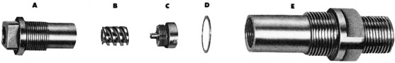
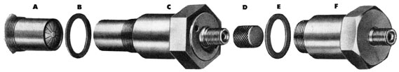
The igniter, which is installed in the combustion flask, is a combined pistol and double fuze, fired by low-pressure air from the reducing valve. The double charge blows out the breakaway head at the lower end of the igniter, (A) in Fig. 46A.
As the torpedo is launched, reduced-pressure air from the reducing valve passes to
56
Figure 46A-Igniter, disassembled-(A) Lower end of igniter; (B) Washer; (C) Igniter assembled; (D) Cap, or protecting nut; (E) Washer; (F) Dummy igniter
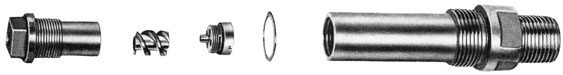
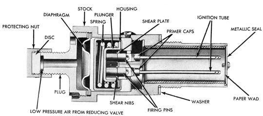
Figure 46B-Igniter, cutaway view
the igniter. The air fires the igniter, which burns long enough to ignite the combustible mixture of air and alcohol in the combustion flask.
The igniter operates as follows: The shear nibs hold the piston and firing pins away from the caps until air pressure of about 250 p.s.i. is built up above the diaphragm, when, by suddenly yielding, the piston assembly and firing pins are forced down on the caps. The firing-pin nibs rest on a small steel shear plate, with holes of lesser diameter than the holes in the igniter tube; this is to insure that the sheared areas are not dragged along on their way down to the firing caps.
Igniters must not be shipped or stowed with torpedoes; hence a dummy igniter is used to replace the regular igniter under these circumstances. When the igniter is not fitted in the combustion flask, it must carry a cap, shown at (D) in Fig. 46A.
Propelling Mechanism
From the combustion flask, hot gases flow through the nozzles (see Fig. 44) to drive the turbines which supply the power for propelling the torpedo. The propelling mechanism includes the main engine, shown in Figs. 49A and 49B, the propellers, and the propeller sleeves and hubs. Various other units are essential to the operation of
the propelling mechanism. These will be described, with the propelling mechanism, in the following paragraphs.
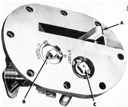
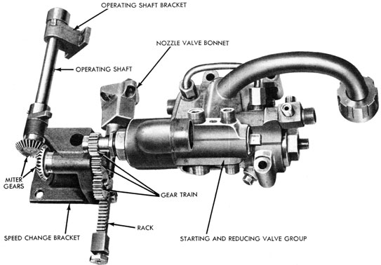
Speed-Change Mechanisms Nozzle and Nozzle Valve
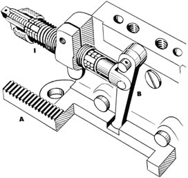
The speed-change mechanism (Fig. 47; also see Figs. 40A and 40B) changes the restrictions in the air, fuel, and water delivery lines, and operates the nozzle valve, changing nozzles from high to low power, or vice versa. This is accomplished by a
system of gears, mounted in a bracket on the turbine bulkhead, and manually operated by a shaft accessible from the outside of the torpedo.
To permit separation of the afterbody from the air flask, the operating shaft is made in two sections, known as the upper operating shaft and the operating shaft. The upper operating shaft is mounted in a bracket attached to the midship section, and has a socket for insertion of the setting tool. This socket is marked with the high-and low-speed setting on its upper end. It is designed to receive the setting tool in only one position, to enable the operator to verify the speed setting from the outside of the launching tube. The tool is turned clockwise for high speed, and counter-clockwise for low speed. Upon removal of the tool, a locking plunger will enter the tool recess and prevent further turning of the shaft.
58
Figure 49A-Main Engine, three-quarter bottom view from port-(A) Turbine pocket; (B) Main driving gears; (C) Preheater coil; (D) Turbine bulkhead; (E) Governor; (F) Oil pump; (G) Oil pump to crosshead; (H) Air to starting gear; (I) Air to air strainer body; (J) Oil suction pipe; (K) Air to control valve; (L) Air to gyro spin; (M) Air return from starting gear to governor
The operating shaft engages with the upper operating shaft, and is supported in brackets on the turbine bulkhead, its lower end being fitted with a miter gear which, in mesh with a similar gear attached to the shaft in the speed-change bracket, operates the gear train to open or close the nozzle valve and rotate the restriction valve to change the restriction.
Inserting the tool will push the locking plunger clear of the slot in the upper operating shaft. By turning the operating shaft clockwise until it stops, motion is imparted through the miter gears to the driving gear, and through the driving gear to a gear on the restriction-valve stem, turning the high
speed restrictions into line. At the same time, motion imparted through the idler gear to the rack on the nozzle valve stem will open the nozzle valve. Turning the operating shaft counter-clockwise to its stop will change the speed setting to low speed.
The nozzle forging and the combustion flask in reality form a unit permanently connected to each other by a pipe. The nozzle unit is a steel forging which fits the opening on the horizontal projection of the upper portion of the turbine bulkhead, as shown in Fig. 49A.
The hot gases are conveyed through the nozzles, impinging upon the turbine buckets of the main engine by means of nozzle jets
59
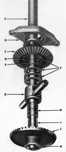
Figure 49B-Main Engine, side view from port-(A) Main driving gears; (B) Forward bevel gear; (C) Bevel pinion; (D) Crosshead; (E) Upper "A" frame; (F) Strut; (G) After bevel gear; (H) Lower "A" frame; (I) Spindle casing
(as shown in Fig. 44), two nozzle jets being utilized for low speed, and five for high speed. These nozzle jets are conical in shape, the smallest diameter being at the throat, the nozzle entrance being.slightly rounded at its entering edge to provide easy approach for the gases. The diameter of the throat fixes the rate of flow of the gases at any given pressure, and is accordingly determined by the power requirements of the torpedo. From the throat the nozzle flares in a conical form, the amount of taper being fixed by the ratio of expansion desired.
The nozzles are placed so as to direct the gases to the turbine buckets. In passing through the conical portion of the nozzles, the gases expand from nozzle pressure to approximately afterbody pressure, and emerge from the mouth at high velocity (about 4000 feet per second).
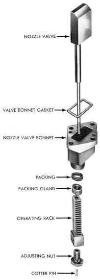
In making the shift from one power to
another, in the Torpedo Mk 14-3A, it is necessary to change the number of nozzles in use. In this torpedo, two nozzles are used in a low-power run, and three more are added for a high-power run. To accomplish this change, a valve (nozzle valve) (see Fig. 48) is installed in the nozzle forging between the second and third nozzles. This valve is carried loosely on a valve stem to permit its seating on a lapped face in the nozzle slot, under nozzle pressure. The valve bonnet, which is bolted to the nozzle forging, covers the valve and its slot, and also provides a bearing for the valve stem on which is mounted the rack for engaging the gearing of the speed-change mechanism.
Turbine Bulkhead
The forward end of the afterbody is closed by a bronze casting, known as the turbine bulkhead, shown in Figs. 49A and 49B, also in Figs. 40A and 40B.
60
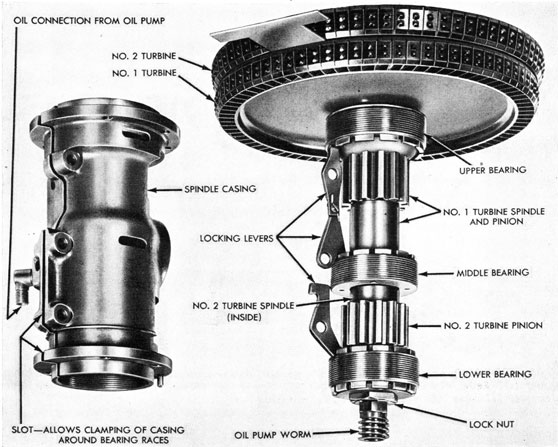
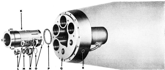
Figure 50-Spindle Casing and Bearings
The upper portion of the bulkhead projects forward, forming the turbine pocket, which has on its lower horizontal surface an opening for attaching the nozzle unit. The engine frames are bolted to this bulkhead on its after face, and thus it supports the entire engine assembly. Also, at its forward side it supports the nozzle unit, the combustion flask, and the starting, reducing, and restriction valve body, and the speed-change mechanism. Suitable nipples are mounted in the bulkhead for connecting the air-pipe lines that pass through the bulkhead, including the preheater pipe which is supported in a bracket extending from the upper "A" frame.
Main Engine
The main engine is of the turbine-driven,
gear-reduction type. It is frequently spoken of as a balanced turbine engine, due to the fact that the turbines and gearing are in pairs, revolving in opposite directions, thus neutralizing the gyroscopic effect of the rotation of the turbines on the torpedo. The engine consists essentially of two turbine rotors, each mounted on a suitable spindle, one within the other, and a system of gearing for conveying the drive to the propeller shafts. Ball bearings are used wherever space permits.
The main engine is mounted in a frame supported on the turbine bulkhead. This frame is assembled in three sections, the upper and lower engine frames ("A" frames), and the engine-frame strut. The forward ends of the "A" frames are secured to the turbine bulkhead, and the after ends
61
are cross connected by the engine-frame strut, thus forming the engine frame. Mounted vertically in the center line of the forward portion of the engine frame is the turbine-spindle casing, and similarly mounted mid-way between the spindle casing and the strut is the crosshead. A top bearing holder mounted over the upper "A" frame completes the engine frame and fixed supports for the main engine bearing.
The turbine wheels are manufactured of alloy steel. The blades project radially
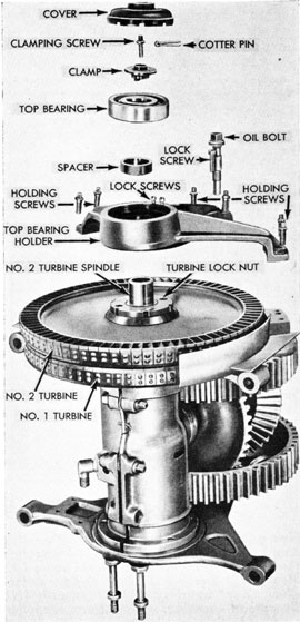
Figure 51-Top Bearing, disassembled
from the periphery of the wheel, and are of practically crescent-shaped sections. Projections are machined on the end of each blade to form rivets for the turbine band. The turbine band is made up of individual segments, each overlapping the other, with sufficient clearance on the butt ends to allow for expansion; each segment is riveted to its blade. The second turbine wheel has slightly larger blades of the opposite curvature from the first turbine to expand the gases further after passing through the first turbine, and thus maintain the velocity until expanded through both turbines. Tapered holes and keyways in the center of the turbine wheels permit assembling to the turbine spindles.
The turbine spindles are mounted in the spindle casing, which, in turn, is bolted to the upper and lower engine "A" frames. The crosshead supports the main driving gears and bevel pinions, and is bolted to the engine "A" frames.
The turbine spindles are supported both radially and axially by four ball bearings. Three of the bearings are in the spindle casing (see Fig. 50), and the fourth is located above the spindle casing in the top bearing holder (see Fig. 51), which is secured to the upper "A" frame. The forward side of the spindle casing is slotted, and at each bearing a bolt is provided for clamping the casing around the ball races. The upper face of each outer race of the bearings in the spindle casing is notched, and locking fingers mounted in the slot (one for each bearing) engage with the notches, as shown in Fig. 50. By this means, a degree of adjustment is provided whereby the desired clearance between the face of the nozzle and the first turbine wheel, and clearance between the turbine wheels, may be obtained. The upper end of the second turbine spindle is supported by the top bearing in the top bearing holder. The turbine spindles carry the pinions which transmit power to the main driving gears.
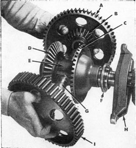
The main driving gears, with bevel pinions, are mounted on the crosshead. (See Fig. 52.) The bevel pinions mesh with bevel gears, one on each propeller shaft.
62
Figure 52-Crosshead, with Main Driving Gears and Bevel Pinions-(A) Main driving gear; (B) Bevel (driving) pinion; (C) After bevel gear; (D) Forward bevel gear; (E) Crosshead; (F) Thrust race; (G) Main driving gear bushings; (H) Strut; (I) Main driving gear
The arrangement is such that the unequal turning effort of the turbines is converted to equal turning effort on the propeller shafts. The bearings for the main driving gears and bevel pinions are bronze bushings, lack of space precluding the use of ball bearings.
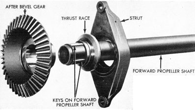
The drive from the engine to the propellers is conveyed through the propeller shafts, of which there are two. The forward propeller shaft is tubular in form. It passes through the strut, as shown in Figs. 53 and 54, and is keyed at its forward end to the after bevel gear. A self-aligning ball thrust bearing is interposed between this gear and the crosshead. A collar is turned on the shaft, just forward of the strut, and serves as a bearing for the inner race of the ball bearing in the strut. This bearing is designed to carry both radial and thrust loads. At its after end, this shaft is supported in a bearing in the after bulkhead. Its extreme after end is provided with keyways for attachment to the forward propeller sleeve.
Both the driving torque and the thrust of the forward propeller are carried through this shaft, the latter being partly resisted by the tendency of the bevel gear and pinion to separate under the driving load. The thrust of the propeller is somewhat the greater, and this difference in the forces is carried by the ball bearing to the crosshead, and by the crosshead to the turbine frame, thence to the turbine bulkhead. The shaft
Figure 54-Assembly of After Bevel Gear and Forward Propeller Shaft Assembly
has a spur pinion integral with it, just aft
the strut, for driving the gyro mechanism.
The after propeller shaft is solid, and is
carried within the forward propeller shaft.
At the crosshead, it runs in a floating
bronze bushing. At its forward end, the
shaft is keyed to the forward bevel gear. Interposed between the forward bevel gear and a bearing washer on the shaft at this point and the turbine spindle casing, is a ball-bearing thrust washer. The after end of the after propeller shaft is supported in bronze bushings between it and the forward propeller shaft.
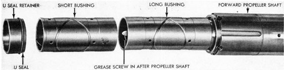
A grease retainer ring is installed in the forward propeller sleeve around the after propeller shaft to prevent loss of grease, and to minimize water leakage between the shafts into the afterbody. A U-seal and retainer are provided, as shown in Fig. 55, further to prevent leakage of water between the shafts into the afterbody. The
extreme after end of the after propeller shaft is provided with keyways for attaching to the after propeller sleeve, and a nut for securing the sleeve. The driving torque and thrust of the after propeller are carried through this shaft; the thrust, in addition to the tendency of the forward bevel gear and the pinions to separate, is taken by the ball thrust washer and carried by it to the spindle casing and through the turbine frames to the turbine bulkhead.
To prevent leakage around the forward propeller shaft, a U-seal and retainer are provided (see Fig. 56), which are secured to the after bulkhead bearing.
The propeller shafts pass through the after bulkhead of the afterbody and into the tail section of the torpedo, where the other parts of the propelling mechanism are assembled. The parts on the after bulkhead of the afterbody are shown disassembled in Fig. 56.
Figure 55-Propeller Shaft Bushings and U-Seal
64
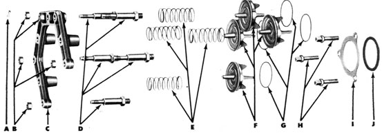
Figure 56-Parts Attached to After Bulkhead of Afterbody, disassembled-(A) Cotter pins (five used); (B) Holding nuts; (C) Valve bracket; (D) Studs; (E) Valve springs; (F) Exhaust valves; (G) Valve ring seals; (H) Holding screws; (I) U-seal retainer; (J) U-seal;
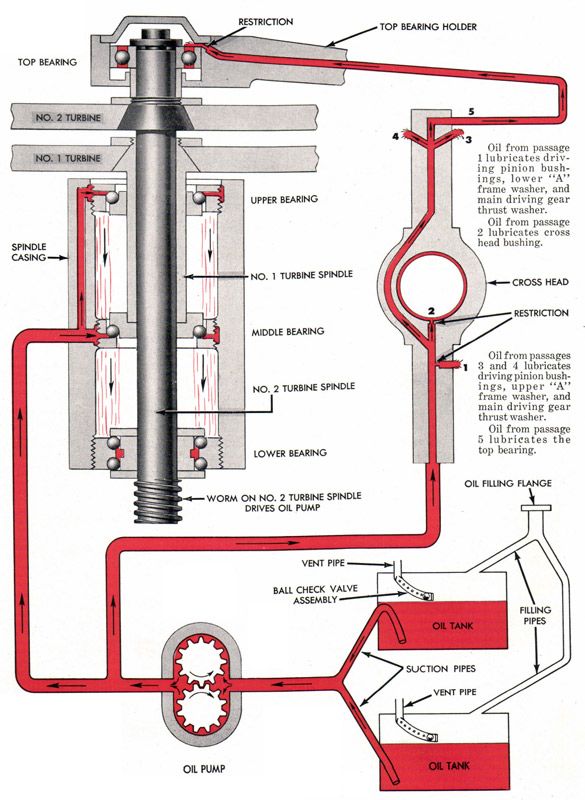
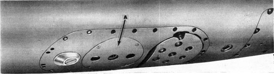
Oiling System
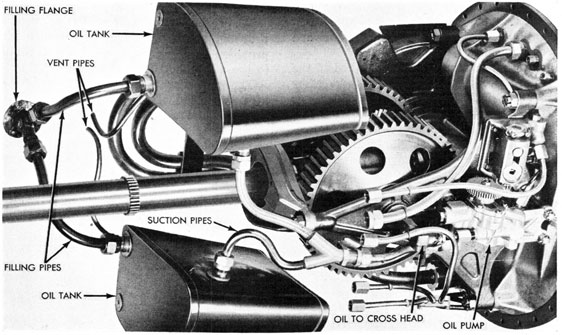
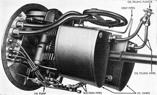
Two oil tanks provide a reservoir for the oil that lubricates the main engine, as shown in Figs. 57 and 58. They are located abaft the main engine and along the sides of the afterbody shell, conforming to the
contour of the shell outboard, and to the limits of the available space of the after-body interior.
The tanks are filled through the oil-filling flange, located on the top center line of the afterbody, and two filling pipes leading to
Figure 57-Oil Pump, Oil Tanks, and Connections, bottom view (Note: Tanks are secured to afterbody shell)
65
Figure 56 continued-(K) After-bulkhead bearing; (L) Glands; (M) Packing; (N) Stuffing boxes; (O) Washers; (P) Washer; (Q) After bulkhead; (R) Water outlet for cooling after bearing
the tanks. Vent pipes are located as shown in Fig. 58. Each vent pipe connects to a check-valve body, from which a perforated curved pipe runs into the tanks. The curved pipes contain ball checks, which drop into their seats when the torpedo is upside
down, and prevent the oil from running into the afterbody (see Fig. 60).
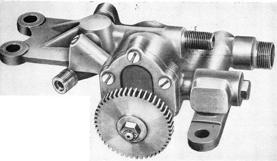
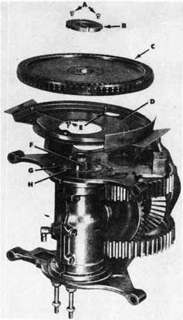
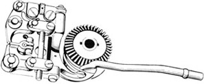
The oil pump (Figs. 59A, 59B, 59C, and 59D) is driven by the worm wheel, which meshes with the worm screwed to the lower end of the second turbine spindle. The oil is
Figure 58-Oil Pump, Oil Tanks, and Connections, viewed from port (Note: Tanks are secured to afterbody shell)
66
Figure 59A-Oil Pump, Assembled, Starboard View
carried from the suction side of the pump to the discharge side by a pair of gears which run in the oval shaped chamber. The meshing of the gears on the discharge side of the chamber drives the oil out from between the gear teeth into the discharge passage with considerable pressure. Two passages in the pump body, connected with the discharge passage of the pump, terminate
in nipples, the forward nipple being connected to a pipe leading to the turbine spindle casing (see Fig. 38), and the after nipple being connected by a fitting to the crosshead.
The oil entering the spindle casing flows into a groove surrounding the outer race of the middle bearing, and through a passage in the spindle casing, into a second groove
Figure 59B-Oil Pump, Assembled, Port View
67
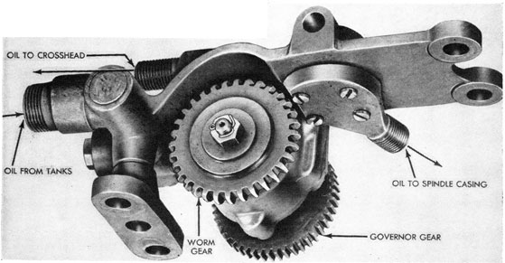
Figure 59C-Oil Pump, Showing Pump Gears-(A) Oil from tanks; (B) Oil to crosshead; (C) Worm gear; (D) Pump gears; (E) Oil to spindle casing
surrounding the outer race of the upper bearing. The outer races of the upper and middle bearings are drilled radially, thus permitting oil from the grooves in the spindle casing to enter the upper and middle bearings for lubrication. The excess oil from the upper and middle bearings falls to the bottom of the spindle casing, where it lubricates the bottom bearing (see Fig. 60).
Oil entering the lower end of the crosshead is distributed through suitable openings to the main driving gear and bevel-pinion bushings, and to the crosshead bushing, a restriction being provided to regulate the amount of oil entering the bushing. Oil reaching the upper end of the crosshead
enters a drilled bolt, which acts as a passage to the top bearing holder, which is drilled to allow the oil to reach the top bearing for its lubrication, after passing through a restriction.
The entire oiling system is shown in Fig. 60.
Smoke Prevention
Unless some means are taken to prevent it, these torpedoes will have a smoke wake in addition to the bubble wake. This is caused by engine oil entering the exhaust and being partly burned by the heat of the gases. It is desirable, for a war shot, to render the wake of the torpedo as nearly invisible as possible. To this end, it is necessary that all engine oil be excluded from the exhaust.
Underneath the turbine, and attached to the top engine frame, is a sheet-metal pan (the turbine oil guard) flared at its periphery (see Fig. 61). This pan, with the horizontal bulkhead, serves to prevent the splash of oil from the gears and turbines into the exhaust system. Also, above the upper turbine spindle bearing is a baffle or oil-deflector ring (see Fig. 61), which serves to prevent the entry of oil from the spindle bearing to the exhaust chamber.
The turbine oil guard, the bulkhead, and
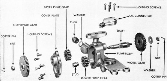
Figure 59D-Oil Pump, Disassembled
68
Figure 60-Oiling System, Diagrammatic View.
69
the oil deflector ring are provided to aid in the elimination of smoke. It should be noted, however, that if the torpedo is rolled over in preparation for a run when there is oil in the afterbody, the oil will enter the exhaust chamber, and the torpedo will smoke heavily until the oil is burned up. The above information applies to torpedoes which have not been converted in accordance with NavOrd Ordalt 1654, Smokeless Running Conversion. With this Ordalt accomplished the smoke wake of the torpedo is entirely eliminated. The changes involved in this conversion are as follows: Upon overhaul the parts of the main engine are coated with "Oildag," Lubricant (T), a 10% suspension of graphite in petroleum oil. No other lubrication than from the Oildag is provided; in place of Hot Running Torpedo Oil in the oil tanks, water is substituted. The graphite in the Oildag adheres to the gears and the bearings, providing the necessary lubrication for a complete run while the water acts as a coolant. To prevent the water from leaking through the oil pump and to control its application, there is a check valve interposed between the oil tanks and the oil pump, now a water pump. The check valve is operated by air pressure from the gyro reducing valve "Tee". Thus, since the check valve does not open until the torpedo is started, the water is sealed in the oil tanks until it is needed. With the lubrication system converted by Ordalt 1654, it can be seen that there is no oil fog or droplets present which will reach the exhaust chamber to burn and produce smoke. The introduction of water into the oil system not only keeps the bearings and gear train cool but tends to keep down the temperatures of the exhaust gases leaving the engine. For the general arrangement of the check valve installation, see Figures 221a and 221b.
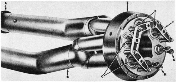
Exhaust System
The exhaust system (Figs. 62 and 63) is devised to carry off the turbine gases with the least back pressure, with the least circulation through the afterbody, and with the least amount of surface indication. The system consists of a semi-closed chamber above the turbines, two exhaust tubes leading aft, and branching into four tubes leading to exhaust ports in the after bulkhead; and hollow propeller sleeves with escape holes in their sides, through which the gases are expelled.
The turbine exhaust chamber is formed within the afterbody shell by vertical and horizontal bulkheads which, supplemented by the turbine oil guard below the turbines and the turbine bulkhead, form a semi-tight chamber.
The exhaust tubes are telescoped over short sleeves, with flanged collars, attached to the vertical bulkhead with screws. The after end of each tube is slipped into suitable openings in the after bulkhead and held in place by rolling a beaded projection into a recess cut around the opening. By removing the flanged sleeves and prying under the beaded ends, the tubes may be withdrawn from the afterbody.
Figure 62-Exhaust Tubes and Valves, Assembled-(A) Exhaust-tube thimbles; (B) Exhaust tube; (C) Exhaust-valve assemblies; (D) Depth-rudder rod connection; (E) After bulkhead; (F) Valve bracket; (G) Steering-rudder rod connection
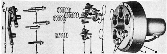
Figure 63-Exhaust-Valve Assembly, Disassembled-(A) Cotter pin (five used); (B) Holding nuts; (C) Valve bracket; (D) Studs; (E) Valve springs; (F) Exhaust valves; (G) Guide vanes; (H) Valve ring seals; (I) Rudder-rod stuffing boxes: (J) After bulkhead; (K) Water outlet for cooling after bearing
The four exhaust valves are supported in a bracket secured to the after bulkhead.
Three guide vanes (as shown at "G" in Fig. 63) on the inboard face of each valve insure proper alignment of the valve with its seat in the after bulkhead. A raised ring on the outboard face of the valve serves as a retainer for the forward end of the exhaust-valve spring. The tapered valve stem on the outboard face of the valve serves as a rough guide for the valve, and its
presence also facilitates the machining and lapping of the valve. Ring seals are provided on the valves as seats to prevent leakage of water into the afterbody while the torpedo is in a submerged tube. Since these ring seals burn off during the run, it is necessary to lap the valves to their seats for exercise runs.
Springs hold the valves on their seats until the exhaust gases build up to a pressure slightly greater than the surrounding water
pressure.
71
Chapter 5
THE TAIL SECTION
General Construction
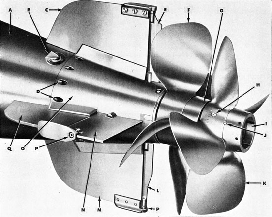
The tail section is shown in Figures 64A, B, C, and D. This section consists principally of those surfaces required to propel the
torpedo and to control it in its water travel. The moving parts of this section are actuated by the various mechanisms in the after-body. All the parts are mounted on the main
body of this section, called the tail cone. The parts which provide the propelling and controlling surfaces are the propellers, tail blades, and rudders. Means for connecting these parts to the afterbody, the steering
lines, and the propeller shafts are also included as parts in the tail section.
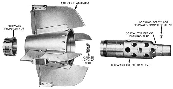
The body of this section is a truncated cone (tail cone) having two vertical and two horizontal tail blades riveted to it. The
Figure 64C-Tail, Disassembled
73
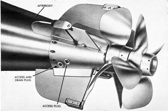
forward end of the tail cone is drilled for securing the tail section to the afterbody with joint screws. A shoulder in the after end contains tapped holes for the screws with which a bronze bearing (tail bearing) for the forward propeller sleeve is held in place.
The tail bearing supports the forward propeller sleeve, which in turn supports the after propeller sleeve by means of four bushings interposed between the sleeves. A grease container is provided in the after end of the tail. It connects with the grooves in the tail bearing and provides a means for packing the tail bearing. Removal of a plug gives access to the grease container.
The grease container described above is being replaced by a grease reservoir (shell) contained in the after propeller sleeve in torpedoes of new manufacture.
A grease (packing) retainer ring is installed in the forward propeller sleeve around the after propeller shaft to prevent loss of grease and entry of sea water, as described in Chapter 4.
Enclosed in the tail cone are the depth steering-rudder yokes, (Fig. 65), the rudder-adjusting rods and eyes, and the forward and after propeller sleeves. To the sleeves are attached the propeller hubs, on which the propellers are mounted. The after
propeller hub is made integral with the after propeller sleeve. The propellers are secured to their hubs with lock nuts and screws.
The after ends of the rudder-adjusting rods slip over studs in the yokes, and are secured by cotter pins, brass washers being interposed on the studs between the rudder-adjusting rods and the yokes. The forward end of each rudder-adjusting rod is threaded to receive an eye. Turning the eye serves to lengthen or shorten the adjusting rods. The adjustment is clamped by means of a clamp screw. The eyes are connected by linkages to the depth and steering engines. The steering rudders are designed to minimize rudder interference with the water ahead of the propellers. It will be noted that the lower section of the steering rudder is smaller than the upper, to minimize the tendency of a torpedo to heel during the turn on an angle shot.
At the center of the port side of the tail cone are graduations by means of which the depth-rudder readings are taken. A zero graduation is stamped on the starboard side for the purpose of aligning the top surfaces of the depth rudders. The depth and steering rudders (each made in two sections) are mounted in bearings directly abaft the tail blades (Fig. 64C).
74
Figure 64D-Tail, Cut-Away View
A. Tail Cone B. Tail-Blade Flanges C. Vertical Blade D. Steering Rudder E. Steering-Rudder Adjusting Rod, Eye, and Clamp F. Drain and Access Hole G. Grease-Packing Retainer Ring for Forward Propeller Sleeve H. Forward Propeller Sleeve I. After Propeller Sleeve
J. Propeller Sleeve Bushing (4) K. Tail Bearing L. Forward Propeller M. Forward Propeller Hub N. Forward Propeller Nut O. After Propeller P. After Propeller Hub (attached to after propeller sleeve) Q. After Propeller Nut R. Grease Reservoir (shell)
75
Movement of the rudders is effected by the rudder yoke through connection of the yoke to the rudder rods extending from the afterbody. The connecting piece is known as the rudder-adjusting rod and eye. The eye is adjustable on the rod through a clamped screw connection and it is accessible through access holes in the tail cone.
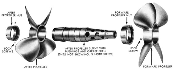
Propeller Sleeves
The propeller sleeves are short, hollow shafts, which connect to the propeller shafts extending through into the tail section from the afterbody. These propeller sleeves are part of the tail assembly and carry the propellers, as shown in Figs. 64C and MD.
The forward propeller sleeve is tubular in form, and connects at its forward end with the forward propeller shaft by means of keys which fit into keyways in the shaft, a neat slip fit being provided. The sleeve is further locked to the shaft by means of four holding screws.
The after end of the forward propeller sleeve is supported in the tail bearing secured to the after end of the tail cone. On the extreme after end of the forward propeller sleeve are mounted the forward propeller and hub. The sleeve has a shoulder forward of the tail bearing. There is no thrust contact between this shoulder and the tail bearing. A considerable longitudinal play is provided for this sleeve in order that the expansion of the forward propeller shaft, due to temperature in the afterbody, will not bind the bearing.
The after propeller sleeve is also tubular in form, and connects at its forward end with the after propeller shaft by means of keys fitting into keyways in the shaft. The sleeve is further locked to the shaft by means of a nut, which screws on the after propeller shaft and draws the sleeve up against a shoulder on the shaft. The after end of the after propeller sleeve carries a bronze bearing in the form of four separate bushings interposed between it and the forward propeller sleeve. On its extreme after end are mounted the after propeller and hub.
In torpedoes of new manufacture, a tubular grease reservoir (shell) (see Fig. 64D) is installed in the after propeller sleeve in order to improve the lubrication of the bearing surfaces in the tail. This method reverses the direction of the flow of the grease in relation to the center of rotation, and takes advantage of exhaust-gas heat to liquefy, and centrifugal action to force grease into the bearings.
A considerable space is provided between the sleeves within the tail cone; and, in addition, each sleeve has a series of large holes. The construction allows the exhaust gases to be expelled aft of the propellers, thereby preventing disturbance of the water forward of the propellers, and reducing surface indications of the torpedo wake.
Propellers and Hubs
The propellers are made of steel, each propeller having four blades. Each propeller has a steep tapered hole in the central body which fits a corresponding taper
76
on the propeller hub to which it is keyed. The propeller hub fits snugly over the after end of the propeller sleeve, and is keyed to the sleeve with one key. A large propeller nut forces the propeller on the tapered hub, and forces the hub into position on the sleeve. A slot in the forward propeller hub allows the hub to contract and grip the sleeve as the propeller nut is tightened. The propeller nut is prevented from turning by two headless locking screws, part of each screw being in the propeller nut and part in the propeller body.
The hub for the after propeller has a grease hole for lubricating the tail bearing and the four bushings between the propeller sleeves. Removal of a grease plug and washer provides access to the grease hole.
The grease cavity and grease plug referred to above are not used in torpedoes equipped with the new tail lubricating system described under propeller sleeves, above.
The after propeller hub is made integral with the sleeve, and the after propeller is secured to the after hub by a tight fit over the hub, and also by the after propeller lock nut. The after propeller is keyed to the hub, and the lock nut is held by two keep screws.
In torpedoes equipped with the new tail lubricating system, the hub for the after propeller has a grease hole for lubricating the tail bearing and the four bushings between the propeller sleeves. Removal of a grease plug and washer provides access to the grease hole.
77
Chapter 6
THE GYRO AND DEPTH MECHANISMS
General
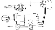
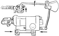
The gyro and depth mechanisms (see Fig. 66) are installed for the purpose of keeping the torpedo on its predetermined course and at the desired depth.
The gyro and gyro mechanism, by operating the steering rudders, correct any deviation of the torpedo to port or starboard. The depth mechanism, by operating the depth rudders, maintains the torpedo at the desired depth during its run.
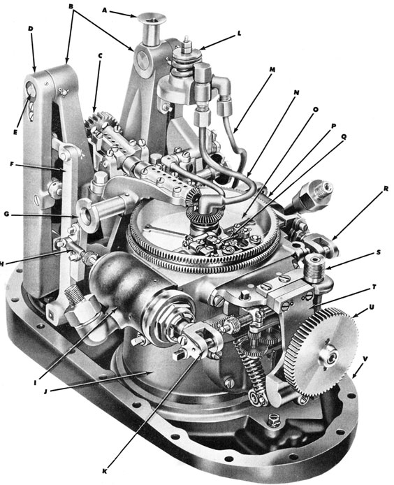
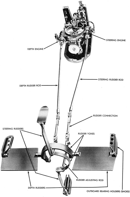
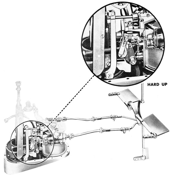
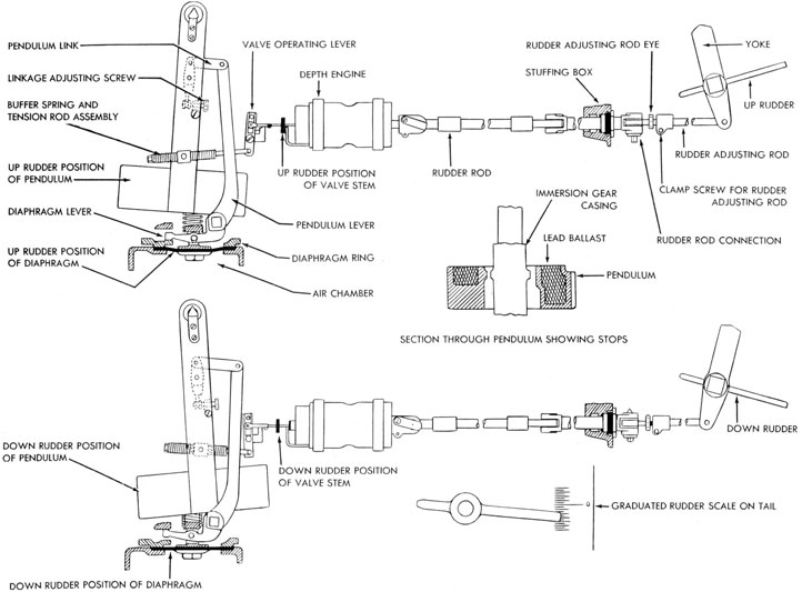
The two mechanisms are mounted on one base, as shown in the large illustration, Fig. 66, and also in Fig. 67, which shows the connections with the rudders.
The controlling feature of the gyro mechanism is the gyroscope, which is placed in the gyro pot, as a final step in getting a torpedo ready for a run. Similarly, the controlling feature of the depth mechanism is the hydrostatic diaphragm and pendulum unit. The basic principle employed in the gyro mechanism is the gyroscope's resistance to any change in the alignment of its axis of rotation.
There are two controlling elements in the depth mechanism: (a) The hydrostatic diaphragm, which brings the torpedo to and maintains it at its set depth; and (b) the pendulum, which aids the diaphragm and keeps the torpedo at its proper running attitude.
The gyroscope is described fully in Ordnance pamphlet Number 627A. The purpose here is to give only a brief general description of the gyroscope, more especially as it relates to the gyro mechanism; hence
reference should be made to OP 627A for complete details.
The gyroscope Mk 12-3 is used for the Torpedoes Mk 14 and Mk 23 Types.
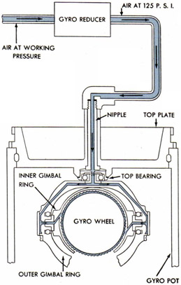
The gyroscope is composed of a gyro wheel and supporting gimbals, which are so arranged that the axis of rotation of the gyro wheel may assume any direction. The gyro wheel receives its initial rotation by a gyro spinning and unlocking mechanism, which automatically is disengaged from the wheel once it has been given its initial spin; thereafter the velocity of the gyro wheel is maintained throughout the run of the torpedo by means of low-pressure air (approximately 125 p.s.i.).
The gyroscope is installed in a housing (gyro pot) to which are attached the mechanisms necessary for steering the torpedo.
These various mechanisms will be de. scribed in the following pages of this chapter.
Gyroscope
The gyroscope (see Figs. 68A to 68E) is composed of the following parts:
1. The wheel and spindle, a thick rimmed monel-metal wheel accurately balanced on its spindle or axis, and rotating in the central plane of the gyroscope. This wheel is shown, with the inner gimbal ring, in Fig. 69. On the rim of the wheel are saw-tooth buckets on which air impinges, maintaining a constant rate of spin. Spur gears are machined on each enlarged section of the spindle. One of these meshes with a similar spur gear of the gyro spinning and unlocking mechanism while the gyro wheel is
78
Figure 66-Gyro and Depth Mechanisms, Assembled
A. Socket for spring adjusting spindle B. Depth-mechanism casing C. Pallet driving gear D. Pendulum E. Kife-edge bearing F. Pendulum lever G. Worm-shaft sockets (for angle setting) H. Valve connection I. Depth engine J. Gyro pot K. Piston fork
L. Gyro reducer M. Air from strainer holder N. Air for sustaining gyro spin O. Top plate P. Steering engine Q. Pallet mechanism R. Piston fork S. Gyro spin nipple T. Gyro spinning and unlocking mechanism U. Spinning turbine V. Base
79
Figure 67-Gyro and Depth Mechanisms, Showing Linkage to Depth and Steering Rudders
Figure 69-Gyro Wheel and Inner Gimbal Ring disassembled
A. Locking disc (free end) with screws for attaching
B. Inner gimbal (after half)
C. Balance nut
D. Wheel bearing "B"
E. Gyro wheel, showing pivot, spur gear, and saw-tooth buckets on wheel rim
F. Wheel bearing "A". Side opposite that shown is machined with socket to receive centering pin.
G. Inner gimbal (forward half). Note channels grooved into brackets at sides of ring; when the two rings meet, these channels form ducts to convey air to buckets on wheel rim.
H. Locking disc. Note locating dowels.
Figure 70-Outer Gimbal Ring, showing partial cut-away of air passages
being given its initial spin; the other gear is provided for balance. They gyro wheel is housed within a split casing called the inner gimbal ring (see Fig. 69) which, in turn, is pivoted within the outer gimbal ring (see Fig. 70). The gyro wheel spins on its own axis and holds to its original alignment, while the torpedo may swing and even revolve either horizontally or vertically without deflecting the axis of the gyro wheel from its original alignment.
2. The inner gimbal ring, shown in Fig. 69, is machined in the form of a hood, being thus designed to prevent air currents thrown off by the wheel from striking the gimbal rings and thereby setting up deflecting forces on the sensitive parts of the unit. The inner gimbal ring may be turned 360
Figure 71-Diagrammatic Drawing showing Path of Air which Sustains Gyro Wheel at a Constant Speed
82
Figure 72A-Gyro Cam Plate, Bottom View
Figure 72B-Gyro Cam Plate, Top View
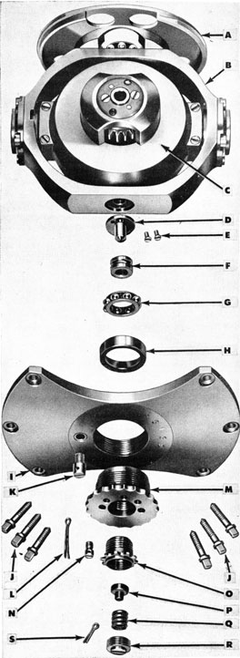
Figure 73 (at right)-Gyro, with Cam Plate attached, showing Bottom Head Assembly, and Bottom Bearing Assembly, disassembled. (A) Cam plate; (B) Outer gimbal-ring assembly; (C) Inner gimbal-ring assembly; (D) Bottom gimbal center or pivot; (E) Holding screw for "D"; (F) Inner bearing race; (G) Ball bearings and retainer; (H) Bottom bearing race; (I) Bottom head; (J) Holding screws for "I"; (K) Keep screw; threads into small hole in "I" after "M" is adjusted properly; (L) Cotter pin for "K"; (M) Bottom bearing holder; (N) Lock screw; may be threaded into any of five holes in "M"; (O) Adjusting body; receives "P", "Q", and "R"; (P) Spring button; bottom of "D" seats on upper face of "P"; (Q) Spring; (R) Plug; provides seat for "Q"; (S) Cotter pin for "N"
83
degrees in its bearing in the outer gimbal ring without interference.
3. The outer gimbal ring, which supports the inner gimbal ring, is shown in Fig. 70. In other words, the outer gimbal ring encircles and supports the gyro and inner gimbal-ring assembly. The upper face of the outer gimbal ring is machined for attaching the cam plate. Holes are drilled through the upper section of the outer gimbal ring for the passage of air to the side bearing sleeves, and through the inner gimbal centers to sustain the constant spin of the gyro as shown in Fig. 71.
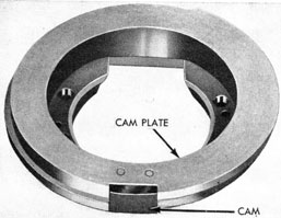
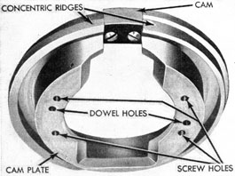
Cam Plate
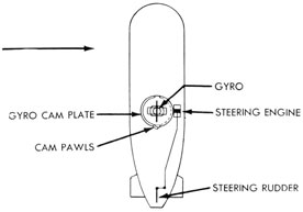
The cam plate (see Figs. 72A and 72B), through which the gyro controls the torpedo's mechanism for holding the torpedo to its course, is secured to the top of the outer gimbal ring, as shown in Fig. 68,its location being determined by dowels projecting from the top of the ring (see Fig. 70). The cam plate has a central opening to permit engagement of the top outer gimbal-ring bearing with the bearing race in the top of the gyro pot.
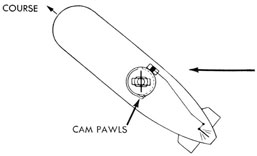
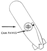
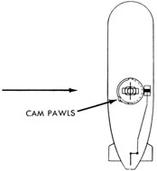
A cam is secured to the outer circumference of the cam plate in line with the axis of the gyro wheel. This cam serves to throw the pallet blade to right or left as the torpedo changes its direction relative to the axis of the gyro, giving right and left rudder respectively. The rim of the cam plate is machined with concentric ridges and grooves, so that the cam pawls will be thrown in the direction necessary to restore the torpedo to the course, at which time the cam pawls will straddle the cam.
The Gyroscope Mk 12-3 is shown in Fig. 68 (locking-end view) with the cam plate in place, this being the after side of the gyro and cam plate, and showing the socket in the gyro wheel bearing into which the head of the centering pin inserts when the spinning and unlocking mechanism is in locked position. Fig. 73 also shows the bottom center bearing assembly, disassembled, together with the bottom head and related parts, the bottom head being assembled on the gyro pot after the gyro is installed in the pot.
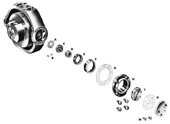
Fig. 74 shows the side bearing assembly and inner gimbal center bearing assembly, disassembled.
Figure 74-Side Bearing Assembly and Inner Gimbal Ring Bearing, Disassembled
A. Gasket B. Screws for gimbal center C. Gimbal center D. Inner bearing race E. Ball bearings and retainer F. Side-bearing outer race G. Gasket
H. Side-bearing sleeve I. Screws for sleeve J. Adjusting plate (for taking up end play) K. Gasket L. Side-bearing locking disc M. Screws for locking disc
84
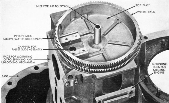
Figure 75-Gyro Pot with Top Plate
Gyro Pot
The gyro. pot (Fig. 75) is a cylindrical bronze drum which houses the complete gyroscope. It carries the spinning and unlocking mechanism assembly on its after side. On the upper port and starboard sides are bosses for mounting the depth and steering engine.
The spinning and unlocking mechanism gives the gyro its initial spin; the pallet
mechanism takes "steering orders" from the gyro and transmits those orders to the steering engine, which carries out the orders by regulating the steering rudders.
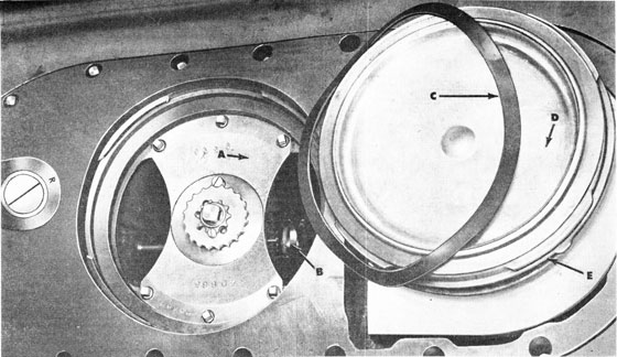
The gyro clamp plate and cover (see Figs. 76A and 76B) close the lower opening of the gyro pot.
The clamp plate has a flanged seat on its outer circumference which fits a similar seat in the bottom of the gyro pot, being made water-tight by means of a gasket. In the center of the clamp plate is a hole, drilled and tapped, for the screw which holds the clamping plug.
The clamp plate cover has a four-section
interrupted ridge on its circumference which fits over a corresponding interrupted ridge on the gyro pot. The clamp plate is rotated until the ridges are in line, after which the cover may be clamped against its seat by tightening the plug.
The top of the pot is machined with a tight joint permitting a turning of the top plate for angle settings. The center of the top plate is built up to form a recess for
the top bearing of the gyro outer gimbal ring. A passage is drilled down through this section, providing for the introduction of air into this bearing to sustain the spin of the gyro wheel.
Two segments are extended from the lower end of the inner wall of the gyro pot for the support of the bottom head. The complete gyroscope is supported through its vertical axis between a bearing in this bottom head and a bearing mounted in the gyro top plate.
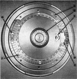
The top plate (see Fig. 75), which closes the top of the gyro pot, and on which the pallet mechanism is assembled, is held
against a lapped surface on the top of the gyro pot with retainer plates (see Fig. 77). This top plate can be moved through 160 degrees left or right to permit setting of the gyro pot for angle shots. The plate is machined with a double row of teeth on its outer periphery, the upper being the worm rack for side setting, and the lower being a pinion rack for setting by means of the bottom setting socket (for above-water tubes only). The side setting socket (in combination with the side gears)
permits setting for angle shots from the exterior of the torpedo in a tube. This complete mechanism, called the angle-fire setting device, will be described later in this chapter.
Figs. 78A and 78B show the gyro and related mechanisms in place, Fig. 78A being a side view, and Fig. 78B a view from aft. The pot has been cut away in these two views to show how the various units relate to each other.
Figure 76B-Gyro Clamp Plate and Cover (A) in place
86
Figure 77-Interior of Gyro Pot-(A) Bottom head; (B) Top bearing holder; (C) Cam pawls; (D) Spinning gear of spinning mechanism; (E) Stop; (F) Retainer plate; (G) Marker
Figure 78A-Gyro and Related Mechanisms in Place, side view. Figure 78B (below) shows view from aft
Figure 788-Gyro and Related Mechanisms
in Place, viewed from aft
A. Cam plate from port side, showing port concentric ridge
B. Boss for depth engine
C. Spinning gear; meshed with spur gear at locking end of gyro
D. Centering pin; is engaged in socket on outer side of gyro wheel bearing "A"
E. Inner gimbal ring sleeve
F. Locking disc
G. Gyro spinning and unlocking mechanism frame
H. Gyro top plate
I. Retainer plates
J. Top plate teeth; mesh with worm
K. Cam pawls
L. Cam plate
M. Cam
N. Top bearing holder
O. Inner gimbal ring
P. Spur gear
Q. Locking disc
R. Inner gimbal-ring bearing
S. Outer gimbal ring
T. Bottom outer gimbal-ring bearing
U. Bottom head
V. Renewal plate
87
Gyro Spinning and Unlocking Mechanism
A gyroscope accomplishes its purpose only when it is spinning at a very high rate of speed. It is the function of the gyro spinning and unlocking mechanism to give the gyro the initial spin (approximately 20,000 revolutions per minute) while holding the gyro firmly in position. Having supplied this initial spin, the mechanism must then be released from the gyro so that the latter will spin freely, and it must accomplish this without disturbing the gyro.
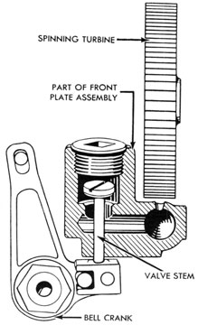
The gyro spinning and unlocking mechanism is assembled in a spinning-gear frame (see Figs. 79A and 79B), which is attached to the after side of the gyro pot, and in a front plate assembly attached to the spinning-gear frame. The front plate assembly has radial holes which direct the
high-pressure air upon the teeth of the spinning turbine. Fig. 66 is a view of the spinning and unlocking mechanism in place on the gyro pot.
The essential features of the spinning and unlocking mechanism are: (a) the spinning turbine and impulse mechanism, Figs. 80A, 80B, and 80C; (b) the centering feature, Fig. 81; (c) the locking and unlocking gear train, Figs. 82A and 82B; and (d) the spinning gear duration-adjustment feature, Fig. 83; also see Fig. 82B.
Centering Features
To hold the gyro rigid with the spur gears of the spinning shaft and gyro in proper mesh during the initial spin, the gyro wheel is held in position by a centering pin, the ball end of which engages in the hollow center of the ball-bearing
Figure 79A-Gyro Spinning and Unlocking Mechanism, Locked, View from Port Side. The mechanism mounted on the gyro is shown in Fig. 66
Figure 79B-Gyro Spinning and Unlocking Mechanism, removed from gyro pot, as it appears after it has supplied the gyro's initial spin and is disengaged from if. View from port side
Figure 80A-Operation of Spinning Turbine, diagrammatic drawing-(A) Spinning turbine; (B) Spinning sleeve and shaft assembly; extends to mesh spinning gear with gyro spur gear; (C) Gyro wheel; (D) Centering pin; (E) Nozzles
Figure 80C-Impulse valve-Locking of the spinning gear in mesh with the gyro automatically opens the impulse valve, through which air is passed to the nozzles for the spinning turbine. Valve closes when the mechanism unlocks.
Figure B0B-Showing Relation Between Spinning Shaft and Sleeve Assembly and Centering Pin, diagrammatic drawing (A) Spinning-shaft controlling sleeve; (B) Upper rack; toe "C" engages and disengages centering pin with gyro-wheel bearing socket; (C) Toe of upper rack; (D) Pinion; (E) Centering pin
cup for the wheel. (See Figs. 78A and 80A.) This centering pin is located in a separate steel housing rigidly secured between the spinning-gear frame and the front plate. A rack is machined on the upper side of the housing. The centering pin is operated by a toe extending from the forward end of the upper rack on the controlling sleeve.
Operation of Gyro Spinning and Unlocking Mechanism
The operation of the complete spinning and unlocking mechanism is as follows: With the locking of the mechanism, the spinning-shaft sleeve is moved in until the toe of the unlocking bar catches and holds it in the spinning position. The turbine wheel is then lined up over the nozzles; the centering pin is engaged in the forward ball cup of the gyro wheel; the spinning gear engages the spur gear on the gyro wheel spindle; the pinion on the locking and unlocking gear train is engaged with the teeth in the unlocking rack; the impulse valve is held clear of its seat; and the unlocking spring is placed under heavy compression by the spring bell crank. The gyro is then ready for a spin.
89
Figure 81-Operation of Locking and Centering Feature, diagrammatic drawing. To engage spinning gear and centering pin, the bell crank (A) is advanced by means of the locking lever (B). Pinion (C) carries the upper rack with it, which in turn extends sleeve (F) and advances the centering pin (H). When the mechanism unlocks, the spring (G) reverses travel of upper rack; spinning gear releases before toe or rack disengages centering pin from gyro-wheel bearing.
A. Spring bell crank B. Locking lever C. Pinion D. Upper rack E. Lower rack F. Controlling sleeve G. Spring H. Centering pin
Figure 82A-Locking and Unlocking Gear Train
Figure 82B-Unlocking Bar, Spring Lever and Hand Trip
Figure 83-Duration-Adjustment Feature
Figures 82A, 82B, and 83-Diagrammatic drawings illustrating operation of spinning and unlocking mechanism. (A) Unlocking rack, releases spinning shaft when thrust against "C"; (B) Spring lever, returns "A" to left after unlocking action; (C) Unlocking bar, releases "D" when moved to right by "A"; (D) Upper rack; (E) Hand trip, cam at top locks "C" against "D" and releases It when lever at bottom is moved by hand; (F) Reduction gear train, advances "A" to right as spinning shaft "G" revolves, until "C" is contacted; unlocking of mechanism then releases "A" for return; spinning shaft and sleeve with rack "D" snap to unlocked position, "0" carrying "H" with it; (G) Spinning shaft; (H) Centering pin; (I) Duration-of-spin adjustment; through lever "B", positions rack "A" so more or less teeth are engaged by pinion of gear train "F", controlling time required to advance rack to unlocking point.
90
ANGLE SHOT
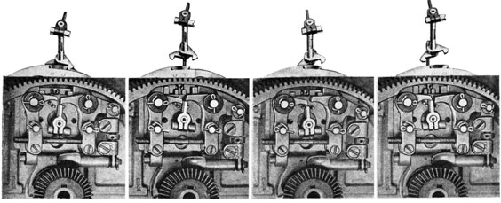
Torpedo running on desired course. Cam pawls now in line with gyro axis. Torpedo straightened out on course and steering rudders oscillating in normal manner. Gyro axis still parallel to original position.
Torpedo running. Steering rudders turning torpedo to bring cam pawls into line with gyro axis. Gyro axis still parallel to original position.
Torpedo ready to be fired on angle shot. Gyro-mechanism top plate rotated to desired angle, thus setting cam pawls off center of gyro cam plate by same angle.
Torpedo ready to be fired on straight shot. No angle set. Cam pawls in line with gyro axis.
Figure 84-Angle Shot, Functional Diagram, showing action of the gyro, pallet, and rudder (read from bottom up).
91
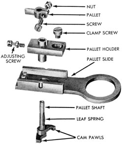
Figure 85-Pallet Mechanism with Linkage to Steering Engine-(A) Adjustable connection; (B) Pallet; (C) Pallet pawls; (D) Cam bevel gear; (E) Valve rock-shaft arm; (F) Driving spindle and bevel pinion; (G) Bracket for driving spindle; (H) Driving connection; (I) Bracket tor pallet driving gear; (J) Adjusting head; (K) Counter weight on rock shaft; (L) Valve connection arm; (M) Valve rock shaft; (N) Bell crank; (O) Connection spool; (P) Pallet driving gear
Upon launching of the torpedo, when the starting valve lifts, a blast of air at flask pressure is admitted through the impulse valve and the turbine nozzles of the gyro spinning and unlocking mechanism, spinning the turbine wheel. While the turbine wheel is being spun, the unlocking rack, actuated by the unlocking gear train, travels toward the unlocking bar until, at the end of its travel, the toe of the unlocking rack pushes the unlocking bar clear of the spinning-shaft sleeve. The pressure of the unlocking spring against the spring bell crank, augmented by the force exerted by the impulse-valve stem against the toe on the valve bell crank, causes the instant withdrawal of the spinning-shaft sleeve. This disengages the spur gears and the unlocking-gear pinion, closing the impulse
valve, and finally withdrawing the centering pin. The spinning gyro is now free, having accomplished the purpose of the spinning and unlocking mechanism for the run.
Pallet Mechanism
In Fig. 84 a diagrammatic drawing is shown illustrating the action of the gyro, pallet, and rudders in guiding the torpedo on its course.
The course of the torpedo is controlled by the steering rudders, which are operated by the steering engine. The directive force is relayed from the gyro wheel to the steering-engine valve by means of the pallet mechanism. This pallet mechanism is so arranged in coordination with the cam on
the cam plate (which is attached to the outer gimbal ring of the gyro) that the rudders are operated to correct the deviation recorded by the gyro.
The pallet mechanism is carried on the top plate, as shown in Fig. 85. It is so arranged that motion will be transmitted from the gyro to the steering-engine valve without disturbing the gyro. This is accomplished by intermittent light contact of small cam pawls with the cam (see Fig. 78B).
Figures 87B to 87K -The drawings and explanatory text given below present a progressive explanation of how the pallet mechanism operates to control the operation of the steering engine, and through it the steering rudders.
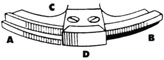
Figure 87B -Fastened to the gyro, cam plate "C" holds cam "D" with its center on the firing course. For later reference, "A" is port concentric ridge, "B" is starboard concentric ridge.
Figure 87A -Operation of Pallet Mechanism
Top view above shows cam pawls forward with port pawl engaging port groove, causing pallet blade to swing to position opposite port pallet pawl. Lower view shows pallet blade in position for thrust against pawl.
Pallet assembly has been thrust aft by motion of pallet slide; pallet blade pivots port pallet pawl aft. To avoid disturbance of gyro, pallet slide is kept in constant motion fore and aft, so contacts with cam are momentary.
Pallet assembly has been brought back by motion of pallet slide; torpedo is now assumed to have swung off course to starboard. Starboard cam pawl engages starboard groove in cam plate, and pallet blade swings to starboard.
The pallet blade having received its "steering orders" through momentary contact of the cam pawls with the cam and plate, the pallet moves aft, pushing the toe of the starboard pallet pawl aft.
93
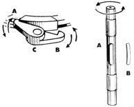
Figure 87C -Cam pawls "A" and "B" have a span just over the width of cam; if put in contact with cam with torpedo off course either way, one pawl or the other will drop into recess above ridge to which it is opposite. "C" receives pallet shaft "A" (at right); pawls are pinned to shaft and oscillate it to right or left. Leaf spring "B" lies in recess in shaft to prevent it from chattering in pallet holder.
Figure 87D -Pallet (at left) mounts at top of pallet shaft and clamps to it, with blade facing aft and at right angles to the oscillating plane of the cam pawls.
Figure 87E - At left, cam pawls, pallet shaft, and pallet are assembled; movement of cam pawls to right or left due to contact with cam or cam plate results in corresponding movement of pallet blade. Contact of cam pawls with the cam must be brief to avoid disturbance to the gyro; hence holder for pallet shaft assembly rides in a pallet slide (see Fig. 86).
Figure 87F- The pallet blade, having taken a right or left hand throw from the cam pawls, is advanced by movement of the pallet slide and moves one or the other of two pallet pawls about its pivot; at left is left hand or port pallet pawl.
Figure 87G -At right is right hand or starboard pallet pawl with pallet blade thrusting against it. The pallet pawls are positioned so that if cam pawls straddle cam, pallet blade passes between pallet pawls.
Figure 87H -To further pass on the directional motion set up by the cam and cam pawls, an "extender" is mounted on the left hand pallet pawl; an arm pinned to the extender pivots a bell crank in an up-and-down movement, as the
arm is given a back-and-forth movement by the extender. A linkage arrangement (Fig. 87I) results in the left hand pallet pawl moving forward when the right hand pallet pawl is thrust aft by the pallet blade.
Figure 87I
Figure 87J -To complete the steering process, when the port cam pawl is thrown aft by the pallet blade the bell crank throws the connection spool and the valve rock shaft arm downward, which, through the linkage, results in a forward motion of the steering engine valve and aft movement of the piston, as shown by the arrows; the rudders are then thrown hard to port.
Figure 87K-When the starboard cam pawl is thrown aft by the pallet blade, the motion of the connection spool and the valve rock shaft arm is upward, and the steering engine valve moves aft, the piston forward, as shown by the arrows; the rudders are then thrown hard to starboard.
The cam pawls are carried on a small shaft known as the pallet shaft (see Fig. 86).
When the torpedo course varies on either side of the axis of the gyro, one of the cam pawls will have moved into line with and will contact the cam, imparting a slight rotary movement to the pallet shaft, thus actuating the steering engine and steering rudders through the pallet mechanism (see Fig. 85).
94
Figure 88A-Steering Engine, Assembled, showing Linkage to Valve Rockshaft
When the torpedo course coincides with the gyro axis, the cam pawls will straddle the cam, thus centering the pallet blade. In this position, the blade will pass between the points of the pallet pawls, and no action will be transmitted to the steering rudders.
A progressive explanation of how the pallet mechanism operates to control the
operation of the steering engine, and through it the steering rudders, is given in the drawings and the accompanying explanatory text in Figs. 87A to 87K.
Steering Engine
The steering engine (see Figs. 84A, 84B, 89A, and 89B) is the mechanism by which
Figure 89A - Steering Engine,
cut away to show positions of
valve and piston when steering
rudders are hard over to starboard- (A) Passage tor exhaust of piston ring leakage; (B) Piston; (C) Adjusting washer which controls engine stroke; (D) Air inlet chamber; (E) Valve; (F) Exhaust port. Note that when valve is aft, piston is forward.
the directive force of the gyro is multiplied to give sufficient power for effective operation of the steering rudders to correct deviation recorded by the gyro. The engine has a single cylinder (see Figs. 89A and 89B), with a piston operated by the admission of air at reduced pressure at either end, the air being admitted through a valve operated by the pallet mechanism.
Steering Line
The portion of the steering-rudder operating mechanism between the steering engine and the rudders is called the steering
line. The motion of the steering engine is transferred to the steering rudders through the steering line, as shown in Fig. 67.
With the steering engine piston moving aft, the rudder rod is being pushed in the same direction, changing the angle of the rudder yoke, with a consequent movement of the steering rudders to port. The forward movement of the steering engine piston would have the reverse effect, changing the angle of the rudder yoke so the movement of the steering rudders would be to starboard.
An adjustable extension on the steering rod between the bulkhead connection and
Figure 89B-Steering Engine in position which results in rudders assuming hard-over-to-port position. Piston and valve have reversed their relative positions. Note how control chamber in valve permits flow of incoming air through hand intake channel to cylinder, while chamber at left-hand end of valve opens channel for exhaust (compare with Fig. 89A).
96
Figure 90-Gyro Reducing Valve, disassembled and assembled
A. Lock nut B. Nut C. Spring washer D. Spring E. Valve stem F. Valve body G. Diaphragm
H. Washer I. Nut J. Plug K. Cotter pin L. Valve assembled (Reduced) M. Inlet N. Outlet
the rudder yoke provides a means for adjusting the steering rod for equalizing the port and starboard positions of the rudders.
Gyro Reducing Valve
The gyro reducing valve (see Fig. 90) reduces the air pressure from approximately 450 p.s.i. and delivers the air at approximately 125 p.s.i. to the gyro to maintain its constant spin.
Angle-Fire Setting Device
The angle-fire setting device shown in Fig. 91, by rotating the gyro top plate, sets the desired angle between the pallet pawls and the cam on the gyroscope, and thereby the angle through which the torpedo will run. This action is shown diagrammatically in Fig. 84, with the accompanying text. The later Torpedoes Mk 14 Type are fitted with side setting devices only; changes from side setting to bottom setting cannot be accomplished in service without major modifications.
The top plate is rotated by a worm carried in a bracket attached to the gyro pot (Fig. 92) and meshing with the teeth cut around the outer periphery of the top plate. The flanged ends of the worm shaft and the sockets attached to the ends of this shaft are machined for connecting with the index levers. Connection from the side setting sockets to the index levers, and thus to the worm for indexing the gyro pot, is made through the gears and shafts as shown in Fig. 91. By turning the setting socket from either side of the torpedo, motion will be imparted to the forward gyro index gear, and through the index gear and lever to the index worm spindle and worm, the worm rotating the gyro top plate. With the torpedo in the tube of a submarine, the above outlined operation is accomplished through control mechanisms on the tube, without the necessity of removing the torpedo from the tube.
Depth-Control Mechanism
The depth-control mechanism, or the immersion mechanism as it is also called (see
97
Figure 91-Angle-Fire Setting Device and Gyro Index Gears
Figure 92-Angle-Fire Setting Bracket and Countershaft Assembly, Disassembled-(A) Screws and washer for securing adjusting head to valve rock shaft; (B) Adjusting head; (C) Valve connection arm; (D) Bearing cap and screw; (E) Socket; (F) Worm spindle; (G) Valve rock-shaft arm; (H) Valve rock shaft; (I) Spring button; (J) Spring; (K) Bearing cap and screw; (L) Driving spindle; (M) Worm; (N) Bracket for driving spindle; (O) Lock screw; (P) Socket; (Q) Nut
98
Fig. 93), maintains the torpedo at the desired depth during its run. Its function is accomplished by two horizontal rudders, acting as one, mounted on the after ends of the horizontal tail blades, just forward of the propellers, their inner ends being secured to the rudder yoke in the tail. The rudder yoke, in turn, is connected by a linkage to the depth-engine piston fork. These connections, as well as the operation of the depth mechanism, are shown in Fig. 93; also in Figs. 94A and 94B.
The piston of the depth engine is operated by air at reduced pressure, and is controlled by a very sensitive valve located inside the piston. This valve is connected, by means of a system of levers, to the pendulum of the depth-control mechanism; and the pendulum, in turn, is connected to the diaphragm through the depth-spring socket by interconnected levers and links. As thus connected, the pendulum, the diaphragm, and the depth engine valve move simultaneously.
Motion of the valve may be produced by the pendulum when the torpedo inclines from the horizontal, or by the hydro-diaphragm when the torpedo is off the set depth, or by both in combination. In any case, the pendulum and the hydro-diaphragm move together, each exercising a modifying effect on the other. This latter is what is known as the Uhlan principle.
The diaphragm is acted upon by pressure of sea water while the torpedo is running. The diaphragm is held against this seawater pressure by the depth spring, connected to the lower depth-spring socket, plus atmospheric pressure in a pressure-tight air chamber. Since the pressure in the air chamber is constant for all practical purposes, the depth-spring loading controls the running depth of the torpedo. The pendulum is acted upon by gravity, and serves to limit the angle of inclination at which the torpedo may seek set depth, and at the same time tends to steady the torpedo at set depth.
The depth-control mechanism is assembled on the same base as the gyro mechanism, as shown in Fig. 66, and is therefore
removed from the afterbody with the gyro mechanism.
From the time the torpedo is launched until it reaches set depth, the action of the depth mechanism is as follows:
Assuming that the torpedo is launched from a submarine tube at some depth under water with the tube flooded (sea pressure in the tube and therefore acting on the hydro-diaphragm), as a result of initial launching momentum, the pendulum will be swung aft, calling for a down-rudder action, thus causing varying depths of initial dive of the torpedo. As soon as this initial dive is in progress, the pendulum will swing forward and, in combination with the action called for by the pressure on the hydro-diaphragm, will cause the torpedo to rise and seek set depth as the speed at which the torpedo control is effective is attained. As the torpedo rises and approaches set depth, the hydro-diaphragm and the pendulum will cause the rudders to assume gradually their neutral position. The forward momentum of the torpedo, however, will carry it somewhat above set depth. The hydro-diaphragm and pendulum will then give "down-rudder". After a time the variations from set depth will level out, and the torpedo will run at the desired depth. The pendulum and the hydro-diaphragm, working in conjunction, will control the rudders to correct for any deviations from set depth.
Pendulum
The pendulum is suspended on knife-edge bearings. Its base is ballasted with lead to obtain the necessary mass for smooth control of the depth rudders. The fore-and-aft movement of the pendulum relative to the torpedo is limited by stops. Retainer plates, set in the pendulum arms, make near contact with the under side of the knife-edge bearings and prevent the pendulum from jumping or pounding excessively.
The pendulum may be subjected to severe side forces, and in order to prevent damage to its supports, the under side of the pendulum has guides which just clear rollers attached to the depth-mechanism casing (see Fig. 95-2 and 3). Normally
1. Pendulum bracket or depth-mechanism casing 2. Pendulum 3. Pendulum link 4. Linkage adjusting arm 5. Depth-spring adjusting spindle 6. Linkage adjusting screw 7. Idler gear 8. Depth-spring adjusting-screw gear 9. Depth-spring adjusting screw 10. Tension rod and buffer spring assembly
11. Depth spring 12. Diaphragm-lever shaft 13. Diaphragm lever 14. Diaphragm 15. Diaphragm plate 16. Clamp nut 17. Air chamber 18. Plug 19. Diaphragm ring
100
Figure 94A-Operation of the Depth Mechanism, with Down Rudder
these guides do not make contact with the rollers, but any heavy side forces which might otherwise cause the pendulum to lift on its supports will bring one of the guides against its mating roller, which absorbs the shock. The clearance between the guides and mating rollers is such that the rollers do not contact the guides when the casing is not inclined more than 30 degrees to either side. Figs. 95A to 95H show views of the pendulum and other related parts of the depth mechanism. These views are arranged to give a clear picture of the pendulum and its operation.
Hydro-Diaphragm
The hydro-diaphragm is shown in Fig. 96. The diaphragm is of oil-resistant, rubberized fabric, clamped on its outer edge, between the diaphragm ring and the air chamber. The parts and assembly are shown in Fig. 96.
Water enters to exert its pressure upon the upper side of the diaphragm through an inlet pipe, the open end of which is located in the midship section. A small hole is drilled in the diaphragm ring to vent air which may be trapped in this chamber by the incoming water.
101
Figure 94B-Operation of the Depth Mechanism, with Up rudder
The diaphragm has a very limited movement, which is so multiplied that the ratio of the valve movement to the diaphragm movement is 18 to 1. The small amount of free diaphragm area between the outer and inner supported areas gives ample flexibility to the small movement required up to a 50-foot depth setting.
Depth-Setting Mechanism
The depth-setting mechanism (see Figs. 97A and 97B) is a device for setting the
tension of the depth spring to correspond with the water pressure at the desired running depth. When the torpedo reaches the set depth, the force exerted by the water on the diaphragm balances the force exerted by the spring on the diaphragm. The setting is indicated on a graduated dial, called the depth index wheel.
There are two major units in the depth setting mechanism: the depth-index flange assembly, and the spring-socket assembly. The depth-index flange contains all the parts secured to the afterbody shell, and in its center is the depth-index spindle which passes through a stuffing box in the flange.
102
Figure 95-Depth Mechanism, in various stages of assembly, showing the Diaphragm, Pendulum, and Related Parts (also see Fig. 96).
Illustration 1 shows pendulum with (A) Knife-edge bushings; (B) Pendulum link; (C) Linkage-adjusting screw; and (D) Lead ballast.
Illustration 2 shows depth-mechanism, casing, or pendulum bracket, with (A) Water inlet; (B) and (C) Pendulum guide rollers.
103
Figure 96-Depth Mechanism showing Diaphragm and Depth-Setting Mechanism assembled and disassembled: 1, pendulum and casing assembled; 2, assembly from below; 3, assembly from above; 4, parts disassembled. (A) Pins; (B) Knife-edge bearings; (C) Retainer plate; (D) Screws; (E) Buffer-spring assembly; (F) Depth-setting mechanism assembly; (G) Spring-adjusting screw; (H) depth spring and socket assembly; (I) Cotter pin and washer; (J) Pin; (K) Diaphragm lever; (L) Pendulum and diaphragm-level shaft; (M) Gasket; (N) Diaphragm ring; (O) Diaphragm; (P) Diaphragm plate; (Q) Nut; (R) Cotter pin; (S) Cotter pins; (T) Adjusting-linkage pin; (U) Adjusting arm; (V) Link; (W) Pin; (X) Pendulum lever; (Y) Taper pin.
Illustration 3 shows under side of pendulum, with (A) Transportation-screw hole, and (B) Pendulum guides.
Illustration 4 shows pendulum suspended on knife-edge bearings in bracket, with (A) Taper pins and cotter pins securing knife-edge bearings in casing arms, (B) Socket for spring-adjusting spindle, (C) Knife-edge bearings, (D) Retainer plate, (E) Spring-adjusting spindle, (F) Spindle gear, (G) Water inlet, and (H) After section of pendulum.
Illustration 6 shows assembly ready for mounting on diaphragm ring and diaphragm, with (A) Pendulum lever, (B) Buffer spring and tension rod
assembly, (C) Diaphragm and pendulum-lever shaft, and (D) Idler gear.
Illustration 7 shows under side of pendulum assembly before addition of diaphragm assembly, with (A) Pendulum lever, (B) Diaphragm lever,
(C) Lower depth-spring socket, and (D) Depth spring. Note recess in casting above diaphragm lever "B"; diaphragm lever pivots within this. recess on the pendulum-lever shaft.
Illustration 8 shows assembly complete, with (A) Diaphragm, (B) Nut, (C) Diaphragm plate, (D) Diaphragm ring. Note that diaphragm ring "D" is mounted so projection on inner circumference provides lower bearing surface for diaphragm lever (see "B" in illustration 7). Also note that lower end of nut "B" is tapped to receive hook rod for testing weight.
104
Figure 97A-Depth Setting Mechanism Assembled
The lower end of the spindle is geared to the side-gear spindle to which is attached a spring-loaded socket squared to fit the spring-setting socket. This socket operates through a spindle and gearing to adjust the tension set on the depth spring. The depth-index spindle and gear assembly transfer the movement for setting the depth spring from the outside of the afterbody to the depth mechanism.
The depth-index wheel (see Fig. 97B) is a graduated dial which takes on a reduced motion from the depth-index spindle through a gear system. The depth index should never be set below zero.
Depth-Engine
The depth engine (see Figs. 98A and 98B) is mounted on the port side of the gyro pot (see Fig. 67). Its function is to move the depth rudders as required to keep the torpedo at its set depth. The operating linkage between the pendulum, hydro-diaphragm, and valve is shown in Figs. 93, 94A, and 94B. The operation of the depth
Figure 98A-Depth Engine, Assembled (See below for parts disassembled).
engine is shown diagrammatically in Figs. 99 and 99A, also 94A and 94B.
It is a follow-up type engine controlled by a sensitive internal valve. This valve receives its action from either the pendulum
or the diaphragm through inter-connected levers and linkages. The piston follows the action of the valve, and transmits control from the pendulum or diaphragm to the rudders with an enormously increased force. A high sensitivity of the valve is necessary by reason of the extremely small forces available through the pendulum and hydro-diaphragm as the torpedo varies slightly from set depth. Smoothness of depth performance is dependent upon smoothness of depth-engine control-valve performance.
The movement of the piston is normally
so close behind that of the valve that the air at the exhaust end of the cylinder is forced out by leakage over the end piston rings, and through the valve ports into the two exhaust chambers on the outer surface
of the piston. The action results in a slowing and cushioning of the piston stroke, through which extremely smooth action of the piston is obtained. If the exhaust ports opened simultaneously with the supply ports, the hammering action of the piston would soon wear out the engine.
Figure 100 shows the buffer spring and tension rod assembly, which provides a cushioned linkage between the pendulum and the valve lever, transmitting the fore-and-aft motion of the pendulum to the valve lever smoothly.
Figure 99-Operation of Depth Engine, Diagrammatic Drawing
For convenience, all passages in the piston are shown in one plane above; actually they are in three different planes. The operation of the depth engine is as follows:
When the valve is moved forward, the port for passage (2) is uncovered, allowing air to enter the after end of the cylinder from passage (1). As the, pressure in the after end of the cylinder increases, the piston moves forward as the air in the forward end of the cylinder leaks past the piston rings into passages (3) and (8), and from passage (4) past the valve into passage (5). The leakage into passages (3), (8), and (5) empties into the exhaust chamber (7) surrounding the after end of the piston, and thence through passages (9) and (10) into the afterbody. The piston continues to move until it reaches the position where the valve is again central, at which point the valve covers the port for
passage (2), cutting off the supply of air to the after end of the cylinder and thus stopping the piston.
When the valve is moved aft, the action of the engine is the same except that the port for passage (4) is uncovered, allowing the air to enter the forward end of the cylinder, with consequent movement of the piston aft as the air in the after end of the cylinder leaks past the piston rings into the exhaust chamber (7), and from passage (2) past the valve through passage (6) into the exhaust chamber (7), thence to the afterbody through passages (9) and (10). Motion of the piston stops when it reaches the position where the valve is again centered within it, at which point the port for passage (4) is again covered,, cutting off the supply of air to the forward end of the cylinder, thus stopping the piston.
107
Figure 99A-Depth Mechanism, diagram showing how diaphragm and pendulum operate depth engine and the depth rudders
108
Figure 100-Buffer Spring and Tension Rod Assembly
(A) Buffer connection; (B) Spring button; (C) Buffer spring; (D) Spring button; (E) Tension rod; (F) Bearing; (G) Spring button; (H) Buffer spring; (I) Spring button; (J) Nut; (K) Cotter pin
Depth Steering Line
That portion of the depth-rudder operating mechanism which is between the depth engine and its rudders is called the depth steering line. The motion of the depth-engine piston is transferred to the depth rudders through the depth steering line, as shown in Figs. 67, 94A and 94B, and 99A.
Transportation Screw
The transportation screw, which is also called the centering screw, shown in Fig. 101, has two important functions. It is inserted through the starboard under side of the depth-mechanism casing, where it locks the pendulum in its mid-position, thereby providing a reference point for adjusting the depth-engine valve to its mid-position
and the diaphragm lever to its mid-position. Also, the transportation screw locks the pendulum against movement during handling or in shipment. Before the torpedo is launched, or when the torpedo is being prepared for launching, the transportation screw is removed in order to permit the pendulum to swing freely when controlling the torpedo during a run. When the transportation screw is removed, the replacement screw (plug) (Fig. 101), which is shorter, is inserted in its place, and is set up tightly to insure water-tightness of this fitting.
A new tool is being furnished for use in place of the transportation screw in centering the pendulum when testing the depth mechanism. This tool, called the centering pin, has closer tolerances than the transportation screw.
Figure 101-Transportation Screw (left) and Replacement Screw (Plug) (right)