The vacuum tube is used in so many places, and in
such a variety of electronic gear, that a complete listing
of all its applications would fill a book larger than the
New York telephone directory.
Fortunately, this multitude of uses can be divided into a
relatively small number of classes. And by limiting the
gear to radio alone, the number is reduced to four
Rectifiers
Amplifiers
Oscillators
Detectors
VACUUM TUBE RECTIFIERS
You learned in Chapter 12 how a diode vacuum tube
changed a.c. into a pulsating d.c. Practically all receivers, and many transmitters, have one or more of these
RECTIFIER TUBES.
149
All radios require high d.c. voltages. Several devices,
including batteries, are capable of supplying this d.c., but
none has the convenience and efficiency of a rectifier,
especially when a HIGH VOLTAGE with LOW CURRENT is
desired.
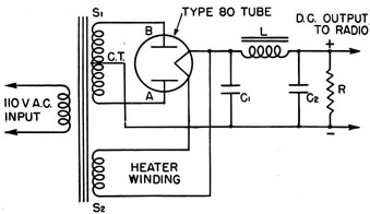
The RECTIFIER TUBE, figure 110, is a PART of a circuit
commonly called the POWER SUPPLY. In addition, the
power supply also contains a TRANSFORMER and a FILTER.
Figure 110.-Power supply.
The transformer has one primary and TWO secondary
windings, S1, and S2. Winding S1, STEPS UP and S2 STEPS
DOWN the line voltage. As an example, S1 may raise the
primary voltage from 110 to 500 volts, while S2 will reduce the primary voltage to 5 volts. The stepped UP
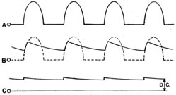
Figure 111.-Output of rectifier and filter.
150
voltage is applied to the plate of the diode, and the stepped
down voltage is used to heat the rectifier's filament.
The diode changes the a.c. into a pulsating d.c., and
that's where the FILTER comes in figure 111. The FILTER
CUTS OFF the PEAKS of the pulses and FILLS IN the GAPS
between them. While the d.c. output of the filter looks
rather bumpy in drawing B, it actually is much smoother,
more like line C. The small amount of irregularities left
in the d.c. is called the RIPPLE, which is seldom greater
than 5 percent of the output voltage.
VACUUM TUBE AMPLIFIERS
The word AMPLIFY means to INCREASE in SIZE. In
Chapter 13, you learned how one volt of grid change
produced as large a change in the plate current as 10
volts applied to the plate.
When proper resistors and condensers are correctly
connected to the vacuum tube, with the necessary voltages
applied to the circuit, an a.c. of one volt can cause an a.c.
of 10 volts to appear in the plate circuit. Thus the
vacuum tube, with its other related parts, has AMPLIFIED
the a.c. TEN TIMES.
Pulsating d.c. may also be amplified. If the voltage
applied to the grid of a vacuum tube starts at zero and
rises to a maximum of two volts, and then appears in the
plate circuit pulsating between zero and 100 volts, it has
been amplified 50 times.
A vacuum tube and its immediate related parts is
called a STAGE. The amplification of a stage is the ratio
of the voltage you put IN on the grid, to the voltage you
get OUT. Thus, if 0.5 volt a.c. is put into a stage, and 200
comes out, the amplification of the stage is-
200 / 0.5 = 400
Some times you will hear the amplification of a stage
called the GAIN of the stage.
The amplification of a stage depends upon the vacuum
tube and the condensers, coils and resistors used with the
151
vacuum tube. Some circuits using triodes have a very
small gain-two, three, or four-while others using
pentodes have gains of several hundred.
KINDS OF AMPLIFIERS
Radios use two kinds of amplifiers-AUDIO FREQUENCY
and RADIO FREQUENCY. Each is designed to do its own
work most efficiently.
Most RADIO FREQUENCY AMPLIFIERS use transformers to
couple the stages together. A pentode tube is used with
receivers and with low power stages in transmitters.
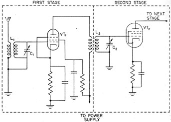
Figure 112.-Two stage r.f. amplifier.
The circuit in figure 112 is a two stage r.f. amplifier.
Transformer L1 is used to couple the antenna to the grid
of the first vacuum tube. Transformer L2 couples the
first stage to the second amplifier stage. Notice that
both vacuum tubes are pentodes.
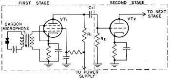
Compare the two stage AUDIO FREQUENCY AMPLIFIER of
figure 113 with the r.f. amplifier. Notice the coupling
between the stages. In the a.f. amplifier C, R1, and R2
152
form the coupling unit. This type of coupling is commonly called an R.C. COUPLING.
The input to the VT1 is from a microphone. An audio
frequency transformer T1 couples the microphone to the
grid of the tube. Notice that VT1 is a pentode and VT2 a
triode. This indicates that BOTH pentodes and triodes
are used in a.f. amplifiers.
Figure 113.-Two stage a.f. amplifier.
Figures 112 and 113 are placed in this chapter to give
you an idea of how the two kinds of amplifiers look in a
schematic diagram. You do not need to trouble yourself
to find out how they work unless you wish. It is enough
to be able to RECOGNIZE the difference when you see the
two circuits.
VOLTAGE AND POWER AMPLIFIER
Both a.f. and r.f. circuits have voltage and power amplifiers. A voltage amplifier is designed to increase the
voltage, and a power amplifier is designed to increase the
flow of current.
The FIRST stages of receivers, transmitters and audio
amplifiers, in which the input emf is weak, use VOLTAGE
amplifiers. In the output stages of all three, POWER amplifiers are used to increase the flow of current.
69919P-46-11
153
Pentodes and a few triodes are used in voltage amplifiers, while large triodes, beam power tubes, and specially
designed pentodes are used in power amplifier stages.
If you wish to learn the types of tubes and the duties
they perform, get some Electronics Technician's Mate to
explain the tubes used in the specific receiver or transmitter that you are working with.
VACUUM TUBE AS AN OSCILLATOR
Back in Chapter 11 you read that an oscillator is just a
high frequency a.c. generator, and that a COIL and CONDENSER form the oscillator. Many times you will hear it
stated that the VACUUM tube is an oscillator. That statement is not exactly correct, because NO PART of the vacuum
tube OSCILLATES. It only SUPPORTS or REINFORCES the
oscillations in the tank circuit.
A tank circuit, like the pendulum of a clock, must work
against the opposition of all resistances that surround it.
If it were not for these opposing forces, the oscillations,
once started, would continue forever.
Since neither the pendulum nor a tank circuit is perfect, each requires that ENERGY be continually added to
overcome the losses due to resistance. In the clock, a
system of springs or weights provides the energy to keep
the pendulum oscillating. In a tank circuit, a vacuum
tube supplies the energy to keep the oscillations going.
While a vacuum tube is a necessary and essential pars
of all oscillator circuits, it is NOT the part that oscillates
It merely supplies the energy.
THE VACUUM TUBE AS A DETECTOR
In order that your message may travel from transmitter to a receiver, it is necessary to combine the AUDIO
FREQUENCY SOUNDS with the RADIO FREQUENCY carries
wave at the transmitter. This combining of waves is
called MODULATION.
The MODULATED CARRIER wave is a garbled combination
of the two frequencies that cannot be heard by the human
ear. Therefore, before the message can be understood
154
the audio frequency part of the carrier wave must be
separated from the radio frequency components.
This separation of the a.f. and r.f. parts of the carrier wave is known by two names, DEMODULATION and
DETECTION.
DIODE vacuum tubes are most commonly used as detectors in Navy receivers. The tube alone does not do the
job. Additional coils, condensers and resistors are required to complete the circuits.
It is not necessary for you to know the exact action of
the detector circuits. It is sufficient if you know that the
a.f. portion of the carrier wave is sent on to the loud
speakers or earphones, while the r.f. portion is discarded
and cast aside.
OTHER USES OF VACUUM TUBES
You will find SPECIAL vacuum tubes used in a variety
of places in both transmitters and receivers. One of the
more frequent uses will be as a VOLTAGE REGULATOR.
These tubes are special diodes containing a small amount
of gas, and usually having cold cathodes.
A TUNING INDICATOR commonly called a TUNING EYE is
used in some receivers. The RBO receiver uses one of
these tubes. The purpose of the tube is to indicate the
PRESENCE of a station, and also to indicate when the receiver is correctly tuned.