The place to cure a pain-such as interelectrode capacitance-is at its source. Since the source of interelectrode
capacitance is in the tube, the tube is the place to work
the cure.
This is done by putting a SECOND grid between the first
grid and the plate. Both grids are alike in design. To
prevent confusion, call the original grid the CONTROL
GRID, and this new grid the SCREEN GRID. The new tube
is called a TETRODE. The SCREEN GRID is connected to a
positive potential that is usually lower than the plate
potential.
SWAPPING TROUBLES
The tetrode cures the trouble you had with interelectrode capacitance in the triode. BUT you run into a
new trouble with the tetrode-since the screen grid is
139
positive, it will attract some electrons and keep them
from getting to the plate.
But what is more serious-the electrons that do arrive
at the plate will be traveling at a velocity high enough to
KNOCK OTHER ELECTRONS LOOSE FROM THE METAL OF THE
PLATE. The process of "knocking" other electrons off
the plate is called SECONDARY EMISSION. These electrons
will form another space charge between the plate and
screen. Now, if the screen is at a potential equal to or
greater than the plate potential, the electrons of the space
charge will flow to the screen, further reducing the NUMBER that reach the plate.
WHAT IS WRONG WITH THE TETRODE?
The output of a tetrode has a tendency to make the
music sound CORNY. The voice of your favorite blues
singer would sound like a bull-frog with a cold. This is
DISTORTION. You want amplifiers to put out exactly the
SAME SOUNDS that are put in. You want the signal amplified, but you don't want any hash added to it.
The tetrode was used extensively. If you watched
your operating potentials, the distortion could be kept to
a minimum. Today, this tube has been largely replaced
by a much improved type known as the PENTODE.
THE PENTODE
The secondary emission of the tetrode was responsible
for the development of this new tube. Since the effect
of the secondary emission is largely that of robbing the
plate of its electrons, the search naturally turned to
finding a way of either preventing or reducing this
effect. The outcome is a new tube, with ANOTHER GRID
placed between the screen grid and the plate.
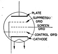
The new element is the SUPPRESSOR GRID, or just SUPPRESSOR. Observe in figure 107 that it is connected directly to the cathode. Thus, whatever potential is placed
upon the cathode is ALSO PLACED ON THE SUPPRESSOR.
In some pentodes, the connection to the cathode is made
internally-that is, the cathode and suppressor are
140
Figure 107.-Schematic symbol of a pentode.
connected together INSIDE THE GLASS ENVELOPE OF THE TUBE.
In other pentodes, the suppressor connection is brought
outside to a pin connection in the base of the tube. In
this case it is necessary to make the connection to the
cathode EXTERNALLY.
HOW THE PENTODE REDUCES THE EFFECT OF
SECONDARY EMISSION
The way the suppressor grid reduces the effect of secondary emission from the plate can be understood by
examining figure 108.
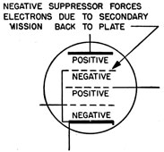
Figure 108.-Relative potentials in a pentode.
141
The most positive element in a vacuum tube is the
plate. In a pentode, the next most positive is the screen
grid. The most NEGATIVE element is the grid. Since
the suppressor is connected to the cathode, these two
elements are EQUALLY NEGATIVE.
Notice, in figure 108, that before any electrons of the
secondary emission from the plate could get to the screen
grid, they'd first have to pass the NEGATIVE SUPPRESSOR.
But that's impossible-the NEGATIVE CHARGE on the suppressor drives all of these electrons BACK TO THE PLATE.
In this way, the suppressor grid prevents the electrons
of secondary emission from reaching the screen.
AMPLIFICATION OF TRIODES AND PENTODES
The amplification factor for this pentode is about 60
times as great as it is for the triode. For example-if
one volt of a.c. were placed on the grid of each tube, the
triode would produce an a.c. voltage change in the plate
circuit of only 20 volts. But with the same grid voltage
the pentode would produce a plate voltage change of 1,200
volts. In practice these values are not easily attained,
but in theory it is possible. Here's the important thing-with
a pentode, you can START WITH LESS AND FINISH
WITH MORE.
INTERELECTRODE CAPACITANCE
TRIODES VS PENTODES
You already know that the interelectrode capacitance
of a pentode is much less than that of a triode. Usually
the plate-grid capacitance of a pentode is about 1/1000 that
of a similar triode. For example, compare this capacitance for the 6J5 and 6J7 tubes-
Triode-6J5--4.000μμf.
Pentode-6J7--0.005μμf.
These examples are representative of most triodes and
pentodes.
142
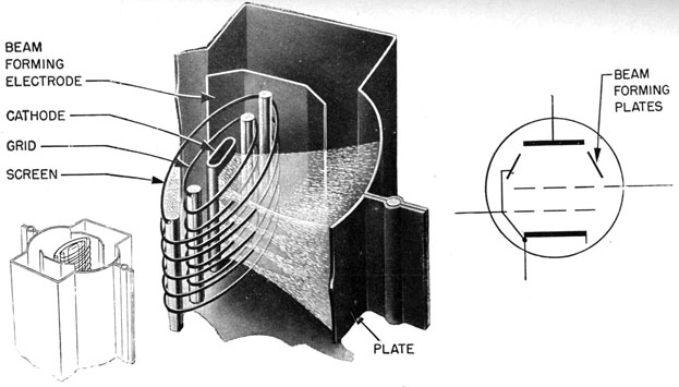
Figure 109.-Beam power tube
143
BEAM POWER TUBE
The BEAM POWER TUBE is a new design that combines
many of the advantages of the triode and pentode.
Whether this tube is a tetrode or a pentode depends entirely upon your definition of what constitutes a tetrode
and a pentode. Actually, it is neither a tetrode nor a
pentode-better call it a BEAM POWER TUBE.
In figure 109 you'll see that this tube has a cathode, a
control grid, a screen grid, and a plate. In addition to
these parts, it also has TWO BEAM-FORMING PLATES. Each
beam-forming plate extends about one-fourth the distance
around the grids of the tube. The remaining distance
is open The plates are connected to the cathode, and
therefore they operate at the cathode potential.
The openings in the grids are arranged in such a manner as to cause the electrons to form into LAYERS or
SHEETS as they pass between the windings on their way
to the plates. After passing the screen grid, the sheets
of electrons combine to form a BEAM.
In this tube, the SCREEN POTENTIAL is made GREATER
than the plate potential so that the electrons arriving at
the plate will be moving from a HIGHER to a LOWER
potential. Their speed will be reduced in a manner similar to that of an automobile coasting up hill.
Because the electrons that reach the plate are traveling
at a lower speed, FEWER ELECTRONS WILL BE KNOCKED
OFF THE PLATE. Those secondary electrons that do
bounce off the plate are caught in the BEAM and swept
back to the plate.
The beam-forming plates prevent stray electrons from
returning to the screen grid, and the plates also SHAPE
the electron beam. The combined action of the plates
and grids reduces the screen current to a low value.
The beam power tube has two major advantages-it
is as sensitive as most pentodes, and it can handle large
currents. These two advantages allow you to CONTROL
LARGE UNITS OF POWER WITH A SMALL AMOUNT OF GRID
ENERGY
144
This feature will be clear to you when you discover the
large number of places beam tubes, such as the 6L6, are
used to regulate fire control equipment.
TRANSMITTING TUBES
You have seen pictures of TRANSMITTING TUBES that are
as tall as a man, and still others of queer shapes and
designs. In spite of their size and shape, they are only
diodes, triodes, tetrodes, and pentodes, basically like those
you have studied.
Transmitting tubes have to be large since many of
them must be able to deliver SEVERAL THOUSAND WATTS
of power. In comparison, most receiving tubes cannot
carry more than two or three watts. Just as the airplane
engine of several thousand horsepower is larger than the
automobile engine of 100 horsepower, the transmitting
tube must be LARGER AND STRONGER than the receiving
tubes.
First of all, the transmitting tubes must be able to
dissipate or get rid of large amounts of heat. To do this,
the plate, grids, and cathode are made LARGER AND
HEAVIER, and the tubes are provided with a cooling system. Some transmitting tubes are cooled by circulating
water, but most of them have a forced draft of air circulating around them. Few water-cooled tubes will be
found in Navy equipment.
One of the most common causes of failure in transmitting tubes is overheating due either to faulty cooling
or to overload. A tube that operates at a dull cherry
red is near the danger point. Any slight additional heat
may damage the tube. Check the fans and other cooling
systems to see that they are operating properly.
As strange as it may seem, most metals have a small
amount of some inert gas-nitrogen or argon-dissolved
in the metal of the plate. If the plate becomes red hot,
this gas will escape from the metal and float around
inside the vacuum tube. This gas is objectionable because it prevents the grid from exercising the proper
control of the electrons going to the plate. If this
145
happens, a faint blue glow will appear between the cathode
and the plate. When you get a gassy tube, replace it.
BUT-
First check to be sure that the gassy tube you are
replacing is not one that is SUPPOSED to have this blue glow.
Remember, mercury vapor tubes are designed with gas in
them and give off a similar bluish glow.
MORE INFORMATION, PLEASE?
So far, you have met only a representative few of the
many dozen different vacuum tubes in everyday use. A
great number of tubes are similar to these few, and others
are identical both in structure and in electrical characteristics. You'll be working with many different tubes,
but you are not expected to remember all their different
characteristics. The information can be found quickly
in any STANDARD TUBE MANUAL, which the chief will have
on his book-shelf.
WHAT'S IN A TUBE MANUAL
In addition to dope on AMPLIFICATION FACTORS, PLATE
RESISTANCE, TRANSCONDUCTANCE, and INTERELECTRODE
CAPACITANCE, you will also find the following information
MAXIMUM PLATE VOLTAGE and MAXIMUM PLATE current-as the names indicate, these are the MAXIMUM
permissible values of current and voltage that can be
used without damage to the tube.
TYPICAL OPERATING CHARACTERISTICS-A vacuum
tube is seldom operated at its maximum rated values.
The TYPICAL values are those you will be likely to use
in an ordinary circuit to obtain best results and longer
tube life.
USES FOR THE TUBE-This section tells you that the
manufacturer recommends the tube for use in one or
more of these spots-
146
R.F. AMPLIFIER
A.F. AMPLIFIER
POWER AMPLIFIER
DETECTOR
RECTIFIER
FILAMENT VOLTAGE and FILAMENT CURRENT-this
information is important. If the tube has insufficient
filament voltage, it will not operate at top efficiency.
But a voltage that is too high will burn it out. When
you are installing or replacing a tube, be sure that the
filament voltage is correct. The numerals in front of
the letter in the tube number give you the APPROXIMATE
filament voltage.
In the 1A5, the ONE means 1.4 filament volts.
In the 2A3, the TWO means 2.5 filament volts.
In the 5U4, the FIVE means 5.0 filament volts.
In the 6L7, the SIX means 6.3 filament volts.
In the 12K7, the 12 means 12.0 filament volts.
In the 35Z5, the 35 means 35.0 filament volts.
In the 117L7, the 117 means 117.0 filament volts.
POWER RATING-Tubes designed as POWER TUBES will
have their MAXIMUM SAFE POWER-HANDLING capacity
in WATTS.
SOCKET CONNECTION-tube bases are fitted with KEYS
and PINS so that you can put a tube in the socket in
only the RIGHT position. Tube manuals give you the
socket connections for each tube. Most tubes fit into
an EIGHT-PIN SOCKET. The pins are numbered CLOCKWISE as you view the connections from the BOTTOM, the
numbering starting at the KEY SLOT.