All of us at one time or another have solved problems in relative motion,
probably without
recognizing them as such. Crossing a busy street safely, intercepting the
player carrying the
ball in a football game, running to catch a ball, all of these activities
involve a problem in
relative motion, even though we do not realize it. In a more complex
form, all combat tactics,
their determination and execution, deal with relative motion; that which
is seen on the radar's
PPI scope is relative motion. Hence, it is necessary that all personnel
attached to the Combat
Information Center, from the operator to the Captain, have a thorough
understanding of the
varied applications of this important principle.
The basic method of solution of relative motion problems utilizes the
maneuvering board, and it
is therefore required that all personnel should be capable of using it
and applying its solutions.
What is meant by relative motion? It is the resultant of two actual
motions, but let us break
this down further. The word motion implies direction, speed, and
distance; relative motion,
then, would
imply relative direction, relative speed, and relative distance, which are
defined as follows:
Relative direction is the apparent direction of one object's movement
with reference to another.
Relative speed is the speed with which one object moves with respect to
another.
Relative distance is the distance one object moves with respect to
another.
These three definitions then, collectively make up relative motion.
Realizing that relative motion is caused by two actual movements, let us
analyze the movement
of two objects within the same vicinity. Since we are concerned
principally with relative
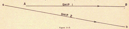
motion as applied to moving ships, imagine two ships in the positions
shown in figure 5-2,
moving in a general easterly course, during a period of 20 minutes.
The initial position of Ship 1 is at the point A. Moving on a due
easterly course it arrives at point
B 20 minutes later. Picture Ship 2, starting from initial position a,
which is 2,000 yards
astern of Ship 1, and arriving 20 minutes later at position b, 2,000
yards broad on the
starboard beam of Ship 1.
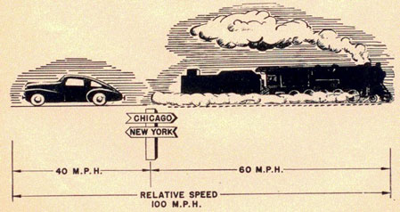
Figure 5-1.
5-2
RELATIVE MOTION
Figure 5-2
Analyzing the original definition of relative motion, it is obvious that
these two motions establish a
relative motion. If you establish a relative plot of one object with
reference to the other, you
should be able to ascertain that relative motion. Now, picture yourself
on Ship 1, and try to picture what movement Ship 2
would make with reference to you in that 20 minutes.
If you (on Ship 1) are moving due east, and Ship 2
is at a position 2,000 yards astern, its initial position would be 270 degrees T
at 2,000 yards, at
time 00. Ship 2's position after 20 minutes, with reference to you (Ship
1), would be 180 degrees T at 2,000 yards. To establish or form a relative plot, you merely plot
successive positions of an
object from a stationary point, which represents your position at all
times, regardless of the
fact that you are moving.
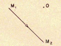
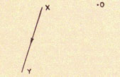
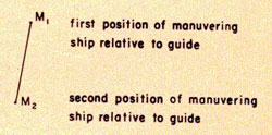
Figure 5-3.
Point O, figure 5-3, represents your position at
all times, point M1, the relative position of Ship 2
at time 00, and point M2, is the relative position of Ship 2 after 20
minutes. By drawing the
line from M1 to M2 you establish an imaginary line that indicates the
apparent movement of
Ship 2 with reference to yourself; therefore, the direction of the line
from M1 to M2 would
indicate the direction of relative movement. The length, or distance, of
the line would indicate,
according to definition, the distance of relative motion during a period
of 20 minutes.
If the distance from M1 to O or M2 to O is to represent 2,000 yards, you
can measure M1M2 using the same scale, and find it to be about 2,800 yards.
Using the formula: distance divided by time equals speed, you have:
speed = distance/time
speed = 2800/200
speed = 140 yards per minute
Multiply yards per minute by 0.03 and you have miles per hour, or knots.
speed = 140 x 0.03
= 4.2 miles per hour.
Therefore, the speed of relative motion would be 4.2 knots.
Examining the direction of the line M1M2 you find it to be 135 degrees T.
Listing of the
information found from the relative plot you have the following:
Direction of relative motion, 135 degrees T
Distance of relative motion, 2,800 yards
Speed of relative motion, 4.2 knots.
You have, therefore, found the three parts of relative motion from the
relative plot.
Leaving the relative plot, let us analyze a second method of determining
relative motion, which
is called the vector diagram. The vector diagram is a picture in which we
combine the
movements of two objects, with respect to a third object, to find their
movement with respect to
each other. The third object is usually the earth, so that we are really
combining two
geographical movements to find relative motion. To show these movements,
geographical or
relative, as pictures, we use single lines, called vectors. The slope or
direction of the vector
indicates the direction of the movement it portrays; the length of the
vector indicates the speed
of the movement. By properly combining two vectors, showing how two
objects are moving with
respect to the earth, and then drawing the resulting vector necessary to
complete a triangle, the
resultant side will be the relative movement of the two objects involved.
Let us see why that
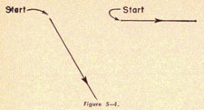
resultant does actually establish the relative motion. Let us suppose you
have two objects, the
first, moving on a course of 090 degrees at a speed of 12 knots, and the second,
in the same vicinity,
moving on a course of 150 degrees at a speed of 15 knots, as shown in figure 5-4.
5-3
RADAR OPERATOR'S MANUAL
Figure 5-4.
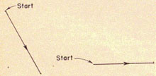
If you should form a relative plot of these two moving objects for a
full hour, as shown in
figure 5-5, you would get the line XY.
Figure 5-5
From what you know of the relative plot, you realize that the direction of XY, is the direction of the relative motion; the length of XY, is the distance of relative motion; and the time interval in this case is one hour.
But what is the distance per hour? It is speed. Therefore, the length XY, is the speed of relative motion. Suppose you move the position of the second ship so that it moves from some other position with the reference to Ship 1, but remains on the same course and at the same speed, as shown in figure 5-6.
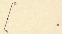
Figure 5-6.
Figure 5-7 is made by forming the relative plot of figure 5-6 and we get the line X1Y1.
By the same deductions as used in figure 5-5, we find the direction of relative motion and the distance of relative motion in one hour, which is the speed of relative motion. By comparison, we find that X1Y1 is the same direction and represents the
Figure 5-7.
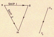
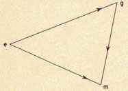
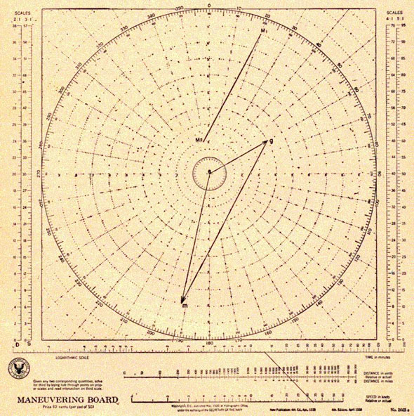
same speed as XY. So, let us start Ship 1 and Ship 2 on the same courses and speeds as before, but from a common point, as shown in figure 5-8.
Figure 5-8.
If you establish the relative plot, you find that X2Y2 is in the same direction as XY and X1Y1 and the same length as XY and X1Y1. Likewise, if you connect the terminal positions of Ship 1 and Ship 2 (points g and m) you find that the line is also in the same direction and the same length as XY and X1Y1. Therefore, it appears unnecessary to form the relative plot, when course and the speeds of two moving objects are known. Instead, you can draw two lines which indicate direction and speed, that is, draw two vectors from a common point; then by connecting the ends of those vectors you will find the resulting vector, which represents the direction and speed of relative motion. This triangle, which is called the vector diagram, and labeled egm, as shown in figure 5-8, is the solution of two actual motions, namely eg and em, which produces the resultant gm. This resultant is the direction and
5-4
RELATIVE MOTION
speed of relative motion. At this point, let us sum up what is
represented by the various vectors
of the vector diagram, egm.
eg represents the course and speed of the unit to which the relative
motion is referred, or the
guides course and speed. The course being indicated by the direction of
eg, and the speed being
indicated by the length of eg.
em represents the course and speed of the second moving object, or the
maneuvering unit's
course and speed, the course being indicated
by the direction of em, and the speed being indicated by the length of
em.
gm represents the
relative motion with reference to the guide ship, that is, the direction
from g to m represents
the direction of relative motion, and the length of gm indicates the
speed of relative motion.
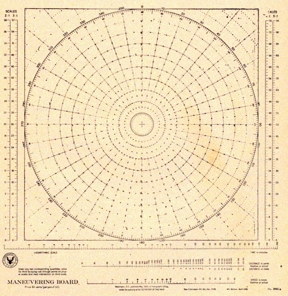
USING THE MANEUVERING BOARD
Figure 5-9 is a standard Navy maneuvering board. Notice that it is a
polar coordinate system,
Figure 5-9.
5-5
RADAR OPERATOR'S MANUAL
that is, divided into 360 units or degrees. This will enable you to
establish or indicate any
direction whatsoever, in degrees, on a true basis. The outer numbers
indicate the true
direction, whereas the inner numbers will indicate the opposite, or
reciprocal direction.
The maneuvering board is made up of ten concentric circles, that is, ten
circles having the same
center. You can therefore indicate any speed or distance desired, by
choosing the proper scale. If
a 1/1 scale is chosen, you can indicate any speed from 1 to 10 knots. If
you choose a 2/1 scale,
you can indicate speeds up to 20 knots. etc.
Figure 5-10.
In representing distances, use scales such as 1 unit
is equal to 2,000 yards, or 1 unit is equal to 3,000
yards, etc.
The scales on the left and right of the board, that is 2:1, 3:1, 4:1, and
5:1, are simply aids to be
used in computation in accordance with whatever scale is chosen.
The logarithmic scales, at the bottom of the chart, that indicate time,
distance, and speed, are so
placed as to enable you to solve problems of time, distance, and speed,
merely by drawing a
straight line. For example, if you know that an object has traveled 3
miles in 10 minutes, you
can place a point on the distance scale at the position that indicates 3
miles, and on the time
scale at the position that indicates 10 minutes. By drawing a line
through those points and
extending it until it intersects the speed scale, you will find that it
crosses the speed scale at 20
knots. That is, the object is traveling at a speed of 20 knots.
Obviously, the care with which you
establish your points and draw your line has a direct bearing on its
accuracy.
It must be realized, that if you use time and relative distance, or
relative speed, the result will
be relative speed or relative distance. Likewise, if you use actual
distance, or actual speed with
time, the result will represent actual speed or actual distance.
If you are requested to draw the vector diagram egm on a maneuvering
board, obviously, the
simplest procedure is to place one of the angles of the triangle at the
center of the chart. For the
sake of consistency, let us say that we will always place point e at the
center of the chart. This
point e has no meaning by itself; it is merely the point at which two
vectors are joined. It is
absolutely incorrect to think of the guide as moving from e to g during
the maneuver; he does
not. The line eg shows the direction and speed of the guides movement
over the earth; it in no
way indicates his starting point or final position. Naturally, whatever
scale is used to represent
the speed of the guide, must be consistently used in the representation
and interpretation of eg,
em, and gm. Going back to the relative plot, you realize that you have established the position of
M1 and M2 with
reference to the guide's position, ignoring the movement of the guide, it
would be possible to
draw this relative plot on the same maneuvering board, even though the
relative plot and the
vector diagram are two different problems. Since they are different
problems, it is possible to
use a scale in the relative plot different from that which was used in
the vector diagram. In
order to keep in mind which scale you are using for egm (the vector
diagram) and which for the
relative plot, it will be helpful to label the scales. In the
illustrations, notice that the distance
scale is marked D and the speed scale is marked S.
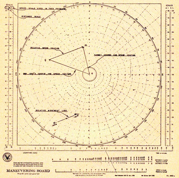
Examining figure 5-10, which is a relative plot and a vector diagram,
notice that the line gm is
parallel gm represented the direction of relative motion. It to the line
M1M2. It has been
shown that the line
5-6
RELATIVE MOTION
has also been shown, that M1M2, represents the direction of relative motion. If both lines are to
represent the same direction, it is obvious that they must be parallel.
In geometry if you have two sides and the included angle of a triangle,
you are able to establish
the third side. That is, if you know the direction of two sides of a
triangle and the length of those
sides, it is an easy matter to find the third side. Therefore, knowing eg
and em, gm can be found
by connecting the points g and m. Likewise, if you know eg and
the direction and length of gm, it is simple to find em.
In cruising at sea, you should always know or be able to find one line of
the vector diagram,
since you always know your own course and speed. You could establish or
start a vector diagram
by drawing the line eg to represent your course and speed, choosing an
appropriate scale in
accordance with the speed. If you pick up a contact bearing 280 degrees at
24,000 yards, you could
establish point M1, and report a contact at that position with reference
to your ship.
Figure 5-11.
5-7
RADAR OPERATOR'S MANUAL
Now that you have found the contact before getting too close, the next
step is to establish exactly
what the contact is doing, or in terms of the diagram, the length and
direction of the line em.
How can that be determined? If the relative motion between your own ship
and the contact is
known, you can draw the line gm and therefore establish the line em.
Then you can report what
the contact is doing. How can you find the relative motion? Having
established a relative plot,
you can find M1M2, which tells all you need to know about relative
motion. You recall, that to
form the relative plot, you need to know a series of successive positions
of the contact with
respect to your ship. Where can you get this information? The answer is
the radar. The radar
tells where the unit is with reference to your ship, so you can establish
in a short period of
time a relative movement line M1M2 (M2 being a later relative position
than M1). Thus,
M1M2 forms the relative plot. Let us say that M1M2 is the
direction of relative motion.
Therefore, you are able to draw the line from g parallel and in the same
direction as M1M2.
Since the length of gm is determined by the speed of relative motion,
you must next find the
speed of relative motion. By measuring M1M2. which gives the distance of
relative motion, and applying that distance and elapsed time between M1, and
M2, in the formula D=RT,
you find the speed of relative motion. Using the same scale that was
chosen when eg was
established, lay off the distance from g to m, making it equal to the
speed of relative motion.
This established the point m. By drawing the line from e to m you can
tell the course of the
contact by the direction of em. The length of em, according to the
established scale, represents
the speed of the contact. The information is now ready to be reported,
and together with the
operator's interpretation of the composition, will enable the proper
decision to be made in
regard to combatant tactics.
ILLUSTRATED EXAMPLES
Finding course and speed of the maneuvering ship.
Suppose you are cruising along on a course of 290 degrees, at a speed of 18
knots. At 1506 you pick up
a contact at a bearing of 213 degrees and at a range of 16,000 yards At 15152
the contact has moved to
a position of 200 degrees, 12,400 yards away from you. Your problem is to find
the contact's course
and speed.
Procedure
Reason for Procedure
1. Choose a scale of 3 knots = 1 unit, to establish the vector diagram.
1. Make the egm triangle as large as possible to insure greater accuracy of measurement. Using 3:1 scale you can represent speed up to 30 knots.
2. Draw eg on 290 degree line and 6 units in length.
2. eg represents your own course and speed which is 290 degrees at 18 knots. 18 / 3=6 (3:1 scale).
3. Choose a scale of 2,000 yards = 1 unit, for the scale of relative plot.
3. Again you want the largest scale possible for accuracy. A scale of 2,000 yards = 1 unit will allow you to plot points within 20,000 yards on your board.
4. Plot M1 at 213 degrees at 8 units from e. Label and time.
4. The contact was at 213 degrees at 16,000 yards from you at 1506. Your position is considered to be at the center at all times. 16,000 / 2,000 = 8 (2,000:1 scale).
5. Plot M2 at 200 degrees at 6.2 units from e. Label and time.
5. The contact was at 200 degrees at 12,400 yards from you at 15152. 12,400/2,000=6.2.
6. Draw M1M2.
6. M1M2 represents the direction of relative motion.
7. Draw a line from g parallel to and in the same direction as M1M2.
7. The line from g to m is also the direction of relative motion, so gm is parallel to M1M2.
8. Measure M1M2, and find the distance of relative motion, using 2,000 yards to 1 unit scale. Distance of relative motion 4,800 yards.
8. To find where m falls on the line from g, recall that the length of gm is determined by the speed of relative motion. To find relative speed, solve relative distance with time in the formula D = RT (D = distance, R = speed, T = time).
5-8
RELATIVE MOTION
Procedure
Reason for Procedure
9. Time interval of relative plot is 9 1/2 minutes.
9. 15152 - 1506 = 9 1/2 minutes.
10. Speed of relative motion is 15 1/4 knots.
10. Using 4,800 yards distance of relative motion and time 9 1/2 minutes, according to instructions, the line crosses speed scale at 15 1/4 knots.
11. Lay off gm 15 1/4 knots. (3:1 scale).
11. gm represents the speed of relative motion by its length. 3:1 scale was established in Step 1 for vector diagram.
12. Draw em.
12. The two points fix the line em.
13. Course of contact is 347 degrees.
13. Direction of em gives course of maneuvering unit.
14. Measure em of 3:1 scale. Contact's speed is 12 knots.
14. Length of em furnishes speed of maneuvering unit.
The foregoing problem furnishes a means of determining the course and
speed of a radar contact;
We must realize, however, that this method has limitations and for this
reason often may not be
the best and simplest solution. Sometimes it is the only means available,
unfortunately, and we
should, therefore, master it thoroughly.
Let us consider some of the disadvantages of figuring course and speed of
a radar contact by this
method. For one thing, the solution is correct only when our ship remains
on a steady course and
speed throughout the period of time used to form the relative plot.
Furthermore, if the relative
speed is slow, it requires a greater period of time to establish a
relative plot that is large
enough to measure with any degree of accuracy. In forming a relative
plot, a change of speed is
not easily detected. This increases the possibility of error in the
solution of the contact's speed.
If there is a DRT (Dead Reckoning Tracer) available, it will furnish
information more quickly
than a maneuvering board in this problem. It is a good idea, however, to
check the DRT solution
by the maneuvering board when possible, to see that the mechanics of the
DRT are functioning
correctly.
Maneuvering to attack position.
Suppose you have picked up a contact and have
determined that it is traveling on a course of 060 degrees
at a speed of 12 knots. The contact bears 200 degrees, at a range of 18,000
yards from your ship.
Your task is to figure out a course to maneuver your ship to an attacking
position, 70 degrees off the
port bow, at a range of 4,000 yards, using a speed of 24 knots, and the
time that will be
required to accomplish this maneuver.
Procedure
Reason for Procedure
1. Choose the scale of 3:1 for vector diagram.
1. Since you must represent speeds of 24 knots and 12 knots you will use a 3:1 scale, because it is the largest scale possible in this case.
2. Draw eg on a course of 060 degrees four units long. (3:1 scale).
2. Since you are to make the maneuver, you will he the maneuvering ship, therefore, the contact will have to be the guide. Contact's course is 060 degrees, speed is 12 knots 12 / 3 = 4 (3:1 scale).
3. Choose the scale of 2,000:1 for relative plot. Plot M1 at 020 degrees, nine units from e.
3. If the contact bears 200 degrees from your ship, you obviously bear 020 degrees from him, He is now guide, so you use 020 degrees. Scale 2,000:1 is the largest scale capable of representing 18,000 yards. 18,000 / 2,000 = 9.
4. Using the 2,000:1 scale, plot M2 at 350 degrees, two units from e.
4. If the contact is on course 060 degrees and you desire to be 70 degrees on his port bow: 060 degrees - 70 degrees = 350 degrees. 4,000 / 2,000 = 2.
5-9
RADAR OPERATOR'S MANUAL
Procedure
Procedure
5. Draw M1M2.
5. M1M2 gives the direction of relative motion and the distance of relative motion.
6. Draw a line from g parallel to M1M2 and in the same direction as M1M2.
6. The line from g to m will represent the direction of relative motion. It is therefore, parallel to and in the same direction as M1M2.
7. Where the line from g intersects the 8th circle, label m.
7. You know that m must fall somewhere on the line from g. Since you are the maneuvering unit, and your speed is to be 24 knots, the line em must be 24 knots long, or 8 units long, using
Figure 5-12.
5-10
RELATIVE MOTION
Procedure
Reason for Procedure
a 3:1 scale. The point at which the 8th circle crosses the line from g is the only one that satisfies both conditions.
8. Draw em, your course and speed. That is 192 degrees at 24 knots.
8. em is the maneuvering unit's course and speed.
9. Find the distance of relative motion by measuring M1M2, or 2,000:1 scale. Distance relative motion, 14,600 yards.
9. M1M2 represents the distance of relative motion and is 7.3 units long. 7.3 x 2,000 = 14,600.
10. Find the speed of relative motion by measuring gm on 3:1 scale. Speed of relative motion is 33.3 knots.
10. gm represents the speed of relative motion and is 11.1 units long. 3 x 11.1 = 33.3.
11. Time required to make maneuver is 13 minutes.
11. Continuing your solution at the bottom of the chart you find that the line determined by the points of 14,600 yards on the distance scale, and 33.3 knots on the speed scale, crosses the time line at 13 minutes if extended.
The preceding maneuvering problem and variations of that problem are the
most frequently
used in CIC operations. Ships moving in company often are ordered to make
certain maneuvers
within the force for various purposes, such as refueling, searching
areas, changing station, or
allowing aircraft carriers to launch planes. Placing attacking ships in
the best strategic
position to engage the enemy forces, also requires this type of a
solution.
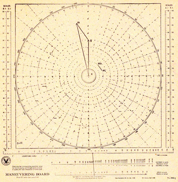
Simple torpedo problem.
Assume you are on the necessary course and traveling at the proper speed
to arrive at a position
5,000 yards and 60 degrees off the starboard bow of an enemy vessel, which has
been determined to be
on a course of 163 degrees at a speed of 15 knots.
Upon arriving at that position, your ship is to fire a 27-knot torpedo at
the enemy ship. What course should the torpedo be set on?
Procedure
Reason for Procedure
1. Draw eg in the direction of 163 degrees and 5 units long, using 3:1 scale for speed.
1. The torpedo will have the role of the maneuvering unit. The enemy ship is considered as the guide. His course is 163 degrees; his speed is 15 knots. 15 / 3 = 5 units.
2. Establish M1, at point 223 degrees and 5 units from e using 1000:1 scale.
2. Your firing position is 60 degrees off the starboard bow of the enemy at a range of 5,000 yards. 163 degrees + 60 degrees = 223 degrees; 5,000 / 1,000 = 5.
3. Establish M2 at the center.
3. You want the torpedo to hit the enemy, at the center in relation to your ship.
4. Draw a line from g in the direction established by M1 to M2.
4. M1M2 is the direction of relative motion and gm also the direction of relative motion. Point m must also be on that line.
5. Where the line from g intersects the 9th circle place point m; draw em, the torpedo's course and speed.
5. You know em must be 9 units long to represent 27 knots, the speed of your torpedo. The point of intersection is the only point on the line from g which satisfies that condition.
6. Torpedo course is 072 degrees, speed 27 knots.
6. em represents the maneuvering unit's course and speed.
5-11
RADAR OPERATOR'S MANUAL
Figure 5-13.
Station keeping.
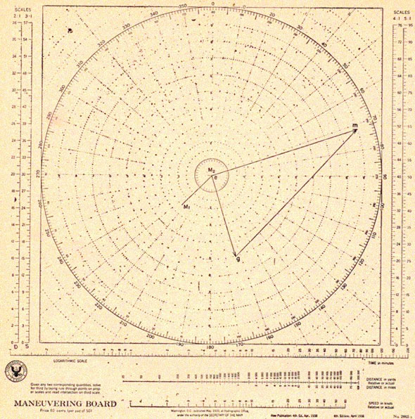
A convoy is on a base course of 030 degrees at 10 knots. Your position is 40 degrees relative, at a range of 2,000 yards from the guide. At 1400, guide makes an
emergency turn to 000 degrees course. You are to use 15 knots to return to station. What course do you take? At what time will you be back on station?
Procedure
Reason for Procedure
1. Draw eg on 000 degrees, 5 units in length, 2:1 scale.
1. As long as guide is on course 030 degrees, you are on station, but when he turns to 000 degrees you are out of position and must return to proper station. Guide's speed is 10. 10 / 2 = 5 (2:1 scale).
2. Establish M1 at 070 degrees, 2 units from e. (1,000:1 scale).
2. Your position was 40 degrees beyond original course of 030 degrees at a range of 2,000 yards. 2,000 / 1,000 = 2.
5-12
RELATIVE MOTION
Figure 5-14.
Procedure
Reason for Procedure
3. Establish M2, at 040 degrees, 2 units from e.
3. When guide comes to course 000 degrees you wish to come to a position 40 degrees from the guide at a range of 2,000 yards. 2,000 / 1,000 = 2.
4. Draw M1M2, in the direction of relative motion.
4. M1M2 determines the direction of relative motion.
5. From g draw a line parallel to and in the same direction as M1M2.
5. g to m is also the direction of relative motion and in must be on that line from g.
6. Where the line from g crosses the circle, 7 1/2 units from e, establish point m and draw em.
6. em must be 7 1/2 units long as your own (the maneuvering unit's) speed is to be 15 knots for the maneuver. 15 / 2 = 7 1/2. (2:1 scale).
5-13
RADAR OPERATOR'S MANUAL
Procedure
Reason for Procedure
7. Required course is 347 degrees speed 15 knots.
7. em is in direction of 347 degrees and 7 1/2 units long.
8. Measure the length of M1M2 on the 2,000:1 scale. Relative distance is 1,050 yards.
8. M1M2 is the distance of relative motion and is 1,050 yards in length. (2,000:1 scale).
9. Measure gm on 2:1 scale; speed of relative motion is 5.7 knots.
9. gm is the speed of relative motion, and is 5.7 knots in length. (2:1 scale).
10. Solving on the scales at the bottom of the chart, we find the time required to return to station is 5 1/4 minutes.
10. Relative distance divided by relative speed results in time.
PRACTICE PROBLEMS
The following problems of average difficulty are for
practice in use of the maneuvering board.
1. You are traveling on course 120 degrees at 16 knots. At 0405 you pick up a
contact at 236 degrees, range 16,000 yards. At 0411 the contact bears 239 degrees at 19,000 yards. What is the course and speed of the contact?
ans. 187 degrees-12 knots
2. Your ship is on course 070 degrees at a speed of 18 knots. At 0316 there is a
contact at 050 degrees, range
18,000 yards. After tracking the contact for 9 minutes, he then bears 058 degrees at 13,000 yards.
REQUIRED:
(a) What is the contact's course and speed?
(b) Contact's course and speed at 0328?
(c) What range will he be on when he crosses dead ahead of you?
ans. (a) 142 degrees-12 1/4 knots
ans. (b) 062 degrees-11,400
ans. (c) 9,500
3. A freighter is traveling on a course of 025 degrees at a speed of 10 knots,
An enemy destroyer is on
a course 115 degrees at a speed of 20 knots. Visibility is 6,000 yards. The
destroyer bears 300 degrees at a range of 15,000 yards at 0115.
REQUIRED:
(a) If both ships remain on their present course and speed,
would an alert lookout be able to sight the enemy?
(b) If so during what interval of time?
ans. (a) Yes
ans. (b) Between 0130 and 0137
4. Your ship is traveling at 16 knots. On a course 325 degrees with an
escort 2,000 yards dead ahead. At midnight the escort picks up a contact
at 291 degrees, 15,200 yards from him and reports it. Five minutes later you find the contact bears 283 degrees, 14,800 yards.
REQUIRED:
(a) What is the contact's course and speed?
(b) Assuming no change in courses and speeds, and on the basis of your
initial contact, what
time would you lose the contact from your radar screen?
ans. (a) 201 degrees-10 knots
ans. (b) 0021
5. You have determined that a contact is on course 138 degrees at a speed of 17 knots. You are now approaching a point 60 degrees off the port how at a range of 5,000 yards in order to fire a 36-knot torpedo at the contact.
REQUIRED:
(a) On what course should the torpedo be set?
(b) How far will the torpedo run?
ans. (a) 234 degrees
ans. (b) 4,300 yards
6. You have found an enemy transport which is traveling on a course of 235 degrees at a speed of 14 knots. You wish to use a speed of 24 knots to maneuver into a position 70 degrees off the nearest bow at a range of 6,000 yards. At the time of the start of the maneuver the enemy bears 116 degrees, range 16,200 yards.
REQUIRED:
(a) What course will you use?
(b) What is the length of time of the run?
ans. (a) 139 degrees
ans. (b) 11 minutes
7. A convoy is traveling on a course of 255 degrees at a speed of 12 knots. You
wish to take it under
fire from a position broad on the beam, from a range of 10,000 yards. At
present it bears 150 degrees, 18,000 yards.
REQUIRED:
(a) What is the slowest speed you can use in this maneuver?
(b) What speed would you use to maneuver if you chose a course of 170 degrees?
ans. (a) 10.2 knots ans.
ans. (b) 16.6 knots
8. You are stationed 060 degrees relative to the guide, at a
range of 6,000 yards. Base course is 300 degrees, speed 11
5-14
COMBAT INFORMATION CENTER
knots. An emergency turn 90 degrees to starboard is executed at 0315.
REQUIRED:
(a) If you use a speed of 20 knots, what course shall you take to return to your station?
(b) At what time will you arrive on station?
ans. (a) 103 degrees
ans. (h) 0328
9. You have a contact south of you on a course of 080 degrees at a speed of 14
knots. You wish to come to a point 5,000 yards from the enemy to fire a 27-knot
torpedo so that it will have a 90 degree track angle when
fired. What is the true bearing of that point?
ans. 017 degrees
10. You are stationed on a true bearing of 101 degrees, 3,000 yards from a guide
on a course of 340 degrees, speed 10 knots. You are asked to patrol out on your bearing for one hour at 20 knots and then return to station.
REQUIRED:
(a) What will be your course out and in?
(b) If you start your patrol at 1400 when will you arrive back on station?
ans. (a) 075 degrees - 307 degrees
ans. (b) 1520
COMBAT INFORMATION CENTER
INTRODUCTION
Since you will he a member of the Combat Information Center team
(abbreviated CIC), it is
essential that you understand the objective and functions of this
organization. Entire books have
been written on CIC, but in this manual only a brief description of the
objectives and functions
of this "nerve center" will he given in order to help you to adjust
yourself to the part you will
play as a member of the CIC organization. This description is followed by
typical layouts of
different type ships such as, BB's, CV's, CL's, and DD's.
OBJECT OF COMBAT INFORMATION CENTER
The object of the Combat Information Center is to assist the command in
planning a correct
course of action, and to assist the command and armament control in the
execution of that plan.
FUNCTIONS OF COMBAT INFORMATION CENTER
The Combat Information Center, is briefly. an agency for the collection,
evaluation, and
distribution of combat information, and for facilitating the use of that
information. It is not
something strange and complex, nor is it merely a radar plot or an
antisubmarine plot under a
new name. It provides, however, a marked clarification and simplification
of work for the command.
The following paragraphs in this section show how complex a Captain's
life formerly was, and how
relatively simple it has now become. They give some idea of the vast number
of items formerly
referred only to the Captain, who had to weigh each detail of the data
himself and decide whether
to use it, discard it, or file it in the back of his mind for future use.
They show that the Combat
Information Center is now the agency whose primary function is to filter
and evaluate nearly all
of this material for him. The Captain receives the information he needs
when he needs it; and he
is free to concentrate on his decisions and carry the burden of command.
He has, in addition, in
the CIC, an organization to which he can delegate secondary decisions and
control duties as the
occasion may require.
For purposes of functional analysis, the Combat Information Center may be
considered as
divided into two sections, evaluation and control.
To aid in the realization of the surprising mass of information
available, the following lists are
included. Obviously, much of the data will still go directly to the
Captain, but details of sifting
and correlating all of it need no longer distract him.
(a) Position information:
1. Visual ranges and bearings.
2. Optical ranges and bearings.
3. Radar ranges and bearings.
4. Sound ranges and bearings.
5. Direction finder bearings.
6. Radar detection receiver bearings.
7. Fathometer depths.
8. SMSD indications.
To make full use of this information in the CIC, it is displayed
graphically on the DRT, summary, and air plots.
5-15
RADAR OPERATOR'S MANUAL
(b) Identify information:
1. Visual identification.
2. Radar identification (IFF).
3. Signal identification.
4. Underwater sound signal identification.
5. Maneuver identification.
At first thought, this identification may seem rather out of place in
CIC. But the plot can show
more readily than any other way, for instance, whether a plane sighted
and reported by a
lookout has previously been detected and identified by radar. It can show
me easily if the
maneuvers of an otherwise unidentified ship or plane are hostile.
(c) Reports from outside the ship:
1. Own forces' position reports.
2. Own movement reports.
3. Enemy contact, position, and movement reports.
4. Reconnaissance reports, positive or negative.
5. Intelligence reports.
These reports are filtered and sifted in CIC and the Captain receives,
not a series of
disconnected facts, but an evaluated report fitted into the entire
tactical or strategical picture in its proper perspective.
(d) The background data (a partial listing, for
illustrative purposes only):
1. Own ships' characteristics.
2. Friendly ship and plane characteristics.
3. Enemy ship and plane characteristics.
4. Own orders, plans, and objectives.
5. Assumed enemy plans and objectives.
6. Enemy habits and past performances.
7. Navigational information.
8. Geographical information.
9. Weather information.
10. Underwater sound condition data.
11. Own and enemy frequency plans.
To indicate the increased effectiveness of a ship, where all this
information is available in one
place and is sifted with greater thoroughness than the Captain has
normally been able to do it, a
hypothetical example is given: A destroyer is escorting a seaplane
tender, and aircraft patrols
have reported an enemy destroyer of Togo class on a course such that she
will intercept during
the night. The CIC can determine that the enemy carries a few small guns,
but has many
torpedoes. Intelligence reports indicate effective enemy gun and torpedo
ranges. Knowing this,
the Captain can plan how best to keep the enemy
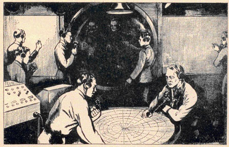
Figure 5-15. Information center at work.
5-16
COMBAT INFORMATION CENTER
outside his effective torpedo firing range. He can anticipate under what
conditions his own guns
are most effective and the enemy's least effective. He can decide by
comparison of speeds
whether pursuit is advantageous, and he can plan his use of clouds and
weather fronts for
evasion if that action is advisable.
CIC is the source to which the Captain turns for a specific tactical or
operational fact, for a
general summary, or for an opinion or suggestion. The CIC through the
evaluator, should
provide the Captain with the following data:
(a) Filtered contact, position and identify information presented,
according to the Captain's
requirements at the time.
(b) Tactical and strategical summaries, which include facts necessary for
the Captain's
information and decisions, but which omit all irrelevant material.
(c) Pertinent reports and background data which contribute to his
understanding of the problem
at hand, and to the resultant decisions.
(d) Evaluated comment, suggestions, and opinions, based upon the greater
availability of
information in the CIC.
The control function of the CIC, with its detecting, tracking, and
communication equipment, can
be of inestimable assistance in matters concerning both own armament and
coordination with
other units.
(a) With respect to coordination with, or control of own armament, the
CIC can:
1. Designate or suggest gun and torpedo targets.
2. Coach gun control on to targets.
3. Provide initial solution for gun computers.
4. Provide either point of aim and target
data in torpedo fire, or actually select torpedo course.
5. Control, designate, or warn automatic weapons in fire against planes
and torpedo boats.
6. Aid in delivering repeated anti-submarine attacks.
7. Control laying of smoke screen with respect to relative positions of
own and enemy forces.
(b) With respect to the coordination with, or
control of other units, the CIC can:
1. Control the details of radio communications, particularly voice radio,
with other units in
tactical company, thus relieving the Captain of this burden. This
includes use of such codes as
enciphered General Signals and the TBS and Fighter codes.
2. When own ship is senior, provide assistance in directing tactical
movements of other ships in company.
3. Provide fighter direction, designation of target for strafing and
bombing of shore objectives, or homing for aircraft.
4. Control movements of small craft, such as torpedo boats, landing
craft; and small minesweepers or minelayers.
5. Participate in coordinated radar, sound search and tracking.
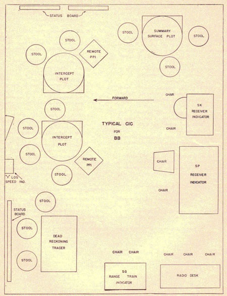
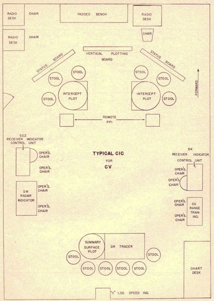
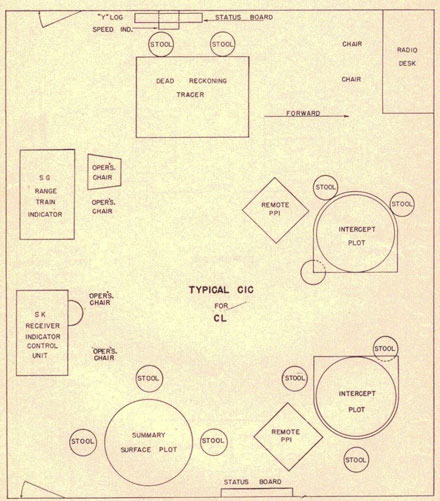
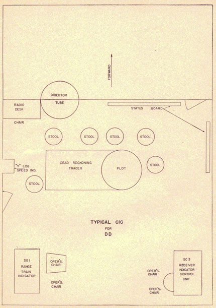
TYPICAL COMBAT INFORMATION CENTER
The Combat Information Center will he somewhat alike on all combatant
ships, but will differ as
to size, number of pieces of radar equipment, and personnel allowance,
depending on the ship
type. Some typical CIC layouts for BB's, CV's, CL's and DD's are
illustrated on the following pages.