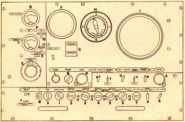
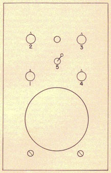
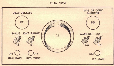
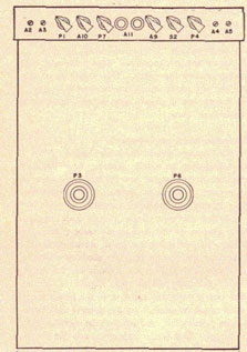
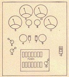
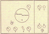
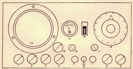
Working with the SG, the operator is concerned primarily with the range
and train indicator
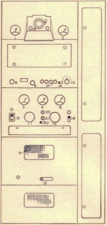
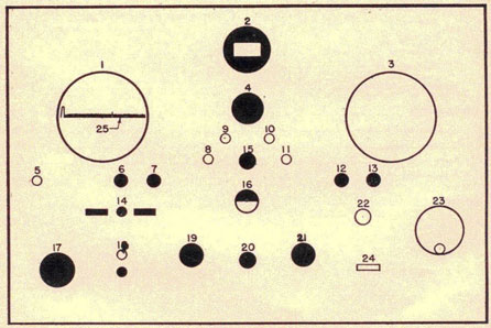
unit from which he can control the entire radar gear. A close-up of this
unit is shown in figure 4-SG-1.
All the controls on the range and train indicator may be divided into
three groups: power,
operating, and pre-set. All the power controls are grouped on the left
and extend from top to
bottom of the unit, except for the dial lights switch, which is at the
far right of the pre-set
group. The second group, operating controls, extend along the center of
the panel. The third
group is the bottom row of pre-set controls.
Identification and function.
It is important to be able to identify, and to know the functions of all
of the controls. For ease in
locating and identifying, all controls in figure 4 SG-1 are either
numbered or lettered.
1. The switch marked A is the remote control for the main-power switch at
the transmitter-receiver unit.
2. Meter B is identical to one located on the
transmitter-receiver unit, and indicates line
voltage. This meter should read between 110 and 120 volts AC. If it does
not, call the maintenance man.
3. The other meter, C, indicates transmitter current when switch K is in NORMAL position. Transmitter current as
indicated on meter C is
controlled by the setting of the variac (E). The variac should be set so
that the transmitter
current reading on meter C is between 15 and 25 milliamperes. If this
reading cannot be
attained, notify the maintenance man. With Switch K in MONITOR or
RECEIVER TUNE position,
meter C duplicates respectively RF. monitor and tuning indicator meter
readings at the transmitter and receiver
Figure 4 SG-1. Range and train indicator unit.
4-SG-2
SG RADAR
unit. When switch K is an the RECEIVER
TUNE position, it should read from 30 to 40 depending upon how well the
receiver is tuned. The
receiver should be tuned for maximum meter deflection. The meter reading
in the MONITOR
position will vary from time to time according to the way it is adjusted
by the maintenance man.
The operator should check the value at the start of his watch, and
periodically thereafter, in
order to determine whether any changes occur. The maintenance man should
be notified
immediately of any change.
4. The radiation switch D controls intermittent and continuous operation
of the transmitter. For
intermittent operation, switch D must be held in KEY position, as there
is a spring action that
automatically returns the switch to OFF position. LOCK position is for
continuous operation.
5. Variac (E) controls the power supplied to the transmitter.
6. The scope (F) is the range scope. Ranges
are read directly on the range counters (G). A modified method for quick
and approximate
readings is to place a calibrated scotch tape scale on the "A" scope
below the sweep. The same can
be done at the PPI (I) by drawing with india ink 5,000-yard circles for
the 15,000-yard
range; then, on the 75,000-yard range, these circles will be 25.000 yards
apart.
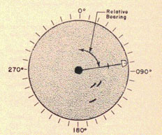
7-8. Bearing is read on indicator H and PPI (I). True bearing is read from
the outer scale, while
relative bearing is read from the inner dial, when synchro switch (J) is
in NORMAL position.
If ship's gyrocompass repeater system should fail, switch J must be thrown to
EMERGENCY for
equipment to operate, giving relative beatings only on the outer dial.
9. When the radar is operating, switch K is in the NORMAL position. The
other positions,
RECEIVER TUNE and MONITOR, are for purposes stated in 3 above.
10. Receiver sensitivity is controlled remotely by the operator through
receiver gain control (L).
11. Receiver's tuning is controlled remotely by the operator with
receiver tune control (M)
This is set for maximum return signals.
12. The range crank (N) is geared to the range counters and also moves
the step in the time
base on the range scope. Thus, lining up the step with the blip on the
range scope, the range of
the target can be read directly from the range counters.
13. There are two range scales. 15,000 yards and 75,000 yards. Switch P
permits the
operator to select either of the two ranges.
14. Switch Q allows the operator to receive either signals or range
markers on the range scope
and PPI. Normally this switch is on SIGNALS. In order to insure that the
gear will give accurate
ranges, the operator must cheek frequently (at least once each watch) the
range calibration by
switching range markers to the scope. This procedure is described later,
in the section on
Calibration.
15. The antenna's rotation may be controlled either manually or
automatically by switch R.
From its center position moving switch R to right gives automatic
clockwise rotation; moving it
to left gives automatic counterclockwise rotation. There are four
positions for four speeds on
either side of center.
16. Remote range switch (T) and remote bearing
switch (U) permit transmission of ranges and bearings, respectively, to
range and bearing
indicators located on the bridge, gun control, torpedo control, and
plotting rooms. At these
stations there are selector switches for cutting in either range and/or
bearing indicators. As a
rule, remote range and bearing are always in the ON position at the range
and train indicator
and OFF at the selector switches when bearings or ranges are not desired.
17. As a safety precaution against overloading the transmitter, there is
a relay which trips
during any overload condition. This relay can be reset by the operator by
pushing reset button (V).
18. Switch W will determine the positions OFF, INTERMITTENT, and
CONTINUOUS operation for
IFF equipment when it is installed,
19. Switch X adjusts the IFF gain.
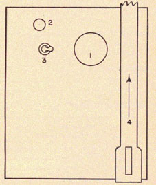
20. Range focus (1), permits the operator to adjust the sweep on the
range scope, permitting a
sharp, even trace for the entire width of the scope. This setting is made
on installing a new tube.
21. 15,000-yard zero set (2) adjusts the calibration for the lower end of
this range scale.
4-SG-3
RADAR OPERATOR'S MANUAL
22. 15,000-yard limit set (3) adjusts the calibration for the upper end
of this range scale.
23. 75,000-yard zero set (4) adjusts the calibration for the lower end of
this range scale.
24. 75,000-yard limit set (5) adjusts the calibration for the upper end
of this range scale.
25. Pulse frequency (6) controls the pulse repetition frequency. There
are three adjustments,
A, B, and C, which are used to reduce interference from other radars of
approximately the same
frequency. The control (6) is set on the letter giving the minimum
interference. This control
also is used for identifying second-sweep echoes. More will he said about
this in the technique
section.
26. PPI focus (7) permits the operator to adjust the sweep on the PPI for
a sharp, even trace.
27. Dial lights switch (8) controls the intensity of lights on the PPI,
bearing dial, and
counters. Pilot lights switch (9) controls light intensity for the red
and amber lights opposite
the stand-by and radiation switches (this control has been omitted on
later models).
28. There are five screwdriver adjustments with which the operator should
not tamper once the
set is operating normally.
H center adjustment (12) centers the time base on the range scope from
right to left.
V center
adjustment (13) centers the up and down position of the time base on the
scope.
PPI anode 2 (16) adjusts the sweep and signal intensity of the PPI screen.
PPI intensity (15) adjusts the intensity of the signal.
Marker amplitude (14) adjusts the height of the range markers, which
should be from 3/4 inch
to 1 inch in height.
29. There are two fuses with which the operator should he familiar. These
fuses are located on
the front panel near the transmitter current meter (C). One is marked
INDICATOR F-902 (10), and the other is marked BEARING CONTROL F-901 (11). If, for any reason, the antenna
or indicator should stop functioning, the operator should check these
fuses before sending for the
maintenance man There is a further description of these fuses in the
section on Operational
Technique. So far the controls on the range and train indicator unit have
been identified. The
operator should become so familiar with these controls
that he can make any adjustment automatically, even in complete
darkness.
TURNING ON AND OFF
Turning on.
Let us assume that the transmitter and receiver unit are ready for
operation. When starting the
gear for the first time, check to see that the controls are set as
follows:
1. Turn the main-line power at the remote control switch (A) to STANDBY.
2. Set the radiation switch (D) in the OFF position.
3. Turn the variac (E) to zero (extreme counterclockwise).
4. Place synchro switch (J) on NORMAL position.
5. Turn receiver gain (L) down.
6. Throw signal-markers switch (Q) to SIGNALS.
7. Turn bearing switch (R) to NORMAL.
8. Set rec-tune, normal, monitor switch (K) to NORMAL.
Steps 1 through 8 represent the normal settings of the range and train
indicator unit when
equipment is on STANDBY, and from which the SG can be placed in operation
as follows:
1. Turn the standby-on switch (A) to the ON position. The amber pilot
light will indicate that
power is available. Check the line voltage on meter (B), which should
read between 110 and 120 volts.
2. Throw the radiation switch (D) to LOCK position. After about one
minute, the red pilot light
will glow, indicating that the transmitter is ready.
3. Turn the variac (F) slowly to the right until the transmitter current
meter reads 25
milliamperes or less.
4. Turn the receiver gain control (L) up until about 3/8-inch grass
appears on the range
scope.
5. Start antenna rotation by turning the switch (R) to right or left.
Turning off.
In order to shut down the equipment the above procedure should
be reversed.
1. Stop antenna rotation by turning switch (R) to the center position,
leaving antenna on 000 degrees
relative bearing.
4-SG-4
SG RADAR
2. Turn receiver gain control (L) down.
3. Return variac (F) to zero (extreme counterclockwise).
4. Turn radiation switch OFF.
5. Throw the power switch (A) to STANDBY.
CALIBRATION
Calibration of the range counters.
To make sure that the equipment will give accurate range readings, the
operator should check
the calibration of the range counters at least once every watch (every
four hours). To do this,
the range selector switch (P) is first set to the 15.000-yard position
and the signal-markers
switch (Q) to the MARKERS position. Markers representing divisions of
5,000 yards
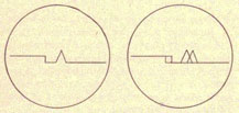
appear along the time base on the range scope. The operator now turns the
range crank (N) until
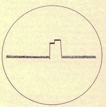
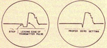
the 15,000-yard marker just begins to "pull down" into the step. The
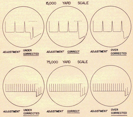
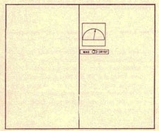
diagram in figure 4 SG-2 illustrates how the step should appear when adjusted to the correct
position. If accurate, the
range counters should read exactly 15,000 yards. Next, the step is lined
up with the center of
the 5,000-yard marker. Now, the counter should read exactly 5,000 yards.
The operator also checks the counters on the 75,000-yard range scale, Then, if the selector switch is in the 75,000-yard
position, a series of
markers will appear on the time base, each representing distances of
5,000 yards. The
appearance of these markers will vary somewhat on different
installations, and this difference
must be clearly understood if the calibration is to he done correctly.
The zero marker may or may not
Figure 4 SG-2. Correct calibration at 15,000- and 75,000-yard ranges scales.
4-SG-5
RADAR OPERATOR'S MANUAL
be visible at the left end of the time base. However, there should not
be any confusion as to
whether the first visible marker represents zero or 5,000 yards. If the
zero marker appears,
it will just he seen at the extreme left end of the time base. lithe
first visible marker is some
distance from the beginning of the time base, it is the 5,000-yard marker.
The step is first lined up with the center of the 5,000-yard marker, and
the range counters
should read exactly 5,000 yards. Next, the step is cranked until the
75,000-yard marker
begins to drop down. The counters should read exactly 75,000 yards. The
75,000-yard marker
will be the sixteenth or fifteenth, depending on whether the zero marker
is, or is not visible.
If the calibration of the range counters is not correct, the operator
will perform the following
operations:
1. Turn the signal-markers switch (Q) to MARKERS.
2. Set the range switch (P) to the 15,000-yard position.
3. Turn the range crank (N) until the range counter reads exactly 15,000
yards on the lower
scale. Unlock the 15,000-yard limit set control (3), and adjust it until
the top of the fourth
range marker at the far right just begins to "pull down" into the step.
Lock the control in this
position.
4. Change the range switch (P) to the 75,000yard position. If the range
crank has not been
move], the top counter will read 75,000 yards. Unlock the 75,000-yard
limit set control (5),
and turn it until the 75,000-yard marker (fifteenth or sixteenth from the
left) begins to "pull
down" into the step. Then lock the control again.
5. Turn the range crank (N) until the top counter reads 5,000. Unlock the
75,000-yard zero
set control (4), and adjust it until the 5,000-yard marker (first or
second from the left)
begins to drop. Lock the control.
6. Switch to the 15.000-yard range, and turn the range crank until the
bottom counters read
5,000. Now unlock the 15,000-yard zero set control (2) and adjust it
until the 5,000-yard
marker begins to drop. Lock the control.
7. Re-check the upper limits on both range scales.
External calibration.
It is important that the external calibration of the set he checked
periodically. This may be done
by using one of three methods. It may be determined
by comparison with fire-control radar, by ranging on some target whose
distance can he
determined precisely, or by observation of a double range echo. A double
range echo is a false
echo that will sometimes appear on the same bearing as a target, but at
twice the range of that
target. These echoes are most evident when the target ship is on a
parallel course, close abeam,
and large. If the real echo appears at 800 yards and the double range
echo appears at 1,800
yards, the correct range of the target will he the difference between the
two, or 1,000 yards.
Since, in this example, your radar measured the range as 800 yards, the
set's individual,
constant error would be 200 yards, making all ranges low by that amount.
Be sure the set has been warmed up and calibrated carefully before trying
to determine its
error. When determined, the error can be compensated in calibration.
Thus, to compensate for
the error in the above example, set the range dial to 5,200 yards, and
15,200 yards instead of
5,000 yards and 15,000 yards,-line up the first and third range marks
with the step as
before. Now all ranges read on the 15,000-yard scale will he 200 yards
higher and therefore
correct. Make the same compensation on 75,000-yard scale.
OPERATIONAL TECHNIQUE
Tuning the receiver.
The operator has only one tuning control to adjust. This control is the
knob marked receiver-tune (M) located next to the range crank.
When the set is turned on from the stand-by condition, it takes about
twenty minutes for the
oscillator frequency to become stable. The tuning will have to be
adjusted frequently if the set is
to be used during this first 20 minutes. After this "warm-up" time the
tuning will be fairly
stable, but should be checked at least every half hour, or by each new
operator. Experience will
indicate how often your particular set must he tuned. Some sets require
more frequent tuning
than others.
The following procedures are used to tune the receiver:
Land echo. The best method is to tune on a land echo. Stop the antenna in
order to get a good steady
land echo on the "A" scope. Turn the gain down to where the echo is not
saturated (to where it is
about half of its maximum height). Then adjust the receiver-tune control
(M) until the signal
is at its maximum height. The technique for determining maximum signal
height is to turn the
tuning control rapidly when approaching the maximum height, going a
little beyond and a little
under maximum signal, and
4-SG-6
SG RADAR
then estimating the mean (average) setting between these two points.
During tuning, always
keep the signal below saturation by adjusting the receiver gain control
(L), and make the setting rapidly.
Ship echo. The next method is similar to the foregoing but is not so
effective. Tune on an echo
from another ship. The same procedure is used; however, trouble will be
experienced because
the echo will bounce up and down. Tuning on an echo of this type requires
a certain amount of
skill and experience.
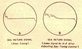
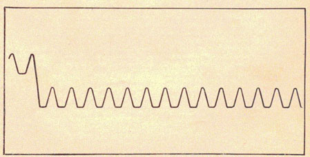
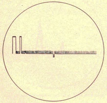
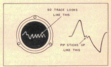
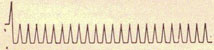
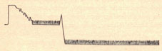
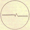
Sea-return. Another method, which, under certain conditions such as
especially heavy weather
is better than tuning on ship echoes, is to tune for maximum sea-return.
The sea-return consists of many bouncing echoes which extend out,
sometimes as far as 6,000
yards. The operator should operate the set on the short-range scale,
watch the "A" scope, and
tune for the point where overall sea-return is highest and extends out to
the greatest range. An
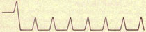
illustration of how sea-return should appear is shown in figure 4 SG-3.
Meter. If there are no echoes or sea-return available for tuning, throw
the receiver tune-normal-monitor switch (M) to the RECEIVER TUNE position. Then tune for the highest reading
on the transmitter current meter (C), using the receiver tune (M)
control. Do not fail to
return switch to NORMAL after tuning, since in receiver tune position,
ranges will be 500 yards off.
Fig. 4 SG-3. Sea-return on the "A" scope using 15,000 yard range scale.
Long-range search or large target search.
The "A" scope will show targets at greater ranges than the PPI;
therefore, it is necessary that
the "A" scope he used in the long-range search. The PPI is, however,
much easier to watch, and
once a target appears on it, there will he little chance of the operator
missing the echo.
Because of the above considerations, a long-range
search should use both the "A" and PPI scopes, with the following
procedure:
Switch to the 75,000-yard scale and adjust the receiver gain for about
3/8-inch of grass on
the "A" scope. Then, for approximately five minutes, search with the
antenna on automatic
rotation at the slowest speed. The operator should watch the PPI for two
antenna sweeps, then
the "A" scope for two sweeps, then the PPI for two more, and so on for
the rest of the five
minutes. At the end of this time, switch to hand rotation and make a slow
hand rotation of a full
360 degrees, watching the "A" scope very carefully. After this, repeat the
automatic rotation search.
The speed used for automatic rotation is 4 rpm in the first position.
Some ships have changed
this so that the first position now has an antenna rotation speed of 1 or
2 rpm. If the set aboard
your ship does not have a rotation as slow as this, the technician can
easily change it to the
desired speed. When this adjustment has been made, the operator can use
the second speed of
rotation, 4 rpm, for normal search, and lie can use the first speed in
place of the hand search.
Close-range search or small target search.
This type of search is primarily intended to detect surfaced
submarines, periscopes, or PT
boats, although it has other functions. The following procedure
should he used.
Switch the range to the 15,000-yard scale. The search is conducted by
watching the PPI scope,
using an antenna speed of 1 or 2 rpm, (or 4 rpm if that is the slowest
available).
Two conditions requiring special attention are likely to be encountered
in this type of search.
The first is sea-return, which may extend to 1,000 or 2,000 yards, and in
rough weather to
6,000 yards. With the receiver gain up to its normal value, targets at
close range will be
hidden in this sea-return. To detect, or to get bearings and ranges on
targets under these
conditions, it is necessary to reduce receiver gain. It should be borne
in mind, however, that the
gain is reduced only when checking these close targets, and then only for
a very short time,
since the gain must be up if the small echoes from submarines are to be
detected.
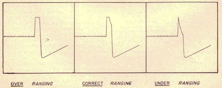
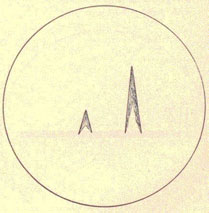
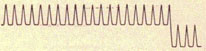
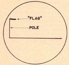
The other thing requiring consideration on this range is the saturated
echo. Targets at such
short ranges give strong echoes. On the "A" scope these echoes are
saturated; that is, they have
flat tops. To get an accurate range on this type echo, the range dial
should be cranked to a point at which one-half of the
4-SG-7
RADAR OPERATOR'S MANUAL
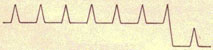
flat top drops off into the step. The illustration in figure 4 SG-4
shows the correct means of
ranging on a saturated pip.
To get an accurate bearing on these strong echoes, the PPI should be
used. Rapidly rotate the
antenna back and forth so that the entire echo is visible on the PPI;
then quickly stop the
antenna so as to bisect the echo.
Station keeping.
For station keeping, it is not usually necessary to obtain extremely
accurate ranges and
bearings. In normal steaming, ranges and bearings to the guide ship may
he obtained with
sufficient accuracy for keeping station without stopping the antenna
rotation. The PPI scope is
used to approximate the bearing. The bearing is read off the scale
surrounding the PPI by
mentally drawing a line from the PPI center through the target to the
scale. The range may be
approximated by several different methods. The best method is to mark
permanent 5,000-yard
circles on the PPI with India ink-, and to estimate range in relation to
these. A second method is
to switch the signal-markers switch to MARKERS. As the antenna rotates,
5,000-yard circles
will remain for a few seconds after the switch is turned back to SIGNALS.
The range to the target
may be estimated by noting its position relative to the marker circles.
The third method is to
put a piece of scotch tape on the "A" scope and ink a scale of ranges on
it. Then, as the antenna
sweeps by the target, the operator watches for the pip to jump up on the
range scope and obtains
the range from the scotch tape. A new rotating scale device is being
placed on the PPI's of many
of the SC's in the Elect. The range and bearing of target
may be estimated by simply rotating the scale to coincide with the
target. This device has two
disadvantages: first, the range scale is inaccurate; second, it obscures
the view of the PPI. A
more satisfactory device is under development.
The above-mentioned methods of approximations are usually satisfactory
for normal station
keeping. While taking a new station, or during formation changes, it will
usually be necessary
to get accurate ranges and bearings in the normal way.
Radar was not meant to supersede regular station keeping methods. Since
such use cuts down the
search efficiency, employment of radar for station keeping should be kept
to the absolute minimum.
Auxiliary fire control.
The SG may he called upon for fire-control work, especially torpedo
fire-control on destroyers.
There is always the possibility that the fire-control radars may be put
out of commission,
making it necessary to use the SG to obtain accurate bearings and ranges
to be used in the
computers. This can best be done by stopping the antenna. However, since
such procedure cuts
down the efficiency of the search, tracking should be carried on without
stopping the antenna
unless accuracy is absolutely vital. It is recommended that at least one
360 degree sweep be made per
minute while tracking, to guard against surprise.
Shell splashes can be picked up when the antenna is trained in the
direction of fire. On the "A"
scope the echo will jump up rapidly, and a quick estimation of range
difference between it aid
the target echo may he made. If the antenna is rapidly rotated back and
forth by hand so as to
cover a small sector near the target, the splashes may appear on the PPI.
It is
Figure 4 SG-4 Correct method for ranging on a saturated signal on the
15,000-yard range scale.
4-SG-8
SG RADAR
possible to do very rough spotting in both range and deflection by
estimation from the PPI.
Navigation.
The SG is extremely useful to the navigator, particularly when operating
in close waters. The
navigator who is always cognizant of the ship's position will he able to
give the operator the
approximate bearing, distance, and expected time of contact with land.
From his chart lie will
be able to tell if the land rises abruptly out of the water, or, in case
the land is low lying near
the beach, whether or not it rises farther inland.
Land that rises at the water's edge to considerable height is excellent
for radar purposes since
the closest land appearing on the PPI in this case, is usually the beach.
The chart should always
be checked for the possibility of inland mountains appearing; first, by
checking the altitude of
mountain peaks against the altitude of the shore line, and second, by
checking the outline of the
shore from the chart against the outline from the PPI. In eases of this
type of land, the outlines
will be almost identical, and comparison with the chart may be used to
fix the ship's position.
Almost all the islands in the Aleutians are of this type.
Another type of situation involves a low-lying shore line and inland
mountains. When contact is
first made, only the mountains will appear on the PPI, since the low
shore will be below the
horizon. With this type of land it would be a dangerous mistake to assume
that the beach is the
closest contact. Failure to remember this may result in the ship's
grounding. For this same
reason, unless your knowledge of the contour of the land justifies it,
never depend on bearing
tangents for fixing your position.
The best fixes are not necessarily obtained from a large group of random
ranges and bearings,
or from the closest land. The best method is to obtain a few accurate
ranges and bearings of
small prominent objects. Isolated rocks, small distinct islands, and
isolated mountain peaks are
excellent for obtaining fixes. The prominent points may be chosen from
the chart. If the ranges
and bearings obtained on two or three of them plot in at the same point,
it is safe to assume that
that point is your position.
Always remember to make use of the contours of the land when employing
radar for navigation.
By closely examining the echo of the "A" scope for multiple peaks and
other peculiarities, the
echo may be more definitely fixed to some position on the chart.
Islands in the mid-Pacific are very flat, and rise only a few feet above
sea level. These islands
are usually
hounded by coral reefs and shoals, so extreme caution must be observed
while using radar
navigational fix taken close to them. Lack of small prominent points on
these islands makes it
difficult to obtain reliable fixes.
Sometimes it is possible to detect shoals on the radar screens, if the
shoals are close enough to
the surface to cause a disturbance in the water. The signal appearing on
the radar screen would
be much the same as a "wake" signal obtained from another ship. However,
shoals are very
treacherous and ships should not rely upon radar to detect them.
Composition.
When a contact is detected on the SG, it is extremely important that
certain facts be determined
about its composition. Ability to obtain these facts comes largely from
experience, but the
following hints may be of value.
Type and number of ships. The range of initial contact is the best
indication of target size. Fixed
antenna height results in ships of a certain size usually having a
certain maximum range. Thus,
on a ship where it is usual to contact battleships at 40,000 yards and
destroyers at 25,000
yards, first contact at 38,000 yards would indicate a ship of battleship
size.
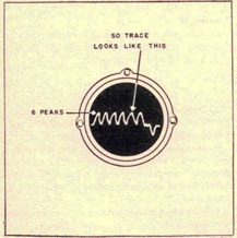
Echoes from large ships will he much steadier than those from small
ships, and will usually
appear thicker on the "A" scope. On first contact or at great distance,
the "A" scope should be
used for determining the number of ships in a contacted group. Turn the
receiver gain down, and
examine the top of the echo for multiple peaks, counting as many as
possible. It should be
remembered that when contact is first made, only the large ships will
appear, since the smaller
ones will still be out of range.
Aircraft. Pips from aircraft will appear quite erratic, the echo
fluctuating rapidly on the "A"
scope. On the PPI they are apt to appear very strongly on the antenna
sweep, be absent on the
next sweep, and appear at some other position on the next sweep. They may
be recognized by
their fluctuating echo and rapid change of position.
Land. Land echoes are steady and are likely to be quite wide. When
plotted on the DRT, their
position will remain stationary.
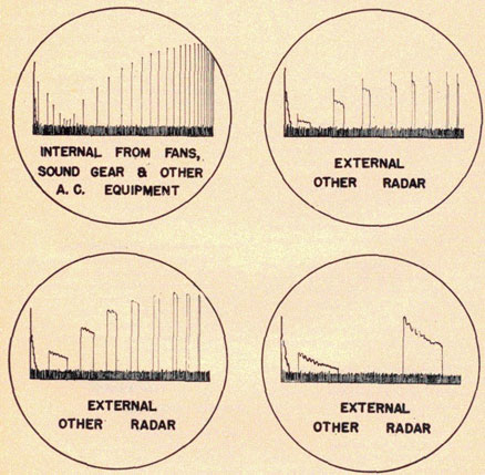
False echoes. Various types of false echoes are encountered with the SG.
They are not caused by
trouble in the equipment, and are not truly false for they are actually
caused by some reflecting
surface. They are, however, considered false because they indicate
objects in which we are not
interested.
4-SG-9
RADAR OPERATOR'S MANUAL
Multiple-reflection echoes are caused by the beam reflecting between
several ships in a group
before returning to the antenna. The bearing of the echo will be the same
as one of the ships.
Because of the changing position of the ships, this type of echo will
disappear very quickly.
In close formations, double-range echoes are quite common. They are
caused by the returning
echo reflecting off the searching ship, again reflecting off the target,
and finally reaching the
antenna. This type of false echo may be recognized by three factors;
first, it will always be at
the same bearing as one of the large targets; second, it will be at
exactly twice the range of the
large targets; and third, it will vary rapidly in amplitude.
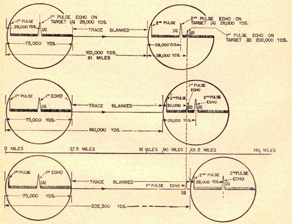
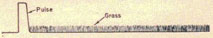
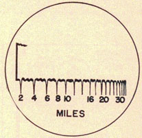
Second-sweep echoes result from long-range echoes arriving back after the
next sweep has
started. With a pulse rate of 1,000 c.p.s., there is time for 81 miles of
range between each
pulse and sweep. Thus, for an echo to appear on the second sweep it must
be over
81 miles away. Trouble will be experienced with this type of echo only
when there is high land
over 81 miles away. In order to know when second-sweep echoes are likely
to be encountered,
the operator should be constantly aware of the ship's position in
relation to land. To check this
type of false echo, the pulse rate should be changed. If the echo is of
the second-sweep type, it
will shift in range or disappear entirely. Although these echoes are
rare, they should be
recognized and understood. Figure 4 SG-5 shows a graphic representation
of how the second-sweep echo pip will shift its position on the "A" scope as the pulse
frequency is varied.
Another type of false echo results from reflection off some part of the
ships structure. These
echoes occur when the mast or superstructure is in the path of the
radiated beam. The energy
reflects off the interfering structure, hits the target, and returns by
the same route. The false
echo will be at the same range as some real target and on the bearing of
the
Figure 4 SG-5. Second-sweep echoes.
4-SG-10
SG RADAR
interfering structure. The SG also has side lobes 60 degrees to 70 degrees on either side of
the main lobe. They will
often show up on a large target which is within 5,000 yards.
PPI echoes. When cruising in close formation with other ships, the
picture that appears on the
PPI will give the impression that we can determine the course of each
individual ship simply by
observing the PPI. This is definitely not true; although all the ships
are on a similar course,
each appears on the PPI to be on a different one because of the curved
pip resulting from the
radial sweep.
Jamming and deception.
There is no doubt that the enemy considers our radar an extremely
dangerous weapon, and
consequently it is only reasonable to expect him to try every means
possible to make it less
effective. He may use two tactics to do this: jamming and/or deception.
Every operator should
learn how to recognize these countermeasures, and expect them when in
combat zones.
When the enemy broadcasts radio signals intending that our radar receive
them, and they show a
confusing pattern on the screen, it is called jamming. Use of dummy
targets (tinfoil, kites,
balloons, etc.) is called deception. More precise definitions are
sometimes given, but these are
satisfactory for this discussion.
The SG radar can be jammed, and it will show echoes from the tinfoil the
enemy sometimes
throws out to confuse the operator. The operator should not become
alarmed when either of these
things happen.
If you were suddenly confronted with jamming without previous experience,
it would appear
impossible to work through. However, it is not really that serious if the
following procedure is
carried out:
1. DF on the jamming.
2. Use available anti-jamming devices on receiver when provided.
3. Try moving the gain control up and down.
4. Try changing the receiver local oscillator tuning.
5. Keep operating.
6. Report the type and bearing of jamming to CIC.
The first reason for obtaining a bearing on the jamming is to determine
whether or not it could
be accidental interference. Jamming will not only be directional, but its
true bearing will not
be changed by any sudden change in your ship's course. Interference
originating aboard your
own ship will either be non-directional and appear on all bearings, or
else it will
always be on some certain relative bearing regardless of own-ships course
changes.
Try moving the gain control up and down. This is probably one of the most
important
countermeasures that can be taken, and the one most commonly overlooked
because of its
simplicity.
In most cases, except when effective noise modulated jamming is being
encountered, there is a
setting of the gain control with which it is possible to range on a
target in the presence of heavy
jamming. If there are several echoes on the same bearing, the best
setting for each echo is
different. Of course it is more difficult to obtain these ranges because
of the distortion of the
echo produced by jamming, but it is, after all, possible to obtain the
desired information. The
extra effort is worth while because the enemy would not be jamming unless
he were trying to
conceal something important.
Two general methods of using the gain control, both of which should be
tried, are as follows:
1. Reduce setting; this prevents overload of radar receiver; echoes are
visible "riding on top" of
the jamming pattern.
2. Increase setting; this limits (or clips) jamming; echoes are visible
as a break in the base line.
Try changing receiver local oscillator tuning. When you change the rec.
tune, you lose some of
the height of the desired echo. However, if the jammer is not exactly on
your radar frequency,
there is a chance that you will detune the jamming signal more than the
echo signal.
Considerable improvement can sometimes be obtained in this way. Try
"swinging" the rec. tune
dial in both directions to see which direction brings the greatest
improvement. Note the correct
setting of the rec. tune dial so that it can be returned to its normal
position when no jam is
present, or if detuning does not help.
Keep operating. Even if the jamming is extremely effective, keep trying
and do not turn your
radar off. Turning your radar off informs the enemy that his jamming is
effective, and
certainly makes the radar completely worthless. The effectiveness of the
jamming may change
from time to time, so if you are persistent enough some information may
be obtainable.
Report the nature and bearing of jamming to CIC. Recognizing the type may
be difficult because
nonsynchronous patterns sometimes appear blurred beyond recognition.
Inasmuch as knowledge
of jamming type * may possibly help identify the jammer
* See Part 3, Defense Against Jamming and Deception.
4-SG-11
RADAR OPERATOR'S MANUAL
in some cases, this information should he reported if possible.
If the equipment is provided with an anti-jamming receiver, the jamming
may be reduced
sufficiently for reading targets without any detuning of the receiver.
Detuning should be
undertaken as a last resort, and then should be done very carefully and
cautiously; otherwise all
targets may be lost and the procedure made completely ineffective. No
special method is offered
for setting the controls of the AJ receiver, except that they should be
varied for minimum
jamming, the gain control coming first, and then the A\TC control.
Above all, never turn off the radar.
When jamming and/or deception is encountered, full 360 degree search must be
continued. However,
the antenna should be stopped for short intervals from time to time, in
order to try reading
through the jamming (using the "A" scope). You also must be prepared for
any diversionary
tactics, for the enemy may or may not use jamming and/or deception to
divert your attention
from the bearing of the main attacking forces. This problem is simplified
somewhat when
similar but separate radars are used for
reading through jamming and for searching.
PERFORMANCE
Maximum reliable range.
Ranges in surface craft obtained with the SG are dependent on the antenna
height. Expected
ranges with a typical antenna height should he of value to the new
operator.
The results listed below are maximum reliable ranges for a 90-foot
antenna.
Accuracy.
Range accuracy is +/- 150 yards.
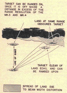
Bearing accuracy is +/- 1 degree.
Resolution.
Assuming two targets to be on the same bearing, the SG can distinguish
between them at short
ranges when they are separated by no more than 300 yards; at longer
ranges approximately
500 yards separation is needed. At any range, too high gain tends to
cause the pips to merge, and
reduces discriminatory power. In general, the SG is able to discriminate
in range between two
targets separated by 300 yards or more on the "A" scope, and 500 yards on
the PPI.
With respect to bearing, a comparable minimum limit exists and is
expressed in angular rather
than linear measurement. Since the transmitted beam does not travel along
a single line, but has
an angular spread, it can be seen that if there are two targets at the
same range, one in the
center of the beam pattern and the other in the edge, an echo will be
returned from the target in
the center and from the target in the edge, and these will appear as one
echo. By reducing
receiver gain it will often be possible to distinguish both targets. At
normal ranges the angular
separation necessary for target discrimination in bearing is 5 degrees using the
"A" scope, and 9 degrees using the PPI.
TROUBLES
Major troubles are handled by the technicians but time will be saved if
the operator is able to
recognize some of the minor breakdowns.
If the sweep traces on the "A" and PPI scopes suddenly go out, the
indicator fuse next to the "A"
scope should be checked,
Type of target.
SG
SG-A and SG-1
BB, CV, Large auxiliaries
35,000-45,000 yards
45,000-55,000 yards
CA, CL, Medium auxiliaries
28,000-35,000 yards
30,000-40,000 yards
DD, DM, AV, PC
18,000-30,000 yards
25,000-35,000 yards
Submarines
9,000-12,000 yards
11,000-15,000 yards
Submarine periscope
2,000-4,000 yards
2,000- 4,000 yards
Large planes (altitude 1000'-3000') PBM, PBY, PBZ
20,000-35,000 yards
20,000-40,000 yards
Small planes (altitude 1000'-3000') SOC, OSZU, SBD, F4F
10,000-15,000 yards
12,000-21,000 yards
Minimum range.
SG
SG-A and SG-1
Ship
600 yards
600 yards
Plane
1,000 yards
1,200 yards
4-SG-12
SG RADAR
If the antenna and "bug" will not turn when the antenna is switched to
automatic rotation, the
bearing fuse next to the "A" scope should be checked.
If the red light goes out, sweeps disappear, and the plate current drops to
zero, the overload
relay probably has kicked out. Torn the high-voltage variac all the way
down, press the
overload reset, wait for the red light to come on, and then turn up the
variac to the proper value.
When ranges appear to be 500 yards too high, the receiver-tune- normal
monitor switch
should be checked to see if it is on NORMAL position.
If the sweeps on either scope appear fuzzy, their respective focus controls
should be adjusted.
There are certain occurrences which are entirely normal on the SG but which
might be
interpreted as troubles by the new operator.
If the synchro excitation to the antenna control motor should fail, the
operator will be able to
detect the trouble almost immediately. When the synchro supply goes out,
the antenna will stop
rotating, even though the "bug" continues to rotate and the sweep continues
on the PPI. However,
the picture on the "A" scope will stay constant because the antenna is not
rotating, and the
picture on the PPI will appear
as a series of markers described through 360 degrees. When this condition exists,
the operator should do the following:
1. Shift the switch on the gyro-control panel from the forward gyro to the
after gyro supply or
vice versa.
2. If this does not correct the situation, shift the synchro switch on the
R and T indicator from
NORMAL to EMERGENCY and continue to operate, reading relative bearing only
on the outer dial.
If the synchro excitation should fail while at sea, and there are no
targets on the screen, it will
be difficult to detect what is wrong. The operator might detect the trouble
by close observation
of the "A" scope for changes in sea-return signals. If there seem to be no
changes in the signals
the operator should have someone cheek visually to see if the antenna is
rotating.
Sometimes targets will be obscured by radar interference. This appears as
either a series of
dots, or as a series of radial lines on the PPI. There is not much that can
be done to correct the
situation: however, changing the pulse rate sometimes changes the
interference pattern so as to
make it less objectionable. When interference is severe, use the "A" scope.
The SC radar is now obsolete and will not be dealt with in this
discussion. The controls on the
control unit and the receiver indicator unit, which the operator uses,
are the same as those of
the SC-1. The SC-1 radar is a modification of the SC. The transmitter was
re-designed to increase
the power output, and the antenna was modified. A preamplifier unit has
been added to most sets.
The SC-2 radar is similar to the SC-1, but incorporates a few
modifications. The sweep circuit
has been revised, and the antenna has been re-designed, with a
directional IFF antenna included.
A PPI unit has also been added. The SK radar at present is an SC-2 with an
antenna four times as
large. The SC-2 or SK radars are composed of six units, as follows:
1. The control unit.
2. The receiver indicator unit.
3. The transmitter.
4. The preamplifier.
5. The plan position Indicator unit.
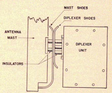
6. The antenna, together with transmission line and duplexer units.
The operator is concerned principally with the first two units, and
possibly with the fourth,
and the duplexer unit of the sixth. Ordinarily, the technician tunes the
transmitter,
preamplifier, duplexer, and receiver. The operator checks the tuning of
the receiver at the
beginning of his watch.
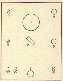
CONTROLS
Control unit.
A. Main power switch: controls power to all units.
B. Transmitter-plate voltage: this switch,
when snapped on, applies all power to the transmitter. As it is turned
clockwise, it increases
the high voltage applied to the transmitter tubes.
C. Relative-true bearing switch: when on TRUE the antenna is controlled
by the ship's gyro
system. Relative bearings are read on the outer dial, and true bearings
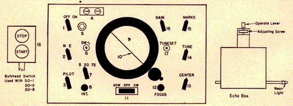
on the inner dial of bearing indicator (M). When on RELATIVE, the antenna is controlled by power from the set. This maintains antenna control in the event that gyro power fails. Only relative bearings to the outer dial may then be read.
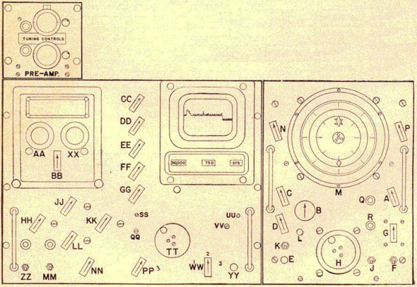
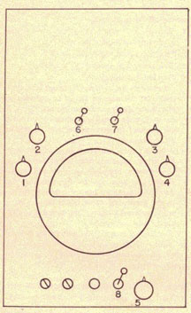
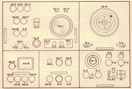
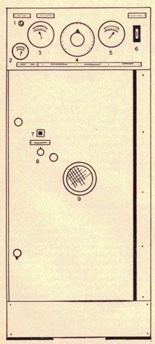
Drawing of receiver, indicator and control unit front panel.
4-SC/SK-2
SC-SK RADAR
D. Remote bearing indicator switch: applies control power to remote
bearing repeaters.
E. Remote bearing mark: buzzer or horn switch to notify remote station when readings may be taken.
F. Automatic-manual toggle switch: power switch to slewing motor, which
gives automatic antenna rotation.
G. Antenna-control switch: center position is off. Right gives clockwise
rotation. Left gives
counterclockwise rotation. Speed is controlled by the amount of turning.
H. Hand crank: for antenna control.
J. BL power switch; may or may not be used.
K. Sweep: local-PH; PPI position used when in sector search. Local position
is the normal operating position.
L. Overload relay reset.
M. Bearing indicator: inner dial-true; outer dial-relative.
N. Brightness control of bearing indicator light.
P. Brightness control of pilot lights.
Q. Transmitter pilot light.
R. BL power pilot light.
Receiver unit.
AA. Radio frequency tuning control.
XX. Local oscillator tuning control.
BB. Receiver gain control.
Indicator unit.
CC. Receive-calibrate switch.
DD. Dial light brightness control: controls brightness of the pilot lights and range-counter lights on the indicator unit.
EE. Brilliance control: controls brightness of the trace.
FF. Focus control: controls width of the trace.
GG. Astigmatism control: controls uniformity of focus along length of the
sweep.
HH. IFF gain control.
JJ. Calibrate maximum.
KK. Calibrate frequency.
LL. Calibrate minimum.
MM. Challenge switch for IFF: puts the IFF system into operation from
standby.
NN. Synchronizing switch: EXTERNAL-INTELNAL: normal operating position on
EXTERNAL.
Brings synchronizing pulse from transmitter to the indicator. INTERNAL
position may be used
for adjusting sweep and calibrating frequency when high voltage has not
been turned up.
PP. Crystal switch.
QQ. Range step height control.
SS. Vertical trace centering control.
TT. Range crank.
UU. Horizontal sweep centering control.
VV. Synchronizing pulse gain control.
WW. Range selector switch:
Range 1-30,000 yards
Range 2-75 miles
Range 3-375 miles
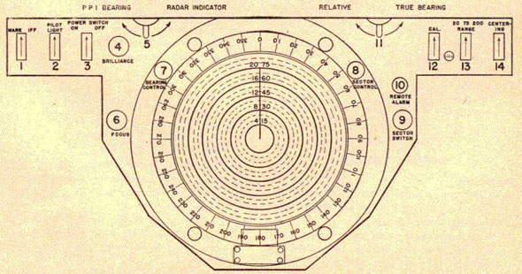
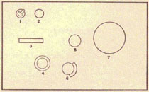
Figure 4 SC/SK-2. Plan position indicator.
4-SC/SK-3
RADAR OPERATOR'S MANUAL
VV. Remote range mark: remote alarm switch,
ZZ. Power switch for receiver indicator unit.
PPI unit.
1. Mark-IFF switch: normal operating position on IFF. When on MARK, range
step is shown on PPI.
2. Dimmer control for PPI bearing dial light.
3. PPI power switch.
4. Brilliance control.
5. Bearing indicator switch; RADAR-PPI: when on RADAR, bug follows the
antenna; when on
PPI, bug follows the yoke (cursor).
6. Focus control.
7. Bearing indicator adjustment control: for synchronizing bug reading
and cursor reading,
when operating bearing indicator switch is in the PPI position. Depress
knob and set cursor
(bearing blade) to read with the bug, then release knob to again engage
the cursor.
8. Sector search control: in normal position, which is DOWN, clockwise
rotation of the control
increases the sector. Counterclockwise rotation narrows the sector. When
pulled UP to engage
the cursor, the sector may be rotated by rotating the cursor.
9. Sector search off-on switch.
10. Remote alarm button.
11. Relative-true switch for PPI.
12. Calibration control.
13. Range selector switch:
Range 1-20 miles
Range 2-75 miles
Range 3-200 miles
14. Centering control: controls only centering of sweep along axis of
sweep.
Preamplifier unit.
1. All controls on the preamplifier unit are tuning controls.
TURNING ON AND OFF
Turning on.
1. Turn the main power switch (A) ON. The dial light of the bearing
indicator will light, and the
amplidyne motor will start,
2. Turn the transmitter plate voltage variac to 10. The pilot light (R)
will light up and the
filaments in the transmitter oscillator and power supply will glow.
3. Turn ON receiver indicator power switch (ZZ). Pilot light (RR) and the
lights on the range
counter will light. After a few seconds, a trace will be seen on the
range scope, unless the
brilliance control (EE) is fully counterclockwise.
4. Turn ON the power switch of the PPI unit. The lamp for the bearing
glass will light.
5. After waiting a half minute, the filaments of the transmitter tubes
will be hot, and the plate
voltage variac (B) should be turned slowly up to between 70 and 100. This
value is determined
by the technician.
6. Turn on BL power switch (J).
7. Start the antenna rotating by setting switch (F) on AUTOMATIC, and
switch (G) to give a slow
rotation of the antenna.
8. Turn up PPI intensity control (4) until a trace appears.
9. Adjust focus (6) to get fine uniform trace.
10. Center sweep with control (14). This adjustment should be made so
that the beginning of
the sweep starts at the same point regardless of the bearing. That is,
there is no overlap of the
sweep and no open portion. If the center of the sweep is not at the
center of the scope, the
technician must make internal adjustments.
Turning off.
1. Turn down (CCW) PPI intensity control (4).
2. Turn off power switch for PPI unit.
3. Turn off BL power switch (J).
4. Turn off automatic switch (F).
5. Turn switch G to OFF position.
6. Turn off receiver indicator power switch (ZZ).
7. Tarn plate voltage variac fully CCW.
8. Turn off main power switch (A).
CALIBRATION
Calibrating the range scope.
1. Turn switch (CC) to CALIBRATE.
2. Turn switch (WW) to Range 1.
3. Adjust brilliance (FE), focus (FF), and astigmatism (GG) for a fine
uniform trace. These
controls interact one on the other, and must he adjusted together.
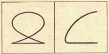
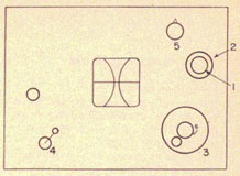
4. Turn crystal switch (PP) to ON. A "figure of eight" with the lower
half clipped will now he
observed on the "A" scope. If this figure is not observed:
5. Release lock and adjust (KK)-frequency
4-SC/SK-4
SC-SK RADAR
calibration so that a stationary figure of eight is observed. Lock control.
(See fig. 4 SC/SK-3.)
6. Turn crystal switch (PP) to OFF.
7. Crank (TT) so that 2,000 yards is observed on the first range counter.
Figure 4 SC/SK-3. Figure of eight determines when calibration pips are 2,000 yards apart.
8. Release lock on calibrate minimum (LL) and adjust position of range
step with (LL) so that
the top of the second marker just begins to drop. (See fig. 4 SC/SK-4.)
9. Crank (TT) so that counter reads 20,000 yards.
10. Release lock and adjust calibrate maximum (JJ) so that the top of the
eleventh marker
begins to drop.
11. Check the 2,000-yard setting and if it has changed, repeat step 9.
12. Check the 20,000-yard setting. If either (JJ) or (LL) is changed, it
affects the other. Keep
checking until no further adjustment is necessary; lock both controls.
13. Turn (CC) to RECEIVE.
This method of calibration differs from that given
in the instructional manual.
We use this method for three reasons:
a. To make the calibration and ranging uniform on SC-2 and SG, the center
of the range mark and the center of the target pip are used.
b. It is easier to range on the center of a pip than on the leading edge.
c. This introduction of error compensates for a range error on SC radars
when calibrated
against fire-control radar.
Calibrating the PPI.
The PPI unit must never be calibrated until the "A" scope has been
calibrated, since it is
dependent on the accuracy of the calibration of the "A" scope.
1. Turn the mark-IFF switch (1) to MARK.
2. Set the range selector (WW) to Range 2, and set the counter to 60
miles.
3. Set the PPI range selector (13) to Range 2.
4. With the antenna rotating rapidly, a circle will appear on the PPI
scope. Set calibrate control
(12) so that the inboard edge of the trace corresponds with the 60-mile
ring on the scope face.
5. Set the range counter to 30 miles and check the calibration. If the
internal calibration of the
set is correct, the PPI will be calibrated for all three range scales.
Figure 4 SC/SK-4. Pattern for calibrating minimum range on range 1.
4-SC/SK-5
RADAR OPERATOR'S MANUAL
Modification of PPI scope.
With the orange filter glass on the PPI, the range marks are so far from
the screen that errors of
several miles in range are possible because of parallax. The authorized
revision should be made,
whereby the filter glass is removed and the range lines made directly on
the face of the PPI
scope. This is (lone with a drafting compass and India ink as outlined
below.
1. Make a center for the drafting compass out of a small piece of
plastiglass in which you have
drilled a shallow hole to hold the compass point.
2. Secure this center to the center of the PPI scope with scotch tape.
3. Using the radii of the range circles on the filter, ink solid circles
on the scope face. To
facilitate direct reading of the 75-mile range scale, ink in two dashed
circles evenly spaced
between the solid circles.
Direct reading of the PPI on the 75-mile range scale is now easy and
accurate. The solid
circles are 15 miles apart. The dashed circles are 5 miles apart. The
range of any indication
may he read accurately to the nearest mile. Bearings are read by
bisecting the indication with
the cursor, and reading the bearing on the illuminated indicator.
OPERATIONAL TECHNIQUE
Tuning the receiver.
The technician will have the transmitter tuned for maximum power output
and it should not be
touched by the operators.
The preamplifier and receiver are also tuned by the technician, and only
slight adjustments
need he made by the operator. Care should be taken when tuning on a
bobbing echo that increase
in echo height results from tuning adjustments and not from bobbing of
the echo. Tune for
maximum results from tuning adjustments and not from bobbing of the echo.
Tune for maximum
echo height by going a little over and then a little under maximum.
Jockey back and forth
rapidly, and stop between the two points, a little over and a little
under, for optimum tuning. If
land echoes are available, they should be used for tuning. In any event,
all operators should
know the dial settings of the receiver for maximum echo height.
Long-range search.
Long-range search, so called, is essentially search for initial contacts
at any range. It will he
conducted either when there are no indications on the screen at
all, or when there are one or more target indications on the screen which
have been identified
and are of interest to the CIC watch officer only, as to their general
position. The CIC officer will
get most of the information he desires from his repeater scope, but a
rough plot should also he
kept. Readings every three minutes are usually sufficient for this plot.
The range scale used on the scopes will depend on the tactical situation.
In a carrier task force,
initial contact at the longest range is highly desirable. Two methods of
search are possible:
1. PPI scope on 200-mile range scale, and "A" scope on 75-mile range
scale, or
2. PPI scope on 75-mile range scale, and "A" scope on 375-mile range
scale.
When using the first method, most careful watch is made on the PPI scope
with occasional
search on the "A" scope. As the PPI is the less tiring scope to observe,
most operators prefer
this method.
The alternate method employs the closer watch of
the "A" scope with occasional search on the PPI scope. The advantage of
this method is that if a
contact is made within 75 miles, tracking may be begun immediately on the
PPI without changing scale.
If the task force has no air support, 75-mile warning of approaching
aircraft is sufficient, and
both scopes may be operated on the 75-mile range.
The receiver gain setting should he such as to give approximately 3/8-inch
of grass on the range
scope when the operator is giving his attention to the PPI scope. This
should he reduced to
between 1/16- and 1/8-inch when attention is given to the range scope.
The antenna should he rotated at a rate of approximately 1 1/2 revolutions
per minute. A plot
should be started on the first indication no matter how weak the signal.
On the next sweep of the
antenna, it may be stopped, the blip on the range scope studied to
determine composition, and the
plane challenged with IFF equipment. Normally this pause in continuous
rotation should not
take more than 15 seconds,
Searching over land.
If search must be made over land, target pips will be mixed with the land
pips. However, planes
will give echoes which bob up and down more rapidly and irregularly than
the land pips. Also,
the plane pip will move with respect to the land pips. When faced with
the problem of searching
over land, the antenna may he stopped for a few seconds to determine
whether the pip is actually
behaving as a plane echo or as a land echo. Bearings cannot be obtained
very accurately, but the
bearing of maximum swing of the
4-SC/SK-6
SC-SK RADAR
pip should be reported. Land masses may cause the pip to be higher on a
bearing a few degrees to
one side of the actual target bearing, and so maximum pip height may not
give the correct
indication-it is the maximum bounce that counts. The approximate bearings
secured are well
worth the effort to get them.
The operator must remember to keep searching. He should not find one
target and "camp on it"
from then on.
Multiple-target tracking.
Multiple-target tracking should be done exclusively on the PPI. In the
large majority of cases,
the 75-mile scale is the proper scale for multiple-target tracking. Rapid
ranges and bearings
may be accurately obtained on targets at from 10 to 80 miles, and a good
search for new targets
at ranges up to 80 miles is maintained. The antenna rotation speed should
be increased to 2 rpm,
and half of the targets reported for each revolution. Gain setting should
be for 3/8-inch of grass
on the range scope. All ranges and bearings are read from the PP 1.
Fighter-director tracking.
To a good operator, there s no essential difference between
multiple-target tracking and ID
tracking. With the antenna rotating at 2 rpm, reports can be given on the
intercept planes and
bogies at 30-second intervals, by reporting these targets on every
revolution of the antenna, if
desired by the fighter director officer. A good track can be kept on all
other targets by
reporting them every other revolution, giving one minute reports to the
plotter. Ranges and
bearings should come directly from the PPI operating on the 75-mile range
with the gain set
for 3/8-inch of grass on the range scope.
It may happen in certain instances during night attacks, that the gunnery
officer or assistant
gunnery officer will want to man the PPI himself. He will then be in a
position to direct AA fire
rapidly, and the information will not be delayed by going through CIC and
plotting.
Fire-control liaison.
Fire-control liaison may be conducted on the 75-mile range with normal
gain setting at about
ten miles, provided there are not many targets at the same range. With
several targets on
different bearings within ten miles, their echoes and side lobes will
ring the PPI scope and
cause too much confusion for fire-control coaching.
When the primary interest is fire-control coaching,
the PPI should be operated on the 20-mile range. The gain should he
reduced to an amount just
sufficient to keep the targets at the longest ranges appearing on the
scope. This will eliminate
some side lobes and reduce strength on all side lobes while holding
echoes from the main lobe on
the screen. This method of operation eliminates any chance of observing
planes coming in at
ranges greater than 20 miles, but is the most effective method when the
primary purpose is
fire-control coaching. At GQ, the standby operator can keep the fighter
director officer
informed of the general situation outside 20 miles by observing the range
scope and taking
ranges and bearings with continuous antenna rotation.
When the set is operating so as to read true bearings on the PPI, only
true bearings are put on a
repeater. If relative bearings are desired, the PPI relative-true switch
can be thrown to
RELATIVE, and the bearing indicator switch from RADAR to PPI. The bug is
then adjusted to read
the same on the outer dial as it is read on the yoke. Now, all bearings
from the PPI will be
relative, and the repeaters will read relative.
Composition.
Determination of composition of the target requires more operator
experience and closer
observation than any other phase of operation. Determination of
composition involves use of IFF
to determine whether a contact is friendly or not, and observation on
both range and PPI scopes
to determine number and size of planes in the group.
Large planes will have a low rate of fluctuation in echo amplitude, while
small planes will have
a high rate of fluctuation. The range scope is a better source of
information on composition than
the PPI scope. Upon making a contact, the antenna should he stopped on
the target, the gain
reduced to 1/16-inch grass on the "A" scope, and a thorough examination
of the echo made. The
number of planes can he estimated from the number of peaks on top of the
echo. The range at
which the target comes in is not conclusive proof of either its size or
altitude, but is a major
factor contributing to these estimations. The operator should give his
estimate of the
composition of every contact and this estimate should he substantiated or
corrected by visual
means whenever possible. The operator should then be notified of the
exact number, size,
formation, and altitude. Continuous repetition of this process is the
only means of improving the
operator's technique in determining composition.
Clouds, rain squalls, and ionized masses of air are readily detected on
the "A" scope, and are
usually easily disclosed on the PPI. Broad fuzzy pins, that
4-SC/SK-7
RADAR OPERATOR'S MANUAL
move slowly with occasional fading out, are characteristic of these
targets, although sharp
narrow pips have been observed. If identification is difficult by looking
at the pip, a plot should
be made to determine the course and speed. This should then be compared
with the course and
speed of the wind, which is the best check outside of actual
observation.
Any operator will learn to recognize land readily. However, most of them,
on looking at a group
of pips from land, will call the highest pip the highest peak of land as
"seen" by the radars. This
is wrong. The highest pip will be from that part of the land which has
the best reflecting
surface. The peak will be hard to identify if there is a range of
mountains behind it, or
mountains in the near vicinity at about the same range.
Jamming and deception.
There is no doubt that the enemy considers our radar an extremely
dangerous weapon, and
consequently it is only reasonable to expect him to try every means
possible to make it less
effective. He may use two tactics to do this: jamming and/or deception.
Every operator should
learn how to recognize these countermeasures, and expect them when in
combat zones.
When the enemy broadcasts radio signals intending that our radar receive
them, and they show a
confusing pattern on the screen, it is called jamming. Use of dummy
targets (tinfoil, kites,
balloons, etc.) is called deception. More precise definitions are
sometimes given, but these
are satisfactory for this discussion.
The SC radar can be jammed, and it will show echoes from the tinfoil the
enemy sometimes
throws out to confuse the operator. The operator should not become
alarmed when either of these
things happen.
If you were suddenly confronted with jamming, without previous
experience, it would appear
impossible to work through. However, it is not really that serious if the
following procedure is
carried out:
1. DF on the jamming.
2. Use available anti-jamming devices on the receiver when provided.
3. Try moving the gain control up and down.
4. Try changing the receiver local oscillator tuning.
5. Keep operating.
6. Report the type and bearing of jamming to CIC.
The first reason for obtaining a hearing on the jamming is to determine
whether or not it could be
accidental interference instead. Jamming will not only be directional,
but its true hearing will
not he changed by any sudden change in your ship's course. Interference
originating aboard your
own ship will either be non-directional and appear on all bearings, or
else it will always be on
some certain relative bearing regardless of changes in own ship's course.
Try moving the gain control up and down. This is probably one of the most
important
countermeasures that can he taken and the one most commonly overlooked
because of its
simplicity.
In most cases, except when effective noise modulated jamming is being
encountered, there is a
setting of the gain control with which it is possible to range on a
target in the presence of heavy
jamming. If there are several echoes on the same bearing, the best
setting for each echo is
different. Of course it is more difficult to obtain these ranges because
of the distortion of the
echo produced by jamming, but it is possible to obtain the desired
information. The extra effort
is worth while because the enemy would not be jamming unless he were
trying to conceal
something important.
Two general methods of using the gain control, both of which should be
tried, are as follows:
a. Reduce setting; this prevents overload of the radar receiver; echoes
are visible "riding on
top" of the jamming pattern.
b. Increase setting; this limits (or clips) jamming; echoes are visible
as a break in the base line.
Be sure to return the gain control to its normal setting when no jamming
is present, or when
the antenna is turned to an unjammed bearing.
Try changing receiver local oscillator tuning. When you change the
oscillator tuning, you lose
some of the height of the desired echo. However, if the jammer is not
exactly on your radar
frequency, there is a chance that you will detune the jamming signal more
than the echo signal.
Considerable improvement can sometimes be obtained this way. Try
"swinging" the oscillator
tuning dial in both directions to see which direction makes the greatest
improvement. Note the
correct setting of the oscillator dial so that it can he returned to its
normal position when no
jam is present, otherwise your radar will not give optimum results.
Even if the jamming is extremely effective, keep operating: do not turn
your radar off. Turning
your radar off informs the enemy that his jamming is effective, and makes
the radar completely
worthless. The effectiveness of the jamming may change from
4-SC/SK-8
SC-SK RADAR
time to time, and if you are persistent enough some information may be
obtainable.
Report the nature and bearing of the jamming to CIC. Recognizing the type
may be difficult
because non-synchronous patterns sometimes appear blurted beyond
recognition. Inasmuch as
knowledge of the jamming type* may possibly help identify the jammer in
some cases, this
information should be reported.
If the equipment is provided with an anti-jamming receiver, the jamming
may he reduced
sufficiently for reading targets without any detuning of the receiver.
Detuning should be a last
resort, and then should be done very carefully and cautiously, otherwise
all targets may be lost
and the equipment made completely ineffective. No set procedure is
offered for setting the
controls of the AJ receiver, except that they should be varied for
maximum readability through
jamming, the gain control coming first and then the AVC control followed
by Rej 1 and Rej 2.
Turn all AJ controls to the OFF or NORMAL position when no jamming is
being encountered.
Above all, never turn off the radar.
Even when jamming and/or deception is encountered, full 360 degree search must
be continued.
However, the antenna should be stopped for short intervals from time to
time in order to try
reading through the jamming (using the "A" scope). You also must be
prepared for diversionary
tactics, for the enemy may or may not use jamming and or deception to
divert your attention
from the bearing of the main attacking forces. This problem is simplified
when similar but
separate radars are used for reading through jamming and for searching.
PERFORMANCE
Ranges obtained on planes will vary greatly with the altitude of the
plane, because of fade areas
and the curvature of the earth. Large, high-flying planes have been
observed at 120 miles.
Average ranges on medium altitude planes are from 60 to 70 miles, and on
low-flying planes
from 20 to 40 miles on the SC-1, with better results on SC-2 and SK.
Ranges on surface targets will vary with antenna height, size of target,
and weather conditions.
In most cases, the ranges will be 6,000 to 10,000 yards shorter than
those obtained on the
same targets with surface-search gear.
* See Part 3, Defense Against Jamming and Deception.
Maximum reliable range.
SC-2 RADAR
Antenna 90 feet
BB, CV, CB, Large auxiliaries
37,800 yards
CA, CL, Medium auxiliaries
25,000 yards
DD, DE, DM, AV, PC, CG
17,000 yards
Submarines
5,900 yards
Large planes, PBM, PB2Y
132,000 yards
Small planes, 6F6, TBF, SB2C
72,500 yards
Land
142 miles
SK RADAR
Antenna 130 feet
BB, CV, CB, Large auxiliaries
51,500 yards
CA, CL, Medium auxiliaries
35,000 yards
DD, DE, DM, AV, PC
226,500 yards
Large planes
250,000 yards
Small planes
150,000 yards
Land
170 miles
Minimum range.
SC-1, SC-2, SK "A" scope
1,500 yards
PPI
20-mile range
2 1/2 miles
75-mile range
6 miles
Accuracy.
Reading directly from the PPI, range accuracy is 2,000 yards or better,
and bearing accuracy 4 degrees.
Bearing and range accuracies for the different ranges on the "A" scope
and PPI, when the
antenna is sweeping or stopped, are listed in the table below.
Ranges
Sweeping
Stopped
Range
Bearing
Range
Bearing
30,000 yards
1,000
3 degrees
200
5 degrees
20 miles
1/2 mile
3 degrees
5 degrees
75 miles
1 mile
3 degrees
1 1/2 mile
5 degrees
200 miles
2 miles
3 degrees
5 degrees
375 miles
5 miles
3 degrees
1 mile
5 degrees
Resolution.
Bearing
10 degrees
Range
500 yards
4-SC-SK/9
RADAR OPERATOR'S MANUAL
TROUBLES
There are in general, two methods of improper operation. One will result in complete disappearance of all target
indications from the screen. This
should be observed by the operator instantly, and measures should be
taken promptly to remedy
the trouble. The other is a general decrease in the ranges obtained.
Detection of this type of
failure requires much greater alertness on the part of the operator.
The jar of gunfire or surge currents may cause the overload relay in the
transmitter to kick
out, cutting off the transmitter. The red transmitter pilot light will go
out, all targets and the
transmitter pulse will disappear from the screen, and the sweeps on the
range and PPI scopes
will be jittery, because they are not receiving a synchronizing pulse
from the transmitter. The
operator should turn down the high voltage variac, press the overload
relay reset button, and
then
turn the high voltage variac back to its normal operating position.
Should the relay continue to
kick out, notify the maintenance man as to what occurred and what has
been done.
A gradual decrease in the operating efficiency of a set is harder to
detect. The operator must be
on the lookout for this at all times. One indication may be the point to
which the receiver gain
control must be turned to get the normal amount of grass. The best
indication is the ranges that
are being obtained on objects with which the operator is familiar, such
as ships in his group or
land in the vicinity. If poor results are being obtained, the operator
may try retuning the
receiver. If this does not help, the maintenance man should be notified.
The operator can greatly assist the maintenance man by giving a true and
accurate description of
what happened on the scope when the set went our of operation. This is
even more true of
intermittent troubles.
1. Plate current meter of modulation generator:
should read about 200.
2. Plate voltage meter of modulation generator:
should read about 500.
Figure 4 Mk. 3/Mk. 4-1. Main unit.
3. Load voltage: should be set to 120 at all times by
means of control No. 11. (A recent directive says 115, but do not set it
at 115 unless the set
has been adjusted for this.)
4. Magnetron plate current meter: should he set, to
read about 30 by controls 13 and 12.
5. Magnetron plate voltage meter: should be set to 12 (12,000 v.) by
means of control No. 12.
6. Magnetron filament voltage meter: should read 13.5. Can be seen by
looking through the wire
mesh on the front of the transmitter.
7. Frequency control of modulation generator: adjusted by technician.
8. Radio dial light dimmer: controls the brightness of the illuminated
dial on the receiver.
9. Receiver tuning control.
10. Receiver sensitivity control:
11. Load voltage control.
12. Magnetron plate voltage control.
13. Field control: adjusts plate current to the magnetron.
14. Remote-local switch: determines whether the receiver sensitivity is
controlled from the
main unit by control No. 10, or whether the sensitivity is controlled by
the receiver
sensitivity knob on the range scope.
15. Main off-on switch or line switch.
16. Plate off-on switch.
17. Dim-bright switch: controls brightness of the pilot lights on the
face of the main unit.
18. Mon jack: used in tuning up the receiver.
19. Audio jack: used to obtain a synchronizing voltage when tuning up the
receiver.
20. Screw lock for 21.
21. Magnetron filament voltage adjustment.
Control and indicator unit (range scope).
1. Intensity control: controls the brightness of the picture on the scope.
2. Image spread control: controls the size of the notch and expanded
sweep.
3. Receiver sensitivity control: controls height of the grass and echoes.
4. Focus control: focuses the image on the face of the scope.
5. Sweep gain control: controls the length of the sweep. Should be
completely clockwise.
4-Mk. 3/Mt. 4-2
MARK 3 AND MARK 4 RADAR
6. Lobing on-off switch: turns lobing motor on or off.
7. Transmitter standby switch: turns the transmitter on or off. Used as a
stand-by switch.
8. Pilot light dim-bright switch: (to be replaced by an A.G.C, switch.)
Some sets have an
anti-jamming switch above control 2.
Figure 4 Mk. 3/Mk. 4-2. Control and indicator unit.
Range unit.
1. Inner knurled nut: locks friction drive between
the range knob, No. 3, and the electrical system controlling position of
pips on the lace of the scope.
2. Outer knurled nut: moves images across the scope.
3. Range knob: moves images across the scope.
4. Pilot light bright-dim switch.
5. Dial light bright-dim control.
6. Signal button.
Figure 4 Mk. 3/Mk. 4-3. Range unit.
Train or elevation indicator.
1. Intensity control: controls the brightness of the image.
2. Image spacer control: move one sweep with relation to the other.
3. Sweep expansion control: opens or contracts the two steps.
Figure 4 Mk. 3/Mk. 4-4. Train or elevation indicator.
4-Mk. 3/Mk. 4-3
RADAR OPERATOR'S MANUAL
4. Focus control: focuses the image.
5. Pilot bright-dim switch.
TURNING ON AND OFF
Turning on the main unit.
1. Make sure main off-on switch (15) and plate off-on switch (16) are
turned OFF and the plate
voltage control (12) is turned completely counterclockwise (against the
stop).
2. Turn on line transformer switch (mounted somewhere on the bulkhead).
3. Check magnetic controller switches (if any).
4. Turn on stand-by rotary switch near C and I Unit (when installed).
5. Turn on transmitter stand-by switch (7) on C and I Unit.
6. Turn on the main off-on switch (15). Before turning on anything else,
listen to see if the
blower fan cooling the magnetron starts running as soon as the main
switch is thrown. The load
voltage meter (3) should go to 120 volts. Adjust it to this value by
means of the toad voltage
control (it) and make sure it stays at this value. The plate voltage
meter (2) in the modulation
generator will swing to the right of the scale and slowly come down to
about 500 volts. The plate
current meter (1) on the modulation generator will start at zero and
after a few seconds will
slowly come up to about 200 milliamperes. When this meter reaches a
stable value, the 1,639
c/s note will be heard coming from the modulation generator.
7. Turn on the plate off-on switch (16). Wait at
least 5 minutes before turning up the plate voltage. When the plate
switch is turned on, the two
tubes located in the front of the high voltage rectifier light up.
8. After 5 minutes have elapsed, slowly turn up (clockwise) the plate
voltage control (12)
until the plate voltage meter (5) reads 12 kilovolts. Make sure the plate
current meter (4)
does not go above 30 milliamperes. Adjust the held control (13) until the
plate current meter
(4) reads 30 milliamperes (30 milliamperes is an average value, it will
he different on some
sets). The plate current and plate voltage are not independent. Any
change affecting one will
affect the other. Thus both plate voltage control (12) and held control
(13) must be moved
together.
9. Check filament voltage meter (6) to see if 13.5 volts are applied to
the filament of the
magnetron.
If not, adjust to this value by magnetron filament
voltage adjustment (21).
10. Check to see if the remote-local switch (14) is on REMOTE. The main
unit is now turned on
and the set is all ready to operate. It is a good policy to tune up the
receiver upon turning on the
set, and about once every hour thereafter-more frequently if the set is
subjected to serious
vibration or temperature change.
Turning off the main unit.
1. Turn the plate voltage control (12) counterclockwise slowly until it
hits the stop.
2. Turn plate on-off switch (16) to OFF.
3. Turn main off-on switch (15) to OFF.
4. Turn bulkhead switches off.
Every time the main unit is turned on from a cold start, the wear on the
set is equivalent to
three hours steady running of the set. Thus, if the set is to be turned
off and on eight times a day
it would be more profitable to let the set run continuously.
Another even more important consideration in this respect is that it
requires approximately
three hours running before the set is warmed up sufficiently for most
accurate operation. If the
modulation generator has a red light at the top of the front panel which
flashes off and on, it will
take a much shorter time to warm up (approximately one hour).
When turning on any of the units in the director, the stand-by bulkhead switch, which turns on the scopes, must be turned ON-reverse procedure, for
securing the gear.
Turning on the control and indicator (C&I) unit.
1. Turn sweep gain control (5) completely clockwise.
2. Turn intensity control (1) clockwise until an indication is observed
on the face of the scope.
3. Focus the trace by means of the focus control (4). Note: For each
setting of the intensity
control there is a distinct setting of the focus control. Be careful not
to make the trace too
bright. The trace should never be so bright that the return trace can be
seen over the notch.
(This undesirable condition is apparent when the notch is fully expanded.
It makes the notch
look like a box.)
4. Turn the image spread control (2) completely counterclockwise.
4-Mk. 3/Mk. 4-4
MARK 3 AND MARK 4 RADAR
5. Turn the receiver sensitivity control (3) clockwise until the grass is
about a half-inch high.
6. Make your "zero set" and continue to check it as frequently as
possible while operating the set.
7. Turn the transmitter switch (7) on. The instant this switch is turned
on the set is "on the
air." The main frame should never be turned off and the transmitter
should be controlled by
means of this switch; the switch is designed to do this, If it is found
that fuses are blown by
doing this, it is an indication that some element is not functioning
properly and should be
promptly remedied.
8. The lobing motor should he turned on only when using the set. It
should remain on while
searching for targets and while tracking. But remember, whenever the set
is not actually being
used, turn the lobing motor off.
Turning off the control and indicator unit.
1. Turn off lobing motor (6).
2. Turn off transmitter (7).
3. Turn intensity control completely counterclockwise (1).
Turning on the trainer's and pointer's scopes.
1. Turn the image spacer control (2) completely clockwise.
2. Turn the sweep expansion control (3) completely clockwise.
3. Make sure the range scope operator has the lobing motor turned on.
4. Turn the intensity control (1) clockwise until two horizontal lines
appear on the scope. These
lines will not be straight, but will be slightly curved.
5. Focus the traces by means of the focus control (4). It is important
that the sweep should be
just bright enough to see and no brighter. It should be focused to a
fine, sharp line.
6. The image spacer (2) and the sweep expansion controls (3) should now
be turned
counterclockwise until the sweeps are about 1/4 inch wide and separated by
about 1/8 inch.
Turning off the trainer's and pointer's scopes.
1. Turn the intensity control (1) completely counterclockwise.
Tuning the receiver.
1. Connect a patch cord to the vertical input terminals of the test scope. The BLACK side is
connected to the grounded side which on RCA scopes is marked with a
zero. The RED, or high
side is connected to the top of the two vertical terminals which are
marked high. Plug this cord
into the right hand plug of the four jacks in the radar receiver panel;
this is marked mon (18).
2. Connect another patch cord to the sync terminals. Connect the BLACK to
the ground terminal
and the RED to the high terminal. Sometimes the red and black markers
have become obliterated.
They can be readily distinguished, since the BLACK side, or ground side,
is the outer conductor
of the cable and probably will have no insulation on it. The RED side, or
high side, is the inner
conductor and will be insulated. This cable is plugged into the audio
jack (19) in the modulation
generator panel.
3. Turn the vertical and horizontal centering controls on the test scope
to mid-position. Turn
vertical amplifier knob off. Turn the horizontal amplifier knob to EXT.
Turn the vertical and
horizontal gain controls to zero. Turn the range to 550-4,500 (for RCA
155 A or B) or 700-7,000 (for RCA 155 C). Turn the frequency to zero. Turn the sync knob to zero.
4. Plug in the scope to 110 volts AC and turn the intensity clockwise
until a click is heard.
5. Wait for about one minute and then turn the intensity control
clockwise until a spot is
observed on the screen. Be careful that this spot does not become bright.
Turn the horizontal
gain control clockwise until a horizontal line covers the scope with a
small margin left over at
each side. Focus this line by means of the focus control. Adjust the
horizontal and vertical
centering controls until one line is centered on the face of the scope.
6. Turn the vertical amplifier to the ON position. Increase the vertical
gain control until the
pattern occupies about 10 divisions on the scope.
7. Turn the frequency control clockwise slowly. It will be noticed that
images will be formed on
the face of the scope with the pips displaced downward from the
horizontal sweep. As the control
is advanced, first, four pips will be formed, then three, then two, and
finally one. When one
image is formed, it will be found that it will be almost impossible to
make that pip appear
stationary on the scope. Get it as steady as possible, then slightly turn
the sync control
clockwise, and it will be found that the image on the scope will
4-MR. 3/Mk. 4-5
RADAR OPERATOR'S MANUAL
lock in and cease to move, The image thus formed will be the same picture
that is on the C and I
scope in the director, except there will be no notch and there will be no
expanded portion of the
sweep. It should be noted here, that the operator might find the actual
tuning procedure, which
is about to be described, easier if he stops the image on the screen with
two pips on it rather
than one. This is largely a matter of preference, By adjusting the
horizontal gain and the
horizontal centering knobs, the operator can make the two pips line up
with the divisions on the
graduated face of the scope. By counting the number of divisions between
the pips, and realizing
that this distance corresponds to 100,000 yards, it is possible for him
to estimate roughly the
distance to any target.
8. Turn the remote-local switch (14) to LOCAL, and the height of the
grass and the echoes may
be controlled by the receiver sensitivity control (10), located on the
front panel of the
receiver. Turn the receiver turning control (9) back and forth until the
pips come to a
maximum, and decrease on each side of the maximum point. By going back
and forth over this
point several times, it is possible to find accurately the position of
the knob which gives
maximum echoes on the test scope. It is best to tune on small echoes and
get them as big as
possible.
Note. For precise tuning, it is absolutely necessary that no one move
the antenna while the
receiver is being tuned, either in train or elevation. It is also highly
desirable that the echo
used to tune the set be a steady pip from a land target. This is the only
tuning adjustment the
operator need know. Further tuning requires the more extensive knowledge
of the maintenance man.
CALIBRATION
Range zero set.
1. To show accurate ranges, it is necessary that the range dial be
accurately calibrated so that
zero range on the range dial corresponds to zero range on the scope. Turn
the grass to the height
usually used in operation (about half an inch), and turn the image spacer
knob (2) completely
clockwise.
2. Turn the range dial to the zero set given by the technician. It is a
minus value of range,
usually about minus 200 yards, at which the range dial is set, (A value
of minus 200 yards is
the same as a range of 99,800.)
3. Loosen the inner knurled nut (1) located above the range crank,
4. Turn the outer knurled nut (2), and move the image across the scope
until the left-hand edge
of the transmitted pulse coincides with the left-hand edge of the notch.
Adjust this nut until the
left-hand edge of the notch falls half-way down to the bottom of the
notch.
Figure 4 Mk. 3/Mk. 4-5. Transmitter pulse position for correct zero set.
5. Check to see if the range dial is at the zero set. and then carefully
tighten the smaller knurled
nut with the right hand, while holding the larger nut with the left hand
to prevent it from
turning.
6. Crank the pulse out of the notch, then crank it
back to the position described in step 4 above, and check to see if the
zero set has slipped while
tightening up the smaller nut. If it has slipped, repeat the above
procedure until the correct
setting is obtained.
Note: The above procedure should be practiced until an accurate zero set
can be made very
rapidly. During the first half-hour after the radar has been turned on
from completely off, the
zero setting should he checked at least as frequently as once every two
minutes if accurate
ranges are necessary during this time. After this time has elapsed, the
zero setting may be
checked less frequently. After three hours, the zero setting may be
checked about once every
half-hour, and always before each firing run in gunnery practice or
battle, if practicable.
4-Mk. 3/Mk. 4-6
MARK 3 AND MARK 4 RADAR
Double range echo method of obtaining zero set.
(See Part 1. General Radar Principles.)
1. Train on another ship-the larger the better, on a course parallel to
your ship and not more
than 2,000 yards from it. (Between large ships, greater distances may be
used.)
2. Start getting ranges on the other ship. It is important that the
pointer and trainer remain
right on the target during the following procedure.
3. If the other ship is close enough, two pips will be observed on the
range scope. The closest pip
will be saturated and the second pip will probably be quite small. The
second pip will be at
approximately twice the range of the first pip. (See fig. 4 Mk. 3/Mk. 4-6.)
Figure 4 Mk. 3/Mk. 4-6. Double range echo.
4. The first pip is placed in the notch, and its range is noted. Let us
say its range is 1,700
yards. Then the second small pip is placed in the notch, and its range is
noted. Let us suppose its
range is 3,200 yards. The difference between these two readings gives the
accurate range
between the two pips. In this case the range would be 1,500 yards. The
range to the double echo
should be just twice the range to the first echo, since the pulse has had
to travel just twice the
distance in forming the double echo that it traveled to the first echo.
Therefore, the total
distance traveled by the pulse in forming the double echo was 3,000
yards, and the distance to
the first echo must be half that distance, or equal to the
distance between the first and second echoes, namely 1,500 yards.
5. The first pip is then placed in the notch and the range dial is set to
the difference between the
ranges of the first and second pips (in this case 1,500 yards), by means
of the zero adjustment
nuts.
6. After securing the zero adjustment nuts, the transmitted pulse is
cranked back to the notch
and placed as though making a zero set. The minus zero set is noted when
the transmitted pulse
is as shown in figure 4 Mk. 3/Mk. 4-5.
This zero set should be written down in a conspicuous place near the
range unit, as it is the zero
set that should be used. Steps 4, 5 and 6 should be executed as quickly
as possible and repeated
several times until consistent results are obtained. Occasionally, there
will be two pips where
the double echo should appear, and the range operator may not know which
is the true double
echo. One of these pips, however, will be clear and the other foggy. The
clear one will be the
double echo. The reason for this is, that if you are on the target the
pip from the target will be
clear and not foggy. A foggy target would indicate another ship, sore
debris, or another
extraneous target which is off the line of sight. Finding the zero set
should be done only after the
set has been on at least three hours, and is thoroughly warmed up. This
is only one method of
obtaining your zero set. Other methods are described in BuOrd Pamphlet
No. 657.
*Train and elevation calibration.
1. Alignments of the radar antenna with the optics is an easy matter. The
trainer and pointer
have merely to look through their telescopes when their pips are matched,
to see if their cross-hairs cut the target. During an exercise using full radar control, the
control officer can
determine if the radar is aligned with the optics, by looking through his
telescope when the
crew gives the word that they are on the target.
2. Level and cross level should always he cut in when aligning the
antenna.
3. To align the antenna in train, two men are placed on top of the
director with wrenches to
loosen the securing bolts, and move the adjusting screws holding the
antenna. The trainer and
painter
* Note: This is a technician or Navy Yard job.
4-Mk. 3/Mk. 4-7
RADAR OPERATOR'S MANUAL
stay on a small, distant target with their optics. The maintenance man
watches the pips on the
trainer's scope, and directs the men adjusting the antenna to move it to
the right or left, as
indicated by the pips on the trainer's scope. When the pips are even, the
antenna is locked in
place.
4. The antenna should never be checked for elevation accuracy at angles
less than 15 degrees. If it is
found to be off, it is realigned by training optically on a plane flying
directly to the ship, and
passing over the ship. The maintenance man should adjust the microcoupler
on the antenna
shaft, while watching the pointer's scope, until the pips on the
pointer's scope are equal.
5. For more details see BuOrd Pamphlet No, 657.
OPERATIONAL TECHNIQUE
The range operator.
The range operator is the keyman of the FD team. Upon his shoulders rests
the responsibility of
supplying pips of the proper size to the trainer and pointer. It is up to
him to select the
particular target the gunnery officer may designate. He must also be able
to tell what type of
target a certain pip indicates, if a ship, the approximate size; if a
plane, its size; if a number of
planes, the approximate number in the flight. He must be able to
distinguish the pip presented
by a submarine from the water return which tends to confuse it. He must
be ever alert to detect
even the weakest echoes, and he prepared to get his team on them before
they disappear.
The two greatest responsibilities of the range operator are: (1) to keep
the pip in the notch, and (2)
never to let it saturate (flatten on top due to too much receiver
sensitivity). The pip must be
kept in the center of the notch so that the pip appears even on the
pointer's and trainer's scopes.
If the pip saturates on the range scope, it will saturate on the
trainer's and pointer's scopes,
thus preventing them from knowing which way to train or elevate.
One of the range operator's hands should always he on the range knob.
When he wants to change
range quickly, he should turn the range wheel with the small crank on it.
For fine adjustment of
range, such as keeping the pip in the notch, the operator should grasp
the wheel with his hand
and not use the crank. Usually this will be the right hand, but in some
installations it may
require the left.
The opposite hand (usually the left), should always be resting on the top
of the range scope. The
range operator will find that after once setting up the scope correctly,
there are only two knobs
that require further adjusting. but those two knobs will have to be
adjusted frequently. These
are the image spread (2) control, and the receiver sensitivity (3)
control. The receiver
sensitivity must be readjusted as often as necessary, to prevent
saturation of the pips seen on
the pointer's and trainer's scopes. He should make all adjustments on the
range scope with his
left hand (or with his right if his left hand is on the range knob). He
must know the position of
all controls so well that he can make adjustments to the scope without
groping for the knob or
taking his eyes from the scope.
Figure 4 Mt. 3/Mk. 4-7. Pips on trainer's or pointer's scope.
The trainer and the pointer.
The trainer trains toward the smaller of the two pips. (fig. 4 Mk. 3/Mk. 4-7, train left.)
The pointer elevates if his left pip is lower. (fig. 4 Mk. 3/Mk. 4-7, elevate.)
A rule to follow is the Three L Rule. For the
trainer: left, low, left; meaning if his left pip is low,
train to the left. For the pointer: left, low, lift; meaning if his left
pip is low, lift or elevate the
antenna.
Some pointers think of the left pip on their scope as an indication of
the position angle of the
antenna. If the left pip is low (in relation to the right pip, of
Course), the antenna is pointed
below the target. If the left pip is high, the antenna is pointed above
the target. This is a good
way to tell the position angle of the antenna.
4-Mk. 3/Mk. 4-8
MARK 3 AND MARK 4 RADAR
When the pips are of the same height, the pointer and the trainer say.
mark," or "on train," or
"on point." Occasionally you will notice that the pips will act in
reverse, in other words, when
you train or point toward the lower pip, it will get lower rather than
higher. This indicates that
you have a minor lobe contact. The target actually bears 15 degrees to 20 degrees to
the left or right of this.
Sometimes the trainer will be able to match up two pips, but no pips will
show on the pointer's
scope. This can be caused by minor lobes again, and the trainer should
train back and forth until
the pointer and the trainer both can see two pips. The angle between the
minor lobes and the
main lobe is 15 degrees to 20 degrees.
Below 12 degrees of elevation, the ED cannot be relied upon to give accurate
position angles. With
surface targets we know what the position angle is, and so are not
concerned about the inability
of the ED to give an accurate position angle. In train there is not this
inaccuracy.
Searching with bearings and ranges given.
The approximate bearing and range will be given
to the operator by CIC. The approximate range is placed on the range dial.
When the director is
trained to the approximate bearing, the lobing motor should be turned on,
and a search begun
through a small angle (15 degrees) for the target. The elevation angle should be
varied from zero to
about 10 degrees. It is most important that the image spread knob (2) be turned
completely
counterclockwise. The range operator must be extremely alert to see any
echo that may appear
along the length of the sweep. He should never allow his gaze to
concentrate on one portion of the
sweep for too long a time. Echoes frequently appear as a small, straight
line, no higher than the
grass, and the operator must be quick to notice them. Turning the range
knob back and forth
slightly helps somewhat, because echoes which ordinarily would be hard to
distinguish from the
grass become more readily discernible, appearing as small, bright lines,
moving back and forth
in the grass. The selector switch should not be on RADAR RANGE when doing
this.
As soon as the range operator sees the target he should call out "mark,"
or "hold train and point,"
so that the pointer and trainer will stop searching. Then, opening the
notch with one hand, and
turning the range knob with the other, he should rapidly bring the target
into the notch at no
time losing sight of the target. If the target is at a great range, it
will probably disappear by the
time the operator has it
in the notch. To help speed op the process of getting the pip in the notch,
the operator should have
previously cranked onto his range dial the range given by the search
gear. If the target should
disappear, close the notch, hold the train and elevation and turn the
range knob back and forth.
Soon the pip will show up again, and this time the operator will be able
to get it into the notch;
the pointer and the trainer will also get a fix or an indication of which
way to train or elevate
before it disappears. This process should be continued patiently. If the
pip is clear the range
operator knows that the pointer and or trainer are on target. If the pip
is cloudy, the trainer
and pointer are off the target. On some targets, however, such as a
flight of planes, it will be
impossible to get a clear pip.
Searching when no bearings or ranges are given by the search-radar.
In searching, when bearing and range are not given by the search radar,
practically the same
method is used as was described in the preceding section. The only
difference is in the range
operator's use of the sweep gain control. While searching, when you do
not know that there are
any targets, the sweep gain control should be turned counterclockwise
until the trace occupies
only about three inches. Targets can still be seen with ease, and this
method possesses the
advantage that the operator will be able to keep the whole sweep under
his eyes at once. An
experienced operator will not have to do this as often as an
inexperienced operator, since the
experienced man can watch alertly the greater trace as easily as the
inexperienced man can
watch the shorter sweep.
It seems to be the current practice, to keep the lobing motor turned off
at all times, except when
actually tracking a target. The only valid reason for this is that it
saves the lobing motor from
excessive wear. This admittedly is important since the lobing motor and
cam assemblies are one
of the weakest units of the Mark 3 and Mark 4 radars. They are located
in a place where it is
difficult to work and repairing them properly is a tedious job.
There are many in the held, however, who feel, that the benefits to be
derived from operation of
the lobing motor for searching outweigh the disadvantages. The greatest
benefit of using lobing
while searching is that it causes the beam width to increase from 9 degrees, the
normal width of the
beam, to 15 degrees, the width of the radiation pattern between half-power
points with the lobing on.
This increased coverage accompanied by no loss in power, since actually
4-Mk. 3/Mk. 4-9
RADAR OPERATOR'S MANUAL
we are simply waving the same beam back and forth in front of the director.
It is easier to spot a
target quickly with the increased beam width than it would be if you had
only the one 9 degree beam.
Another reason for keeping the lobing motor on while searching, is that,
once a target is picked
up, and the trainer and pointer get on it by using optics, the C and I
operator will have no need
to turn the lobing motor on. He probably could read ranges under this
condition, but let us
suppose the target was suddenly obscured from view for some reason, as
the laying of a smoke
screen, or the sudden appearance of a rain squall. The trainer and
pointer would immediately
turn to their radar to track the target, and it might take some time to
determine that their
lobing motor was not on, and another period of time to line up their
scopes. In the excitement of
battle, working under nervous tension, such a delay might easily be
prolonged. Any delay,
however slight, at such a time, might very well change the outcome of a
battle. So if such a delay
can be eliminated, even at the expense of giving the maintenance men
additional work, it should
be done, and the lobing motor should he left on.
When the lobing motor is turned off, the beam, which was being swung in
four distinct
positions, gradually comes to a stop. It might be pointed up into the air
or down into the sea. It
might be pointed to the right or left. There is absolutely no accurate
method of telling just
where the beam is pointing. In any case, it never comes to rest pointing
along the line of sight.
Thus you might be searching for a ship with the beam pointing up into the
air. However, if you
turn your lobing motor on when searching your beam will be swung in all
four positions, and
you can always be sure you will not miss your target because you know
your beam is pointed in
the right direction.
Tracking.
Gradually the pip will become strong enough that it may he continuously
tracked. When this
occurs, the computer may be switched in, if full radar control is
desired. As soon as the target is
close enough to appear in the pointers and trainer's telescopes, the
optical rangefinder should
notify the control officer, and the trainer and pointer should switch
over to their optics. Radar
ranges should be used whenever possible, since they are more accurate
than optical ranges.
Furthermore, radar will give the range to the target continuously,
whereas most stereo-rangefinders have to put their reticules back and forth over
the target, thus not transmitting ranges continuously. Accordingly, a
set-up on the director can
be made more quickly by using radar ranges and rate control on the
director than by any other
means.
After the range operator has picked up the target and told the pointer
and trainer to "hold train
and point," he cranks the pip into the notch as described above. When it
is in the notch, he says
loudly, "on target." This indicates to the trainer and pointer that he
has a pip in the notch and
they accordingly look closely for it. When they have their pips matched
up, they each say
"mark." They continue saying "mark" whenever their pips are matched, and
the range operator
continues to say "on target," whenever he has the pip in the notch and
the pointer and trainer
are still using their radar.
Another good method is for the range operator to say "on range"; the
trainer, "on train"; and the
pointer, "on point."
The control officer will instruct the range operator as to the procedure
and doctrine of pushing
the range button. This range button is located in the center of the range
knob and, when pushed,
signals plot that the range is on at that instant. It also activates the
range rate mechanism.
Spotting.
It is possible to see the shells leave the guns of your ship and follow
them for quite a distance on
the scope. Sometimes they look like "mice running under a carpet."
Usually, they appear as
distinct pips and move across the scope. You can also see shells from the
enemy coming toward
you on the screen. That should not prove too disconcerting, since they
could miss your ship by
quite a distance and still appear to be coming toward it,
The range operator has the additional function of spotting misses. This
is done by estimating the
distance from the target's pip to the pip produced by the miss. The notch
should be completely
expanded. The width of the notch and the width of the expanded portion of
the sweep should be
determined for the operator's set. This can be accomplished by cranking
an echo, or the leading
edge of the transmitted pulse across the notch or sweep, and noting how
much range was covered
on the range dial. The notch is generally about 600 yards wide, and the
expanded portion of the
sweep about 6,000 yards. If the set is in perfect operating condition,
the notch should remain in
the center of the C and I scope. You can estimate the spot by mentally
comparing the distance
from the target to the splash with the
4-Mk. 3/Mk. 4-10
MARK 3 AND MARK 4 RADAR
width of the notch. Some ships have installed a scotch tape scale on the
face of the range scope to
aid in spotting.
Determining composition.
Skill in identifying targets by means of their pips is largely developed
by experience. Aircraft
pips flutter up and down vigorously. Their bearing, range, and elevation
change rapidly. Clouds
and atmospheric conditions which sometimes give echoes similar to planes
are easily
distinguished by means of their slow change in bearing, range, and
elevation. Sea-return, which
also looks like planes, usually appears within 2,000 yards, and it is
impossible to obtain a
bearing on it. Two planes flying together produce a beating effect, and
their pip will bounce up
and down with some regularity. A group of planes will produce a large
echo which is never clear
inside. They can be picked up by a good operator at 90,000 yards if they
are high enough, and
the set is operating properly.
The range to surface targets is limited by the horizon. Ships produce
pips which will fluctuate
up and down rather slowly; the larger the ship, the slower the
fluctuation of the pip. They
change range and bearing (but not elevation) slowly. Land targets are
steady and strong.
Sometimes land echoes will fluctuate like planes or ships. Good judgment
together with
experience will enable you to identify such pips as echoes from land.
Satisfactory results cannot
always be obtained when tracking a sleeve, for the sleeves in current use
give echoes too weak to
be used properly.
If the radar team must be coached on to the target by means of optics,
they are knowingly
passing up one of the greatest advantages we possess over the enemy.
Radar should always pick
up the target when it is far beyond optical ranges. Remember, that your
skill as an operator
will increase with practice. When you are able to distinguish an SBD from
a TBF by the
difference in their pips, you have really accomplished something.
Anti-jamming technique.
Oilier radars may produce interference on the range scope. This, as well
as electrical faults in
the set itself, can produce effects which might be called jamming by the
inexperienced operator.
If the interference is caused by the transmitted pulse from another radar
set, an occasional pip
will move across the screen in either direction. Effects which occur on
all bearings or on the
same relative bearing should also be
classified as unintentional interference rather than jamming.
If the range scope seems to be jammed, report the fact immediately to the
control officer, and
also to the maintenance man. Continue to try to work through the jamming.
Turning your lobing
off may help. Sometimes the narrower antenna beam resulting when lobing
is off will enable the
operator to direct the beam on the target alone, and not on the target
plus the jammer, as might
well happen with lobing on, and double the area being covered. Thus the
operator might be able
to range on the target, but he would have to turn the lobing on again to
get a bearing. Vary your
receiver sensitivity control (3) carefully to determine the optimum
setting. Return the
receiver sensitivity control to its normal setting when the jamming
ceases, or when operating
on unjammed bearings. This is important, because targets may sometimes be
visible at low
sensitivity control settings in the presence of jamming, but completely
absent at the same
sensitivity control setting when the jamming ceases.
It is possible to train on the jamming station by simply matching the
height of the jamming in
the trainers pips. Remember, that the jamming will probably be much
stronger than most
echoes, and will tend to produce saturation signals. Therefore, when
matching pips in jamming
be sure that the gain control is turned down sufficiently, otherwise it
will be difficult to pip
match. Two ships can thus get a fix on the jammer. The pointer should
also match the jamming
on his scope. Remember though, minor lobes are much more important when
being affected by a
jamming signal than they normally are. So be very careful when using this
method that you do
not get on a minor lobe when matching up the height of the jamming on the
two scopes.
Rotate the antenna to determine whether the jammer and the target are on the same bearing. If they are not on the same
bearing, a pointing and
training error of several degrees or more is to be expected, even if it
is apparently possible to
match pips. Report this to CIC. When the target and jammer are less than
5 degrees apart in bearing it
will be difficult to determine whether the jammer is on or off the target
bearing. The accuracy
of range information is not seriously affected by jamming on any bearing,
but it will, of course,
be more difficult to obtain. It will be found that the pip matching
scopes are more difficult to
interpret than the range scope when jamming is encountered.
The maintenance man can change the frequency of
4-Mk. 3/Mk. 4-11
RADAR OPERATOR'S MANUAL
the transmitter slightly by varying the field control, and the plate
voltage of the magnetron, or
by varying the duplexer tuning. This method is valuable, but the jammer
may shift to your new
frequency. Changing the receiver local oscillator tuning at the main
frame may also be of some
assistance.
As pointed out previously, it is of the greatest importance to keep
trying to work through the
jamming. The jammer will have to stop operating occasionally to check
your frequency. in order
to see if it has been changed. The second he stops jamming, obtain ranges
and bearings
(sometimes position angles), on the target. You must keep alert in order
to get on the target
almost instantly.
Some sets have an anti-jamming modification installed in the C and I
unit. Turning this device
on will sometimes improve the C and I scope. Always remember to cut all
anti-jamming devices
out of the circuit when no jamming is present.
The official policy is to keep your transmitter on at all times,
attempting to work through the
jammer, even though at first glance it may seem impossible to do so.
Perseverance and patience
will be rewarded many times by your being able to range on the target.
Because the echoes
increase more rapidly with decreasing range than the jamming signal
increases, it may he
possible to suddenly see the pip from a closing target. This is another
reason for leaving the
transmitter on at all times.
Never give up hope. Look for small discontinuities in the jamming, they
might well be echoes.
The British have shown that good jamming is extremely difficult to carry
out successfully. So
keep trying to work through the jamming, be patient, and above all do not
get excited. A cool
head is the best anti-jamming device ever discovered.
RELIABLE RANGES OF MARK 3 RADAR
75' Antenna height
125' Antenna height
Type
Without preamp.
With preamp.
Without preamp.
With preamp.
Large ships-(BB, CV, Large Aux.)
17,500
20,000
20,500
27,000
Medium ships-(CA, CL, Med. Aux.)
15,000
17,000
18,500
25,500
Small ships-(DD, DM, AD, PC, etc.)
11,500
13,000
13,500
18,000
Submarine (surfaced)
4,500
--
10,000
7,000
Submarine (periscope)
2,500
--
--
--
Large planes-(PBM, PBY, PB2Y, etc.)
25,500
20,500
23,000
36,500
Small planes-(SOC, OS2U, SBD, F4F, etc.)
14,000
8,000
15,000
--
RELIABLE RANGES OF MARK 4 RADAR
75' Antenna height
125' Antenna height
Type
Without preamp.
With preamp.
Without preamp.
With preamp.
Type
Without preamp.
With preamp.
Without preamp.
With preamp.
Large ships
16,000
18,500
15,500
26,000
Medium ships
12,000
15,500
16,000
25,000
Small ships
9,000
11,000
11,000
18,000
Submarine (surfaced)
3,500
--
7,000
--
Submarine (periscope)
--
--
4,000
--
Large planes
22,500
16,000
21,000
47,000
Small planes
13,500
13,500
13,000
23,500
4-Mk. 3/Mk. 4-12
MARK 3 AND MARK 4 RADAR
PERFORMANCE
Maximum reliable ranges.
The tables on the opposite page show the maximum reliable ranges of the
Mark 3 and Mark 4
Radar. The figures given are the averages of many ships reporting. These
data are taken from
BuShips' publications.
A good crew with well-maintained sets should he aide to get considerably
better results than
these.
Minimum ranges.
On ship targets the minimum range is 800-1,000 yards. The minimum range
on aircraft is
1,100-1,700 yards.
Accuracy characteristics.
The following table is taken from BuOrd Pamphlet No. 657, and shows the
accuracy-resolution
characteristics of the Mark 3 and Mark 4 Radar, using three different
antennas.
Resolution.
The range resolution of the Mark 3 and the Mark 4 is 400 yards. The
bearing resolution of the
Mark 3 (3' x 12' antenna) is 5 degrees. The bearing resolution of the Mark 4 is
10 degrees.
These are important figures, and they should be kept in mind at all
times. If a target is greater
than 400 yards offshore, a Mark 3 or Mark 4 will distinguish the target
from the land as long
as the line of sight to the target is perpendicular to the shore line. In
this ease, only the range
resolution of the set is being used. If, however, the line of sight is
not perpendicular to the shore line, the bearing resolution of the set comes into the problem, and it will be more difficult
to pick up the target. The
greater the deviation from the perpendicular, the farther out from the
beach the target will
have to be to be distinguished from the land by the radar. This can be
seen in figure 4 Mk. 3/Mk. 4-8.
The same dependency on accurate knowledge of the range and bearing
resolution also conies into
effect when there are a number of ships steaming in column making a
target angle of 90 degrees or
270 degrees. If the ships are close together they will appear as one pip on the
range scope. If they made
a target angle of 0 degrees or 180 degrees they would have to be separated by 400 yards to be seen as distinct pips.
Many similar applications of these principles will he obvious to the
thoughtful operator. For
example, suppose that a ship is stationed off the mouth of a harbor or
large river waiting for
the enemy to come out. Assume the target to be midway in the mouth
of the passage. So long as the shores did not intercept the two lobes (as
they would if the channel
were narrow or the target close to one side), land at the same range as
the target would appear
on the range scope, and it would be difficult to range on the target
itself. Let us also suppose that
two planes are coming toward your ship, both at the same range and close
together. If they are
not too far apart (subtending an angle of less than 10 degrees) the radar,
unable to distinguish each
individual plane, would train at a point midway between them. The same
would be true of two
ships.
Characteristic
FC long ant. (3' X 12')
FC Short ant. (6' X 6')
FC Antenna (6' X 7')
Maximum range by direct indication (nominal range)
100,000 yds.
100,000 yds.
100,000 yds.
Minimum range (approx.)
1,000 yds.
1,000 yds.
1,000 yds.
Horizontal beam width (lobing off)
4.6 degrees
9.0 degrees
9.0 degrees
Vertical beam width (lobing off)
30.0 degrees
11.0 degrees
19.0 degrees
Horizontal beam width (lobing on)
7.2 degrees
15.0 degrees
15.0 degrees
Vertical beam width (lobing on)
30.0 degrees
11.0 degrees
15.0 degrees
Range accuracy
+/-40 yds.
+/-40 yds.
+/-40 yds.
Bearing accuracy
+/-2 mils
+/-4 mils
+/-4 mils
Elevation accuracy*
--
--
+/-4 mils
Range resolution
+/-400 yds.
+/-400 yds.
+/-400 yds.
Bearing resolution
+/-5 degrees
+/-10 degrees
+/-10 degrees
Elevation resolution*
--
--
+/-10 degrees
* Elevation data applies only when antenna is elevated above 10 degrees.
4-Mk. 3/Mk. 4-13
RADAR OPERATOR'S MANUAL
What has previously been said regarding the horizontal plane, also
applies to the vertical plane.
The elevation resolution is 10 degrees.
Figure 4 Mk. 3/Mk. 4-8.
TROUBLES
When the scope will not light up, or there is no
transmitted pulse, it is obvious at once that something is wrong with the
set. However, there
are many minor malfunctions which only the experienced operator will
notice. For example,
when the image spread knob on the range scope is varied, that is, if tile
position of the notch
(not the width) moves across the face of the scope, and does not remain
in the exact center of the
sweep, the set is not functioning properly. (In this ease, the 29.5 KC
and the 1.64 KC gears in
the range unit may need realigning.)
Sometimes a false echo is seen at about 50,000
Yards on the range-scope. This can readily be detected as a "ghost,"
since it is present for all
angles of train. (In this case, the fault may be caused by parasitic
oscillations in the 807 tubes
in the modulation generator. It can be removed by changing tubes or by
soldering a small piece
of wire to the cathode connection of one of the tube's sockets.) Double
humps in the pips can be
caused by faulty receiver tuning. Often the pips will saturate too soon
on the trainers and
pointer's scopes. In other words, the pip will only seem F-3 on the range
scope, yet will be
saturated on the other scopes. (This can be remedied by changing R88 in
the C and I scope from
2K ohm to 1,200 ohms.)
All these are minor faults, yet for peak operating efficiency they must
be eliminated. An
operator should consider it an important part of his job to see to it
that the set is kept in the
best condition at all times.
Like all other radars, the SA is a complex instrument, requiring careful
and precise adjustment
and operation. Many of the adjustments should be made by the operator,
and the controls are
conveniently placed so that this may be done.
The controls with which the operator must concern himself may be divided
into five main
classifications: power controls and indicators, selector switches,
operating controls and
indicators, adjustments, and alarms. The majority of these controls arc
found on the receiver-indicator panels, which are located at the operating position. A few of
these controls are mounted
on the transmitter unit which is usually installed elsewhere in the ship.
One control (on-off
switch) is mounted on the train control amplifier cabinet.
The various controls and associated meters and dial lights are listed and
explained below. Their
arrangement is shown in the accompanying drawings.
Power controls.
P-1. Main power switch (labeled main power emergency): controls all power to the set except
that to the heaters. Power is applied to the set when this switch is in
the UP position.
P-2. Line voltage meter.
P-3. Line voltage variac: controls the voltage applied to the set. It
should be adjusted so that the
line voltage meter (P-2) reads 115 volts continually.
P-4. Transmitter power switch (labeled plate voltage): applies the
high-voltage to the plate
voltage variac when in the UP position.
P-5. Plate current meter: indicates the DC current flowing through the
transmitter tubes.
P-6. Plate voltage variac: controls the voltage applied to the
transmitter tubes. (The numbers
around this knob indicate only relative voltages, and not actual amounts.)
P-7. Fuses (labeled "5 amp. fuses") : these fuses are in the power line
to the lobing and
slewing motors. If either or both should blow, the antenna must be
rotated by manual control or
by the emergency train motor (control S-2). Lobe switching is impossible
when fuses are open.
P-8. Fuse (beside dimmer control) : protects the
indicator circuits. When it opens, no trace appears on the screen and no
dial lights come on.
P-9. Emergency off (on transmitter) : this switch opens the high voltage
circuits in the transmitter.
P-10. Plate current meter (on transmitter): indicates the same thing as
P-5 on control-indicator panel.
P-11 Fil. primary voltage variac (on transmitter) an adjustment of the
filament voltage applied to the transmitter tubes.
Figure 4 SA-1. Transmitter unit.
4-SA-2
SA RADAR
P-12. Fil. voltage meter (on transmitter): indicates voltage on the
primary of the filament
transformer that supplies voltage to the filaments of the oscillator
tubes. Control P-11, should
be adjusted until the meter reads the same voltage as that marked on the
small card above it.
P-13. Hours operation meter: records the total time the filament voltage
has been applied to the
transmitter tubes.
Selection switches.
S-1. Antenna train-relative, true: when in relative
position, the antenna will stay on the same relative
bearing when the ship changes heading. When in
true position, the antenna stays on the same true
bearing as the ship changes course.
S-2. Emergency train-CCW, auto. CW: the setting of this switch determines
what unit will
govern rotation of the antenna. When in auto position, the antenna may be
rotated by hand, or
controlled by the Mewing motor (control S-3). In either case, power
passes through the train
control amplifier (TCA). When the switch is in the CCW or CW position,
the antenna is turned
either counterclockwise or clockwise (respectively) by a motor which does not
depend on the TCA for power. If the TCA should fail, this switch permits a
continuation of the search.
S-3. Slewing motor-low, off, high: when switch S-2 is in auto position,
this slewing motor
switch permits automatic rotation of the antenna at either of two speeds
(1 rpm or 4 rpm), or
manual rotation of the antenna.
S-4. Range sel (range selector): setting of this switch determines the
range scale being used:
30,000 yard scale when in position A, 75 miles when in position B, and 375
miles in position C.
S-5. Cal-fid IFF: the setting of this switch selects the picture seen on
the screen. When in cal
position (extreme CCW), range markers appear. When in the No. 2 position,
the usual "A" scope
picture appears, but maximum strength of the pips is limited so that the
PPI scope (if any)
will not be damaged by too much echo intensity. Position No. 3 is the
same as position No. 2,
except that maximum pip height is greater. Position No. 4 is used only
when challenging a target
for IFF response. It operates the interrogator (at present, the BL), and
removes the range step.
S-6. Cal synch (calibrate, synchronizing switch):
this switch, with switch S-5 controls the picture on
Figure 4 SA-2. Receiver indicator unit.
4-SA-3
RADAR OPERATOR'S MANUAL
the screen, and on the "osc. adj. scope" (2-inch CRT). When in position 1,
any strong signal
occurring at a rate of about 60 cycles per second will "synchronize the
sweep" so that a strong
pulse will appear fairly steady on the sweep. This is called internal
synchronization. In position
2, the sweep on the scope is started by the transmitter pulse.
S-7. L.R. motor-on, off, on: this switch controls the lobing motor. The
lobing motor is turned
on by switching to either the left (CCW) or right (CW) position. The
lobing motor (left-right
motor) is off when the switch is in the OFF (center) position.
S-8. L.R. off: this switch makes normal search possible even while the
lobing motor is on. When
lobe switching (L.R. motor is on), two traces from each target normally
appear on the screen.
However, when searching, too pips would be confusing, so this switch is
used to permit blanking
of the right-hand trace when thrown to position 1. When in position 2,
both pips appear.
Operating controls and indicators.
Op-1. Range oscilloscope (the scope) : the cathode-ray tube used to
indicate presence of the echoes
and to permit ranging on these echoes.
Op-2. Yards range counter: indicates the range in yards, corresponding to
the step position on
the scope when control S-4 (range selector switch) is in position "A"
(or, in other words,
when set for a 30,000-yard nominal range).
Op-3. "B" miles range counter: dials indicate the range, in nautical
miles, corresponding to the
step position on the scope, when control S-4 is in position B (for a
75-mile nominal range).
Op-4. "C" miles range counter: indicates the range corresponding to step
position on the scope
when control S-4 is in position C (or for a 375-mile nominal range).
Op-5. Range step control: this knob controls the position of the step on
the range scope, and the
corresponding reading of the numbers on the range counters.
Op-6. Bearing indicator: indicates the direction of antenna train, with
the outer dial indicating
the relative hearing, and the inner dial the true bearing (if control S-1
is in TRUE position and
gyro compass is operating properly). Two diamonds, or bugs rotate with
the antenna; the orange
bug should he read when adjusting for the maximum pip, and the
white bug used when lobe switching and matching pips.
Op-7. Manual antenna-train knob: this knob makes it possible to rotate
the antenna manually to
any bearing desired, so long as control S-2 is in the AUTO position. When
control S-3 is in
either the LOW or HIGH position, the antenna rotation may he stopped or
reversed by operating
this handle.
Adjustments.
Ad-1. Focus: controls the sharpness of the picture on the screen of the
range scope (Op-1 ).
Ad-2. Astig (Astigmatism control): no single setting of the focus control
(Ad-1) can bring all
parts of the sweep into correct focus. This control permits the operator
to bring any desired
part of the sweep into a sharper focus. The astigmatism control may he
considered as a fine
adjustment of the focusing.
Ad-3. Intensity: controls the brilliance (or intensity) of the trace on
the screen of the range
scope.
Ad-4. Horiz (Horizontal centering control): the complete trace on the
range scope (Op-1 ) may
be moved horizontally by adjustment of this control.
Ad-5. Vertical (Vertical centering control): the complete picture on the
range scope may be
raised or lowered as the operator desires, by means of this control.
Ad-6. Oscillator adjustment oscilloscope (the 2inch oscilloscope): the
scope used to indicate
when the calibrating oscillator is adjusted to the right frequency (so
that the range marks will
have the proper time interval). Control S-6 must be in position 3 for any
picture to appear on
this scope.
Ad-7. Oscillator ad just meet oscilloscope focus:
permits focusing the picture on the osc. adj. screen.
Ad-8. Cal. osc.: controls the time interval between the range marks (by
controlling the
frequency of the calibrating oscillator). This, of course, changes the
picture on the osc. adj. (Ad-6).
Ad-9. Cal max.: controls the speed of the sweep (travel of the spot of
light across the screen) on
the range scope. Changing this speed gives the appearance of crowding the
range marks closer
together, or spreading them farther apart.
Ad-10. Cal min.: permits moving the range step along the time base without
moving the range
counters, so that the range counters will indicate the correct range.
Ad-11. Dimmer: adjusts the brightness of the dial lights.
4-SA-4
SA RADAR
Ad-12. First R.F.: receiver tuning adjustment.
Ad-13. Second R.F.: another adjustment of the receiver tuning.
Ad-14. Osc.: tuning control of the "local oscillator." Another receiver
tuning control.
Ad-15. Ant.: adjustment to tune the input circuit to the receiver.
Ad-16. Calibration chart: lists settings which are approximately correct
for controls Ad-12, Ad-13, Ad-14, Ad-15. These four tuning controls should he adjusted for the
greatest echo strength.
(There are four sets of settings-only one will be correct for a
particular radar set. The
technician decides which set of readings to use.)
Ad-17. IFF gain: the "volume control" of the IFF receiver, since it
adjusts the size of the IFF
pips on the range scope screen as the operator desires.
Ad-18. L.R. amp: controls separation of the two blips from a target when
using lobe-switching.
To he effective, control S-7 should he ON, and L-R off in the ON position.
Ad-19. Duplexer adjustment (on transmitter) tunes the duplexer (a part of
the antenna connections).
Alarms.
Al-1. Bearing mark: a push-button which rings a buzzer on the bridge when
the operator
wishes to call attention to the remote bearing repeater.
Al-2. Range mark: sounds alarm at the remote range repeater to call
attention to the range indicated.
TURNING ON AND OFF
Turning on.
1. See that these controls are in the proper position.
a. Transmitter power OFF.
b. Slewing motor OFF.
c. L-R motor OFF.
d. Emergency train-AUTO.
e. Antenna train-TRUE (if ship's gyro compass is operating properly).
f. Plate voltage control fully counterclockwise.
g. Receiver gain down (fully CCW).
h. Intensity down (fully CCW).
2. Snap on the main power-emergency switch. The dial light on the line
voltage meter will come
on. Adjust line voltage control so that this meter reads 115 volts, The
blower motor in the
transmitter will start, and the red lights on the TCA and the transmitter
will go on.
3. Alter about 30 seconds, a relay will snap in the TCA.
4. Now snap transmitter power switch ON (up). The plate current meter
should light up.
5. While watching the plate current meter, turn the plate voltage knob
clockwise until the
meter shows a sharp dip. Continue raising the plate voltage until the 5-7 milliamperes is read on this meter, or until the present stop is
reached. If the
overload relay trips while doing this, it may he necessary to lower the
plate voltage, reset the
relay in the transmitter (click emergency switch on the transmitter off,
then on again), and
continue operation, using a lower plate current.
Turning off.
1. Turn plate voltage variac fully counterclockwise.
2. Snap transmitter power switch to OFF position.
3. Turn off main power switch.
CALIBRATION
1. If the cal-synch switch is in position 2 and cal-fid-IFF is in position
2, 3 or 4, the
transmitter pulse will be visible on the scope when gain is increased.
2. Snap cal-fid-IFF switch to cal (No. 1) position and cal-synch switch
to position 3. The trace
will disappear from the range scope. Adjust focus (No. Ad-7) control
until some indication
appears on the 2-inch scope.
3. Now adjust cal-osc control until a stationary pattern appears on the
2-inch scope. Either a
figure eight pattern or a horizontal V is satisfactory.
4. Then turn focus (No. Ad-7) control so that this picture disappears and
snap cal-synch to
position 2. Range marks should again he visible on the range scope. Snap
range selector switch
to the A position (30,000 yards).
5. Set the range counters to read precisely 6,000
Figure 4 SA-3. Pattern for calibrating minimum range on 15,000-yard scale.
4-SA-5
RADAR OPERATOR'S MANUAL
yards; next adjust cal-min so the step is accurately aligned with the
beginning of the second
range mark. This adjustment is correct when the little peak just beyond
the right-hand end of
the first range mark is leveled up with the end of that mark (at the
beginning of the second
range mark). (see fig. 4 SA-3.)
6. Adjust cal-max until the counter reads 26,000 yards when the step is
lined up with the
beginning of the seventh range mark. (sec fig. 4 SA-4.)
7. Repeat steps 5 and 6 until no further adjustment is necessary to make
the step read correctly
at either end, then snap cal-fid-IFF switch to position No. 2.
Figure 4 SA-4. Pattern far calibrating maximum range an 15,000-yard scale.
OPERATIONAL TECHNIQUE
Tuning the receiver.
Increase the receiver gain until some grass appears. If any targets are
present, adjust OSC., 2nd R.F., and 1st R.F. controls until the pip appears largest. Unless some target is present to tune on, this step should not he attempted. Sea-return is a "target," if
visible, and you can tune on it-using the short range scale. If no targets are available, and set is known to be out of tune, set
controls as listed on the calibration chart (Ad-16).
Move the step until the range counters read 40 miles. If the step is not
accurately lined up with
the 40-mile mark on the transparent-tape scale, adjust horizontal
centering control until it is.
(Operate
vertical control until the trace appears directly above the scale.)
Now begin to search by starting the antenna rotating either automatically
or manually.
Miscellaneous adjustments.
If lobe switching is to be used, turn plate voltage control completely
down (counterclockwise),
snap L.R. motor on (either to right or left), and wait one complete
minute before again raising
the plate voltage, except in emergencies; the voltage may be raised after
about 30 seconds. Snap
L.R.-off switch to ON position (No. 1) and adjust L.R. amp. control until
the traces are separated
suitably. While matching pips, read the white bug.
If IFF equipment is used with this set, turn the IFF equipment on, snap
cal-fid-IFF switch to
position 4, and adjust IFF gain until a reasonable amount of grass
appears below the time base,
then set cal-fid-1FF back to either position 2 or 3 until ready to
challenge a target. Snap cal-fid-IFF switch to position A to challenge a target.
Long-range search.
The SA radar was designed primarily for long range air search-an early
warning of approaching
aircraft. Its effectiveness depends not only on the materiel condition of
the equipment, but also
on the efficiency of the operator. The following search procedure permits
the set to be used
efficiently and effectively.
Search first on the 75-mile scale, using low speed automatic antenna
rotation. Keep the gain
fairly high (at least one-sixteenth of an inch of grass), and watch for
very weak pips. The
lobing motor (L.R. motor) should be kept off. Continue searching on this
scale and in this
manner for about four minutes, then make one or two complete rotations of
the antenna using
the manual antenna control, studying the trace very carefully.
Next switch to the A-scale (30,000 yards), and search for two complete
antenna rotations,
looking especially for small pips which may not have been on the B-scale.
Use manual rotation
of the antenna for the second turn of the antenna. Readjust the gain and
astigmatism controls
slightly, if a clearer, sharper trace is desired. Low flying planes may
be detected first on this
scale.
Again search on the B-scale for about five minutes, as outlined above.
Then use the C-scale (375 miles) for two rotations of the antenna, using
manual control. Pay particular
4-SA-6
SA RADAR
attention to the left-hand portion of the time base. Again readjust gain,
astigmatism, and
intensity controls slightly, if necessary. Repeat in order, the steps
outlined above.
The procedure described above must be used when operating independently.
A somewhat
different procedure is required when serving as radar guard ship. In this
case, the O.T.C, will
state whether search should be made using only the 75-mile scale or only
the 30,000-yard
scale. The antenna should not be stopped on a target except for a few
seconds (while challenging
for IFF, etc.), without specific instructions from the O.T.C.
Searching over land.
If search must he made over land, target pips will be mixed with the land
pips. However, planes
will give echoes which bob up and down more rapidly and irregularly than
the land pips. Also,
the plane pips will move with respect to the land pips. When faced with
the problem of
searching over land, the antenna may be stopped for a few seconds to
determine whether the pip
is actually behaving as a plane echo or as a land echo. Bearings cannot
be obtained very
accurately, but the bearing of maximum swing of the pip should be
reported. Land masses may
cause the pip to be higher on a bearing a few degrees to one side of the
actual target bearing, and
so maximum pip height may not give the correct indication-it is the
maximum bounce that
counts. The approximate bearings secured are well worth the effort
expended to get them.
The operator must remember to keep searching. He should not find one
target and "camp on it"
from then on.
Reading bearings on the fly.
With practice, almost any operator can read the bearing of an object with
considerable accuracy
even though he does not stop the antenna. This speeds up tracking and
makes the SA radar much
more effective.
Any experienced operator can tell when the pip on the scope first begins
to drop off as the
antenna scans past the bearing of the target. If he then glanced at the
bearing indicator and read
the bearing indicated, he would be reading a bearing somewhat large (for
CW rotation of the
antenna), because of the delay before reading the bearing. The size of
the error involved would
depend upon the time required by that particular operator to realize that
the pip height had
begun to drop off and then to look at
the bug. For each individual, this time is practically constant; in other
words, the bearing error will be practically constant. When an operator determines the
magnitude of his individual
"error" he can read the bug, correct for his "error" and report the
corrected reading. An
example will serve to make this clear.
Assume that the operator has the antenna set for low speed automatic
rotation, clockwise, and
knows that the antenna rotates nine degrees after the pip first begins to
drop off in height, and
before he can read the bug. He watches the pip increase in size, and then
begin to drop off, he
immediately reads the bug, silently. If he read "one-nine-seven," he
would subtract nine
degrees (his "personal error") and call off "one-eight-eight."
When the pip first appears, the range can be read immediately and
remembered. As soon as the
bearing has been reported, the operator can call off the range without
hesitation and with no
need of again looking at that pip until the antenna gain approaches the
bearing of that target.
With practice, this reporting procedure becomes almost automatic.
Operators must make every effort to learn this method of reading
bearings. They must practice
until the delay in reading is unchanged each time they report. (In other
words they must not
slow down or speed up glancing from the scope to the bug.) To find their
own lag, they should
first watch the pip grow in height, read the bug, and then use lobe
switching to find the accuracy
bearing. Comparing these two readings will indicate the amount of
correction to be applied each
time. This must be repeated over and over again, until the operator gets
the same correction
(within a degree or so) each time.
This is not as difficult as it sounds. It does take practice, but results
are well worth the effort
involved.
Tracking.
Targets probably will be contacted first on the 75mile range scale;
hence, this is the scale most
often used for tracking. The addition of a transparent tape range scale to
the scope, makes
accurate tracking of several targets relatively quick and simple.
Tracking while using this 75-mile scale will he discussed first.
When a pip appears, stop the antenna approximately on the target, but do
not waste time getting
an accurate bearing. Read the bearing indicated by the orange bug, and
note the range indicated
on the
4-SA-7
RADAR OPERATOR'S MANUAL
scale marked on the front of the scope. (Do not use the range step.) If
the plane is close on
initial contact, you can save valuable time by reporting it as a bogey
without interrogating
first. The next time around, interrogate, estimate composition, get
accurate bearing and range,
and see whether they are opening or closing range, or crossing. Report.
Snap cal-fide-IFF
switch to position 4 to check for IFF-response.
When the contact is identified as friendly or bogey, start the antenna
rotation at slow speed,
automatic, and continue searching for other targets. When the pip from
the first target
reappears, note the range immediately from the scale on the scope, and
read the bearing "on the fly." This report should be made every time the pip appears, reporting
the bearing first and
then the range.
Keep in mind the number of targets present, and if one fails to appear
when the antenna scans
past its previous bearing, report it as being "in a fade."
Generally speaking, there is no reason for changing from the 75-mile
scale while tracking.
Even after a plane, or group of planes, has closed well within 30,000
yards, the 75-mile scale
is still sufficiently accurate and much more easily read than the
30,000-yard scale,
If a target is first discovered at a range greater than 75 miles,
tracking must be conducted using
the 375-mile scale. This requires stopping the antenna on the bearing of
the target and using
the range step, then starting the antenna once more. When the target
closes to within 75 miles,
use the 75-mile scale, as explained above.
If a plane is discovered while searching on the 30,000-yard scale, give
the initial contact
report and continue searching. If the pip can be seen clearly on the
75-mile scale, that scale
should be used in tracking. Search must be continued while tracking air
targets.
Fire-control liaison.
Use of the SA radar for anti-aircraft fire-control is limited to warning
of the approach and
tracking the targets (getting course and speed). However, this radar is
useful in surface fire-control work, for it gives ranges and bearings which may be used in an
emergency for this task.
In any event, it gives information sufficiently accurate for star shell
illumination of surface
vessels.
When the SA radar is used for this work, lobe switching should be
employed and ranges read
from the 30,000-yard range counter.
Also the antenna must be kept bearing on the target. The operator does
this by keeping the two
pips from the target matched in height; it may be necessary to reduce the
gain to keep these pips
below saturation. He keeps the two steps lined up with the two pips, and
reads the ranges
indicated on the counters.
The actual tracking procedure would be for the plotter to call "stand by"
every 25 and 55
seconds after the minute, followed by "mark!" on the minute and
half-minute. The operator
should read true bearings as indicated on the inner scale by the white
bug during the tracking.
When directed, to do so by the CIC evaluator, he should report ranges,
relative bearings, and
read the enter dial, to the gunnery officer. He should read these ranges
and bearings continuously.
Jamming and deception.
There is no doubt that the enemy considers our radar an extremely
dangerous weapon, and
consequently it is only reasonable to expect him to try every means
possible to make it less
effective. He may use two tactics to do this: jamming and or deception.
Every operator should
learn how to recognize these countermeasures, and expect them when in
combat zones.
When the enemy broadcasts radio signals intending that our radar receive
them, and they show a
confusing pattern on the screen, it is called jamming. Use of dummy
targets (tinfoil, kites,
balloons, etc.) is called deception. Of course, more precise definitions
are sometimes given, but
these are satisfactory for this discussion.
The SA radar can be jammed, and it will show echoes from the tinfoil the
enemy sometimes
throws out to confuse the operator. The operator should not become
alarmed when either of these
things happen.
If you were suddenly confronted with jamming, without previous
experience, it would appear
impossible to work through. However, it is not really that serious if the
following procedure is
carried out:
1. DF on the jamming.
2. Use available anti-jamming devices on receiver when provided.
3. Try moving gain control up and down.
4. Try changing receiver local oscillator toning.
5. Keep operating.
6. Report type and bearing of jamming to CIC.
The first reason for obtaining a bearing on the jamming is to determine
whether or not it could
be accidental interference. Jamming will not only be
4-SA-8
SA RADAR
directional, but its true bearing will not be changed by any sudden
change in your ships course.
Interference originating aboard your own ship will either be
non-directional and appear on all
bearings, or else it will always be on some certain relative bearing
regardless of your own
ships course changes.
Try moving the gain control up and down. This is probably one of the most
important
countermeasures that can be taken, and the one most commonly overlooked
because of its
simplicity.
In most cases, except when effective noise modulated jamming is being
encountered, there is a
setting of the gain control with which it is possible to range on a
target in the presence of heavy
jamming. If there are several echoes on the same bearing, the best
setting for each echo is
different. Of course it is more difficult to obtain these ranges because
of the distortion of the
echo produced by jamming, but it is, after all, possible to obtain the
desired information.
However, the extra effort is worth while because the enemy would not be
jamming unless he
were trying to conceal something important.
The two general methods of using the gain control, both of which should
be tried, are as follows:
a. Reduce setting; this prevents overload of the radar receiver; echoes
are visible "riding on top"
of the jamming pattern.
b. Increase setting; this limits (or clips) jamming; echoes are visible
as a break in the base
line.
Be sure to return the gain control to its normal setting when no jamming
is present, or when
the antenna is turned to an unjammed bearing.
Try changing receiver local oscillator tuning. When you change the
oscillator tuning, you lose
some of the height of the desired echo. However, if the jammer is not
exactly on your radar
frequency, there is a chance that you will detune the jamming signal more
than the echo signal.
Considerable improvement can sometimes be obtained this way. Try
"swinging" the oscillator tuning dial in both directions, to see which direction makes the greatest improvement. Note the correct setting of the oscillator dial so that it can
be returned to its normal
position when no jam is present, or if detuning does not help, otherwise
the radar will not give
optimum performance.
Even if the jamming is extremely effective keep operating. Don't turn
your radar off. Turning
your radar off informs the enemy that his jamming is effective, and
certainly makes the radar
completely worthless. The effectiveness of the jamming may
change from time to time, so if you are persistent enough some
information may be obtainable.
Report nature and bearing of jamming to CIC. Recognizing the type may be
difficult because
nonsynchronous patterns sometimes appear blurred beyond recognition.
Inasmuch as knowledge
of jamming types* may possibly help identify the jammer in some cases,
this information
should he reported.
If the equipment is provided with an anti-jamming receiver, the jamming
may he reduced
sufficiently for reading targets without any detuning of the receiver.
Detuning should be a last
resort, and then should he done very carefully and cautiously, otherwise
all targets may be lost
and the equipment made completely ineffective. No set procedure is
offered for setting the
controls of the AJ receiver, except that they should be varied for
maximum readability through
jamming, the gain control coming first, and then the AVC control followed
by Rej 1 and Rej 2.
Above all, never off the radar.
When jamming/and or deception is encountered, full 360 degrees search must be
continued. However,
the antenna should be stopped for short intervals from time to time in
order to try reading
through the jamming (using the "A" scope). You also must be prepared for
any diversionary
tactics, for the enemy may or may not use jamming and or deception to
divert your attention
from the bearing of the main attacking forces. This problem is simplified
somewhat when
similar but separate radars are used for reading through jamming and for
searching.
PERFORMANCE
Maximum reliable range.
Antenna 89 feet
Target
BB, CV. CB, Large auxiliary
43,900 yards
CA, CL, Medium auxiliary
24,900 yards
DD, DM, AU, PC, CG, etc
15,600 yards
Submarines (surfaced)
4,500 yards
Large planes-PBM, PB2Y, PBY
40 miles
Small planes-SOC, SBD, F6F
20 miles
Groups of planes
60-80 miles
Land (1,500 feet or higher) depending on atmospheric condition
90-200 miles
Low flying planes
10-15 miles
* See Part 3, Defense Against Jamming and Deception.
4-SA-9
RADAR OPERATOR'S MANUAL
Minimum range.
Ships-depends on sea-return
750-2,000
Planes
1.0 mile
Range accuracy.
When using the step and the 30,000-yard scale, the accuracy is about +/- 100 yards. When using
the 75-mile scale and reading ranges from the transparent tape, the
accuracy is about +/- 1.0 mile.
Bearing accuracy.
With lobing +/- 1 degrees
Without lobing +/- 3 degrees - 5 degrees
TROUBLES
Probably the most frequent failure of SA equipment, is the failure of the
oscillator tubes in the
transmitter. The operator can easily recognize this because the plate
current meter does not
show a dip when the high voltage control is turned up. One, or both tubes
must be replaced when
this happens. Usually, failure will be gradual. The operator should
notice when the plate
current rises more rapidly than it does normally as the high voltage is
increased, since this
indicates that the tubes are going bad. The small white spot on the high
voltage knob (No. P-6),
indicates how high the high voltage has been raised.
Another common fault is called multiple pulsing.
The trace appears to flicker and jump, especially
when using the 375-mile scale. Sub-multiple pulsing
is indicated when the normal opening below the pip is closed by a bright
line.
When signals appear very weak, or when no targets appear, even though
land or other objects
are in the vicinity, a receiver tube may not be working. The transmitter
pulse may appear at
its "normal" strength, even though one of these tubes is not functioning,
but echoes will not appear.
If the antenna fails to rotate when either the manual control knob is
turned or when the
automatic control is on, the train control amplifier probably is not
operating properly.
Sometimes one or both of the 5 amp. fuses (No. P-7) will open. When this
happens, no power
can be applied to the lobing motor (L-R motor), or to the automatic
antenna train motor. The
ten amp. fuse (No. P-8), near the dimmer control carries power to the
indicator unit. If the
trace should suddenly disappear from the indicator screen, and the dial
lights go out, this fuse
has probably blown.
If the ship's gyro compass should fail, immediately
throw antenna train-relative, true switch to relative
position.
If the bug fails to move when either the manual or automatic antenna
rotation controls are used,
snap emergency train switch to either CCW or CW position.
P-1. Power: controls all power to the set (except heater power) . Power
is off when this switch
is snapped to the left (or to the right on some models).
P-2. Load voltage meter: indicates the voltage applied to the set.
P-3. Line voltage adjustment; an adjustment of the load voltage (the
transtat). (Adjustment
governs reading of load voltage meter.)
P-4. High voltage: this switch turns the high voltage on or off: ON to
the right. OFF to the left.
P-5. Mag. or conv. current: current: this meter indicates either the magnetron current or the converter
current, depending on position of the ammeter-mag. conv. switch.
P-6. High voltage adjustment: this controls the amount of voltage applied
to the transmitter. (It
is called the variac. Setting of this control governs reading of the
ammeter when in mag. position.)
P-7. Drive motor: this switch controls power to the antenna drive motor
and to the indicator
motor rotating the sweep (in synchronism with the antenna)
When the switch is snapped to the right, the antenna and the
deflection coil (around the PPI)
rotate et 18 rpm.
Selector switches.
S-1. Range: a three-position switch, permitting use of one of the three
range scales provided: 5 miles, 25 miles, or 60 miles.
S-2. Ammeter-mag. conv.: a switch which permits use of the same
meter to indicate either
magnetron current or converter current.
S-3. Warning: a switch used to operate a warning bell or buzzer at some
remote location, to
attract attention to the remote PPI scope.
S-4. IFF-off, on: this switch applies power to the interrogator (if one
is attached).
S-5. Compass-on, off: (Under indicator panel -below cony, current meter)
in the ON position,
this switch permits connecting the gyro compass to the radar so that true
bearings will be
indicated, regardless of the changes in ship's heading. If relative
bearings are desired (or
necessary, due to failure of the gyro compass), this switch can be turned
to the OFF position,
disconnecting the gyro compass.
Figure 4 SL-1. Indicator panel.
4-SL-2
SL RADAR
Adjustment controls.
A-2. Brightness: a screwdriver adjustment of the over-all brilliance of
the trace on the screen.
A-3. Focus: a screwdriver adjustment to bring the sweep into a sharp,
clear, and even line.
A-4. Horizontal centering: a screwdriver adjustment shifting the
complete picture on the scope
to the right or left.
A-5. Vertical centering: a screwdriver adjustment shifting the complete
picture on the scope up
or down.
Figure 4 SL-2. Indicator modulator assembly.
A-6. Receiver gain: this is the volume control of the receiver, and as
such, it controls the
brightness of the echoes on the scope, and in addition, the brightness of
the time base.
A-7. Receiver tune: this permits accurate tuning of the receiver to the
transmitter frequency
so that echoes may be received.
A-8. Scale light: permits the adjustment of the brightness of the dial
lights on the meters and
behind the amber shield over the scope.
A-9. Azimuth mark, increase: controls the brightness
of the azimuth mark (indicates relative bearing of the antenna at
000 degrees. when properly
adjusted).
A-10. Range mark: controls the brightness of the range mark which should
appear at the outer
edge of the scope.
A-11. Retard: indicator, antenna: these push button controls permit
setting the azimuth mark
to any desired direction on the screen (to 000 degrees when relative bearings are to be read, and to the
ships heading when reading true bearing).
The indicator button stops the indicator while the antenna continues
rotating, and consequently
makes the azimuth mark move counterclockwise.
The antenna button retards the antenna without stopping the indicator,
and this makes the
azimuth mark move clockwise.
A-12. IFF gain: controls the strength of IFF response applied to the SL
screen.
TURNING ON AND OFF
Turning on.
Check controls for normal positions:
1. Rec. gain-CCW.
2. Azimuth mark-CCW.
3. Drive motor-off.
4. High voltage switch-off.
5. High voltage adjustment-full CCW.
Power adjustments:
1. Turn power switch ON. The dial lights should come on and a motor
should begin whirring
inside the modulator unit. The scale light control should be adjusted to
suit the operator.
2. Adjust the line voltage adjustment until load voltage meter reads 115
volts.
3. Snap the high voltage switch ON and wait for a loud whistling tone (the
800-cycle note). A
time delay relay, requiring about one minute to operate, must close
before the 800-cycle note
will start. As soon as the whistling starts, check the ammeter reading
with the ammeter switch
in mag. position. if reading is less than 10 milliamperes, turn off the
set and call the
technician; if above 10 milliamperes, readjust line voltage control until
load voltage meter
reads 115 volts. Adjust high voltage control until the magnetron current
is 15 to 19 milliamperes.
4. Turn drive motor on and listen for grinding of gears.
4-SL-3
RADAR OPERATOR'S MANUAL
Turning off.
1. Turn rec. gain fully CCW.
2. Turn azimuth mark fully CW.
3. Turn high voltage adjustment CCW.
4. Turn off high voltage switch.
5, Turn off drive motor.
6. Turn power switch off.
CALIBRATION
Calibration should he checked by turning the range mark control fully
clockwise. A bright spot
will then rotate at the end of the trace line, around the edge of the PPI
screen. If the circle
drawn by this spot lies below the outer circle on the plastic scale, the
calibration is correct. If
the calibration is off, adjust the screwdriver adjustment, sweep length,
which is underneath
the indicator cover, until it conforms with the correct calibration.
OPERATIONAL TECHNIQUE
Preliminary operational adjustments.
Turn the azimuth mark increase clockwise, and set the position of the
azimuth mark by
operating the retard- indicator, antenna. If relative bearings are
wanted, set the azimuth mark
to 000 degrees; if true bearings are desired, set it to indicate the ship's
heading at that moment.
(Compass switch must be in compass position if true bearings are to be
read.) Turn the azimuth
mark low, but visible.
With the rec. gain turned completely CCW, adjust the screwdriver
control on brilliance until
trace barely appears. Increase rec. gain slightly until trace appears
clearly, then adjust focus
control until the trace is a sharp, distinct line. Then adjust the
horizontal and vertical
centering controls until the trace starts directly beneath the center of the amber shield over the screen.
Tuning the receiver.
Set the range selector switch as follows:
1. If at sea, with no objects in the vicinity, or with objects within
five miles, set on 5-mile scale.
2. If at sea, and the nearest object is beyond 5-mile range, but still
within radar range, set on 25-mile scale.
3. When within 25 miles of land, use 25-mile scale.
Tune the receiver, adjusting for maximum brightness
of the targets. The receiver gain should be adjusted while doing
this to keep the brightness
low. If no targets are visible, tuning may be done by adjusting rec. tune
for maximum sea-return. In case the sea is very calm, and you can not even get a
satisfactory echo from your own
ship's wake, it is possible to tune the receiver approximately by
watching the converter
current. This method is to be used as a last resort when no echoes of any
kind can be seen.
Set the mag.-conv. switch in the cony. position and adjust rec. tune
control for maximum meter
reading, from .4 to .8 milliamperes. Be sure to switch mag.-conv. back to
mag., the proper
position during operation. (Do not attempt to tune the receiver during
the 15- to 30-minute
warm-up period after turning on the equipment.)
Adjust receiver gain until "snow" appears in the background of the
screen. This should be
adjusted for the best target indications on tile PPI scope. If no targets
are in the vicinity, adjust
for noticeable amount of "snow."
Recommended operation.
The operator should check the tuning of the SL on taking over the watch.
Tuning should not be
attempted unless targets are available, or sea-return is present. Tuning
is done by adjusting
receiver tune control for maximum intensity.
Normal operation: use 25-mile scale primarily, with gain set so that
background noise
("snow") is visible, but not bright enough to obscure indications. Search
on the 25-mile scale
for about four minutes, then search for about 30 seconds on the 60-mile
scale, readjusting
receiver gain slightly, if necessary, and paying particular attention to
the longer ranges. After
about 30 seconds on the 60-mile scale, switch to the 5-mile scale, and
readjust the receiver
gain if necessary. This is the scale on which the operator will detect
small objects, close aboard,
such as submarines awash. Report all contacts.
Station keeping: if radar information is needed for station keeping, the
receiver gain should be
reduced sufficiently to show ships in formation clearly. Do this
immediately after completing
the 30-second search on the 5-mile scale, then switch to the 25-mile
scale, and repeat the
cycle.
Submarine contact: after sound contact has been made with a submarine, or
when such contact is
probable, you should operate primarily on the 5-mile scale, with the gain
sufficient to bring out
some background noise. (Remember, unless the gain is up, small targets
will not be seen.) Look
for a short,
4-SL-4
SL RADAR
faint arc or spot, which recurs at the same spot for two or more
successive rotations of the
antenna. (Snow splotches will not repeatedly appear in the same place,
while indications from
targets will.) Every three minutes, reduce the gain and search for pips
near the center. These
might have been masked by the sea-return while the gain was high. Search
in this way for about
30 seconds.
Surface contact: operation after contact with the surface target is made,
including surfaced
submarines or submarines awash.
The recorder shall call "stand by" five seconds before "mark" is called.
If a single target is
being tracked, "mark" should be called every minute (unless the 60-mile
scale is being used,
then "marks" are given every two minutes). If two targets are being
tracked, one should be
called on the minute, and the other on the half-minute, thus each target
is "marked" at one
minute intervals. Operators will call off bearing and range of target
when "mark" is called.
If target is beyond the 5-mire range, but nearer than 25 miles, normal
search routine should
be followed, except for the reporting of targets every minute. A "mark"
might be missed while
searching on the 5-mile scale, but this is not serious, If "mark" is
called while on the 60-mile
scale, the operator may call the bearing and ranges from that scale. This
point however, should
not be used in determining course or speed.
If the target is within a range of 5 miles, search should be continued on
the 5-mile scale
primarily, switching to the 25-mile and 60-mile scales for 30 seconds
each after 4 minutes
on the 5-mile scale. Possibility of contact with other units must not be
overlooked.
If the target is first detected at a range greater than 25 miles, the
60-mile scale should be used
primarily, until the target has closed to within 25 miles, Search for
four minutes on the 60-mile scale, then switch to the 25-mile scale, for about 30 seconds, and
the 5-mile scale for
about 30 seconds. Recorder should call "stand by," followed by "mark,"
every too minutes while
reading from the 60-mile scale.
Clouds: echoes from clouds are often seen on the radar screen. Operators
usually can recognize
these as such, because of their distinctive appearance. Occasionally,
however, this distinction
cannot he made, and the cloud echo will resemble a ship echo closely. The
operator should report
them in either case, giving all information he can.
Jamming.
Jamming is deliberate interference, caused by the enemy, which limits the
effectiveness of
your radar; or it is interference produced by our ships to limit the
effectiveness of enemy
radars. There are several types of jamming, but all are characterized by
some strong form of
interference pattern on the indicator. These interfering signals are
directional in nature, and
the bearing or bearings from which they come, can be easily found by
looking down the center of
the lamming pattern. The jammer does make it difficult or impossible to
read range, but
effective jamming is not easy for the enemy to accomplish, and it is apt
to disappear
momentarily from time to time. Learn to expect it, and be prepared to
follow the best course of
action when the time comes. Do not mistake interference created aboard
your own ship, or
trouble in the radar set for jamming, the real thing will be directional,
and its true bearing
will not change immediately when your own ship changes course.
As you approach the jammer, the radar echoes from the jamming ship (if it
is sea-borne) will
increase in strength more rapidly than the jamming signal, and you stand
a good chance of being
able to read range through the interference. See part 3, Defense Against
Jamming and Deception.
When jamming occurs:
1. Get the bearing and report it.
2. Keep operating the set and try to read the ranges through the
interference. Try various
settings of gain control. There is a chance the jamming will stop long
enough for you to get
range.
3. Keep reporting its bearing periodically.
4. Be ready to turn on a radar which operates on a different frequency
band if ordered, provided
that you have one,
5. Draw a picture of the jamming pattern while it is fresh in your
memory, and send it to the
Bureau of Ships without delay.
PERFORMANCE
Maximum reliable range.
The higher the antenna, the greater the maximum range; for this reason,
performance figures
are given on the following page for several antenna heights.
4-SL-5
RADAR OPERATOR'S MANUAL
Target
Maximum Reliable Range in Miles
53 feet
69 feet
85 feet
BC, CV, Large auxiliary
13-15
19-21
21-23
CA, CL, Medium auxiliary
12-14
16-18
17-19
DD, DE, DM, AV, CG, etc
10-12
11-13
13-15
Submarine on surface
3-5
9-11
6-8
Submarine periscope
2
2
?
Buoys
?
3-4
3-4
Large aircraft below 3,000 feet
14-20
14-20
14-20
Small aircraft below 3,000 feet
9-13
9-13
9-13
Minimum range.
The average minimum range for ship targets is about 500 yards (1/4 mile),
and on aircraft
targets about 700-1,000 yards. These figures will be somewhat higher when
sea-return is strong.
Range accuracy.
The figures for the possible error of the set, plus the probable error of
estimation are approximately:
5-mile scale
+/- 500 yards or +/- 1/4 mile
25-mile scale
+/- 1,000 yards or +/- 1/2 mile
60-mile scale
+/-2,500 yards or +/-1 1/4 miles
Bearing accuracy.
Approximately +/- 2 degrees - 3 degrees
TROUBLES
Inferior performance of the SL radar can be recognized by the operator
paying close attention to
the indicator screen, the mag., cony. current meter, and by listening to
the 800-cycle note of the spark gap keyer.
If the set is not tuned properly, targets will not appear on the screen
with their usual intensity.
Consequently, targets may approach your Ship considerably nearer than
usual before they are
first detected. Sea-return may he dimmer, and more reduced in area than
you would expect,
considering the condition of the sea. In general, echoes look normal
except that they appear
weaker than usual or reduced in size. You should try retuning the
receiver whenever you
observe
this condition, but if that does not help, you should notify the
technician.
Sometimes, echoes will look scalloped, and the "snow" will appear in
fan-like streaks radiating
straight out from the center of the screen. When this occurs, it is an
indication that the set is
being keyed improperly; the technician should cheek the spark wheel
electrodes. This trouble
will also he revealed by a spitting noise, or an unsteady whistling from
the modulator unit.
If the modulator whistles normally and the converter current is normal,
but the magnetron
current reads zero, either the pulse cable or the pulse transformer is
faulty, and the technician
should be notified immediately. No echoes will appear on the scope until
the failure is corrected.
When the bright spot of the transmitted pulse appears on the scope along
with some "snow," but
no echoes appear, check both magnetron current and converter current for
normal readings. If
they are working properly, a receiver rube is probably faulty; ask the
technician to replace it.
If the equipment is set to indicate true bearings, and the azimuth mark
does not change bearing
when the ship changes course, the gyro compass may not be functioning.
This fault may also be
indicated by drifting of the azimuth mark and target indications on the
screen. If the fault is not
with the gyro, the trouble may arise from a slipping clutch. If the gyro
compass is not
functioning, you should request permission to switch to relative bearing,
and do so by snapping
the control switch (compass on-off), beneath the indicator panel, to OFF,
and by setting the
azimuth mark to 000 degrees.
1. Off-on: this switch controls line voltage to the motor starting
relays, blower, protective
solenoid, and synchro phasing relay circuit. This switch is not used on
the SO-1 and SO-2
radars. A separate bulkhead switch (18) is mounted near the plan position
indicator to be used
instead of 1.
2. N E: this is a normal-emergency switch which will be in the N or
normal position during
ordinary operation. There is a protective thermostat in the transmitter
unit, which will turn
the transmitter off if its temperature gets high enough to cause possible
damage. If this should
happen at a time when the radar must be used in spite of possible damage
to the equipment, it
can be started again by keeping the start button (4) pressed while
turning the N E switch (2) to
E, the emergency position. If the stop button (4) or the off-on switch
(1) or the bulkhead stop
button (18 used with SO-1, SO-2, SO-8)
should be operated, the set will be turned off and high voltage can not
be applied again until the
N E switch (2) is returned to N, and the procedure for emergency
operation described above is
repeated.
3. Pilot: adjusts the illumination of the bearing scale around the PPI
tube (9).
4. Start stop: controls the application of high voltage to the
transmitter. (Do not confuse this
with the bulkhead start stop switch used with SO-1, SO-2, SO-8.)
5. Humidity indicator: when this becomes pink, the technician knows that
the dehydrators are
saturated with moisture.
6. S W L: a screw driver control of sweep length. Sweep length may be
varied to show a
minimum of three range circles, and a maximum of six range circles.
7. Range selector switch: the scales are 5, 20, and 75 nautical miles on
the SO and SO-A, with
1, 4, and 15-mile intervals between range circles on the respective
scales, The SO-1, SO-2,
SO-7, and SO-8 have range scales of 4, 20 and 80 nautical miles, with 1
mile between the circles
on the 4-mile range, 5 miles between the circles on the 20-mile range,
and 20 miles between
the circles on the 80-mile range.
8. INT: this is the PPT intensity control for adjusting the brightness
of the sweep and the range
circles.
9. The PPI (plan position indicator) tube.
10. The Cursor: by means of this the relative bearings of contacts are
read.
11. CCW off CW: this is the antenna rotation toggle switch. When in
the CCW position the
antenna goes counterclockwise automatically at 12 rpm. In the CW position
it goes clockwise at
12 rpm. There is no provision for manual rotation.
12. Focus: used to focus the PPI tube for maximum definition.
13. Center: this control positions the start of the sweep. The sweep can
be made to start from
Figure 4 SO-1. Plan position indicator unit.
4-SO-2
SO RADAR
the center of the PPI, or may be offset from the center as much as a
half-inch. This leaves a
dark circle in the PPI center which indicates our own ship's position.
All contacts move out
from the center when the sweep is offset, and it is easier to get
bearings of near-by targets.
The, calibration of the set is not changed in any way by this control.
Normally, there will be a
small dark circle about 1/16-inch in diameter at the PPI center.
14. Tune: this is the fine tuning adjustment. When it is adjusted for
maximum echo brightness,
the receiver will be tuned to the transmitter.
15. Marks: controls the intensity of the range marking circles on the PPI.
16. Gain: corresponds to the volume control on any radio receiver, it
controls the sensitivity of
the receiver.
17. Tune set: a rough tuning adjustment. It tunes the receiver
approximately to the
transmitter. It is adjusted for maximum echo, while the tune control (14)
is in the mid-position. This is a semi-permanent adjustment.
18. Bulkhead stop start switch, used with SO-1,
SO-2, SO-8.
TURNING ON AND OFF
Turning on.
1. Operate NE switch (2) to N. marks counterclockwise, pilot
counterclockwise.
2. Be sure INT (8) is turned full counterclockwise; this is done to
prevent burning on PPI.
3. Turn off-on switch (1) to ON if an SO. Press start button (18) on
SO-1; dial light will come
on when turned up.
4. The blower in the transmitter will be heard to start.
5. After two or three minutes, press start button (4), a relay will be
heard to click, and the
400-cycle hum will be distinguished.
6. Turn INT (8) clockwise until the trace on the PPI can be seen with
moderate intensity. It is
possible to burn the PPI if the trace intensity is too high.
7. Adjust focus (12) for sharpness of sweep trace on PPT.
8. Operate CCW off CW switch (ii) to either CCW or CW, and the trace will
rotate on the PPI at
12 rpm automatically.
9. Set the range switch (7) to the range on which
contacts are most likely to be seen. If there are no ship or land targets
within radar range, set
this switch to short range so that sea-echoes or sea-return may be used
for tuning.
10. Turn gain (16) completely clockwise.
11. Adjust tune (14) until contacts or sea-return (echoes from waves
nearing your ship) can
be seen on the PPI indicator.
12. Stop the antenna on the best contact and adjust tune (1-1) for
maximum brightness. If it
fails to respond, set tune (14) to mid-position and adjust tune set (17)
for maximum
brightness; then make final adjustment with tune control (14). Tune set
(17) is the rough
tuning control, and tune (14) is the fine tuning control.
13. With switch 11, start the antenna in automatic rotation again in
either direction.
14. Using center control (13) adjust the sweep trace so that the origin
is almost in the center
of the PPI scope. A small, dark circle, about 1/16-inch in diameter,
should be seen at the center
of the PPI to assure us that the sweep is not overlapping the center
point.
15. Turn marks clockwise until range-mark circles appear on the PPI, and
adjust SW-L (16)
until 5 range circles show on the SO, or 4 range circles on the SO-1.
10, Note that no calibration is necessary. The set is permanently
calibrated at the factory.
Turning off.
1. Operate CCW off CW switch to OFF.
2. Turn INT (PPI intensity control, 8) completely counterclockwise.
3. Turn marks (15) completely counterclockwise.
4. Turn pilot (3) completely counterclockwise.
5. Push stop switch (4).
6. Turn off-on switch (1) to OFF if set is an SO; push bulkhead stop
button (18) if set is an SO-1, SO-2, or SO-8, and hold it down several seconds.
Adjusting the echo box.
The echo box furnishes an artificial echo or contact
on the PPI indicator, to be used in tuning the receiver when no other radar targets can be found. It can also be used to determine if the transmitter is
functioning. Adjustment is made as follows:
1. Put the operate lever in a horizontal position.
(See illustration of echo box, fig. 4 SO-1.)
2. With the radar operating, stop the antenna
on the bearing of the echo box pick-up antenna; this will be either 000 degrees,
or 180 degrees,
4-SO-3
RADAR OPERATOR'S MANUAL
depending upon the type of set you have. Adjust the echo box for the
brightest indication from the
neon bulb. The glowing of the light indicates that the transmitter is
functioning.
3. Put the range switch (7) in short range position. The artificial echo
should be seen extending
out a mile or two when the receiver is tuned. You may use this echo to
tune on, just as you would
tune on any echo. Any decrease in sensitivity of the radar will be
indicated by a decrease in the
range extent of the false echo. On some sets, the echo extends in all
directions.
4. To detune the echo box when not in use, pull the operate lever into a
vertical position.
OPERATIONAL TECHNIQUE
Reading ranges.
Ranges are read by turning marks control (15) clockwise, until the range
mark circles arc
dimly visible on the PPI. The range circles are to he interpreted
according to instructions
already given in the section on Controls (7). Ranges must be read by
estimation unless the
contact happens to lie on a circle. Estimation of range is easiest and
most accurate when using
the short range scale, becoming more approximate as the length of scale
increases. When the
contact can be read on short scale, its range can be determined to within
about 500 yards or a
quarter of a mile. The medium range scale can be read with practice to a
half-mile, and the long
range scale to within about 1 1/2 miles. When not reading ranges, keep the
range mark circles
off the PPI since they may obscure weak contacts.
Reading bearings.
The bearings blade or cursor should be rotated by turning the bearing
crank until it bisects the
arc formed by the contact. Unless the operator's eye is in the plane of
the blade-shaped cursor,
a parallax error will result. His eye should therefore see the cursor as a
fine line, which is
adjusted carefully to the center of the contact. Proper use of the cursor
will result in superior
bearing accuracy.
When the cursor has been set, turn pilot control (3) clockwise until the
relative bearing scale
is illuminated sufficiently so that the bearing can be read. When not
reading bearings, keep the
pilot (dial light control) secured in a counterclockwise position, since
the light from the
bearing scale destroys the contrast
between a contact and its background, and the weakest contacts are seen
best in complete darkness.
If you are yawing considerably on your course (as will often be the case
on a PT boat), the
relative bearing of contacts will be continually increasing and
decreasing. For the same reason,
contacts on the PPI will broaden into an ill-defined smear when yawing is
excessive. If your
own ship is steady on its course, bearing accuracy can be as good as +/- 2 degrees or +/- 3 degrees.
When taking bearings of close in targets which appear near the center of
the PPI even on short
range scale, and with SW-L (6) set for full expansion, it will be found
helpful to use center
control (13) to de-center the sweep trace, and move the contact out to a
more convenient
position on the scope.
If the contact is weak, and intensifies only once in several sweeps of
the antenna, or if the
bearing rate of change is high, it will be found helpful to operate CCW
off OW switch (11), so
that the antenna moves back and forth over the target instead of making
full revolutions. Do not
make this sector sweep less than approximately 90 degrees.
Long and short range search.
When long range detection is desired, put the range switch (7) in this
position, use full receiver
gain (gain full clockwise), and be certain that the receiver tuning
control (14) is precisely adjusted. The maximum range at which targets can he detected increases
with the size of the
target and its presentment. For large ships, the maximum range will be
about the same as the
line-of-sight distance from the antenna, and can be approximated by the
formula d = 1.2 (square root(HA) +square root(HT)); where d is distance in nautical miles, HA is your antenna or eye height in feet
above water, and HT is the greatest height of the target above the sea.
If you did not expect to detect even the largest ship beyond 20 miles
because your own antenna is
low, you should use your medium range scale for long range search and
adjust it to show 6 range-mark circles, using SW-L control (6). Under these conditions, you would
be able to read ranges
much more accurately, and therefore could get a course and speed solution
more quickly (from
your plot), than if you used long range scale. The formula above will not
hold true for small
ships or wooden ships since such craft do not reflect enough echo to be
detected at maximum line-of-sight distance.
Short range search may he used to detect nearby submarines (if partly or
completely
surfaced), navigation buoys, small objects in general, and for station
4-SO-4
SO RADAR
keeping. The range selector switch (7) will be on short scale, and the
gain control (16) will be turned down (counterclockwise) just enough to rid the PPI of excessive
sea-return. Sea-return
means echoes from waves near your ship, which causes interference from
3/4 miles to one mile in all directions, in even a moderate sea. With gain
reduced, close range
detection is now possible down to 200 yards, although the detection
sensitivity at longer ranges
will be lessened. If a contact is made at close range, it will be seen so
close to the center of the
PPI that it may be hard to get its bearing with normal accuracy. To
facilitate getting a bearing
on such a target, de-center the PPI trace by turning center (13)
clockwise. The origin of the
trace has now moved away from the PPI center, and the contact has moved
out a corresponding
distance. Its bearing can now be read more accurately.
To facilitate station keeping, a dot may be put on the PPI where the
guide should be, then when
you get off station, the guide's contact will move out from under the
spot.
If ships in your convoy or task force, are on stations inside your normal
sea-return area, make
periodic short range sweeps with the low gain, to see that they are not
dangerously close or
possibly on a collision course. A ship on a collision course will move
down a radial line on the
PPI. If a ship is going to execute a maneuver which will bring him close
to you, put your cursor
on him, if he moves straight down the cursor toward the center of the
PPI, something has gone
wrong and he is on a collision course with your ship.
False contacts and how they look.
Rain clouds: wide in bearing, deep in range, not sharply defined, with
course and speed same as
wind.
Ionized clouds: not visible to the eye, not easy to identify, often in
groups, the course and speed
same as wind, upper air will not always move with surface wind.
Floating objects (barrels, cans, etc.) small contact considering the
short range, no course or speed.
Double range echoes: caused when returning echo is reflected from own
ship, and makes a second
round trip to the target, usually seen only when a large ship is close
and on a parallel course.
Will appear on the same bearing as a large ship, and at twice the range,
its range rate will be twice the range rate of the large ship.
Reflection contacts: caused by your own radiated waves being deflected by
some object aboard
your ship, or another ship, in such a way as to cause a legitimate
target to be seen on a wrong bearing; rarely visible, except when many
ships are traveling
together. These contacts are often distorted, and not as well defined as
the usual contact. Their
appearance and disappearance is usually related to course changes.
Wakes: always appear as a small contact astern of
some nearby ship; they vary in size, becoming largest when the target
ship is in a turn.
Whitecaps to windward: sometimes, a contact will he seen just beyond the
sea-return area in
the direction from which the wind is coming. It will keep the same
relative position regardless
of course and speed of your ship.
Side lobe contacts: rarely give trouble, but may be seen when good radar
targets are at close
range. They appear at the same range as some target that is giving a good
contact, and come in
pairs, one on each side of the true target contact. They are smaller than
the true contact, and
smaller than might be expected at that range. Operating the set near high
mountains may give
side lobe contacts, which will be large smudgy contacts on the PPI scope.
Second sweep echoes: you may hear of these, but you will never see one on
the SO radar, because
their repetition rate is low enough to preclude this possibility.
PPI interpretation.
The radar beam is projected into space in much the same manner as light
from a searchlight,
and there are radar shadows similar to ordinary shadows. Radar can not
"see" through
mountains, or behind them, or through any other large obstruction; it
cannot see around
corners, whether they be formed by headlands or the horizon. For this
reason, radar shadows
show as dark areas behind high points of land, and in the position of low
lying land. Visualize the
light and shadow detail presented to an observer looking down from a high
position in the sky
just at sunset. The lighted areas would be light areas on the PPI scope
of a radar, bearing in the
direction of the sun from the island, and the shadow areas would be dark
as you visualize them,
You can now see why topographical details of a region help you recognize
land features as they
appear on the radar. Without these details you cannot fully interpret the
picture.
Because of beam width distortion, all targets give pips which spread to
the left and right of their
correct bearing. Thus all targets seem wider than they actually are. A
good finite target, for
example, will cause a contact 15 degrees or more in width in a typical
4-SO-5
RADAR OPERATOR'S MANUAL
case (SO-1 radar). If two targets have the same range, but differ in
bearing by no more than
15 degrees, they will merge into one contact on the scope.
Distortion of the beam width affects radar's portrayal of a coast line.
If your beam strikes the
coast at right angles, there will be no coast line distortion at that
point, but the smaller the
angle between the coast line and the radar beam (in horizontal plane, of
course), the more the
land seems to come out to meet you. This spread tends to reach a maximum
at the points of left
and right tangency established from the radar observers position. In
other words, if you were
off a coast line as straight as a ruler, your radar would show it as a
slightly crescent-shaped
shore line.
Since all targets spread considerably in bearing, and incidentally to
some extent in range, ships
may succeed in concealing themselves from radar by getting as close to
shore as possible. Their
contacts will then either be obliterated by the land contacts, or they
will merge and appear as
part of the land mass. Chances of escaping detection will be maximum
alongside a high island,
and at points of tangency established from the radar observer's probable
position.
Special use of SO radar by PT's.
Due to yawing of the PT boat on its course, the relative bearing of all
contacts will vary
somewhat from one instant to the next. When a torpedo attack is made by
full radar control, the
accuracy of radar bearings will depend not only on the radar operator,
but also on the
helmsman's ability to keep the boat on a steady course.
Some PT's draw relative movement lines on the face of their PPI's, and
maneuver during the
approach so that the target contact comes down one of the lines to one of
the range circles. This
is done to establish the course of the target without having to plot it,
and to reach a definite
optimum position for firing torpedoes. When using a relative movement
line on the PPI for
target course determination, adjust center control (13) so that the sweep
origin is at the center
of the PPI. De-centering the sweep, while useful in getting bearings of
nearby objects,
introduces distortion, so that the picture is no longer a true plan
position view, and ships on a
straight course will not move in a straight line on the scope. In the
final stage of this approach,
the relative bearing of the target may be changing as much as two degrees
per revolution of the
antenna. When the
bearing is changing fast use CCW off CW switch, as described previously
in the section titled
"Reading Bearings."
Piloting by radar.
This type of radar navigation may give fixes that are approximate, and
fixes that are as accurate
as the set itself (plus or minus 2* and plus or minus 500 yards),
depending on the features of
land. If prominent, finite radar targets, such as peninsulas, river
mouths, buoys, large rocks
offshore, buildings, lighthouses, and radio towers can be identified on
the PPI scope, the best
type of radar fix is possible. Under these conditions it is possible to
determine set and drift due
to current, by comparing dead reckoning with successive radar fixes.
Otherwise, the position
must be approximated by cutting in on mountain peaks, using left and
right land tangents, using
"range off" lines of position, and by plotting ranges to shore for about
every 10 degrees on a
transparent overlay, and fitting it to shore-line contours of a chart.
These data can be used to
good advantage in conjunction with those secured by use of the pelorus
and fathometer. If the
position must be approximated, it should be estimated by all possible
methods and agreements
looked for.
Tangents on land are not reliable because of two sources of error. In the
first place, beam
width distortion makes the land appear wider to the radar; therefore, left
tangents tend to be
small, and right tangents large. In the second place, radar often ignores
low lying or sloping
land, so that there may be doubt as to whether the radar is showing the
land tangent or some
other point inland. This introduces a tendency to carry tangent bearings
inland, making the left
one too large and the right one too small. These two sources of error
offset one another to some
extent varying with different types of terrain. Use every opportunity to
compare radar tangents
with pelorus tangents, so that you know the magnitude and direction of
its error on various
types of land.
Beware of radar's range off shore, because here again, it may ignore low
lying land and indicate
that you are farther off shore than you actually are. If the land is
precipitous, radar will give
your range off shore within the limits of the set's accuracy.
Do not rely on radar to pick up reefs or shoal water. These constitute
low lying, poor radar
targets, and will be detected at dangerously close range or else not at
all.
4-SO-6
SO RADAR
When you are approaching an unfamiliar shore, it
is well to study charts and topographical data, and try to predict the
way it will appear on the
PPI, keeping in mind your approach course. This will facilitate an early
radar fix and confusion
will he avoided.
When close to shore or entering a harbor, it will be found that land
details can often be found by
reducing receiver gain (turn gain control 16 counterclockwise). This
tends to minimize beam-width distortion and sea-return. Remember, when studying details of land
or entering a harbor, use low gain.
Jamming.
Jamming is deliberate interference, caused by the enemy, which limits the
effectiveness of
your radar, or interference produced by our ships to limit the
effectiveness of enemy radars.
There are several types of jamming, but all are characterized by some
form of strong
interference pattern in a given sector on the indicator. These
interfering signals are directional
in nature, and the bearing or bearings from which they come can be easily
found by adjusting
the cursor to the center of the jamming pattern. The jammer does make it
difficult or
impossible to read range, but effective jamming is not easy for the enemy
to accomplish, and it
is apt to disappear momentarily from time to time. Learn to expect it,
and he prepared to follow
the best course of action when the time comes. Do not mistake
interference created aboard your
own ship or trouble in the radar set for jamming, the real thing will be
directional, and its true
bearing will not change immediately when your own ship changes course.
As you approach the jammer, the radar echoes from the jamming ship (if it
is sea-borne) will
increase in strength more rapidly than the jamming signal, and you stand
a good chance of being
able to read range through the interference. See Part 3, Defense Against
Jamming and Deception.
When jamming occurs:
1. Get the bearing and report it.
2. Keep operating the set and trying to read ranges through the
interference. Try various
settings of gain control (16). There is a chance the jamming will stop
long enough for you to get
range.
3. Keep reporting its bearing periodically.
4. Be ready to turn on a radar which operates on a different frequency
band if ordered,
providing you have one.
5. Draw a picture of the jamming pattern while it is fresh in your
memory, and send it to the
Bureau of Ships without delay.
PERFORMANCE
Maximum reliable range.
The maximum reliable range depends mainly upon the antenna height. The
higher the antenna,
the greater the range of detection of ships, due to the line-of-sight
nature of the radiation. The
figures given below are for an antenna height of 17 feet. Insufficient
data is available at present
for performance at higher antenna heights, but comparisons indicate that
maximum range
performance is roughly comparable to that of the SG radar.
Antenna 17 feet
Target
Maximum Reliable Range in Miles
BB, CV, Large auxiliaries
14-16
CA, CL, Medium auxiliaries
10-12
DD, DE, DM, AV, PC, CG, etc.
6-8
Large planes
10-14
Small planes
6-10
Submarines (surfaced)
4-5
Minimum range.
Target
Minimum Range in Yards
Ship
300-500
Plane
about 1,000
Range accuracy.
The possible errors of the set may add to the probable errors of
estimation, so that the following
figures result for contacts that are not exactly on a range circle.
Short scale
+/- 500 yards or 1/4 mile
Medium scale
+/- 1/2 mile
Long scale
+/- 1 1/2 mile
Bearing accuracy.
+/- 2 degrees for SO. SO-A, SO-1, SO-2, SO-8 provided your own ship is not yawing on its course.
TROUBLES
Reports from forces afloat indicate operational difficulties caused by
moisture getting into the
equipment. The transmitter-receiver, and PPI unit of the SO series radars
are mounted in
watertight cases, and sylica
4-SO-7
RADAR OPERATOR'S MANUAL
gel dehydrators (protek plugs) are provided to keep
the units dry inside. A few reports have stated that condensation
appeared on the scope after the
equipment had operated for a few hours, but disappeared after the unit
was shut down and
allowed to cool. This is an indication that the heat generated by the
equipment has driven the
moisture out of the dehydrator plugs.
The instruction hook requests that the dehydrator plugs he changed when
they have turned from
deep blue when dry, to light pink after they have absorbed
moisture, and are near saturation. Replacement plugs are sealed at the
perforated end to prevent
saturation; be sure to remove the seals before inserting in the units.
Abnormally high temperature in the transmitter-receiver unit, due to
blower failure or some
other cause, will turn off the high voltage automatically. It cannot be
turned on again by the
usual method. If it is necessary to operate the set in spite of probable
damage to it, proceed as
described under N E control in the section on Controls.
1. "A" indicator: used to identify targets at extreme ranges, for
studying composition of echoes,
and for accurate ranges.
2. Range scale: read the one that is illuminated.
3. PPI indicator: used to show tactical situations, for station keeping,
and the most watched
"scope" during general search. It is surrounded by a relative bearing
scale.
4. Range knob: moves the range step on the "A" scope, and the range
circle on the PPI scope when
getting range.
5. Cal synch: a semi-permanent adjustment made by the technician.
6. "A" scope intensity: controls the brightness of the picture.
7. "A" scope focus: controls the clarity or sharpness of definition of
the "A" scope picture.
8. 16,000-yard set: used in calibrating 16,000-yard
range, and to put the first range mark on
the step; the first range mark represents 2,000
yards.
9. 16,000-yard range set: used in calibrating the 16,000-yard range, and
to put the seventh
range mark on the step.
10. 48,000-yard range set: used in calibrating the 48,000-yard range, and
to put the 20th
range mark on the step.
11. 48,000-yard zero set: used in calibrating the 48,000-yard range, and
to put the first
range mark on the step; first range mark represents 2,000 yards.
12. PPI focus: controls the clarity or sharpness of definition of the PPI
scope picture.
13. PPI intensity: controls the brightness of the picture on the PPI
indicator.
14. Calibrate-operate switch: when in calibrate position, range marks appear on the two scopes for
Figure 4 SF-1. Indicator unit.
4-SF-2
SF RADAR
use in calibration. When in operate position, grass and target echoes
appear on the two scopes.
15. Dial light control: illuminates the PPI bearing scale. This is to be
used only when a bearing
is being read.
16. Green tuning eye: intended to be a tuning aid, but its use is not
recommended.
17. Rec-gain control: adjusts the sensitivity of the receiver; it
controls the height of the echoes
and the grass.
18. Stop-start buttons: for turning set off and on.
19. Range switch: selects either the 16,000-yard or 48,000-yard scale,
Figure 4 SF-2. Transmitter unit.
20. Lo-tuning: this tunes the receiver to the transmitter; it is adjusted to give maximum pip
height. This is an extremely critical adjustment, and the one on which
the ability of the set to
detect targets chiefly depends.
21. IFF gain: to be turned clockwise when interrogating with
identification equipment. This is
inoperative unless BL or its equivalent is used in conjunction with the
SF radar.
22. Warning-training error: a light which indicates that the antenna
(and consequently the
target) is not on the indicated bearing. When lighted, it tells us that
the antenna training
equipment is out of commission and bearings will be wrong until repairs
are made.
23. Antenna train control: when pushed in, the antenna can be trained by
hand; when pulled out,
the antenna will rotate automatically.
24. IFF on-off switch: when BL or its equivalent is connected to the SF
radar, this switch is
used to interrogate a desired contact.
TURNING ON AND OFF
Turning on.
Assuming ship's power is on and adjusted to 115
volts DC:
1. Press the black start button (18), on the receiver-indicator. In about
30 seconds, the pilot
lamps will illuminate the range scale (2). See that PPI intensity (13) is
counterclockwise.
2. Be sure the training control (23) is pushed in for manual operation.
3. After two and one-half to three minutes, the transmitter will
automatically go into operation.
If you are close to it you can hear the blower motors go on at this time.
4. Look at the meter on the transmitter unit. Set the toggle switch near
the meter to MAG and
the current should be five to six milliamperes.
5. Set the same toggle on CRYSTAL, and the meter should read between 0.2
and 0.6 milliamperes, if not, the lo-tuning (20) is probably off adjustment.
(This is to be discussed
later.) Full scale deflection represents 1.0 milliampere.
Turning off.
1. Push the red button marked stop (18 on the receiver-indicator unit).
2. Turn PPI intensity (13) down (counterclockwise).
3. Push in the training control (23) to manual the operation position.
CALIBRATION
16,000-yard scale (at the receiver-indicator unit )
1- Throw calibrate-operate (14) toggle on the receiver-indicator unit to
CALIBRATE position.
2. Turn PPI (plan position indicator) intensity control (13) located near
the right-hand
indicator down to secure PPI during calibration. This prevents burning of
its florescent screen
during a prolonged period of calibration.
3. Adjust intensity of the "A" scope trace with the "A" scope intensity
control (6), located under
the left-hand indicator. Do not make it unnecessarily bright.
4. Adjust the focus knob, located under the left-hand indicator, until the
"A" scope trace is sharp
and clear.
5. Set the 16,000-48,000-yard range selector switch (19), located on the
lower left side of
the center to the 16,000-yard scale.
4-SF-3
RADAR OPERATOR'S MANUAL
6. Set range dial (2), upper center, carefully to 1.75 on the bottom
scale (1,750 yards).
7. Adjust 16,000-yard zero set (8), located on the lower left side of the
range knob, with a
screwdriver until the trace looks like figure 4 SF-3. That is, until the
first range mark is on
the edge of the step as illustrated. The right side of the first range
mark, makes an almost
straight line from its peak to the bottom of the step.
Figure 4 SF-3. Pattern for calibrating 2,000-yard range an 16,000-yard
scale.
8. Now set the range dial to read 13.75 on the lower scale (13,750 yards).
9. Adjust the 16,000-yard range set (9), with a screw driver, so that the
seventh range mark
is on the upper edge of the step, as in figure 4 SF-4. Note, that the
range marks represent
2,000-yard intervals on the scope. They may be regarded as artificially
created pips at ranges
of 1,750 yards (first), 3,750 yards (second), etc., the seventh being
13,750. Naturally, you
want the seventh one to be on the range step when the range dial reads
13.75.
Figure 4 SF-4. Pattern for calibrating 14,000-yard range an 16,000-yard scale.
10. Again set the range dial to 1.75 and repeat step seven. Since
adjustment of zero set and
range set are interdependent, you must alternately
repeat step seven and step nine until both adjustments are
simultaneously correct.
48,000-yard scale.
Set the 16,000-48,000-yard selector switch (19) to the 48,000-yard range.
You now see
more range marks than before, since they appear closer
Figure 4 SF-5. Pattern far calibrating 2,000-yard range an 48,000-yard
scale.
together. They still represent 2,000-yard intervals.
2. Set the range knob (4) to read 1.75 (1,750 yards) on the upper scale
(2). Adjust the
48,000-yard zero set (11) to put the first range mark on the edge of the
step. See figure 4 SF-5.
3. Set the range dial (2) to read 39.75 (39,750 yards). Adjust the
48,000-yard range set
(10) to put the 20th range marks exactly on the step, since the 20th
2.000-yard range mark
represents 39,750 yards. See figure 4 SF-6.
Figure 4 SF-6. Pattern far calibrating 40,000-yard range on 48,000-yard
scale.
4. Now alternately repeat steps two and three until adjustments are
simultaneously correct. The
48,000-yard range is now calibrated. It has been found that SF and SF-1
radars will have a
constant range error of about 250 yards (low) if calibrated on 2,000
yards and 14,000 yards,
or 2,000 yards and 40,000 yards rather than as shown above.
OPERATIONAL TECHNIQUE
Receiver-indicator adjustments.
1. Throw the calibrate-operate toggle (14) to OPERATE.
2. Turn up rec-gain (17), located in the lower-left-hand corner, until
grass appearing on the
sweep (25) is about 1/8-to-1/4-inch high. It will look like figure 4 SF-7.
Figure 4 SF-7. Normal grass height.
3. Push in the 10-tuning (20) knob to engage clutch drive and turn it
slowly back and forth, at
the same time watching for a cluster of pips to rise up at the left end
of the sweep. These pips
are echoes from waves near the ship, and are known as sea-return (see
fig. 4 SF-8). Adjust the
lo-tuning (20) until they rise to maximum height. If there are two or
more settings
4-SF-4
SF RADAR
of lo-tuning (20) which make echoes peak up. use the setting which makes
them the highest.
Do not try to tune by the green tuning eye (16).
Figure 4 SF-8. Tuning for maximum echo.
4. Targets may be found now by training antenna with the train wheel
(23), (located under the
right-hand PPI indicator). Train on a ship or land target if possible.
5. Make the final adjustment of lo-tuning (20), by tuning for maximum
height of the target pip.
6. Adjust the PPI intensity knob (13), located under the PPI indicator,
so that the trace is just
visible on the PPI with rec-gain (17) at minimum, turn completely
counterclockwise.
7. Adjust the focus knob (12), located under the PPI indicator, for a
clearly defined sweep.
8. Pull out on the antenna training knob (23), and the antenna will
rotate automatically.
9. Adjust the rec-gain (17) for the best picture while watching the PPI.
About 4-inch of grass
is best if the PPI is to be watched. The PPI is now in operation.
Reading bearings.
As the antenna rotates, a pointer (bug) revolves around the PPI indicator
(3) in
synchronization with it. The pointer indicates the direction, relative to
the ship's head, in
which the antenna points. Consequently, it also indicates the relative
bearing of the target. New
targets cause arc-shaped marks to appear on the PPI (see fig. 4 SF-9).
Where they appear
depends on their relative bearing and their range. Your own ship is
always at the center of the
indicator: the farther a target is from you, the more distant it will be
from the center of the
indicator.
To get the relative bearing of a target, stop the sweep and bug near it
by pushing in the antenna
training wheel, and then train by hand until the sweep passes through the
estimated center of
the target echo. It may help to train back and forth on the target until
the echo is well defined on
the indicator screen, before trying to stop on the center of it. Having
done this, read the relative
bearing on the scale opposite the bug. It should be noted, that due to non-uniform
magnetic fields always being present, the trace will not line up with
the bug (pointer) at all
points around the dial. Therefore, bearing readings should always be made
from the bug rather
than the trace. If true bearings are desired, it will be necessary to
install a gyro-repeater near
the operator, unless the true bearing modification has been made on your
set. Always read
bearing in three figures, zero zero five instead of 5 degrees. To read bearings in the dark turn tip the
dial light intensity knob in the center of the panel.
Figure 4 SF-9. Correct bearing setting.
Reading ranges.
The range of an object may be found by ether
of two methods; the range circle method, or the step method.
The range circle method is quickest and most commonly used. Notice that a
circle of light
appears on the PPI. It can be made larger or smaller by turning the range
knob. If the circle is
made to pass through the target echo, the range of the target may then be
read on the illuminated
range scale. Notice also, that the upper range scale is illuminated
automatically when the
16,000-48,000 switch is on 48,000 yards; the lower range scale is
illuminated when on
short range (16,000 yards), so there is little chance of reading the
wrong scale.
The step method of getting range is more accurate; the "step" can be seen
to move back and forth
on the "A" type (left-hand) indicator as the range knob is turned. When
the target pip is just at
the upper edge of the step, as in figure 4 SF-10, the range of the target
can be read on the
illuminated range scale. Of course, it is necessary to stop the antenna
on the target to get the
range by this method.
4-SF-5
RADAR OPERATOR'S MANUAL
Notice that the range circle on the PPI, and the range step in the "A"
scope move in unison and
always indicate the same range, which may be read on the illuminated
range dial.
Figure 4 SF-10. Position of step for correct ranging.
Special situations.
The operator should check calibration of both range scales, and the
adjustment of the lo-tuning
when he comes on watch.
General search. If he is standing a general search watch, the operator
will spend most of his
time on long range, using PPI and automatic antenna rotation, but making
an occasional sweep at
1 rpm on manual control, watching the "A" indicator, Every five minutes
it is a wise precaution
to switch to 16,000 range scale and search in the sea-return area by
reducing rec-gain (17).
Less gain will be required when using the "A" scope than when using the
PPI. The gain is carried
high when searching for targets at the maximum range of the set, i.e.,
enough gain to cause a
snowy background on the PPI when it is being watched, or about 3/16-inch
of grass on the "A" scope when using it. However, it will be turned lower when observing
nearby objects.
False contacts. From time to time, false radar contacts will be made.
Even with experience it is
not always possible to tell with certainty when one has a false contact,
so the operator should
not fail to report a contact merely because he thinks it is false. These
phonies may he caused by
invisible ionized clouds, rain squalls, birds, white-caps to windward,
small floating objects,
and less common items. For further information, see the section on
Pipology, Part 3.
Reporting. The operator should keep careful track of all visible contacts
and watch especially
for the sudden appearance or disappearance of echoes (strong indications
of subs). He should
also report all ships when they first become visible, report ships which
may pass dangerously
close, watch for ships on collision course (those whose bearing remains
constant as the range
closes), and make a routine report on first picking up land or losing it.
Furthermore, it is a
good policy to have the operator make some sort of routine report every
five or ten minutes to
the OOD, or
evaluator, as the case may be, to give assurance that lie is alert, and that
he can be relied upon at
night for instance, when the watch officer can see nothing, and the
operator is likely to become
drowsy. If a report is made to the OOD by way of a bridge talker, the
latter should give his
report in such a way that the radar operator may listen and sing out if
an error is made,
Fire-control. It is conceivable that SF radar may have to he used from
time to time for fire-control. When this is done, train on the target, and stop the antenna
there; get ranges by the
range step method using the "A" indicator. Radar bearings should not be
used unless there is no
alternative, since the error may be + or - 2 degrees to 3 degrees, It is also possible
to pick up the shell,
splash and estimate the range error; to spot in range, stop on the target
and watch the "A" scope.
The shell pip looks like a mouse running under a sheet.
Navigation. Radar is a handy navigational aid when within range of land.
It is important, though,
to know when you can depend upon it and when you can not. Radar is apt to
ignore low-lying land
so that any attempt to get the range of a long sloping shore, or the
tangent bearing on a section of
land that rises gradually, would be unwise. Where land or buildings rise
abruptly from the sea,
the range to shore or a tangent bearing is easy to get. Mountain peaks
and other prominent radar
targets, are often identified by reducing rec-gain, since they will be
the last targets seen as the
gain is cut down. All targets on the PPI appear wider than they really
are, due to the width of the
beam of energy from the antenna. For this reason, tangent bearings may
have to be taken inland
a few degrees, the exact amount depending on the strength of the echo.
Experience will improve
this technique.
Since ranges are relatively accurate, range fixes on two positively
identified, small, finite
targets, are dependable.
When entering waters in which the PH picture is complicated by many
strong land echoes (as in
a harbor), it is necessary to reduce rec-gain to see the land-sea
boundary, because of the
blurring effect of the beam width distortion, and the obliterating effect
of sea-return at close
range.
Jamming and deception.
There is no doubt that the enemy considers our radar an extremely
dangerous weapon, and
consequently it is only reasonable to expect him to try every means
possible to make it less
effective. He may use two tactics to do this: jamming and/or deception.
Every
4-SF-6
SF RADAR
operator should learn how to recognize these countermeasures, and to
expect them when in
combat zones.
When the enemy broadcasts radio signals, intending that our radar receive
them, and they show
a confusing pattern on the screen, it is called jamming. Use of dummy
targets (tinfoil, kites,
balloons, etc.) is called deception. Of course, more precise definitions
are sometimes given, but
these are satisfactory for this discussion.
The SF radar can he jammed, and it will show echoes from the tinfoil the
enemy sometimes
throws out to confuse the operator. The operator should no! become
alarmed when either of these
things happens.
If you were suddenly confronted with jamming, without previous
experience, it would appear
impossible to work through. However, it is not really that serious if the
following procedure is
carried out:
1. DF on the jamming.
2. Use available anti-jamming devices on the receiver when provided.
3. Try moving the gain control up and down.
4. Try changing the receiver local oscillator tuning.
5. Keep operating.
6. Report type and bearing of the jamming to CIC.
The first reason for obtaining a bearing on the jamming is to determine
whether or not it could
be accidental interference instead. Jamming will not only be directional,
but its true bearing
will not be changed by any sudden change in your ship's course.
Interference originating aboard
your own ship will either he non-directional and appear on all bearings,
or else it will always
be on some certain relative bearing regardless of your own ship's course.
Try moving the gain control up and down. This is probably one of the most
important
countermeasures than can be taken, and the one most commonly overlooked
because of its
simplicity.
In most cases, except when effective noise modulated jamming is being
encountered, there is a
setting of the gain control where it is possible to range on a target in
the presence of heavy
jamming. If there are several echoes on the same bearing, the best
setting for each echo is
different. Of course, it is more difficult to obtain these ranges because
of the distortion of the
echo produced by jamming, but it is possible to obtain the desired
information. However, the
extra effort is worth while, because the enemy would not he jamming
unless he were trying to
conceal something important.
The two general methods of using the gain control are:
a. Reduce the setting; this prevents overload of the radar receiver;
echoes are visible "riding on top" of the jamming pattern.
b. Increase the setting; this limits (or clips) jamming; echoes are
visible as a break in the base
line. Be sure to return the gain control to its normal setting when no
jamming is present, or
when the antenna is turned to an unjammed bearing. Both of these methods
should be tried.
Try changing the receiver local oscillator tuning. When you change the
lo-tuning, you lose some
of the height of the desired echo. However, if the jammer is not exactly
on your radar
frequency, there is a chance that you will detune the jamming signal more
than the echo signal.
Considerable improvement can sometimes be obtained this way. Try swinging
the lo-tuning dial
in both directions to see which direction makes the greatest improvement.
Note the correct
setting of the lo-dial, so that it can be returned to its normal position
when no jamming is
present, or if detuning does not help, otherwise the radar will not give
optimum performance.
Even if the jamming is extremely effective, keep operating and do not
turn your radar off.
Turning your radar off informs the enemy that his jamming is effective,
and certainly makes
the radar completely worthless. The effectiveness of the jamming may
change from time to
time, so if you are persistent enough some information may be obtainable.
Report the nature and bearing of the jamming to CIC. Recognizing the type
may be difficult
because non-synchronous patterns sometimes appear blurred beyond
recognition. Inasmuch as
knowledge of jamming type* may possibly help identify the jammer in some
cases, this
information should be reported if possible. Above all, never turn off the
radar.
When jamming and/or deception is encountered, full 360 degree search must be
continued. However,
the antenna should be stopped from time to time for short intervals, in
order to try reading
through the jamming, using the "A" scope. You also must be prepared for
any diversionary
tactics, for the enemy may or may not use jamming and 'or deception to
divert your attention
from the bearing of the main attacking forces. This problem is simplified
somewhat when
similar but separate radars are used for reading through jamming and for
searching.
* See part 3, Defense Against Jamming and Deception.
4-SF-7
RADAR OPERATOR'S MANUAL
PERFORMANCE
Maximum reliable range.
The maximum reliable range on various types of targets depends on the
height of the antenna.
The higher it is, the greater will be the maximum range of detection.
This is especially true for
large ship targets. The performance data below shows approximately what
you can expect if
your antenna is between 50 and 70 feet above the sea.
Type of Target
Approximate Maximum Reliable Range in Yards
BB, CV, Large auxiliary
33,000
CA, CL, Medium auxiliary
28,000
DD, DM, AV, PC, CG, etc.
19,600
Submarines surfaced
9,000-15,000
Submarine periscopes
2,700
Buoys
7,000
PBM, PMY, PB2Y at 1,000 to 3,000 feet altitude
27,500
SOC, OS2U, SBD, F4F, F6F, etc., at 1,000 to 3,000 feet altitude
14,000
Minimum range.
The minimum range with all controls adjusted for shortest range detection
will vary somewhat,
depending on the roughness of the sea. A rough sea, means more sea-return
interference and
greater minimum range, especially on smaller targets. The figures below
show approximately
what to expect:
Minimum range.
The minimum range with all controls adjusted for shortest range detection will vary somewhat, depending on the roughness of the sea. A rough sea, means more sea-return interference and greater minimum range, especially on smaller targets. The figures below show approximately what to expect:
Type of Target
Minimum Range in Yards
Ship
600
Planes
1,000 to 1,600
Range accuracy.
The range accuracy of this radar will be best when the ranges are read
from the "A" scope using
the step. The accuracy under these conditions is about +/- 200 yards, + 1.0% of the range. In other
words, even when you calibrate correctly and read the range indicated by
the range dial
properly, your radar range may be off 400 yards on a target 20,000 yards
away, or 600
yards on one 40,000 yards away, but only 220 yards on one 2,000 yards
away.
Bearing accuracy.
Bearing accuracy will he best when the contact is strong and steady. By
using manual antenna
train, that is, stopping the sweep in the center of the contact seen on
the PPI, a good operator
will usually be within +/- 2 degrees of the correct bearing of such a target. If
the contact is E-1*, and
visible only periodically the error may rise to 3 degrees or 4 degrees.
TROUBLES
If for any reason the bug should fail to give the correct relative
bearing of the antenna, the
light near the train wheel, marked warning training error, will glow. The
technician should be
called if this light continues to glow, but an occasional intermittent
flash will be of no
consequence.
Gunfire or depth charging might possibly jar open relay K 201, which is
located behind the
front panel of the transmitter unit. If this happens, the transmitter
will become inoperative for
about 2 minutes, but will come on of its own accord at the end of that
time.
* See Part 1, How Does Radar Determine Bearing-E Units.
1. Main off and on switch: applies AC voltage to the SJ radar set.
2. Green light: when illuminated this indicates the main switch is on.
3. Load voltage meter: indicates the voltage applied to the radar set.
4. Load autotransformer: controls the voltage reading of 3.
5. Regulated rectifier voltage meter: indicates the DC voltage output
of the regulated rectifiers.
6. Meter switch: positions 1 and 2, determines which
regulated rectifier voltage is indicated on 5.
7. High voltage rectifier off-on switch.
8. Red light: indicates when the AC power is applied to the high voltage
variac.
Figure 4 SJ-1. Main control unit.
9. High voltage variac: controls the DC output of the high voltage
rectifier.
10. High voltage rectifier voltmeter: indicates the DC voltage applied
to the transmitter-receiver unit.
11. High voltage rectifier current meter: indicates the current in the
rectifier circuit.
12. Antenna control on-off switch: controls the applied to the automatic
training device.
13. Heater switch on-off: controls the AC plied to the heating elements
in the range and transmitter-receiver unit.
14. Pilot lights: bright-dim switch.
Transmitter-receiver unit.
Figure 4 SJ-2. Transmitter-receiver unit.
1. Crystal current meter: reads 0.5 to 0.7 milliamperes when the
equipment is properly tuned
(this, however, is not the maximum crystal current reading obtainable).
2. Fine pulse rate control: will vary the pulse repetition rate from
1,300 to 1,700 pulses per second.
3. A.F.C. on-off switch: the automatic frequency control (automatic
tuning circuit) will tune
the receiver when ON, however, this circuit drifts and should be used
only to check manual
tuning.
4. Wave-guide transmission line to antenna.
Range-indicator unit.
1. Horizontal centering control: controls the position of the sweep or
picture on the scope.
4-SJ-2
SJ-a, SJ-1 RADAR
2. Lobe separation on-off: allows separation of pip, on the scope for lobe switching.
3. Lobe separation: determines the amount of separation of the pips when
2 is on.
4. Sweep control: determines the length of sweep on
the scope.
(a) Main sweep: 0 to 60,000 yards.
(b) Expanded sweep: 0 to 20,000 yards.
(c) Precision sweep: 3,000 yards (1,500 yards each side of the range step).
Figure 4 SJ-3. Range-indicator unit.
5. IF gain: controls output of the receiver (determines height of grass
and pips).
6. Focus control.
7. Lobe motor on-off switch: applies power to the lobing motor.
8. Intensity control: screwdriver adjustment, to be set by the technician.
9. Range zero knob: used to zero the sweep.
10. Receiver-tuning: tunes the receiver to the transmitter frequency.
11. Noise suppression: screwdriver adjustment, to be set by the technician.
9. Range circle: adjusts intensity of the range dot.
10. Intensity: adjusts brilliance of the scope.
Figure 4 SJ-4. PPI unit.
Range unit.
1. Dial light dimming switch.
2. Heating circuit indicator lamp.
3. Range counter dial.
4. Zero adjustment: to be adjusted by the technician.
5. Counter adjustment: to he adjusted by the technician.
6. Clutch adjustment: to be adjusted by the technician.
7. Range crank.
Figure 4 SJ-5. Range unit.
4-SJ-3
RADAR OPERATOR'S MANUAL
TURNING ON AND OFF
Turning on.
Open antenna wave guide valve and perform the following operations from
the main control unit:
1. Turn on heater switch (13) 30 minutes before attempting to operate, if
at sea, leave heater
switch on at all times.
2. Turn on main switch (1), a green light will glow if set is operating
correctly.
3. Check to see if blower motors can be heard in the transmitter-receiver
unit, If not, turn the
main switch off and call the technician.
4. Check the load voltage meter (3) for 120 volt reading. If this is not
indicated, make
adjustment of load variac control (4) for 120 volts.
5. Check regulated rectifier voltage meter (5) for 300 volts, check both
positions of switch 6.
If either one is off more than 15 volts, call the technician.
6. Turn on high voltage switch (7) 55 seconds after line switch was
operated, a red lamp will
light (8) if the high voltage switch is on. The high voltage should
immediately jump to 0.9 and
to 1.2 K.V.; providing the H.V. variac has been left at its proper
setting when set was last
secured.
7. The high voltage rectifier current meter (11) should read between 140
and 160 milliamperes.
8. Check the load voltage meter (3) again, for a value of 120 volts.
9. Turn on antenna control switch (12).
Turning off.
1. Turn off antenna control switch (12).
2. Turn off high voltage switch (7), do not reduce high voltage variac
(9).
3. Turn off load voltage switch (1).
4. Do not turn off the heater switch (13) unless the set is to be worked
on. Other units need not
be touched.
CALIBRATION
Zero setting.
There has existed sonic uncertainty as to the proper zero set
adjustment. In most cases there is
no reference target available, whose range is known precisely enough to
enable a satisfactory
determination of zero set correction. Scribing ranges from charts is not
generally satisfactory,
because of shrinkage of
the paper and because the scale of the chart is too small. The range of a
reference target, to be
used for calibrating purposes, should be known within 5 yards.
Where such a known range is not available, all SJ-1 equipment should use
the counter setting of
99,940 for zero set. This number has been established by repeated
observations over
accurately surveyed ranges, and while it is subject to a possibly 10
yards variation among
equipment, it should be used in preference to any but positively known
local reference ranges.
One way of accurately determining a range, is by
the use of double range echoes, (see Part 1, External
Calibration). To do this, maneuver alongside a
large ship at a range of 500 to 1,500 yards. When you train your antenna
on this ship, two
echoes should be seen; one at approximately the correct range, and a
small double-range echo at
approximately twice the correct range. Read these two ranges carefully
and subtract the
smaller from the larger-the difference is the actual range of the ship,
regardless of whether
your radar has been properly zeroed or not. Assuming this range is 800
yards, to find the exact
zero set figure for your radar, you would proceed as follows: crank the
range counter to exactly
800 yards and use the zero adj. knob to line up the target pip and step
(use precision sweep
during this operation). Now crank the range knob until the left edge of
the transmitted pulse
lines up with the step, and then read the range counter. It will probably
read somewhere
between 99,940 and 99,960 yards. Record the reading for future use in
making the zero set
adjustment. It is wise to avail yourself of every opportunity to check
the zero set by means of
double range echoes. If the double range echo appears at exactly twice
the range of the true echo,
you can be sure that the zero set adjustment is correct.
Under no circumstances should zero set be made
with the counter at 00,000. This would increase all range readings by
about 60 yards, and would
go far toward defeating one of the main contributions of radar-accurate
ranges.
The correction is required due to two factors: distance traveled from the
transmitter to and
from the antenna, and certain transmission delay and other effects within
the equipment, such
as build-up time in interstage filters.
Zero set procedure.
Torn on the set and tune properly.
4-SJ-4
SJ-a, SJ-1 RADAR
2. At range unit, turn range crank counter-clockwise until range dials read
exactly 99,940
yards, or a more accurately determined figure found by double range
echoes.
3. Turn IF gain fully clockwise (5 on range indicator unit).
4. Set sweep selector switch on precision sweep (4 on range indicator
unit).
5. By adjusting the set range zero knob, move the step to the right until
the leading edge of the
transmitter pulse meets the downward portion of the step, as shown in
figure 4 SJ-6.
Figure 4 SJ-6. Transmitter pulse for proper zero set.
OPERATIONAL TECHNIQUES
Tuning the receiver (at range-indicator unit).
1. Check sweep switch (4) on all three positions to see if a sweep and
step are present on the
scope for each position. If any are missing, notify the technician.
2. Turn IF gain (5) fully counterclockwise; and adjust focus (6) for
narrowest sweep or line
possible.
3. With sweep switch (4) on expanded, rotate IF gain fully clockwise.
4. Adjust receiver tuning control (10) for maximum pip height on scope if
pip is present. AFC
switch (3) on transmitter-receiver unit must be off during this
adjustment.
5. If pip height is saturated (pip has a flat top and not a sharp point),
reduce IF gain (5) until
pip is pointed, and make further adjustment of receiver tuning control
(10) for maximum pip
height.
6. Should no echo be present for use in tuning, put the sweep switch (4)
on precision and the
range dial at about zero. Tune for maximum indication of the wave echoes.
If no wave echoes or
other indications are available, the experienced operator can tune the
set by noting: appearance
of transmitter pulse on precision sweep, and reading of the crystal
current meter on the
transmitter unit. If an echo box is available, it can he used to put a
false echo on the scope. The receiver can he reliably tuned on such an
echo, as soon as the
antenna is above the water.
7. If targets are available, train on one, and turn on the AFC switch on
the transmitter (3). If
the automatic tuning circuit is working properly, and if manual tuning is
correct, no change in
echo height should occur. In any case, if echo height increases, the
manual tuning is not correct.
Note: The AFC circuit should be used only to check manual tuning.
8. Adjust wave guide valve for maximum tuning or echo height.
9. Never use receiver tuning control (10) to decrease pip height. Always
use IF gain control (5).
Adjusting PPI intensity. It is to be noted, that this
control must he set precisely, and not varied to suit personal
preferences and lighting
conditions. Adjust intensity (10 PPI unit) until the sweep trace is just
visible on the scope,
when the IF gain (5 on range indicator) is set at minimum.
Any light which shows, with no signals or noise present, will impair the
usefulness of the
indicator by reducing the contrast of the pattern, that is, echoes will
not stand out clearly nor
be distinguishable from noise.
The intensity should not be turned too low, because then, unless special
care is taken, weak
signals will not be able to excite the screen sufficiently to be
detectable.
Drift in tuning during warm-up. When the system is turned on, after a
considerable period of
shut-down, at least 5 to 10 minutes is required for the beat-oscillator
in the receiver to reach
final, stable, operating temperature. This period can be reduced to about
two minutes by
applying line voltage to the SJ-1 at least 10 minutes before surfacing,
and by opening the
antenna wave-guide valve. High voltage maybe applied before the antenna
breaks surface and
tuning checked approximately, by the appearance of the transmitted pulse
on the precision
sweep, with the range crank at about 99,940 yards. Zero setting of the
range step is also
checked at this time. Use hand train of the antenna, and report to the
Captain when the antenna is
free of water. Immediately check tuning on sea-return (wave pips), and
make two complete
360 degree searches, reporting the results of each search. These searches
should he made on expanded
sweep. Continue to search with hand train of the antenna until surfacing
is complete.
Reading bearing and range.
1. To obtain approximate bearing of the target, rotate the antenna crank
back and forth (lobing
4-SJ-5
RADAR OPERATOR'S MANUAL
off), until maximum height of the pip is found.
Read the bearing on the bearing indicator and subtract 2 1/2 degrees from this
reading. The result will be
an approximate or non-lobing bearing.
2. When an accurate bearing of the target is desired:
(a) Turn the lobe motor switch (7) on the range indicator unit on.
(b) Turn on the lobe separation knob (2) on the range indicator.
(c) Rotate lobe separation knob (3) clockwise, until two pips and two
steps are present, as
illustrated in figure 4 SJ-7.
Figure 4 SJ-7. Scope with and without lobing.
(d) Rotate antenna crank back and forth until the two echoes are at the
same height.
(e) Read bearing dial for correct bearing of the
target with respect to own ship-relative bearing.
3. To measure the range, first turn lobing switch
(7) off; then rotate the range crank, which
moves the step on the scope, until the step is
approximately at the pip being measured.
4. Turn sweep switch to precision sweep.
5. Advance the step until the beginning of the pip
sets exactly in the corner of the step as in figure 4 SJ-8.
Figure 4 SJ-8. Position for correct ranging.
6. When the pip is in the step correctly, the range
of the target can be read from the range dial on the range unit.
It is suggested, that after adjusting trace separation
correctly, that the lobe separation switch be left on at all times, and
that the trace separation
knob not be
touched. Minimum time will then he required for obtaining lobe bearings.
Due to increased power output of SJ-a and SJ-1 radars, minor lobes
present considerable
trouble at close ranges; they can be easily located and avoided by use of
the PPI scope. Echoes
from minor lobes (side lobes) will disappear as receiver gain is
decreased.
Bearings and ranges may he read approximately from the PPI scope without
stopping the
antenna. It is possible to obtain target course within 5 degrees, and target
speed within 3 knots from
this data. The following suggestions will speed the obtaining of data
from the PPI and increase
the accuracy:
1. Add inked circles on the face of the PH tube for estimating range
(four solid circles,
interspaced by four dotted circles). Care must he taken not to scratch
the tube in any way.
2. Improvise a more accurate 360 degrees bearing circle over which rides a
cursor, or thread
stretched across the screen. Targets may then he split by this thread and
hearing read on the
circle.
Operation at short range.
Any radar antenna projects a small amount of energy in every direction.
This can be visualized
by comparison with a searchlight. There is a certain amount of
illumination, even directly
behind the light. In the case of SJ-1, the distribution is known, and is
such that a very small
amount is projected to the rear of the antenna. This is obviously
extremely low, but since the
sensitivity of the receiver is such that a signal will begin to show when
the received energy is
infinitesimally weak, it is not surprising that when the IF gain is set
high, an echo will be
received in practically a full circle, from a large target, at ranges of
less than 2,000 yards.
The only recourse in such a ease is to reduce the IF gain sufficiently to
remove all but the main
echo.
In a situation where this is done, it is well to use the time between
taking data to turn up the
gain, and to observe any other targets which may not be seen with the low
gain setting required
to resolve the short-range contact. It is stressed, that the IF gain must
continually be adjusted to
suit circumstances during any operation, except long-range search.
It will be found, that as range is closed, the arc subtended by an echo
will increase. This is
particularly evident on the PPI. There are two reasons for this: the
angle subtended by the
target will increase; and the echo will begin to show well before the
antenna bears full on the
target. Reducing the IF gain will
4-SJ-6
SJ-a, SJ-1 RADAR
make the latter effect negligible, but at the same time reduce long range
sensitivity.
The following search routine is suggested for SJ-a and SJ-1 equipment: 360 degrees searches are to be made at all times; suggested antenna speeds are 6 rpm, or less, for PPI search, and 1/2 rpm for
"A" scope search.
1. Use the PPI 80,000-yard scale (high gain) for 2 minutes.
2. Use the PPI 40,000-yard scale (high gain) for 5 minutes.
3. Use the PPI 8,000-yard sweep (low gain) for 2 minutes. (or "A" scope
expanded sweep in hand train).
High gain indicates the most efficient receiver gain setting for long-range
search. Low gain refers to the receiver gain sufficiently reduced to enable targets to be
detected inside the sea-return area. Care must be taken not to reduce gain too much. It has been found that alternate PPI
and A scope searching provides diversion for operators, thus relieving
strain.
The following suggestions pertain to the tracking of targets:
1. Designate multiple targets on the PPI as Able, Baker, Charlie, etc.;
escorts as escort one, escort two, etc.
2. Have the plotting officer look at the disposition of the targets on the
PPI when approach
begins. He may assign designations.
3. Keep the antenna in hand training while obtaining bearings for TDC.
4. Obtain data for the TDC by use of the "A" scope only.
5. Use a second operator to aid in reading "A" scope data, and ranges on
escorts and secondary
targets.
If necessary, shift the antenna to power training for a 30-second interval
every two or three
minutes, to secure this auxiliary data. Complete search must be made at
least every three minutes.
6. The best estimates possible of target size and type must be passed to
the plotting officer and to
TDC, as well as apparent changes in the course of target. These generally
become widest due to
changes in the echo strength on the PPI and "A" scope.
If provisions are not available for operation of IFF with SJ-a or SJ-1
radar, all questionable
targets should be challenged by means of the SD radar's IFF system. Simply
look for IFF
response at the range of the surface target on the SD screen. See Part 2.
General IFF Principles.
It suggested that operation of the SJ-a underway, be carried on with
half-hour watches, if
possible. In no ease, should the watches be for more than one hour. Radar
watches may be
combined with sound, radio, or both, but should under no circumstance be
combined with
lookout watches. When relieving the watch, all meters should be checked for
proper readings,
and the three indicator sweeps checked for proper operation. Tuning and
zero-set should be
checked, and special information, such as maximum range on wave pips,
interference present,
etc., should be obtained from the operator. Any indication of trouble
should be reported to the
radar technician or radar officer. In case trouble occurs in the set during
the watch,
immediately turn off the high voltage in the transmitter' and secure the
set, reporting the
sequence of events which occurred when operation failed. Location of
trouble may be greatly
speeded in this way.
Pipology.
Clouds and rain squalls. These can frequently
be detected at great ranges, and are not always easily identified. Usually,
they will show on the
PPI as being several degrees wider than normal ship echoes, depending on
the extent of the
cloud. They will frequently tend to look like landfalls, but can be
distinguished from such,
where certainty as to ship's location is lacking, by tracking to determine
whether the target has
course and speed as clouds have when driven by wind. Fluctuation of the
echo is not necessarily
an identification, because at long ranges land echoes sometimes fluctuate
abnormally. Echoes
from clouds are usually mushy, due to the absence of definite, reflecting
planes.
Birds. Echoes from birds constitute a source of confusion to radar
personnel. Birds in flight can
usually be identified by their random courses and speeds, as well as by the
fact, that, being so
small, they will only show echoes at ranges within 2,000 yards. There
should be no confusion
between birds and aircraft, because the latter will show stronger echoes
and will be seen at far
greater ranges than the birds.
Ships. The approximate size of ships can be estimated by the maximum range of detection, the
rapidity of the bobing motion, and in some cases the speed. The first two
factors will be affected by the following:
(a) Target size.
(b) Sea condition.
4-SJ-7
RADAR OPERATOR'S MANUAL
(c) Target type (amount of freeboard, lines, superstructures, etc.)
(d) Target course (presentment).
(e) Target speed (variation of reflecting surfaces).
(f) Own speed (variation of our antenna pattern).
Aircraft. The beam of the SJ-1 antenna, is directed toward the horizon,
but low flying aircraft
will frequently produce echoes. To recognize them, set the range mark on
the echo, and watch
for noticeably fast target motion. The PPI can also be used. The course
of the aircraft might be
such that range changes slowly, in which case, the PPI will indicate
rapid change of bearing. It
is important to realize, that echoes from aircraft will never zip across
the screen, because so
much range is compressed and displayed in the few inches of the screen.
Even projectiles can be
followed with ease. An airplane traveling at 200 mph, either directly
toward, or away from the
antenna, will require about 40 seconds to traverse the prec. sweep.
Minor lobes. It is characteristic of radar antennas, that some energy is
projected in minor
lobes or beams of energy, at some divergence from the main beam. In the
case of SJ-1, the
required small size of the antenna, as well as the necessarily massive
construction of the
projector head, accentuate the minor lobes. These are greatly reduced in
power from the main
lobe, but echoes will be received in response to minor lobes when the
target is large, close, ad
the IF gain is high. When present, minor lobe echoes will show at roughly
15 degrees divergence from
the main echo, and at the same range as the main echo.
The presence of minor lobe echoes is easily observed on the PH. Since
they are weak, compared
to the main echo, they will not show on small or distant targets.
Roughly, with the IF gain well
up, minor lobe echoes may be expected from a destroyer at 3,000 to 6,000
yards. The nominal
divergence of 15 degrees will vary among installations, and the minor lobes will
seldom be alike in
strength.
Where a group of targets, such as a convoy, is being viewed, echoes from
minor lobes are
confusing. The first recourse is to study the PPI pattern, for main and
side echoes in
characteristic groups, and to reduce the IF gain to where only the main
echo from each group
remains. Where the range is short, and the convoy is widely spread, this
must be done
judiciously in order not to lose real echoes from small targets, such as
wooden escort vessels.
Where uncertainty exists, as to whether a particular signal is real or a
minor lobe echo,
positive check can be made by attempting to lobe-switch on the echo in
question. It will be
found, that the two pips from a minor lobe echo will tend to rise and
fall together, instead of sea-sawing, as a main echo does when the antenna is trained through the
bearing of the target.
Jamming.
Since local interference or trouble may resemble jamming, an operator,
after first reporting
it, should perform these cheeks to see if the signals are from an outside
source. Check whether
the strength of interference varies as the antenna bearing is changed; or
whether interference
disappears when the antenna wave-guide valve is closed.
If interference is external and from another radar, it will consist of a
definite series of equally
strong pulses, consistent in width and spacing. These pips may move to
the right or left on the
screen (pulse spacing remaining constant), depending upon the pulse
repetition rate of your
radar and that of the interferer. Their speed of travel along the time
base may be varied as your
own pulse rate is varied. The interference will disappear when the
wave-guide valve is closed.
They are definitely effected by a variation of receiver tuning, and vary
in strength as the
antenna is rotated.
Note: All of the above points will appear on the PPI scope as bright
spots, moving along the
sweep (or as spirals from the center to the outer edge, if the antenna is
rotating).
If the interference is external, and from an intentional jammer, it will
generally conform to a
known type of jamming signal, and may not be effective enough to prevent
an operator from
seeing targets in the jammed sector. It will also disappear when the
wave-guide valve is closed.
It will definitely vary as antenna bearing is changed, and due to the
strength of the signal, it
may burn a definite, brilliant sector on the PPI scope.
To read through jamming, concentrate on the "A" scope in the jammed
sector; an experienced
operator can spot a target on it most of the time. Do not neglect
searching completely around
360 degrees. The effectiveness of a jammer, which is covering a target you are
tracking, may be
decreased by very slightly changing receiver tuning without losing your
echo. Training the
antenna slightly off the target, to one side or the other, may reduce the
jamming more than the
echo. Changing pulse repetition rate, or changing the high
4-SJ-8
SJ-a, SJ-1 RADAR
voltage applied to the transmitter, and retuning the receiver may help.
A jammer must continually transmit at the radar frequency of your radar.
You can slightly
vary the frequency by varying high voltage, as described above. The
corresponding correction
on the part of the jammer, may allow a free operating interval.
Do not give up trying to read through a jamming signal, because as the
range of a jammer closes
(and the range of any accompanying target), the target echo will increase
much faster in
strength than the jamming signal. The higher the frequency of
transmission, the harder the job
of jamming, hence, the easier the task of evading or reading through.
Enemy use of radar
jamming in the Pacific has not been pronounced, but can be expected as
soon as they can produce
equipment which will do the job.
Mechanical jamming.
The Japs and the Germans have been known to use several types of radar
deception. Window
has been used in an attempt to hide aircraft. It consists of
concentrations of reflecting material,
which can be spread by dropping it from aircraft, or by firing it from a
gun. It may also be used
to mask ships. This material presents a numerous collection of pips,
which may cover a wide
sector; all pips fluctuate at a very rapid speed, and may appear quite
similar to a cloud, though
much stronger.
Echoes emanating from balloon bourne reflectors have been used to draw
radars off of true targets. If you track these, their course will he that of the wind and one-half to two-thirds of the wind speed.
Diving procedure.
When the word "standby to dive" is passed, remove high voltage from the
transmitter, and close
the antenna wave-guide valve. Secure the rest of the set in a routine
manner. The antenna should
be secured on a 180 degrees bearing when not in use, especially while running on
the surface.
PERFORMANCE
Maximum reliable range.
The range capability of a given installation is effected mainly by the following conditions:
1. General condition of the radar.
2. Accuracy of the tuning, particularly the rec-tuning control.
3. Height of the antenna above the water.
4. Size and height of the target, also, material of the target.
5. Atmospheric conditions.
Of these, the first three are entirely obvious. Concerning item (4), a
slight degree of confusion
is possible when attempting to judge the size of a target by the strength
of an echo, because a
large wooden ship will usually not produce an echo larger than a
considerably smaller steel
ship.
The effects of atmospheric conditions are comparatively obscure, but a
few generalizations may
be made. Fog causes occasional slight reduction in range. Heavy rain
causes some reduction, but
no cases are known of serious reduction due to rain. It seems well
established, that in the North
Temperate zone there is some daily cycle, whereby range capability of
SJ-1 radar equipment,
increases above normal in the late afternoon and early evening.
Antenna 33 Feet
Target
Maximum Reliable Range in Yards
BB, CV, Large auxiliaries
25,000 to 30,000
CA, CL, Medium auxiliaries
20,000 to 25,000
DD, DE, DM, AV, PC, CG, etc.
15,000 to 18,000
Mountainous landfalls and freak conditions, can produce echoes under
conditions which may lead
to considerable confusion, if not fully understood. The maximum range
displayed on the
indicators is nominally 80,000 yards (PPI). However, echoes have been
received many times
from ranges so great, that the received echo does not arrive until the
next succeeding sweep, or
cycle of operation. Such second-sweep echoes, usually appear on the
indicators at relatively
short ranges, and can he misinterpreted as nearby targets. In the SJ-1,
provided with variable
pulse (recurrence) rate control, this type of false signal can quickly be
identified by shifting
the pulse rate control on the transmitter back and forth. This will cause
any second-sweep
echoes to move back and forth in range across the screen. Since this
condition cannot be called
rare, remember, the best protection against it is to understand the
possibility, and the method
of checking.
Minimum range.
Target
Minimum Range in Yards
Ship
350-400
4-SJ-9
RADAR OPERATOR'S MANUAL
Accuracy.
The main source of bearing error, assuming accurate alignment of the
bearing indicator, is play
in the training gear. This is beyond the control of the ship's personnel,
but operators can do
much to overcome this play, by lobe-switching to match the pips
carefully, and by then feeling
for the ends of the backlash motion, and by holding the handwheel as near
as possible to the
middle of the free motion to read bearings. By this practice, bearings
may be read very
consistently with a maximum error of 1/4 degree on large steady pips. Range
approximately, +/- 25 yards, + .1% of the indicated range.
Resolution.
Bearing: 5 degrees.
Range: 40 yards.
TROUBLES
There are two factors which can cause had bearing readings (other than
minor lobe and extended close-in
echoes as described previously). These are changes in the transmitter
frequency and
obstruction, or distortion, of the antenna pattern by periscopes or the
SD radar mast. The
bearing indicator alignment can be thrown off up to 2 degrees by changes in the
frequency, due to
shifted tuning of the antenna or internal transmitter adjustments, or by
replacement of the
magnetron. Whenever any of these troubles occur, bearings should he
checked against one or
both periscopes. During this check care should be taken that the antenna
is not pointing within
30 degrees of the periscope to avoid distortion of the pattern. Presence of a
periscope or the SD mast
within 30 degrees of the antenna beam can cause varying hearing errors up to
some 5 degrees.
It is recommended that each submarine make calibration runs, to provide
tables or charts
showing the bearing indicator corrections, for conditions of either or
both periscopes raised,
SD mast raised, and combinations of periscopes and SD mast. It is
probable that the charts or
tables for some combinations of SD mast and periscopes will he identical.
Such information,
posted at the operating position, will enable full accuracy to be
obtained under all
circumstances.
2. Intensity control: controls brightness of the sweep.
3. Markers: allow markers to be put on the scope. Used for obtaining
ranges of targets; use of
IFF in extreme right position.
4. Centering: controls position of the sweep on scope-horizontal
positioning.
5. Stand-by light: when illuminated indicates power switch is on.
6. Power switch on-off: controls AC power applied to the set.
7. Transmitter plate light (red): when illuminated indicates switch, No.
14, is on.
8. Oscillator control: tunes the receiver to the transmitter frequency.
9. Sensitivity control: volume control of the receiver, controls height
of the grass and pips.
10. Fuse F-202-Fuse F-201: protection for the AC supply.
11. Scope: cathode-ray tube.
12. Transmitter plate current meter: reading determines setting of the high-voltage variac, No. 15.
13. Transmitter plate power off-on switch: controls AC power applied to
the high voltage variac, No. 15.
14. Transmitter plate variac: controls the amount of DC voltage applied
to plates of the transmitting tubes.
15. IFF gain control: varies amplitude of IFF signals appearing below the
time base.
Transmitter.
1. Red pilot light: when illuminated, indicates that the power switch is
on at the receiver-indicator unit.
2. Transmitter plate current meter: reads the same as meter No. 13 on
the receiver-indicator
unit.
3. Filament primary voltage meter: indicates voltage applied to the
primary of the filament
transformer, which supplies AC power to filaments of the transmitting
tubes.
4. Filament control variac: controls the amount of voltage applied to the
filament transformer.
5. Operation hour meter: registers the total number of hours the set has
operated.
6. Emergency switch off-on: is in series with main power switch, to be
used only in case of emergency.
Figure 4 SD-1. Range indicator unit.
4-SD-2
SD RADAR
7. Diplexer tuning dial: indicates position of the tuning condenser in
the diplexer.
8. Diplexer tuning control: varies the position of the condenser in the
diplexer: to he set by radar technician.
9. Exhaust of blower: maintains cooling for the transmitter.
Figure 4 SD-2. Transmitter unit.
Diplexer.
(Diplexer unit is to be adjusted by the radar technician only.)
Figure 4 SD-3. Antenna mast and diplexer, with most raised.
TURNING ON AND OFF
Turning an.
1. Check to see that the transmitter plate high voltage switch is off.
2. Turn on the power switch at the receiver-indicator.
3. Red pilot light on the transmitter should illuminate.
4. Check to see that the blower motor in the transmitter is operating.
5. Rotate the primary filament variac slowly clockwise, white watching
the filament primary
voltage meter increase to a value determined by the radar technician (110 to
120 volts).
6. At the receiver-indicator unit, check to see that the transmitter
plate variac and the
intensity control are fully counterclockwise.
7. Raise the antenna mast until the top insulators on the mast shoes are
even with the top
insulators of the diplexer shoes (see fig. 4 SD-3.)
8. Turn on the transmitter high voltage switch on
the receiver-indicator unit. Check to see that the red pilot light on the
receiver-indicator unit
is illuminated.
9. If the line switch has been on for at least 30
seconds, proceed to turn transmitter plate variac clockwise until the
plate current meter reads
8 milliamperes (or value specified by technician).
4-SD-3
RADAR OPERATOR'S MANUAL
Turning off.
1. Turn the transmitter plate variac to zero.
2. Turn off the transmitter plate switch.
3. Turn off the power switch.
4. Do not touch other controls.
5. Lower the antenna mast.
Abbreviated procedure.
It is suggested that the following controls he left at the proper
settings at all times, thus
decreasing to a minimum the time required for tune-up:
(1) Filament control variac on the transmitter unit.
(2) Intensity, focus, tuning, sensitivity, and horizontal centering
controls on the
receiver-indicator unit.
Turning on is then reduced to the following procedure:
(1) Turn on the power switch on the receiver-indicator unit.
(2) Check the green pilot light on the receiver-indicator unit; blower
motor in the transmitter,
and the filament primary voltage meter on the transmitter.
(3) Raise the antenna mast as described above.
(4) Check to see that the transmitter plate variac on the
receiver-indicator unit is at zero.
(5) Turn on the transmitter plate high voltage switch and increase the
transmitter plate variac
(if line switch has been on at least 30 seconds), until the plate current
meter on the receiver-indicator unit reads 8 milliamperes (or as specified).
Use of the SD radar before surfacing.
1. The power switch should he on for 10 minutes before using the set.
2. Raise the antenna mast while at periscope depth.
3. When depth decreases to a point at which the antenna is clear of the
water (7 to 10 feet), turn on the transmitter plate high voltage switch.
CALIBRATION
Use of markers for range measurement.
With the set properly on and tuned, turn the sensitivity control
counterclockwise. Then turn
the markers switch to the left, markers should appear on the screen.
(Their appearance is
illustrated in fig. 4 SD-4.) Place a strip of scotch tape across the
screen,
just below the sweep line; carefully indicate, in ink. each 2-mile point
on the tape (the first
marker represents a 2-mile point on the sweep, and each marker thereafter
is a 2-mile point).
Figure 4 SD-4. Range markers.
Return the marker switch to its normal position, and increase the
sensitivity control to read
target ranges from the tape. If this arrangement is used, care must be
taken to switch markers
on and check horizontal centering of sweep each time the set is turned on.
Range markers may he used directly for range measurement if desired.
OPERATIONAL TECHNIQUE
Tuning the equipment.
1. Increase the intensity control until the sweep is visible on the scope.
2. Adjust the, focus control for clearness.
3. With the sensitivity control near minimum (counterclockwise), rotate
the oscillator control
until a point of maximum response is noted on the scope (increase
sensitivity control if
necessary).
4. Adjust the sensitivity until the flag at the top of the transmitter
pulse (left end of the sweep
on the scope) is about 1-inch above the base line.
5. Adjust the oscillator control for maximum height of the flag. Now
rotate the oscillator control
through 360 degrees, checking for another tuning point which may increase the
altitude of the flag.
Leave the oscillator control on the best tuning point.
6. Increase the sensitivity control until grass appears on the screen. If
a steady echo is present,
cheek the oscillator tuning for the maximum echo
4-SD-4
SD RADAR
height. This check should he made with the sensitivity control adjusted so
the echo tuned on is
just visible above the grass.
7. Re-check focus.
Figure 4 SD-5. Typical appearance of FLAG when properly tuned (sensitivity
low).
The appearance of the flag at the top of the pulse (left end of the screen)
will vary in different
sets. Become familiar with the appearance of this flag when properly tuned,
and tune for
maximum height as well as proper appearance.
If the sweep does not appear immediately on the scope, turn the variac back
to zero, and make
successive attempts to increase it until a sweep is obtained. The sweep may
jump and appear
unsteady until water has drained from the antenna, this will cause no
damage.
If the depth of the submarine increases to a point where waves may strike
the antenna, arcing
will occur at the antenna and possibly in the transmitter. Turn the
transmitter plate variac to
zero if there is a possibility that the antenna will become submerged, and
then wait until the
proper depth is reached. Quickly check the tuning and range markers, and
make reports to the
Captain.
It is important in this connection that controls and adjustments on the
receiver-indicator unit
be left untouched while submerged. A check of over-all tuning must he made as quickly as possible during the surfacing procedure.
Air search during surface cruising.
Watches of a half-hour duration should be adopted whenever possible. Only
those men who have
had previous SD radar experience, if available, should be
used as operators. When an operator is standing an SD search watch, he must
stay within three
feet of the equipment, keeping a continual watch on the screen.
Report all targets and IFF signals, giving their ranges. Identify the
composition of targets,
using the following characteristics as a guide to your interpretation of
target pips.
(1) Land (sharp, fairly steady pip).
(2) Single plane (narrow pip, fuzzy at the top, fading and bouncing
rapidly).
(3) More than one plane (wide pip, fuzzy at the top, melting off
occasionally on either side
from the top, and fading at a slower and more even rate than the single
plane pip).
Report any unfamiliar signal or disturbance appearing on the screen. The
OOD will immediately
call the radar officer or technician to check this interference. Internal
interference may come
from any AC equipment aboard. External interference may represent jamming
or other radar signals.
Caution: When jamming, or other radar interference is encountered, it is
likely that your
position, or approximate position is already known.
Diving procedure.
When the word "stand by to dive" is passed, the operator will perform the
following operations:
1. Turn the transmitter plate variac to zero and turn the transmitter plate
voltage switch off.
2. Lower the antenna mast.
3. Turn the power switch off.
Care of equipment during long dives.
To minimize troubles or possible damage, due to condensation and moisture,
keep the canvas
covers on all units; remove and dry these covers frequently if condensation
is heavy. Also turn
the power switch on (keep the transmitter plate high voltage switch off)
for ten minutes every
three hours. The controls in the transmitter unit and the
receiver-indicator unit should not be
touched.
PERFORMANCE
Maximum reliable range.
Target
Range in Mile
Land 3,000 feet or higher
35
Land 1,000 feet
20
Large planes above 1,000 feet
12-20
Small planes above 1,000 feet
8-15
Low planes
Not detected
4-SD-5
RADAR OPERATOR'S MANUAL
Due to the fact that low flying planes will usually not be detected,
lookouts must be alert for
aircraft flying at low elevations during daylight hours.
Minimum range.
The minimum range on aircraft is about 2,500 to 3,000 yards.
TROUBLES
Trouble is indicated in the SD radar by the following operational
difficulties:
1. From 1/4 to 1 1/2 inches of grass are not present at all times when the
sensitivity is turned to maximum.
2. Sweep position, intensity, and focus do not remain constant when
untouched by the operator.
3. Appearance of the transmitter flag does not remain substantially the
same.
4. Internal interference is heavy and persistent.
5. Arcing is audible in the antenna during normal operation.
6. Bi-directional, or a non-uniform pattern of transmission is suspected.
7. Echoes and ranges on known land and friendly planes, appear to be below
normal.